Article

Application of Acoustic Metamaterials in Pulse-Echo Ultrasonic Evaluation of Thick Hybrid Composite Laminates

1
School of Engineering, RMIT University, GPO Box 2476, Melbourne, VIC 3001, Australia
2
School of Aeronautic Engineering, Nanjing Vocational University of Technology, Nanjing 210023, China
*
Author to whom correspondence should be addressed.
J. Compos. Sci. 2023, 7(6), 257; https://doi.org/10.3390/jcs7060257
Submission received: 16 May 2023 / Revised: 2 June 2023 / Accepted: 15 June 2023 / Published: 19 June 2023
(This article belongs to the Special Issue Feature Papers in Journal of Composites Science in 2023)

Abstract

:
Significant challenges exist in inspecting thick composite laminates for manufacturing defects and operational damage. This is due to acoustic attenuation and impedance mismatch at the interface between the different composite layers. An innovative concept for enhancing ultrasonic testing of such composite laminates is introduced in this study. The proposed solution exploits the ability of acoustic metamaterials to cloak virgin composite. Herein, we show that by incorporating carefully designed metamaterials in a pulse-echo ultrasonic testing setup, the position and size of a delamination in a thick hybrid composite laminate can be determined accurately.

1. Introduction

Several non-destructive evaluation (NDE) methods were developed to ensure the integrity of composite structures and to detect manufacturing flaws or damage generated in them during operation [1,2]. Compared with their metallic counterparts, composite laminates possess unique characteristics and demonstrate complex fracture and fatigue behavior. For several decades, NDE methods were broadly used for inspecting thin composite laminates [1,3,4,5,6,7,8,9,10]. However, introducing thick laminated structures, mainly in marine applications, created new challenges in NDE. Although there are a few studies in the literature on the inspection of thick laminates, most of them are limited to composites with a thickness of less than 10 mm or composites that contain near-surface defects [5,11,12]. Based on a recent review by Ibrahim [1], despite considerable efforts being made on several fronts, there remains the need to develop NDE methods for the accurate inspection and characterization of internal defects in thick composites.
Thick hybrid composite laminates, which are comprised of layers of different composite materials, are used in many engineering applications, particularly wind turbine blades. Often, these composite laminates are fabricated through hybridization of glass- and carbon-fiber-reinforced polymers and therefore have superior material properties than might be expected via the rule of mixtures or in a single component [13]. However, studies on the application of NDE to the inspection of thick hybrid composite laminates are limited. In the very few references to NDE of hybrid composite laminates in the literature, the laminates were treated as single-fibre-type composites [14,15], and in some cases, as homogenous materials [16,17]. Significant challenges exist in identifying manufacturing defects and/or operational damage in thick hybrid laminates due to acoustic impedance mismatch at the interface between the different layers [18].
Among NDE techniques, pulse-echo ultrasonic testing (PEUT) is potentially capable of identifying and characterizing small-sized defects in thin specimens, but the penetration depth of the waves is reduced in proportion to the thickness of the laminate. A promising solution to overcome the effects of high attenuation in thick composites can be realized using lower frequency and higher power ultrasound methods; however, appropriate ultrasonic probes are required for such capability.
Fahr et al. [11] used ultrasonic leaky Rayleigh waves to examine small-sized delamination (thickness less than 0.17 mm) near the surface of a composite structure, approximately 100 mm in thickness. Mouritz et al. [19] studied the NDE of thick fiberglass composites using the PEUT method in specimens up to 220 mm in thickness and observed a through-thickness attenuation of 110 dB at 0.5 MHz. They also investigated ultrasonic attenuation with thickness in highly porous fiberglass structures up to a thickness of 150 mm and found limited agreement with models developed for this purpose.
Mal [20] investigated the feasibility of employing the low-frequency leaky Lamb wave technique for the quantitative characterization of relatively thick composite laminates. However, they observed that the influence of wave scattering appears to be significant even at frequencies below 2 MHz. After noting the shortcomings of the PEUT method [19], some researchers examined the capabilities of the through-transmission (send–receive) mode. Holmes et al. [21] reported relatively accurate measurements using the through-transmission method to detect defects in a thick aluminum block. In a similar study, Hsu and Barnard [22] reported an 80% reduction in transmission amplitude from a very thin composite laminate to one with a maximum thickness of 51 mm.
Over the past two decades, a great deal of research was conducted on acoustic metamaterials (AMMs), which are artificially structured materials having properties not found in naturally occurring materials [2]. The primary components of a metamaterial are unit cells at sub-wavelength scales that make it possible to consider an AMM to be a continuum medium [3]. Based on their extraordinary properties, AMMs found many applications in acoustic engineering, such as superlens [4], acoustic cloaking [5], waveguiding [6], wave filtration [7], wave amplification, and wave enhancement [8].
The present study examines the feasibility of employing AMMs for the quantitative characterization of delamination in thick hybrid composite laminates. The study introduces an enhanced PEUT method coupled with specially designed AMMs to detect delamination in such laminates. AMMs with negative acoustic properties are developed, and their performance for improving the PEUT method is demonstrated. The AMMs, designed by adopting transformation acoustics, are proven to cloak the virgin laminate, and hence, detect any flaw in the composite laminate.
The paper is organized into three sections. The following section discusses the problem statement and describes the design specifications and effective properties of the AMMs required for ultrasonic inspection. The results and discussion then illustrate the accuracy of the new PEUT method in identifying and quantifying delamination in thick hybrid composite laminates.

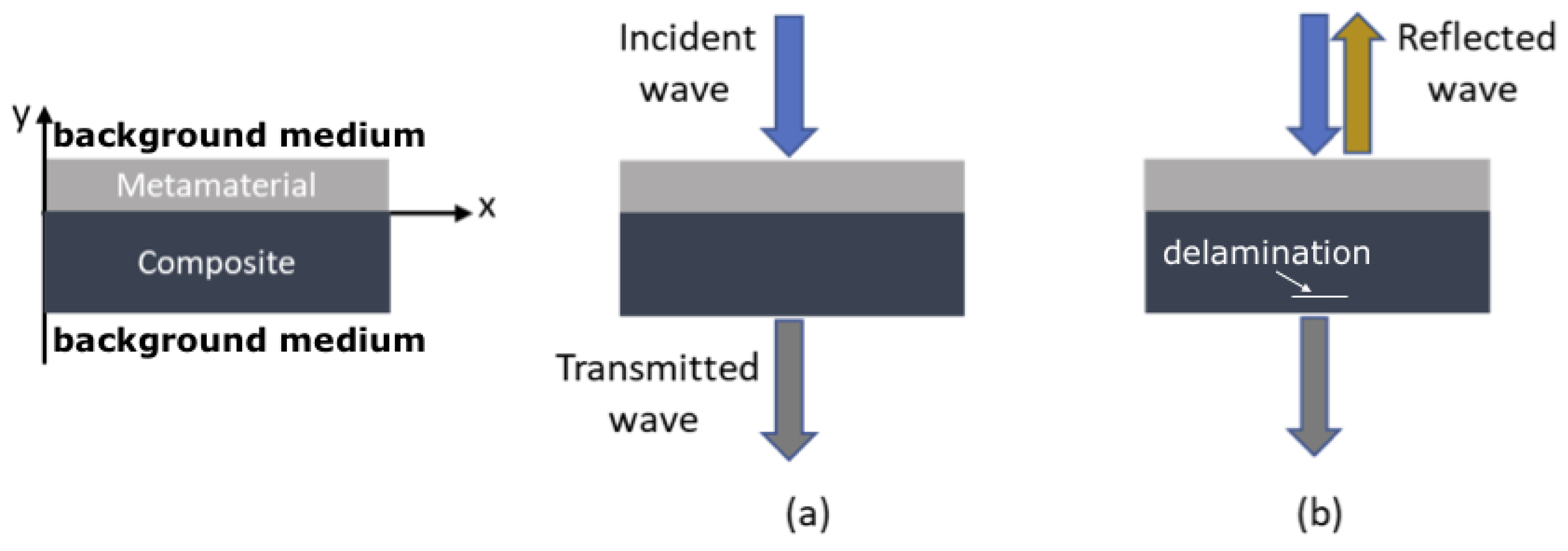
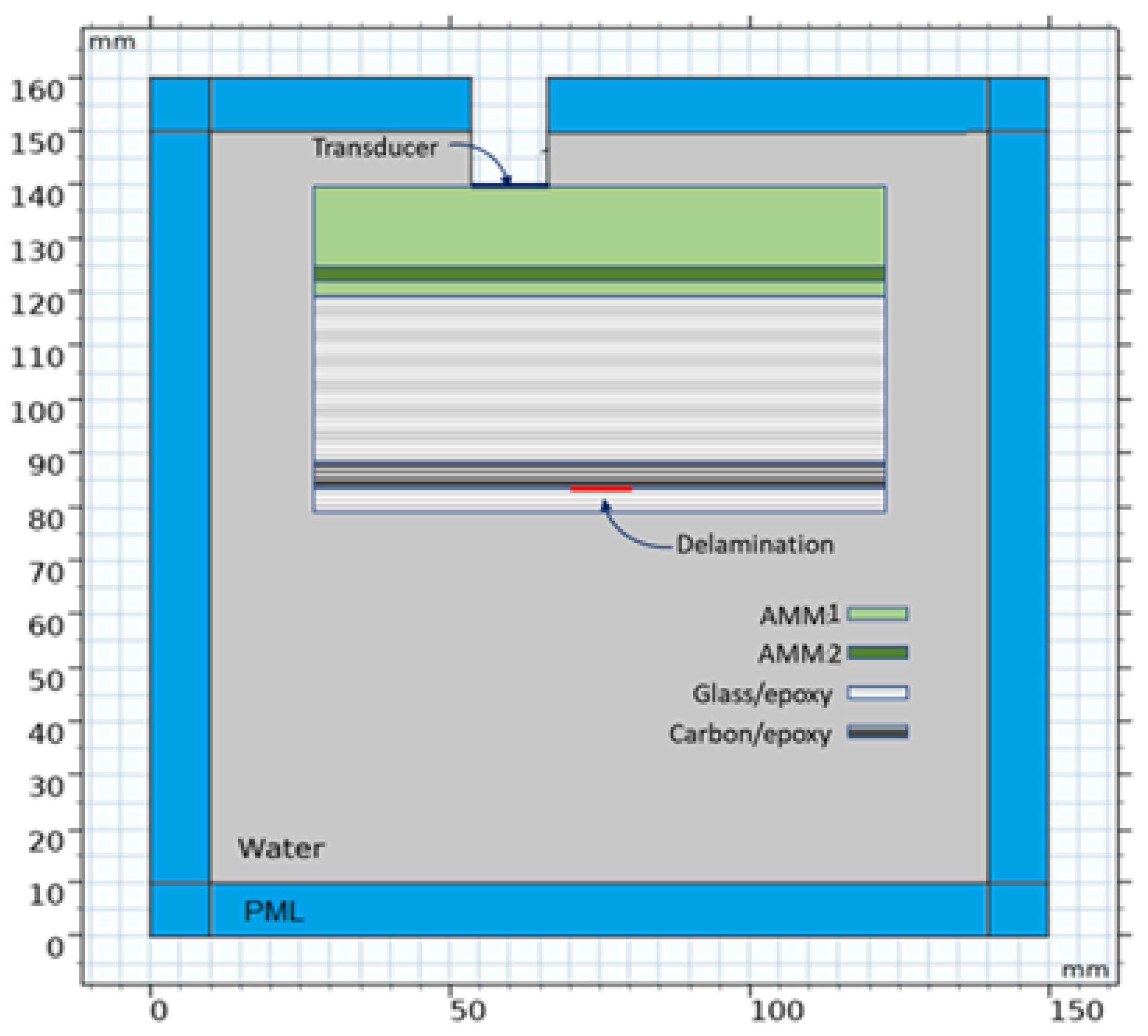
2. Problem Statement

Although the NDE of thin composite laminates using PEUT techniques is well developed, only the complexity of inspecting thick composites is acknowledged in the literature [1]. Composite components used in ship and marine industries generally possess very thick sections. The propagation of ultrasound waves in composite laminates with a high degree of elastic anisotropy is not straightforward. The existence of density variations, high porosity volume (5–15%), and many interfaces affect the scatter and attenuation of an ultrasound beam in composite laminates. These effects generally become more severe in thick hybrid composite laminates. Since these structures may be exposed to extremely high static and cyclic loads, early detection of flaws and/or defects is vital.
To demonstrate current challenges, the attenuation problem in a unidirectional thick hybrid composite laminate during ultrasonic testing is simulated using Comsol Multiphysics 6.0. The mass density and speed of sound for a 40 mm-thick hybrid laminate with an arbitrary stacking sequence of [G15/C32/G100] are given in Table 1 [18]. The inspection is conducted using the pulse-echo method with a flat transducer (diameter = 12.7 mm) while the composite laminate is immersed in water (Figure 1). A perfectly matched layer (PML) was placed along the boundary of the entire model to avoid the effects of reflections.
The PEUT method was simulated by applying an incident wave with a Gaussian modulated sine shape on the transducer in which the velocity is given as:
V n ( t ) = exp ( ( t t 0 ) 2 2 σ 2 ) sin ( 2 π f 0 t )
where the delay time t 0 = 2 / f 0 and the standard deviation is given by σ = 2 / 4 f 0 , while f 0 is the signal center frequency (in this study, 1 MHz). In this simulation, the 40 mm-thick composite laminate contains a 0.025 mm-thick delamination with a length of 10 mm. Two locations of the delamination were considered: shallow and deep delamination corresponding to 20 mm and 5 mm from the back face of the composite laminate, respectively. The signal emitted by the transducer travels through the water domain, impinges the composite laminate and delamination (containing air), and is reflected. Acoustic pressure profiles in the water and the composite laminate at different time steps for two delamination cases are given in Figure 2. It can be seen that due to acoustic attenuation, the effect of the deep delamination is not significant on the pressure profile. As shown in Figure 2b, the amplitude of the reflected signal due to the deep delamination is much smaller than that due to the shallow delamination. Such a weak signal cannot represent the flaw in the composite laminate, considering its non-homogeneity and the significant volume of voids.
Acoustic pressure profiles averaged over the transducer surface are shown in Figure 3. When there is no delamination (Figure 3a), the reflected signal from the front and back faces of the composite can be clearly identified. After introducing the shallow delamination, the amplitude of the reflected signal due to the defect is about 75% of the incident pressure (Figure 3b). However, for the deep delamination (Figure 3c), the reflected pressure is not distinguishable from the back face signal. Only the travel time, which depends on the distance from the transducer and the speed of sound in different media, was slightly impacted. Such a small change in the travel time, around 3 μs, makes delamination detection challenging, considering possible porosity and other manufacturing-related defects and flaws in the laminate.

3. Acoustic Metamaterials: Design Specifications

By tailoring the effective acoustic properties, AMMs could be designed to cloak the virgin composite laminate, allowing the acoustic waves to pass through the laminate without significant reflection. The acoustic cloaking is achieved by “cancelling out” the composite laminate for the propagating waves using metamaterials with double-negative acoustic properties. Since the design of an AMM is based on the acoustic properties of the virgin composite laminate, any delamination (a small volume filled with air) would be acoustically visible. As illustrated in Figure 4, due to the negative effective mass density and negative bulk modulus of the AMM, there will be almost no reflection at the transducer when the incident wave impinges on the composite laminate. However, the incident wave will be scattered after introducing delamination since the AMMs will not cancel out the internal defects. Using the proposed AMMs, the location and size of any delamination would be determined regardless of the thickness of the composite laminate.
Transformation acoustics (TA) is a tool for designing an AMM based on the invariance of the acoustic wave equation under coordinate transformations [24,25]. A metamaterial system with effective acoustic properties for canceling the effect of the composite laminate can be designed using the TA method. In this way, a sound wave incident from a specified direction will pass through and around the thick hybrid composite laminate as though the laminate is not present. For cloaking the composite laminate, the following conditions must be established between the effective mass density, ρ, and compressibility, β, tensors of the metamaterials and the virgin composite laminate (no delamination in present).
[ ρ a ]   1 = A [ ρ c ] 1 A T / d e t A
β a = β c / d e t A
where ρ a ( x a , y a , z a ) , β a ( x a , y a , z a ) and ρ c ( x c , y c , z c ) , β c ( x c , y c , z c ) are the effective mass density and effective compressibility tensors of the AMMs and the composite laminate, respectively. Note that the effective bulk modulus of the AMM can be calculated as B = 1 / β . In Equations (2) and (3), A is the Jacobian transformation tensor and is given as:
A = [ 𝜕 x ( a ) 𝜕 x ( c ) 𝜕 x ( a ) 𝜕 y ( c ) 𝜕 y ( a ) 𝜕 x ( c ) 𝜕 y ( a ) 𝜕 y ( c ) 𝜕 x ( a ) 𝜕 z ( c ) 𝜕 y ( a ) 𝜕 z ( c ) 𝜕 z ( a ) 𝜕 x ( c ) 𝜕 z ( a ) 𝜕 y ( c ) 𝜕 z ( a ) 𝜕 z ( c ) ] .
In this study, a 2D model made to examine the capabilities of AMMs in enhancing the NDE of a thick hybrid composite laminate is examined. Therefore, the wave propagation occurs in the x-y plane only, and the z-components in the Jacobian matrix are zero. Furthermore, in evaluating the Jacobian tensor, the following assumptions are made:
  • The lengths of the metamaterials and the composite laminate (in the x-direction, as shown in Figure 4) are equal. Therefore, 𝜕 x a 𝜕 x c = 1 ;
  • The thickness of each of the metamaterials is set arbitrarily to be half that of the composite laminate, which results in 𝜕 y a 𝜕 y c = 0.5 , where the negative sign is to cancel out the acoustic information of the composite laminate. It should be noted that the thickness of the metamaterials does not depend on the thickness of the composite laminate;
  • The transformations in the x- and y-directions are independent, then 𝜕 x a 𝜕 y c = 𝜕 y a 𝜕 x c = 0 .
Note that the magnitude of the off-diagonal components in the Jacobian tensor depends on the geometry under consideration. However, the non-zero components can be eliminated for any geometry using the coordinate rotations method [26].
Based on the assumptions mentioned above, the Jacobian transformation tensor reduces to:
A = [ 1 0 0 1 / 2 ] .
Accordingly, the effective mass density and the effective bulk modulus (where B = 1 / β ) tensors of an AMM can be obtained as
ρ a = [ 1 / 2 0 0 2 ] × ρ c
B a = 1 / 2 × B c .
AMMs that exhibit the required acoustic properties in Equations (6) and (7) can be designed. Many methods for developing acoustic cloaks are given in the literature [27,28,29,30,31,32,33,34]. For example, it was shown that acoustic cloaks could be fabricated using concentric multilayered structures with homogeneous isotropic materials [35,36]. Since the purpose of the present study was to explore the feasibility of using AMMs to enhance the NDE of thick hybrid composite laminates, the detailed designs AMMs are not presented here.

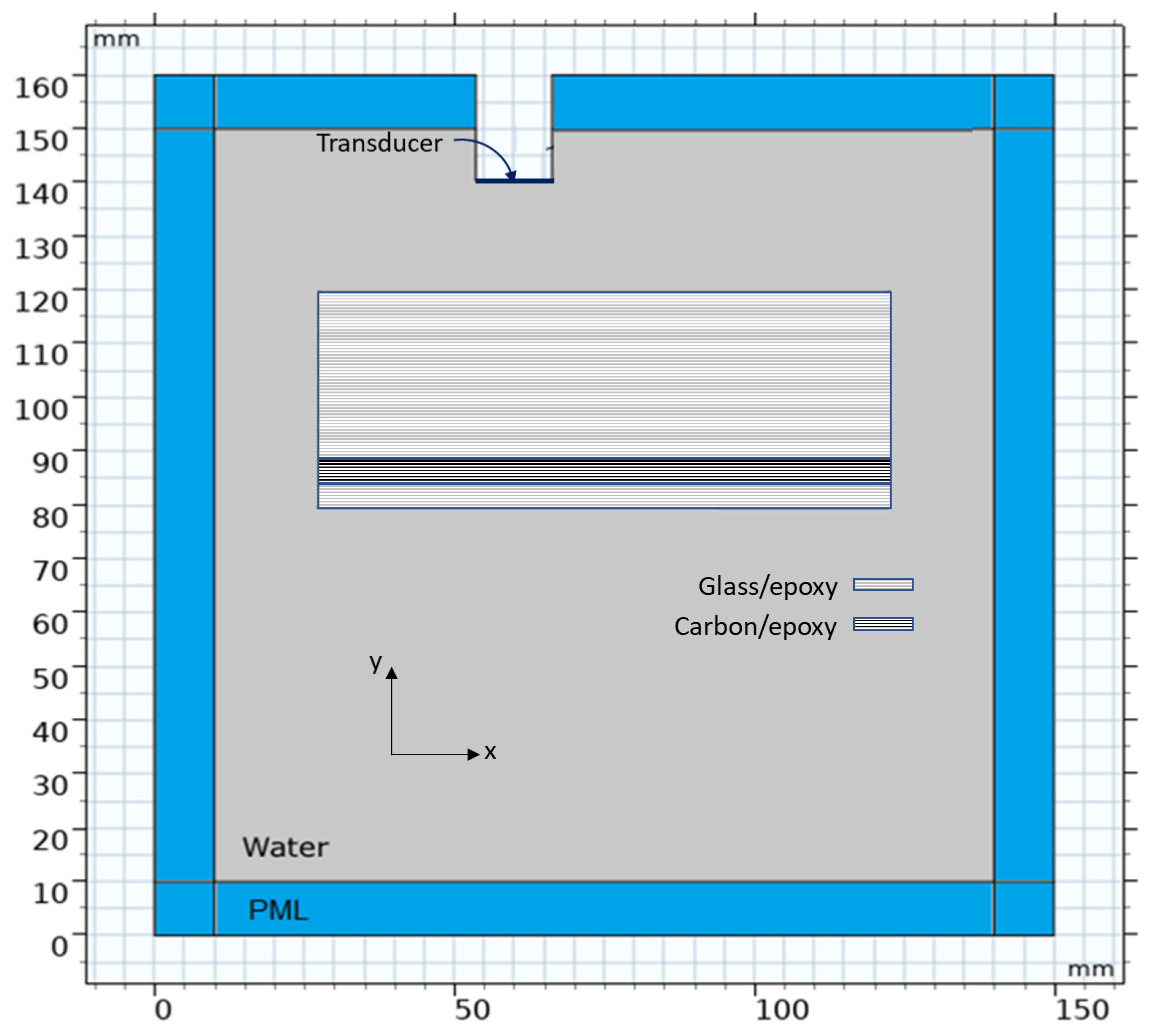
4. Pulse-Echo Ultrasonic Testing Simulation

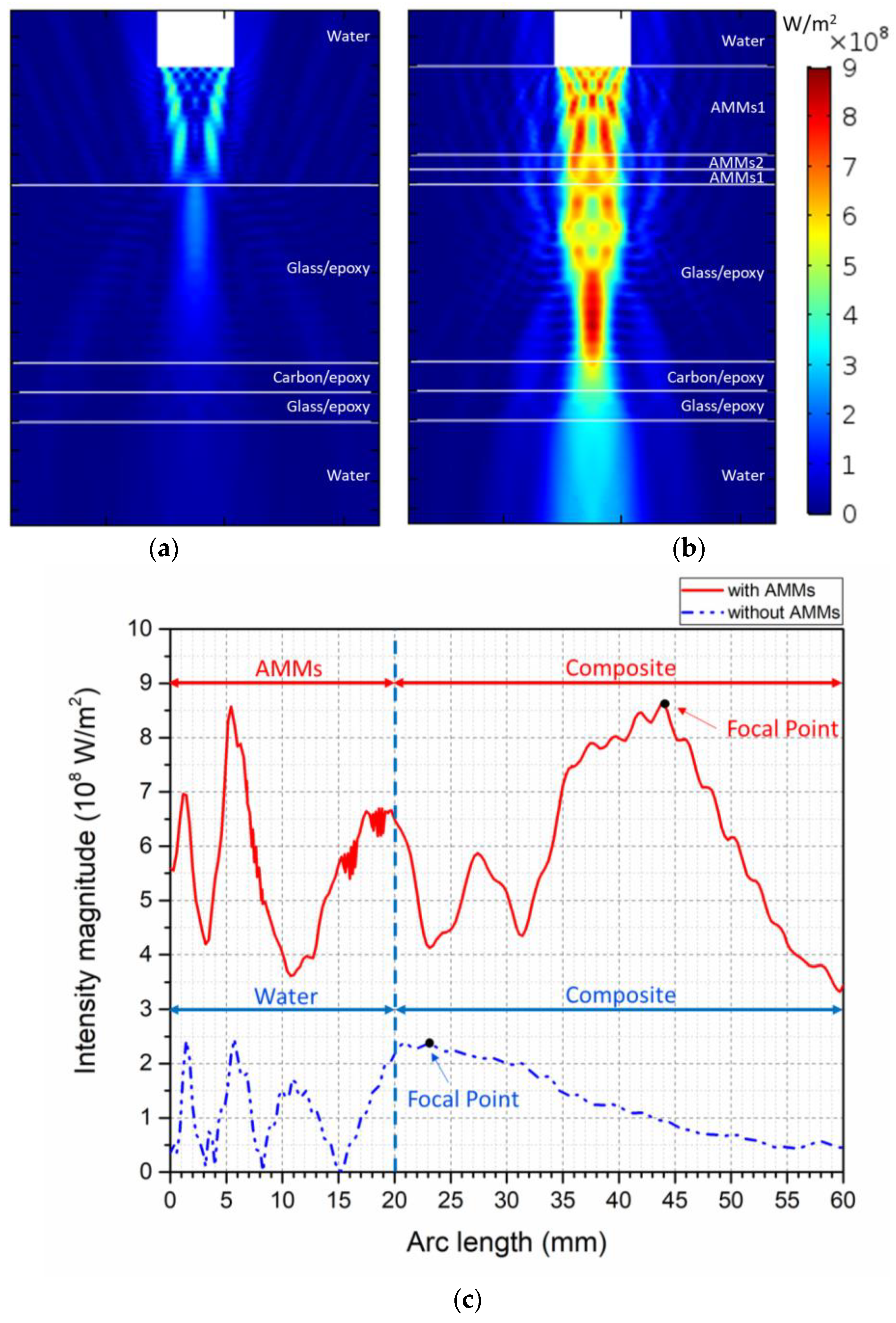
4.1. Effective Acoustic Properties of Metamaterials

A thick hybrid composite laminate with a total thickness of 40 mm, as discussed in Section 2, was considered for the PEUT. Based on the properties of glass fiber/epoxy and carbon fiber/epoxy layers (Table 1), the effective acoustic properties of the AMMs were determined using Equations (6) and (7) to cancel out the effect of the virgin composite laminate. The calculated acoustic properties of the AMM corresponding to the glass fiber/epoxy composite (AMM1) and carbon fiber/epoxy composite (AMM2) laminates are presented in Table 2 (see Figure 5 for illustration). Note that the speed of sound in a metamaterial is calculated using c = B / ρ .

4.2. Frequency Domain to Time Domain Conversion

While frequency domain analysis evaluates the delamination size, a time domain examination is required to determine its location. To this end, the frequency domain simulation was followed by frequency domain to time domain conversion using an inverse fast fourier transform (IFFT) solver in the ComSol Multiphysics platform [37]. The IFFT is computed for input data ω(f0), …, ω(fN−1), collected from the frequency domain analysis, using the following expression:
u ( t k ) = ϕ k j = 0 N 1 ω ( f j ) e 2 π i j k N
for k = 0, …, N − 1. The correction factor ϕ k is defined as:
ϕ k = ϕ k ( f 0 ) = e 2 π i k f 0 F
where F = f N f 0 , which can be interpreted as a shift in the input values for f 0 0 . No negative frequency for real input is chosen so there is no loss of information. The number of input samples N is defined by N = 2 M + 1 , where M = f l o o r ( ( t e n d t s t a r t ) f m a x ) . Frequency list f k and time list t j are defined in the frequency domain study and the frequency-to-time FFT study, respectively [33].

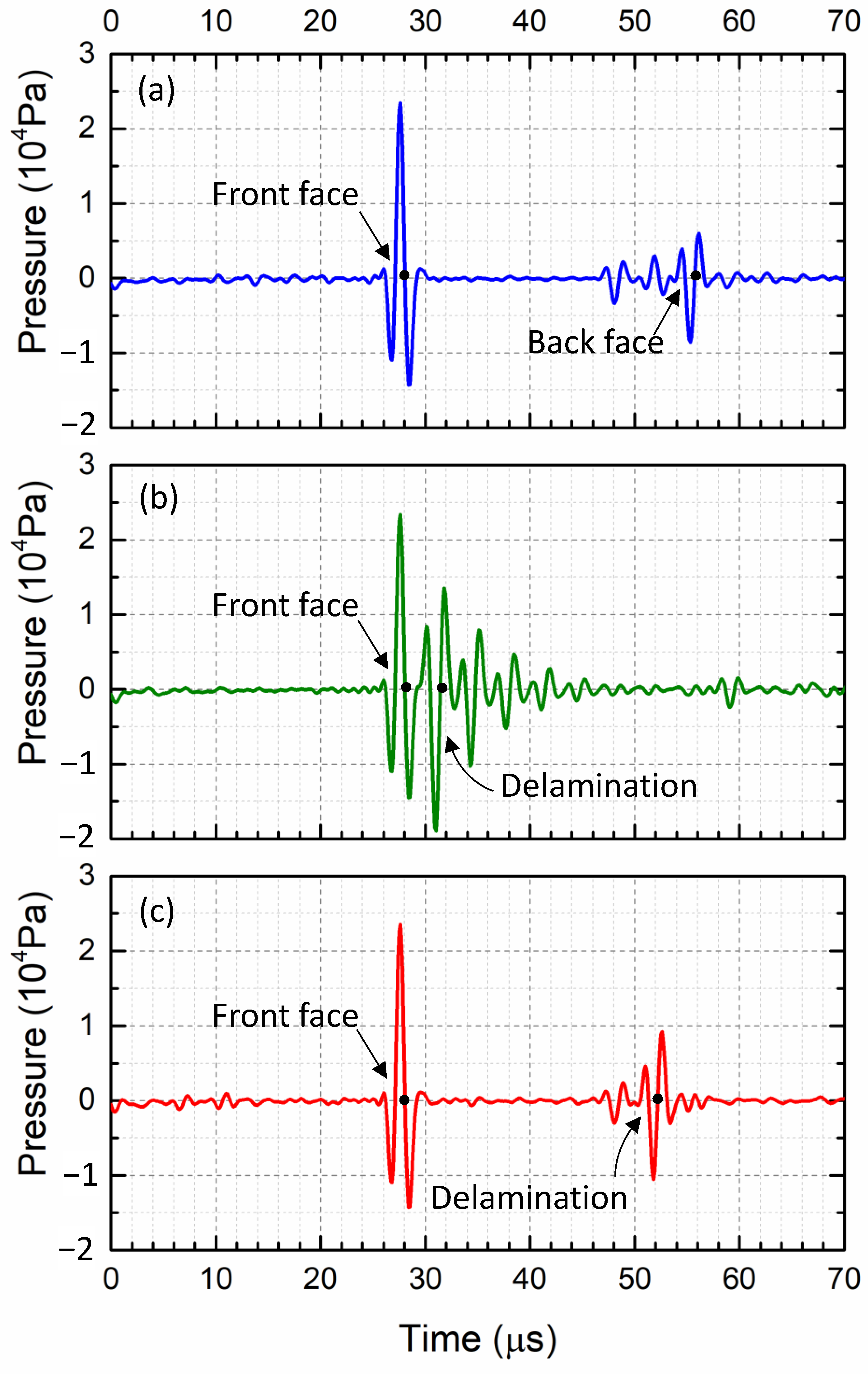
4.3. Signature Scan: Composite Laminate without Delamination

The virgin hybrid composite laminate was analyzed at the frequency domain with- and without the designed AMMs to determine the effect of acoustic metamaterials on the signal intensity. The arbitrary frequency of the incident sound wave, initiated at the transducer, was 0.7 MHz. The proposed AMMs were incorporated on the top surface of the composite laminate. The transducer was moved across the width of the laminate from left to right (x: 55–95 mm) to scan the laminate.
Figure 6a,b illustrates the acoustic intensity profile across the hybrid virgin composite laminate with and without AMMs. As expected, adding the AMMs significantly increased the sound intensity through the composite laminate (see Figure 6b). Figure 6c presents the acoustic intensity magnitude along the dashed center lines, shown in Figure 6a,b. It can be observed that the focal point of sound waves moved by approximately 21 mm in the direction of wave propagation after adding the AMMs, resulting in high energy transmission through the composite laminate. Additionally, by incorporating the AMMs, the maximum intensity was enhanced by almost four times, from 2.3 × 10 8   W / m 2 to 8.6 × 10 8   W / m 2 . Such improvements help to detect deep delaminations and to obtain more precise and accurate images in the presence of flaws.

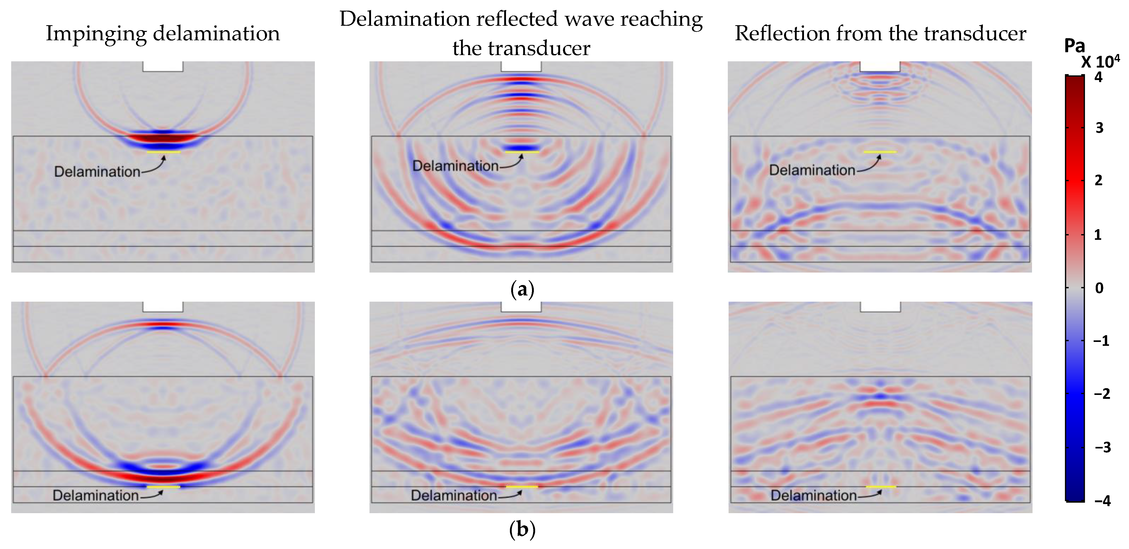
5. Results and Discussion

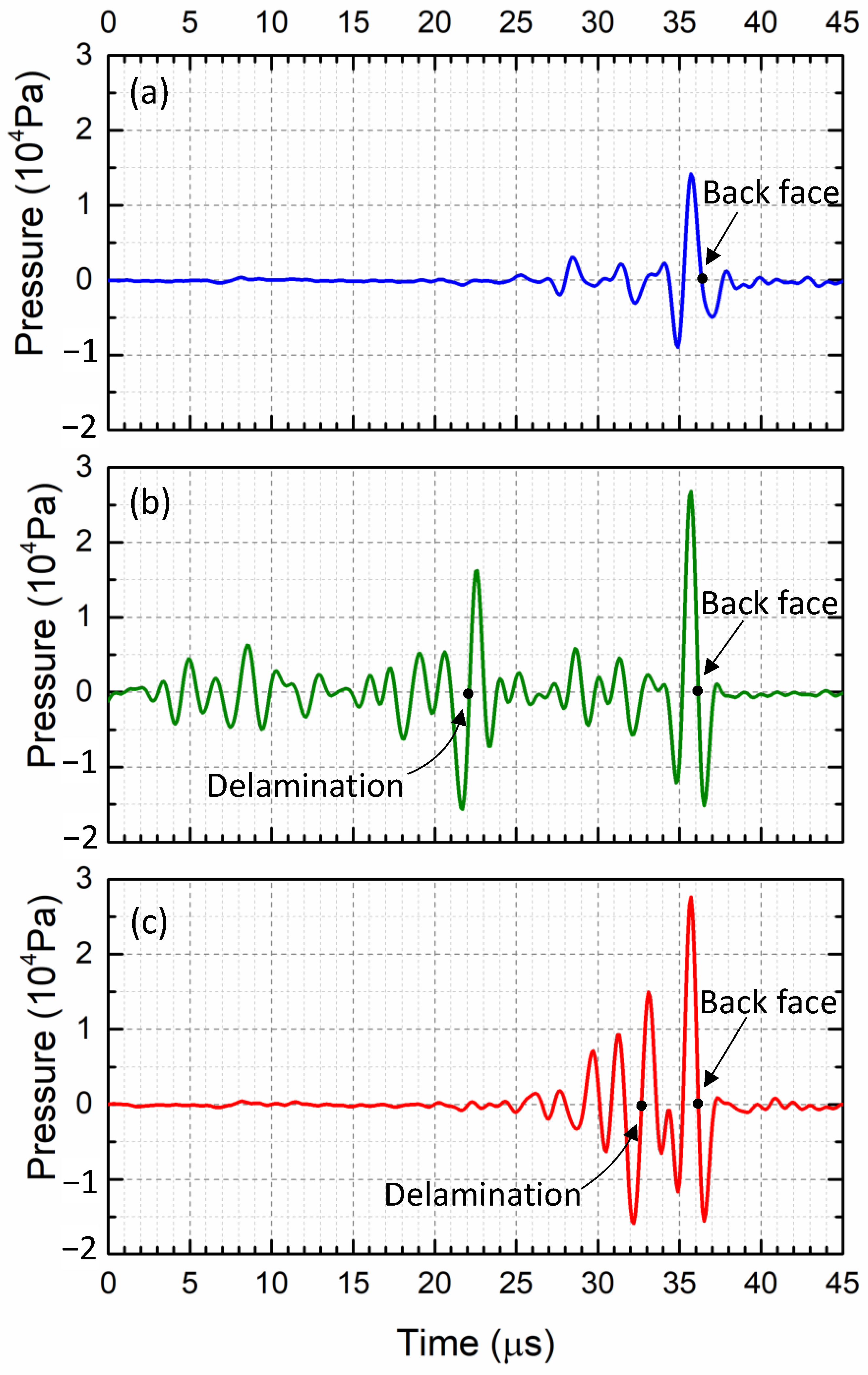
5.1. Location of Delamination

The hybrid composite laminate with a shallow delamination or a deep delamination, respectively, located at 20 mm or 5 mm away from the back face (BF), was inspected numerically. The delamination thickness was 0.025 mm, corresponding to typical peel ply thickness, with a length of 4 mm. The mean acoustic pressure over the transducer surface was recorded (Figure 7). Since the AMMs were added to cloak the virgin composite laminate, only minimal fluctuations could be seen from the reflected signal, while the sound waves were traveling inside the laminate without any defect (Figure 7a). The hybrid composite laminate is acoustically invisible, and only reflected signals from its back face (BF) can be identified. The black dot in Figure 7a indicates a total travel time of 35.2 μs for the incident signal to be reflected from the BF and to reach the transducer.
Figure 7b,c demonstrates an extra peak for the laminate with delamination, regardless of the location of the delamination. Although the thickness of the delamination was 0.025 mm, an out-of-phase reflected signal can be identified due to the existence of the flaw. As shown in these figures, the reflected signal amplitudes due to the shallow and the deep delaminations are 76.9% and 73.1% of the incident pulse, respectively. Due to defects, the magnitude of reflected signals is significant in both cases and can easily be picked up as an abnormality. Furthermore, for the deep delamination (Figure 7c), the reflected signal is 80% higher than that gained from the conventional NDE method, as shown in Figure 3c.
The delamination location can be determined by considering the total travel time for the signal and the associated speed of sound in each medium. The travel times for the shallow and the deep delaminations are 21 μs and 31.7 μs, respectively (Figure 7b,c). Hence, the calculated distance between the internal flaw and the BF of the composite laminate is 20.13 mm (shallow delamination) and 5.10 mm (deep delamination). Comparing the evaluated locations of the delaminations with their actual positions, errors of 0.65% and 2% are obtained for the two cases. Based on the presented results, adding AMMs to conventional PEUT is shown as a promising solution to overcome the challenge of significant attenuation in thick hybrid composite laminates.

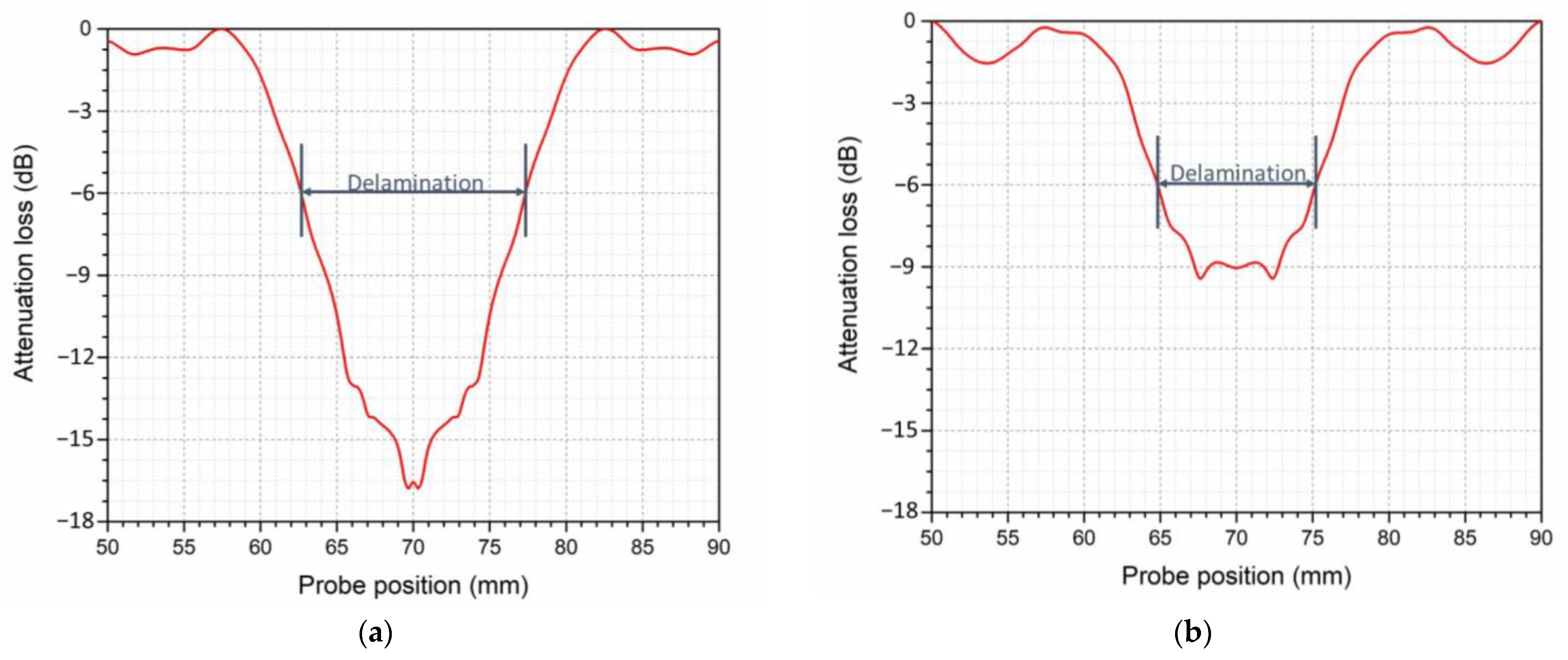
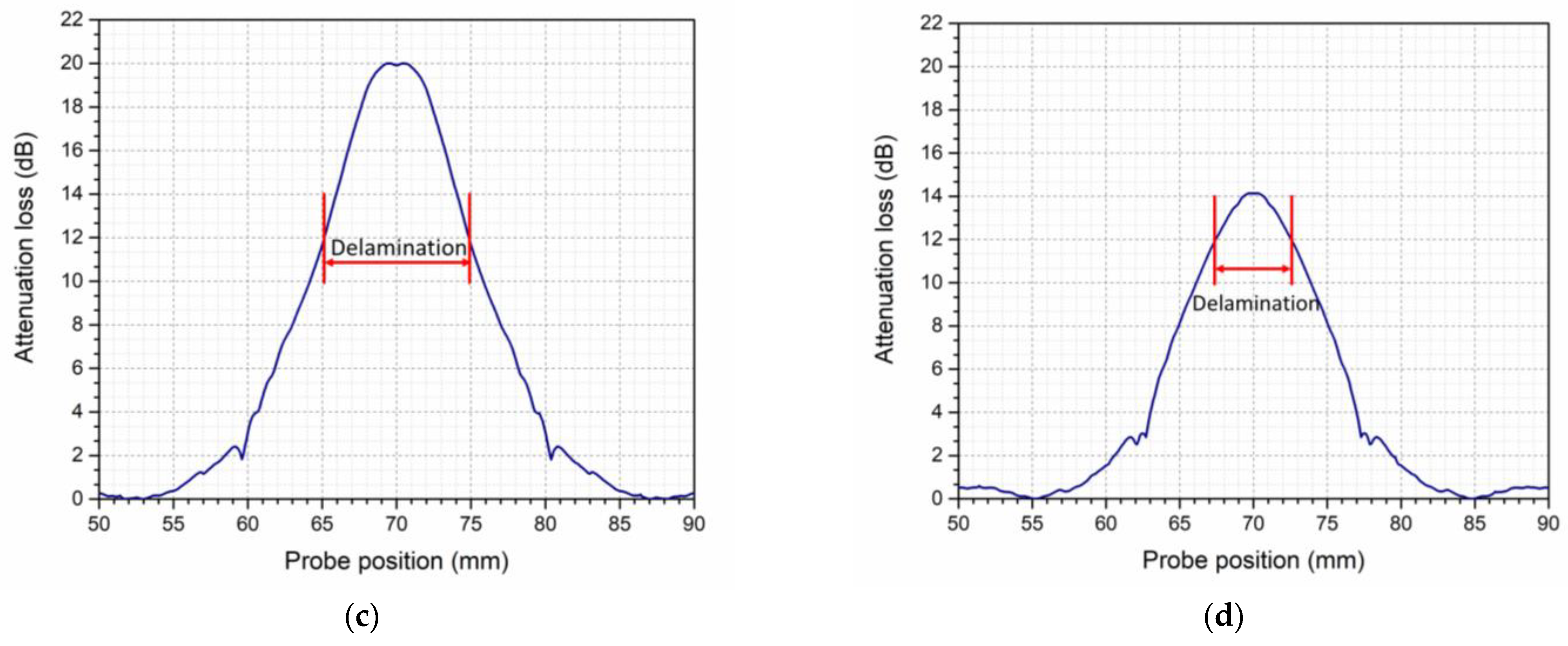
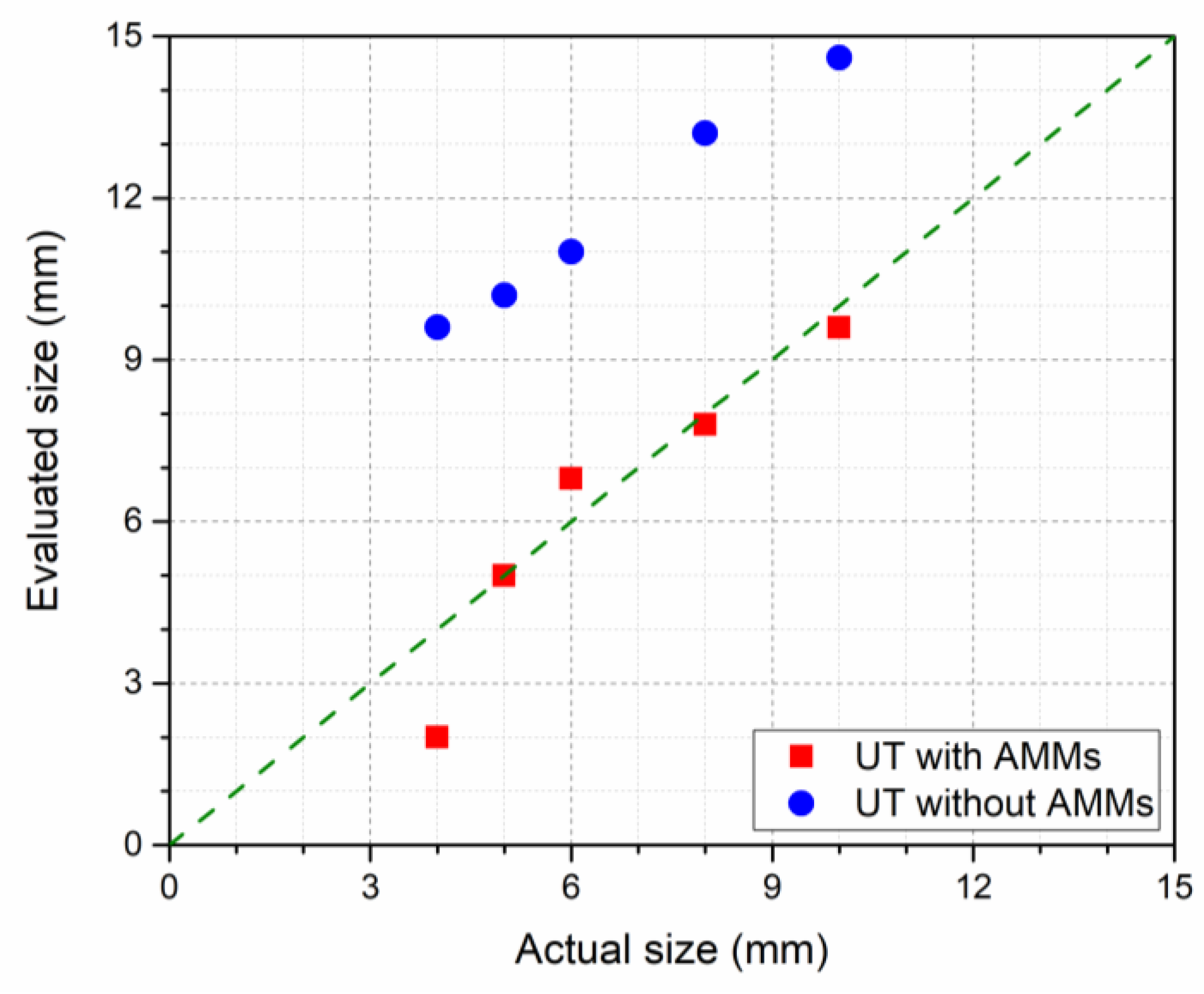
5.2. Size of the Delamination

Locating the defect edge is a common practice for sizing any abnormality in the inspection of composite laminates. Based on the half-power method [18], it is assumed that the edge of the defect can be located when the signal drops by 50% or approximately 6 dB. The accuracy of the proposed NDE solution is examined for PEUT of the composite laminate with deep delaminations of different sizes. Figure 8a,b illustrates attenuation loss when a conventional PEUT method was used to detect deep delaminations of 10 mm and 5 mm. Applying the half-power method, the delamination size was estimated to be 14.6 mm and 10.2 mm, which indicates a 46% and 104% error compared to the actual delamination size.
In the new PEUT method using AMMs, the behavior of reflected signals from any internal defect would be different due to the unique acoustic properties of the designed metamaterials. Therefore, the half-power method may not be used as a threshold for defect detection, and a new criterion is needed. The change in sound attenuation of a thick hybrid composite laminate containing a deep delamination length of 10 mm using the AMM-incorporated PEUT is presented in Figure 8c. The edges of the 10 mm-long defect start at 70 mm and end at 80 mm across the width of the laminate. Referring to Figure 8c, the attenuation change at these two locations is about +12 dB. Therefore, when the new PEUT method is used, a 12 dB increase should be used as the threshold when determining the delamination size. Note that because the entire composite laminate was acoustically cloaked, only the delamination, which was filled with air, caused reflections. Having calibrated the defect edge detection method, the accuracy of the new PEUT method was examined for delamination lengths of 8, 5, and 4 mm.
The attenuation change in a hybrid laminate with delamination of 5 mm is presented in Figure 8d. Using the +12 dB criterion, the exact size of the defect is detected. For other delamination sizes examined in this study, the error arising with detection using a conventional PEUT method was large (Table 3). Using the PEUT method that involves the incorporation of AMMs, the error in determining the delamination size was zero, except when the delamination length was 4 mm when the error was 50%. It should be noted that the selected frequency for inspection plays a significant role in determining the size of the delamination. For detecting small defect sizes, a higher frequency could be used. As can be seen from Table 3, for the same inspection frequency, the accuracy of the detected delamination size is much higher with the new PEUT method with AMMS compared to that provided by the conventional technique.
The accuracy of defect sizing, evaluated using the conventional and the new PEUT methods, is compared in Figure 9. The delamination sizes detected using the new PEUT method show an excellent match with the actual sizes. In contrast, the use of a conventional PEUT method yields large errors. The present results demonstrate that the new pulse-echo ultrasonic testing method that involves the incorporation of AMMs improves delamination detection in thick hybrid composite laminates and enhances the determination of the location and size of these defects in such structures.

6. Conclusions

This study highlighted the challenges in pulse-echo ultrasonic testing (PEUT) of thick hybrid composite laminates and developed a solution by presenting a new method that involves incorporating acoustic metamaterials (AMMs) into the PEUT setup. Using transformation acoustics, metamaterials were designed to cloak the virgin composite laminate. The capability of the new PEUT method was evaluated using numerical analysis in the time domain and frequency domain to detect size and locate deep delaminations in the composite laminate. Delaminations with a thickness of 0.025 mm and lengths as small as 5 mm were detected accurately in a laminate whose total thickness was 40 mm. The results demonstrate the feasibility of the new method of inspection. The results of the numerical simulations confirm the capability of AMMs to improve pulse-echo ultrasonic testing of thick hybrid composite laminates. Thus, this study paves the way for further research on designing and fabricating AMMs to enhance the non-destructive testing of thick hybrid composite laminates.
While introducing a new method to improve the ultrasound testing of thick hybrid composite laminates, this research paper has certain limitations that pave the way for future work in the field. Firstly, the study focused on analyzing single delamination, whereas in practical scenarios, multiple delaminations may exist. Therefore, a fruitful direction for further research would be to investigate the interaction between delaminations and their combined effects on the accuracy of the new PEUT method. Secondly, the paper assumed composite laminates to be homogeneous, neglecting their orthotropic nature. Future studies could incorporate the orthotropic acoustic properties of composite laminates to capture their anisotropic behavior accurately. Considering the complex nature of composite materials, accounting for orthotropy would enhance the accuracy of predictions and enable more realistic modeling of delamination detection and characterization. Addressing these limitations will contribute to understanding and applying non-destructive testing techniques for delamination analysis in thick hybrid composite laminates.

Author Contributions

Conceptualization, A.A.K. and J.Z.; methodology, A.A.K.; software, J.Z.; validation, J.Z.; formal analysis, J.Z.; investigation, J.Z.; resources, A.A.K.; data curation, J.Z.; writing—original draft preparation, J.Z.; writing—review and editing, A.A.K. and R.D.; visualization, J.Z.; supervision, A.A.K. and R.D.; project administration, A.A.K. All authors have read and agreed to the published version of the manuscript.

Funding

This research received no external funding.

Data Availability Statement

Contact the corresponding author.

Conflicts of Interest

The authors declare no conflict of interest.

References

  1. Ibrahim, M. Non-destructive evaluation of thick-section composites and sandwich structures: A review. Compos. Part A Appl. Sci. Manuf. 2014, 64, 36–48. [Google Scholar] [CrossRef]
  2. Senthil, K.; Arockiarajan, A.; Palaninathan, R.; Santhosh, B.; Usha, K. Defects in composite structures: Its effects and prediction methods—A comprehensive review. Compos. Struct. 2013, 106, 139–149. [Google Scholar] [CrossRef]
  3. Gholizadeh, S. A review of non-destructive testing methods of composite materials. Procedia Struct. Integr. 2016, 1, 50–57. [Google Scholar] [CrossRef] [Green Version]
  4. Gandhi, N.; Rose, R.; Croxford, A.J.; Ward, C. Understanding System Complexity in the Non-Destructive Testing of Advanced Composite Products. J. Manuf. Mater. Process. 2022, 6, 71. [Google Scholar] [CrossRef]
  5. Hassani, S.; Dackermann, U. A Systematic Review of Advanced Sensor Technologies for Non-Destructive Testing and Structural Health Monitoring. Sensors 2023, 23, 2204. [Google Scholar] [CrossRef] [PubMed]
  6. Gupta, R.; Mitchell, D.; Blanche, J.; Harper, S.; Tang, W.; Pancholi, K.; Baines, L.; Bucknall, D.G.; Flynn, D. A Review of Sensing Technologies for Non-Destructive Evaluation of Structural Composite Materials. J. Compos. Sci. 2021, 5, 319. [Google Scholar] [CrossRef]
  7. Wronkowicz-Katunin, A.; Katunin, A.; Dragan, K. Reconstruction of Barely Visible Impact Damage in Composite Structures Based on Non-Destructive Evaluation Results. Sensors 2019, 19, 4629. [Google Scholar] [CrossRef] [Green Version]
  8. Gandhi, N.; Rose, R.; Croxford, A.; Ward, C. Developing a high-fidelity knowledge base for improvements in the non-destructive testing of advanced composite material products. Procedia Manuf. 2020, 51, 345–352. [Google Scholar] [CrossRef]
  9. Wang, B.; Zhong, S.; Lee, T.-L.; Fancey, K.S.; Mi, J. Non-destructive testing and evaluation of composite materials/structures: A state-of-the-art review. Adv. Mech. Eng. 2020, 12, 1–28. [Google Scholar] [CrossRef] [Green Version]
  10. Karbhari, V.M. Non-Destructive Evaluation (NDE) of Polymer Matrix Composites; Elsevier: Amsterdam, The Netherlands, 2013. [Google Scholar] [CrossRef]
  11. Fahr, A.; Roge, B.; Brothers, M.; Zimcik, D. Inspection of Thick Composites for Near Surface Flaws. Sci. Eng. Compos. Mater. 2004, 11, 177–184. [Google Scholar] [CrossRef]
  12. Vizentin, G.; Vukelić, G.; Božić, Ž.; Ivošević, Š. Environmentally induced changes in fatigue life and durability of marine structures and vessels. Procedia Struct. Integr. 2022, 42, 793–798. [Google Scholar] [CrossRef]
  13. Gupta, M.K.; Srivastava, R.K. Mechanical Properties of Hybrid Fibers-Reinforced Polymer Composite: A Review. Polym.-Plast. Technol. Eng. 2016, 55, 626–642. [Google Scholar] [CrossRef]
  14. Pérez-Martín, M.J.; Enfedaque, A.; Dickson, W.; Gálvez, F. Impact Behavior of Hybrid Glass/Carbon Epoxy Composites. J. Appl. Mech. 2013, 80, 031803. [Google Scholar] [CrossRef]
  15. Sevkat, E.; Liaw, B.; Delale, F.; Raju, B.B. Effect of repeated impacts on the response of plain-woven hybrid composites. Compos. Part B Eng. 2010, 41, 403–413. [Google Scholar] [CrossRef]
  16. Imielińska, K.; Castaings, M.; Wojtyra, R.; Haras, J.; Le Clezio, E.; Hosten, B. Air-coupled ultrasonic C-scan technique in impact response testing of carbon fibre and hybrid: Glass, carbon and Kevlar/epoxy composites. J. Mater. Process. Technol. 2004, 157–158, 513–522. [Google Scholar] [CrossRef]
  17. Grabovac, I.; Whittaker, D. Application of bonded composites in the repair of ships structures—A 15-year service experience. Compos. Part A Appl. Sci. Manuf. 2009, 40, 1381–1398. [Google Scholar] [CrossRef]
  18. Ibrahim, M.E. Ultrasonic inspection of hybrid polymer matrix composites. Compos. Sci. Technol. 2021, 208, 108755. [Google Scholar] [CrossRef]
  19. Mouritz, A.; Townsend, C.; Khan, M.S. Non-destructive detection of fatigue damage in thick composites by pulse-echo ultrasonics. Compos. Sci. Technol. 2000, 60, 23–32. [Google Scholar] [CrossRef]
  20. Mal, A.; Yin, C.-C.; Bar-Cohen, Y. Ultrasonic non-destructive evaluation of cracked composite laminates. Compos. Eng. 1991, 1, 85–101. [Google Scholar] [CrossRef] [Green Version]
  21. Holmes, C.; Drinkwater, B.W.; Wilcox, P.D. Post-processing of the full matrix of ultrasonic transmit–receive array data for non-destructive evaluation. NDT E Int. 2005, 38, 701–711. [Google Scholar] [CrossRef]
  22. Hsu, D.K.; Barnard, D.J. Inspecting composites with airborne ultrasound: Through thick and thin. In AIP Conference Proceedings; American Institute of Physics: College Park, MD, USA, 2006. [Google Scholar] [CrossRef]
  23. Costigan, G.; Whalley, P.B. Measurements of the speed of sound in air-water flows. Chem. Eng. J. 1997, 66, 131–135. [Google Scholar] [CrossRef]
  24. Cummer, S.A.; Schurig, D. One path to acoustic cloaking. New J. Phys. 2007, 9, 45. [Google Scholar] [CrossRef]
  25. Chen, H.; Chan, C.T. Acoustic cloaking in three dimensions using acoustic metamaterials. Appl. Phys. Lett. 2007, 91, 183518. [Google Scholar] [CrossRef]
  26. Chen, H.; Chan, C.T. Acoustic cloaking and transformation acoustics. J. Phys. D Appl. Phys. 2010, 43, 113001. [Google Scholar] [CrossRef]
  27. Aubry, A.; Lei, D.Y.; Maier, S.A.; Pendry, J.B. Interaction between Plasmonic Nanoparticles Revisited with Transformation Optics. Phys. Rev. Lett. 2010, 105, 233901. [Google Scholar] [CrossRef]
  28. Cummer, S.A.; Christensen, J.; Alù, A. Controlling sound with acoustic metamaterials. Nat. Rev. Mater. 2016, 1, 16001. [Google Scholar] [CrossRef] [Green Version]
  29. Haberman, M.R.; Guild, M.D. Acoustic metamaterials. Phys. Today 2016, 69, 42–48. [Google Scholar] [CrossRef] [Green Version]
  30. Guild, M.D.; Haberman, M.R.; Aluù, A. Cancellation of the acoustic field scattered from an elastic sphere using periodic isotropic elastic layers. J. Acoust. Soc. Am. 2010, 128, 2374. [Google Scholar] [CrossRef]
  31. Guild, M.D.; Alù, A.; Haberman, M.R. Cancellation of acoustic scattering from an elastic sphere. J. Acoust. Soc. Am. 2011, 129, 1355–1365. [Google Scholar] [CrossRef]
  32. García-Chocano, V.M.; Sanchis, L.; Díaz-Rubio, A.; Martínez-Pastor, J.; Cervera, F.; Llopis-Pontiveros, R.; Sánchez-Dehesa, J. Acoustic cloak for airborne sound by inverse design. Appl. Phys. Lett. 2011, 99, 074102. [Google Scholar] [CrossRef]
  33. Sanchis, L.; García-Chocano, V.M.; Llopis-Pontiveros, R.; Climente, A.; Martínez-Pastor, J.; Cervera, F.; Sánchez-Dehesa, J. Three-Dimensional Axisymmetric Cloak Based on the Cancellation of Acoustic Scattering from a Sphere. Phys. Rev. Lett. 2013, 110, 124301. [Google Scholar] [CrossRef]
  34. Lu, Z.; Wilson, T.W.; Lu, Y.; Ho, C.S.; Zhang, M.W.; Ho, R.C. Acoustic cloak based on Bézier scatterers. Sci. Rep. 2018, 8, 12924. [Google Scholar] [CrossRef] [PubMed] [Green Version]
  35. Cheng, Y.; Liu, X.J. Three dimensional multilayered acoustic cloak with homogeneous isotropic materials. Appl. Phys. A 2008, 94, 25–30. [Google Scholar] [CrossRef]
  36. Yu, Z.; Feng, Y.; Xu, X.; Zhao, J.; Jiang, T. Optimized cylindrical invisibility cloak with minimum layers of non-magnetic isotropic materials. J. Phys. D Appl. Phys. 2011, 44, 185102. [Google Scholar] [CrossRef]
  37. COMSOL. Acoustics Module User’s Guide; COMSOL AB: Stockholm, Sweden, 2007. [Google Scholar]
Figure 1. A schematic drawing of a thick hybrid composite laminate immersed in water for PEUT.
Jcs 07 00257 g001
Figure 2. Pressure profile showing the source and reflected signals from (a) a shallow delamination and (b) a deep delamination at various times.
Jcs 07 00257 g002
Figure 3. Acoustic pressure measured at the transducer for (a) a virgin composite laminate, (b) a composite laminate with a shallow delamination, and (c) a composite laminate with a deep delamination.
Jcs 07 00257 g003
Figure 4. Schematic presentation of the concept of incorporating metamaterials to act as acoustic cloaks, (a) composite laminate without any defect, and (b) composite laminate with delamination.
Jcs 07 00257 g004
Figure 5. A schematic drawing showing AMMs incorporated in the pulse-echo ultrasonic testing of a thick hybrid composite laminate containing a delamination located 5 mm from the back face.
Jcs 07 00257 g005
Figure 6. Intensity profiles in the thick hybrid composite laminate: (a) without AMMs, (b) with AMMs, and (c) intensity magnitudes along the dashed line in (a,b).
Jcs 07 00257 g006
Figure 7. Acoustic pressure measured at the transducer for PEUT of a thick hybrid composite laminate (a) without delamination, (b) with a shallow delamination, and (c) with a deep delamination.
Jcs 07 00257 g007
Figure 8. Attenuation change for inspection of a deep delamination using (a,b) a conventional pulse-echo ultrasonic testing (PEUT) method and (c,d) the new method (PEUT with AMMs). Delamination size for (a,c) = 10 mm and for (b,d) = 5 mm.
Jcs 07 00257 g008aJcs 07 00257 g008b
Figure 9. Comparison of the estimated size of a delamination obtained using a conventional pulse-echo ultrasonic testing method and the proposed method that utilizes acoustic metamaterials (AMMs).
Jcs 07 00257 g009
Table 1. Properties of materials and fluids.
Material/MediumDensity ( kg / m 3 ) Speed of Sound ( m / s )
Glass fiber/epoxy composite [18] 2153   ( ± 5 ) 2917   ( ± 3 )
Carbon fiber/epoxy composite [18] 1581   ( ± 5 ) 2614   ( ± 3 )
Water [23]10001481
Air [23]1.225343
Table 2. Acoustic properties of the designed AMMs.
AMMOrientationDensity ( kg / m 3 ) Speed of Sound ( m / s )
AMM1x 1076.5 2917
y 4306 1458.5
AMM2x 790.5 2614
y 3162 1307
Table 3. Comparison of delamination size detected using conventional and new pulse-echo ultrasonic testing (PEUT) methods (percentage error is given in the parentheses).
Delamination Length (mm) 854
Detected defect length (mm)Conventional PEUT method13.2 (65%)10.2 (104%)9.6 (140%)
PEUT with AMMs8 (0%)5 (0%)2 (50%)
Disclaimer/Publisher’s Note: The statements, opinions and data contained in all publications are solely those of the individual author(s) and contributor(s) and not of MDPI and/or the editor(s). MDPI and/or the editor(s) disclaim responsibility for any injury to people or property resulting from any ideas, methods, instructions or products referred to in the content.

