Article

Numerical Investigation of Flexural Behavior of Reinforced Concrete (RC) T-Beams Strengthened with Pre-Stressed Iron-Based (FeMnSiCrNi) Shape Memory Alloy Bars

1
Materials Science and Engineering Program, College of Arts and Sciences, American University of Sharjah, Sharjah P.O. Box 26666, United Arab Emirates
2
Department of Civil Engineering, American University of Sharjah, Sharjah P.O. Box 26666, United Arab Emirates
3
Structural Engineering Department, Faculty of Engineering, Tanta University, Tanta P.O. Box 31733, Egypt
4
Department of Mechanical Engineering, American University of Sharjah, Sharjah P.O. Box 26666, United Arab Emirates
*
Author to whom correspondence should be addressed.
J. Compos. Sci. 2023, 7(6), 258; https://doi.org/10.3390/jcs7060258
Submission received: 3 April 2023 / Revised: 29 May 2023 / Accepted: 15 June 2023 / Published: 19 June 2023
(This article belongs to the Section Composites Modelling and Characterization)

Abstract

:
Shape memory alloy (SMA) is a material that can change shape in response to external stimuli such as temperature, stress, or magnetic fields. SMA types include nitinol (nickel-titanium), copper-aluminum-nickel, copper-zinc-aluminum, iron-manganese-silicon, and various nickel-titanium-X alloys, each exhibiting unique shape memory properties for different applications. Reinforced concrete (RC) T-beams strengthened and pre-stressed with Fe-SMA bars are numerically investigated for their flexural response under the influence of various parameters. The bars are embedded in a concrete layer attached to the beam’s soffit. Based on the numerical results, it was found that increasing the compression strength from 30 to 60 MPa slightly improves the beam’s strength (by 2%), but it significantly increases its ductility by approximately 45%. As opposed to this, the strength and ductility of the pre-stressed T-beam are considerably improved by using a larger diameter of Fe-SMA bars. Specifically, using 12 mm Fe-SMA bar over 6 mm resulted in 65% and 47% greater strength and ductility, respectively. Furthermore, this study examines the importance of considering the flange in the flexural design of pre-stressed beams. It is seen that considering a 500 mm flange width enhanced the ductility by 25% compared to the rectangular-section beam. The authors recommend further experimental work to validate and supplement the calculations and methodology used in the current numerical analysis.

1. Introduction

Reinforced concrete (RC) structures are susceptible to damage caused by aging and deterioration, which can result in cracking, spalling, corrosion, fracture, and buckled rebars. The impact of this damage can have an unfavorable effect on the robustness and operational capacity of RC structures, ultimately causing safety issues to arise. To address these issues, various strengthening and repair materials have been developed, including ultra-high-performance based on: strain-hardening cementitious composites (UHP-SHCC) [1,2,3,4,5], fiber-reinforced geopolymer concrete (UHP-FRGC) [6], and fiber-reinforced concrete (UHPFRC) [7]. Additionally, fiber-reinforced polymer (FRP) sheets and rebars with near-surface attachments (NSM) [8,9,10,11,12,13,14,15,16] and externally bonded reinforcements (EBR) [17,18,19,20,21,22,23,24,25] are well known for strengthening RC structures. However, several studies have shown that high temperatures significantly degrade the mechanical properties of FRP composites [26,27,28]. Due to the limitations of FRP laminates, researchers have been exploring alternative materials for strengthening rebars, including shape memory alloys (SMAs).
Iron is the primary component of iron-based shape memory materials (Fe-SMA), which can be reshaped after deformation, typically through heating or cooling. These alloys mainly comprise iron and other alloying elements such as nickel, manganese, and chromium. Compared to other SMAs, such as those based on copper, nickel, or titanium, iron-based SMAs have several advantages. For example, they show a relatively low cost, good corrosion resistance, high damping capacity, high strength, large strain capacity, and good biocompatibility [29]. Steel-reinforced concrete structural elements can be strengthened and repaired with SMAs. In addition, when heated, SMA bars can trigger the shape memory effect and generate pre-stressing forces on reinforced concrete elements. Additionally, the structural seismic performance of SMAs is superior to that of FRPs [29,30]. Additionally, according to Sidharth et al. [31], FeMnAlNiTi, which are shape memory alloys based on iron, exhibited remarkable functional performance restoration [31]. A key benefit of SMAs is their ease of installation, making them a viable option for strengthening, especially when it comes to minimizing residual deformations and maintaining functionality after extreme loading events [31]. To date, several review papers [32,33,34,35,36,37] have been published on SMAs from the standpoint of materials and modeling/simulations; among them, several papers on strengthening applications have been reported.
Hong et al. [38] carried out a research study to examine the structural properties (initial stiffness, crack load, and ductility) of RC beams reinforced with Fe-SMA strips [38]. Hong et al. [38] concluded that the pre-stressing effect of Fe-SMA strips increased the cracking load and rigidity of the beams. Ruiz-Pinilla et al. [39] presented an FE simulation of RC beams externally confined by Fe-SMA strips, which resist shear stresses. The numerical results by Ruiz-Pinilla [39] were validated with experimental data. Furthermore, Shahverdi et al. [40] conducted an experimental study investigating the strength and pre-stressing of Fe-SMA-reinforced RC beams. Their study focused on the use of Fe-SMA strips for NSMs strengthening. The NSM technique involved creating grooves in the cover and then placing ribbed Fe-SMA strips inside them. According to the experiments conducted, strengthening RC beams with NSM and pre-stressing them with Fe-SMAs worked well.
Pre-stressed T-beams and rectangular beams are both commonly used in construction. However, T-beam offers several advantages over rectangular beams in specific applications, i.e., bridge construction. One of the main advantages is that T-beam provides a more efficient distribution of stresses throughout the beam. Furthermore, the T-beam is more efficient in resisting bending and torsion forces. Undoubtedly, T-section beams are extensively used in civil engineering construction. However, to the best of the authors’ knowledge, very few studies have investigated the structural behavior of RC T-beams strengthened with Fe-SMA [41,42]. Cladera et al. [41] proposed a method to strengthen RC T-beams by externally anchoring U-shaped Fe-SMA strips to the beam’s web. Prestrained strips were thermally activated at 160 °C. Additionally, their experiments showed delayed crack appearance and improved shear capacity when U-shaped Fe-SMA strips were used. Nevertheless, the ductility of the samples was lower than anticipated and this could be attributed to the technique of anchoring the SMA strips to the T-beams. A recent study by Czaderski et al. [42] embedded Fe-SMA in a mortar layer to strengthen large-scale T-beams. A significant improvement in a beam’s shear capacity was achieved through active SMA stirrups in reducing the beam’s deflection, cracking, and stresses. According to Czaderski et al. [42], the ease of application of the proposed strengthening technique made it suitable for onsite applications.
Finite element analysis (FEA) is a numerical method that solves complex engineering problems by dividing the structure into smaller parts called finite elements [43,44]. These elements are then analyzed using computer software to determine the structure’s stresses, strains, and deformations under various loading conditions [45,46]. Concrete structures are commonly analyzed using finite element analysis [47]. An FEA can be used to predict the behavior of reinforced concrete structures subjected to various loads, including dead loads, live loads, wind loads, and earthquake loads [48,49,50,51]. Additionally, experimental findings and numerical results have been found to be in good agreement in several studies (i.e., [52]). It can also be used to investigate the effect of material properties, reinforcement arrangement, and construction methods on the performance of concrete structures [53,54]. Apart from the lack of experimental and numerical studies on RC T-beams reinforced with Fe-SMA, there are also few numerical studies that involve RC beams reinforced with EBR and pre-stressed with Fe-SMA bars (e.g., [55,56,57]). Hence, the main objective of this study is to develop a numerical parametric analysis of RC T-beams strengthened with Fe-SMA by implementing the EBR technique [58]. In this study, a three-dimensional model of an RC T-beam with pretensioned Fe-SMA bars is constructed using the ABAQUS FEM software [58]. The model illustrates the behavior of beams subjected to monotonous loading under static conditions using a four-point bending setup [59]. According to the CDP model, concrete’s nonlinear behavior can be simulated and predicted by concrete parameters such as concrete compression strength (f’c). Parametric models are used in the current study to account for the change in compression strength using different parameters, as recommended by Hafezolghorani et al. [60]. To enable self-equilibrium, a step with no loading is established during the simulation of Fe-SMA bars. Furthermore, Fe-SMA activation in the current study is modeled using the simplified model reported experimentally by Shahverdi et al. [61]. Additionally, Shahverdi et al.’s [61] suggestion is followed for Fe-SMA modelling in ABAQUS, where an adjustment is made in the stress–strain curve of SMA.
This study numerically investigates the effect of different parameters on the flexural performance of RC T-beams pre-stressed with Fe-SMA bars. The FE model was validated in the authors’ previous study [62]. The investigated parameters are (a) concrete compressive strength, (b) Fe-SMA diameter, and (c) flange width of RC T-beams.

2. Description of the FE Numerical Models

In this study, an FEM developed by the authors is used to simulate the behavior of RC T-beams reinforced with Fe-SMA bars. A description of the numerical modeling can be found in this section.

2.1. Material Properties

Three-dimensional finite element models (3-D FEMs) are developed using ABAQUS in order to simulate the behavior of an RC beam under monotonous loading. Each section of the beam, such as the concrete, shotcrete layer, longitudinal and shear steel reinforcements, Fe-SMA bars, and steel plates, are defined in the FE software with their corresponding material attributes and sections. For optimal interaction between the concrete and embedded reinforcement, the rebars are designated as the encased region, with the concrete serving as the host region. Similarly, the shotcrete layer designates Fe-SMA rebars as the embedded areas. Shahverdi et al. [61] showed that the concrete part and the embedded bars had an ideal connection (perfect bond). This hypothesis is used in the numerical model, as mentioned in Khalil et al. [62].

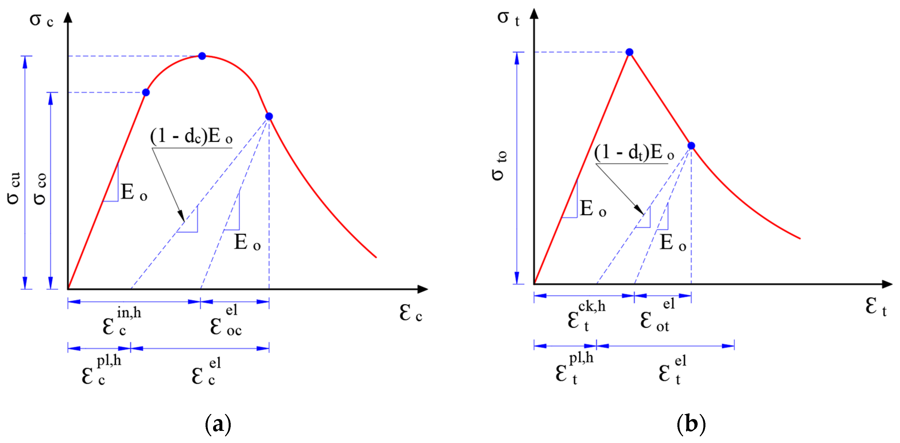
2.1.1. Concrete Definition in ABAQUS

Three different techniques are available in ABAQUS to model the concrete behavior: smeared cracking, brittle cracking, and concrete damage plasticity. However, this study adopts the concrete damage plasticity (CDP) model since this model takes into account cracking under tensile load and crushing under compressive load. In other words, CDP provides an adequate prediction of concrete behavior under bending because it accounts for both tension and compression damages. The concrete response under compression and tensile loadings can be described as shown in Figure 1. Uniaxial constitutive models of concrete in tension and compression begin with a linear segment equal to the concrete modulus ( E o ). A multilinear function is then used to describe the compressive behavior of the concrete when it undergoes plastic deformation and its tendency to weaken under tensile stress. Moreover, the damage in concrete can be determined with respect to the plastic hardening strain, as demonstrated in Table 1.
Table 2 depicts the adopted CDP parameters in this study. In this study, the parameters mentioned in Table 2 are used for all grades of concrete. Those values are specified according to the verification modeling conducted by the authors in their previous study [62]. The dilation angle represents the ratio of the volume-to-shear strain. It is worth noting that the dilation angle should be selected within the range of (15°–56°), as mentioned in [62]. Eccentricity refers to the potential eccentricity at the plastic region, while fb0/fc0 refers to the relationship between initial biaxial strength and initial compressive strength. The K-factor should equal 0.67 based on the loading surface shape. To attain more precise results, a viscosity parameter of 0.0001 is selected while avoiding the divergence throughout the numerical analysis.
Two common approaches are available in ABAQUS [58] for defining the tension-stiffening behavior of concrete. These approaches enable the evaluation of concrete’s behavior after cracking occurs, either through the stress–strain relationship or the crack-opening displacement relationship. The present study simulates concrete’s tension response using crack-opening displacement. Further details can be found in the authors’ previous study [62].

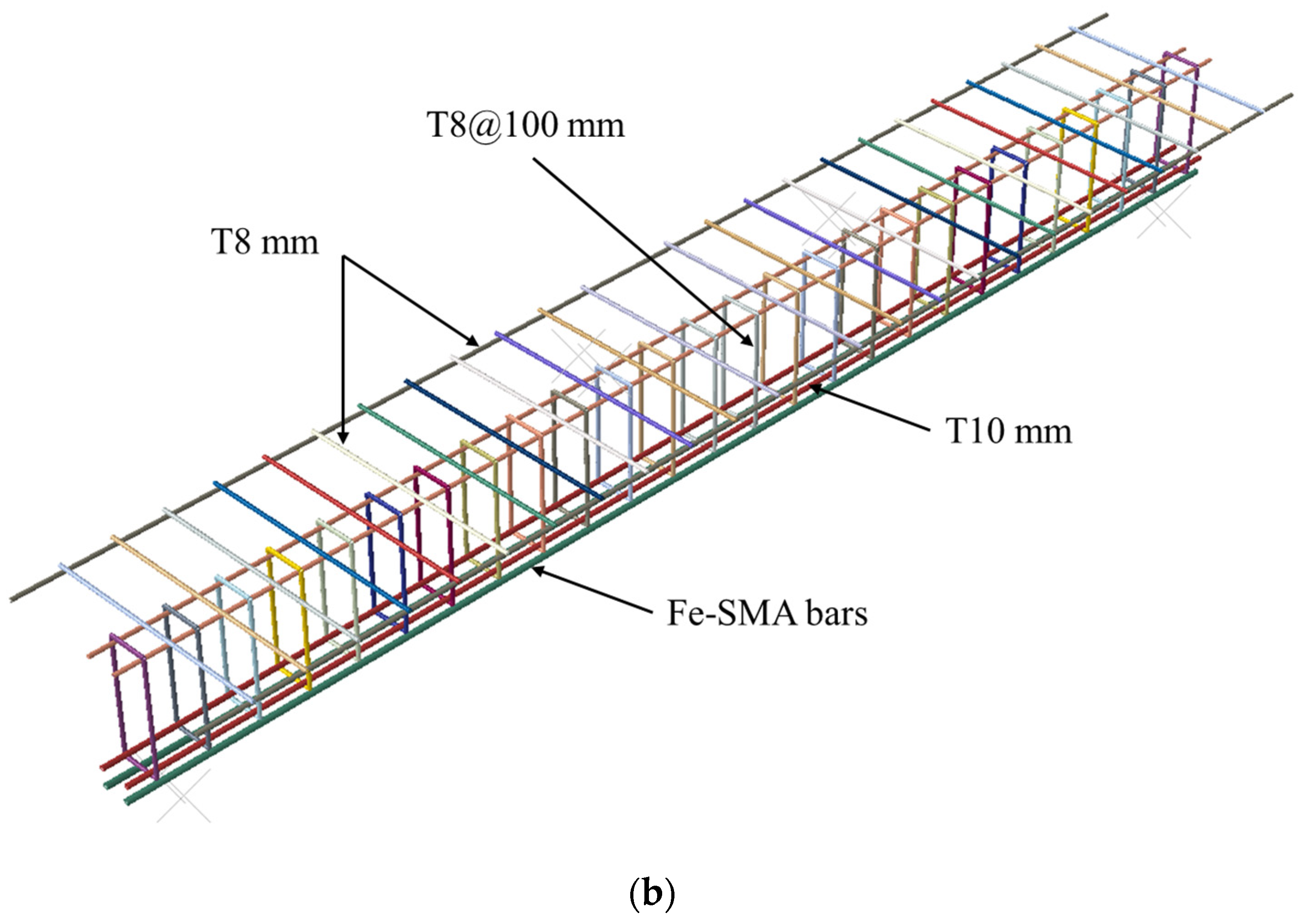
2.1.2. Reinforcement Definition in ABAQUS

A bilinear stress–strain curve is used in ABAQUS to model longitudinal and transversal steel reinforcements covering both elastic and plastic regions. The simulated steel reinforcement’s modulus of elasticity and yield strength are 210 GPa and 508 MPa, respectively [61]. To replicate the elastic response of Fe-SMA bars in ABAQUS, an experimentally derived modulus of elasticity of 133 GPa and a Poisson’s ratio of 0.3 are utilized [61]. The metallurgical composition of Fe-SMA strengthening rebars is Fe-17Mn-5Si-10Cr-4Ni-1 (V, C) based on their mass ratio. Figure 2 illustrates a Shahverdi et al. [61] stress–strain curve for simulating the behavior of Fe-SMA in the absence of built-in ABAQUS models. ABAQUS employs a predefined field to model the pre-stressing effect, with the recovery stress being defined within the field. The stress–strain relationship utilized in this study is comparable to the one adopted in a study conducted by Hong et al. [38]. After stretching the rebars to a pre-strain value (εpre), the tensile force is removed. Meanwhile, a residual strain (εres) is obtained as a result of restoring the elastic and pseudo-elastic strains. When the heating system is activated, the green line in Figure 2 illustrates the recovery stress (σrec) observed in the Fe-SMA rebar. Additionally, Figure 2 depicts the tensile stress reapplied to the Fe-SMA rebar subsequent to loading the beam. The loading process yields a stress–strain curve (blue curve) that closely conforms to the experimental curve (red curve) depicted in Figure 2. Nevertheless, the blue curve exhibits horizontal and vertical stress shifts corresponding to residual strain (εpre) and recovery stress (σrec), respectively.

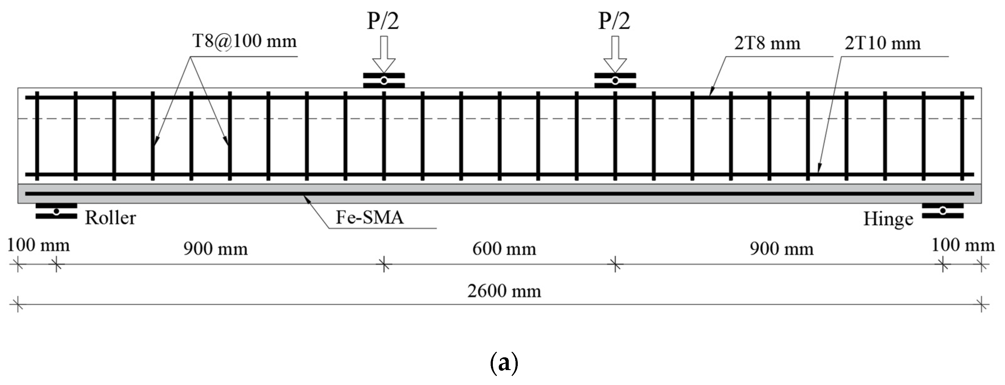
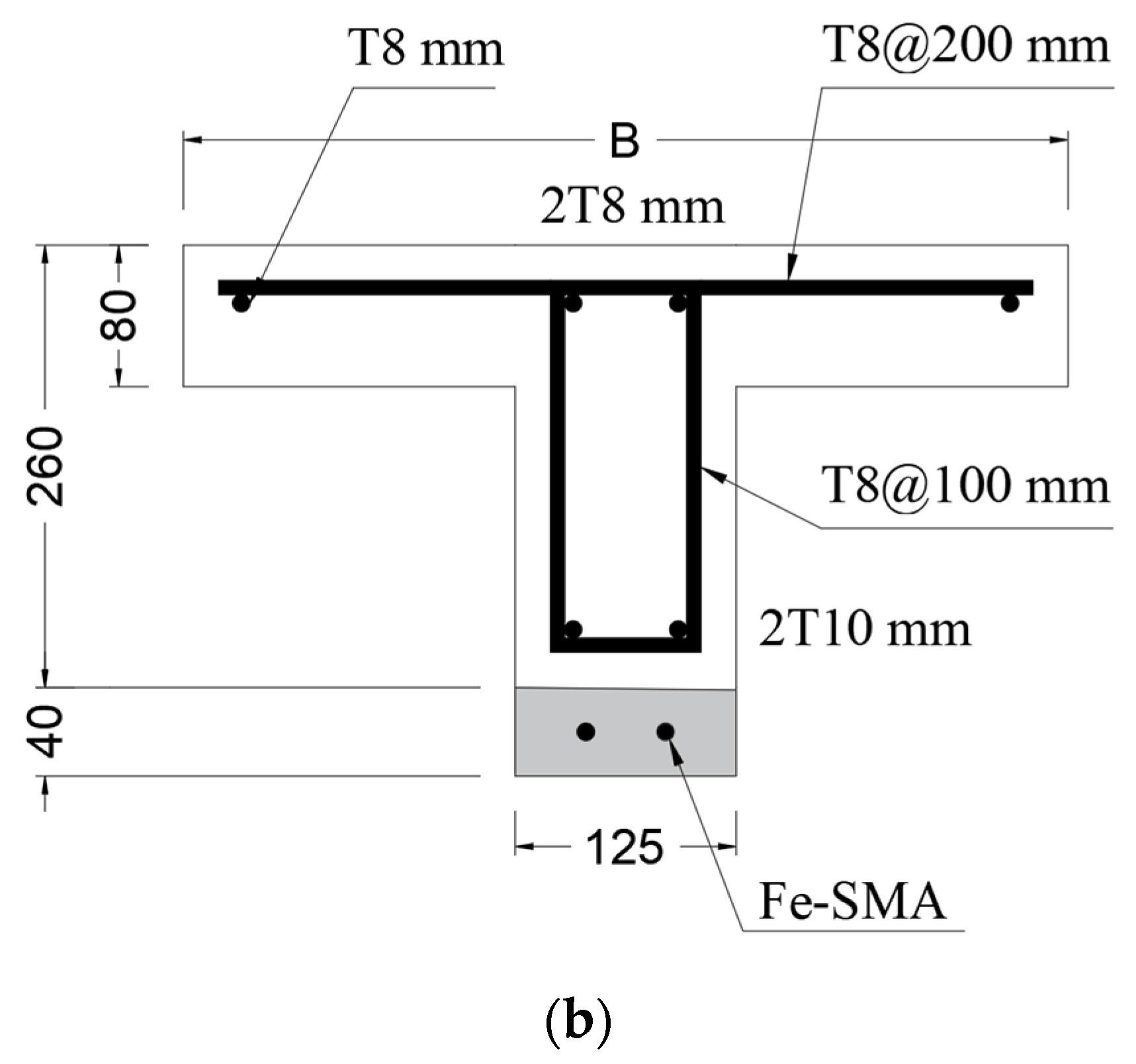
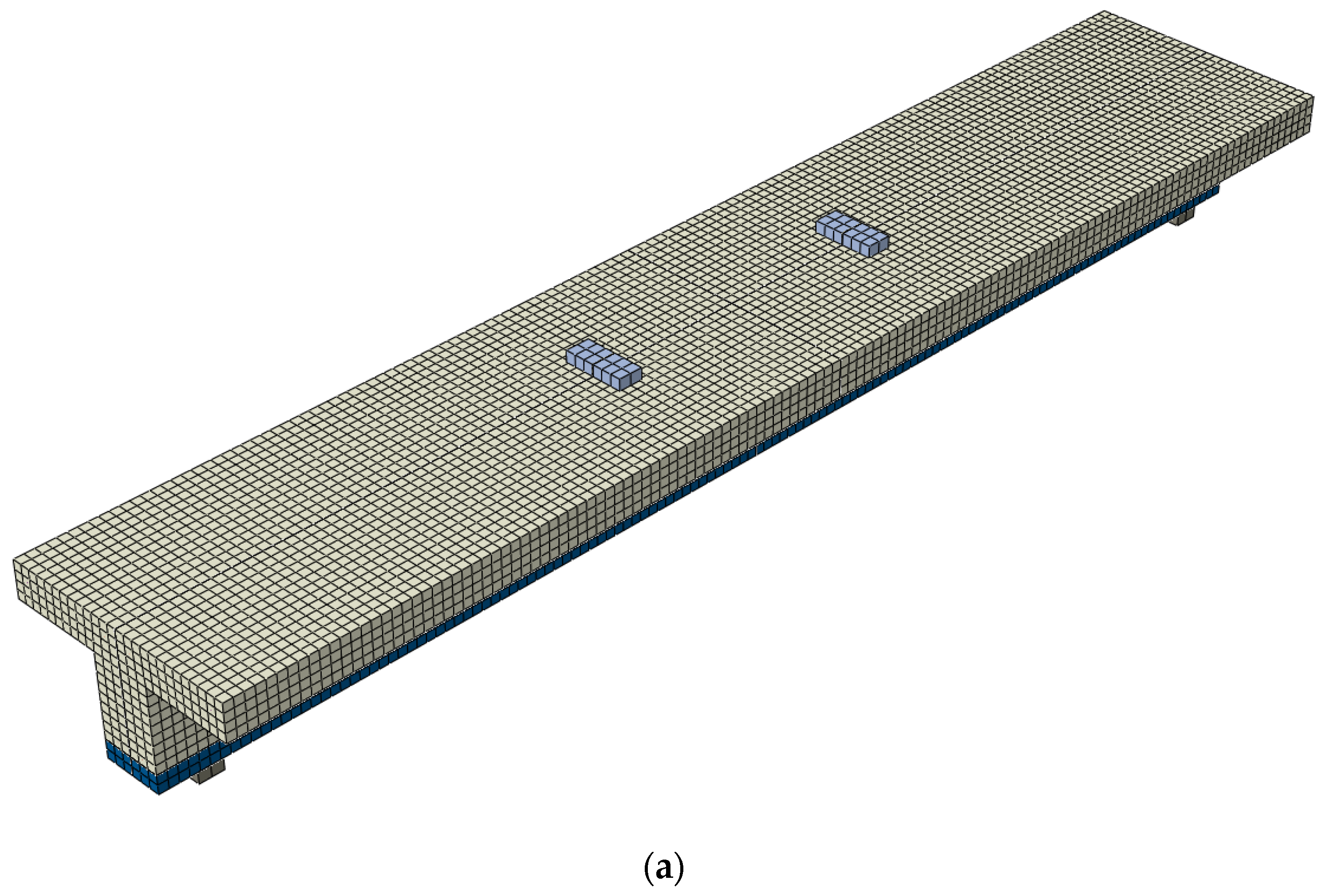
2.2. Geometrical Configuration

The accuracy of the FE modeling is validated by comparing its outcomes with the experimental results obtained by Shahverdi et al. [61]. The authors have presented the verification results in their previous work [62]. Once the FE model has been validated, parametric studies are carried out using ABAQUS to investigate how different parameters impact the structural performance of RC T-beams. Table 3 provides a description of the test parameters, which encompass concrete strength, Fe-SMA bar diameter, and flange width. Table 3 provides information about the grade of concrete, reinforcement ratio, and flange width for each specimen. An example is specimen number (No.) 2, which is identified as C40-2T12-500, indicating that this sample is made of concrete with a grade of 40 MPa, contains two Fe-SMA bars with a diameter of 12 mm, and has a flange width of 500 mm. Figure 3 demonstrates the geometry of the modeled beams and the reinforcement details. A four-point bending scheme [59] is simulated using ABAQUS software. Fe-SMA bars are embedded in a 40 mm thick shotcrete layer, while the beam possesses a total depth of 260 mm and a clear span of 2400 mm. All beams are reinforced with two steel bars, 8 mm for the compression side and 10 mm for the tension side. Additionally, 8 mm steel stirrups are used to reinforce the beams against shear stress, spaced at intervals of 100 mm along the span length.

2.3. Elements Description

As shown in Figure 4a, ABAQUS is used to model the concrete and shotcrete layers using brick elements with eight nodes (C3D8R). The FE element is modeled with hourglass-controlled and reduced integration. Hourglass control uses both the improved strain methods to calculate stiffness coefficients, which does not require a scaling factor. Reducing the integration speeds up the numerical solution by minimizing the number of Gaussian coordinates used to solve the integral. In contrast, a two-node linear 3D truss element (T3D2) was utilized to simulate the reinforcement, which accurately reflected the bars’ axial stiffness (Figure 4b). Plates made of steel as well as concrete and shotcrete layers have been defined using the same criteria. Notably, the model contains three degrees of freedom for each node: x, y, and z translations. All beam parts have been meshed with small element sizes (i.e., 20 mm) in order to ensure high precision and accuracy in results and to prevent convergence issues.

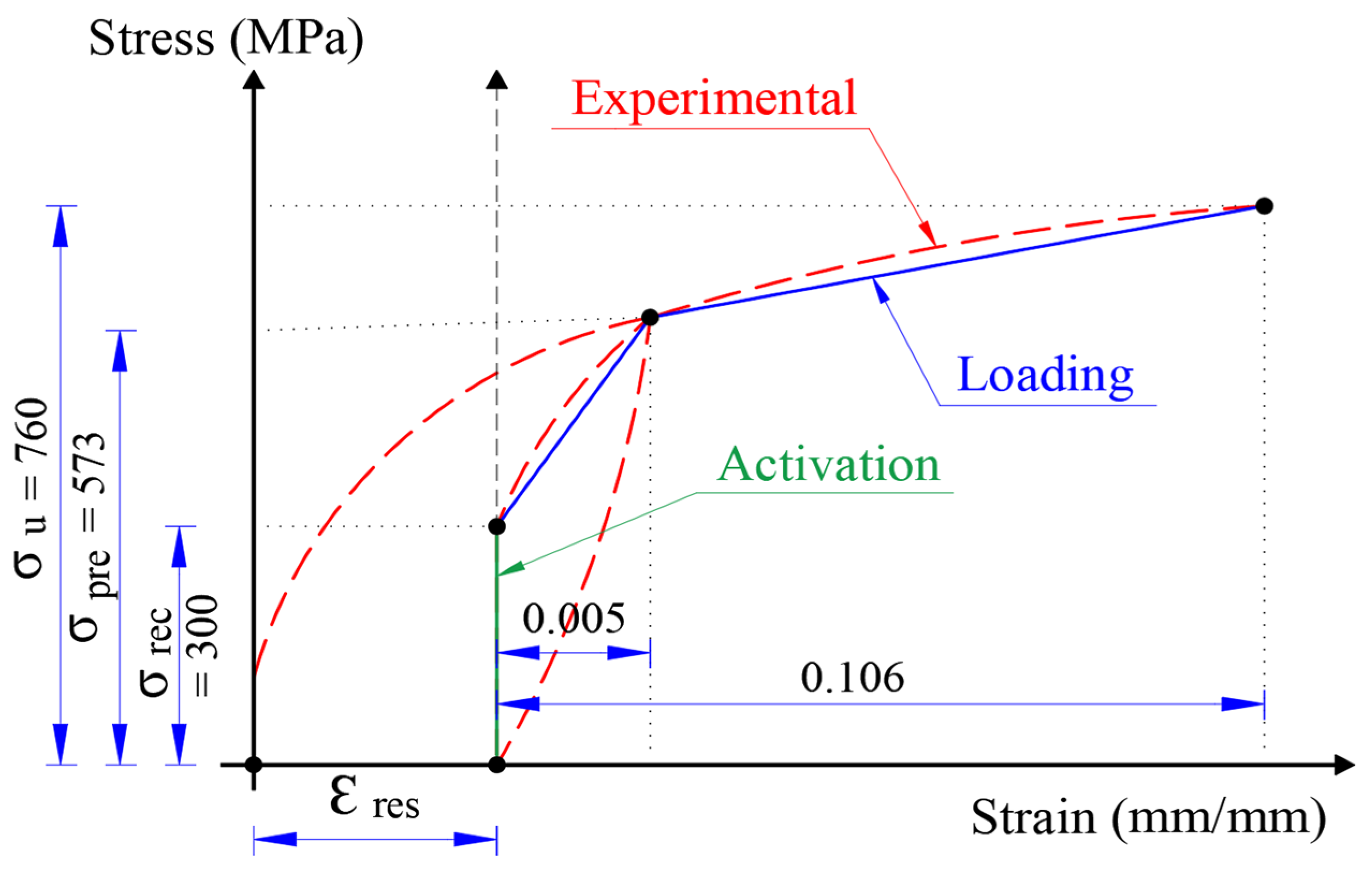
2.4. Pre-Stressing Modeling

A parametric analysis of the present work is based on a single level of pre-stressing: 300 MPa. The predefined field in ABAQUS allows an input of the pre-stressing level to ensure rebars are enforced axially (simulating the activation process of Fe-SMA bars). Afterward, the beam is allowed to settle into equilibrium without any external load, exhibiting a prestress effect as illustrated in Figure 5. The maximum deflection upward was calculated numerically using ABAQUS and compared with the theoretical value, as discussed in the authors’ previous paper [62].

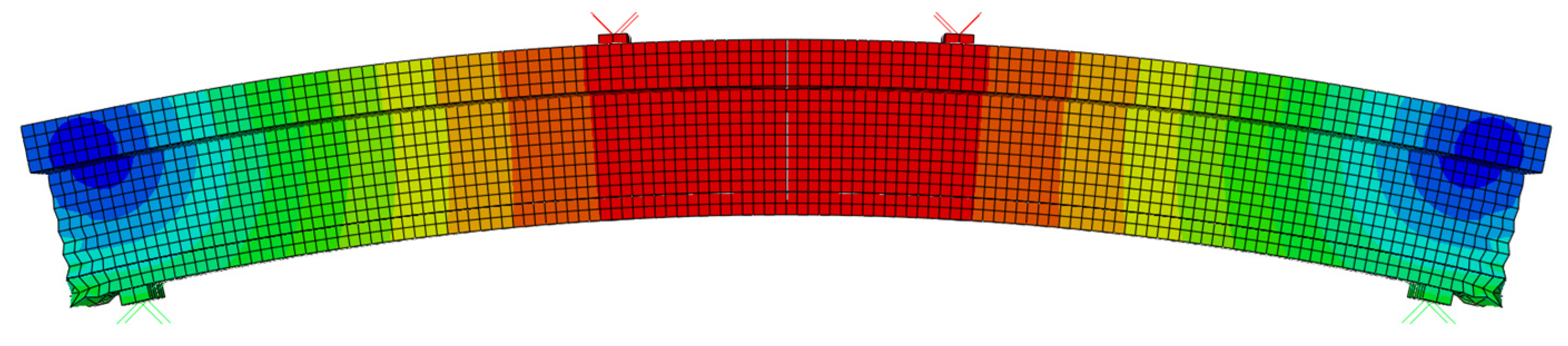
3. Results and Discussion

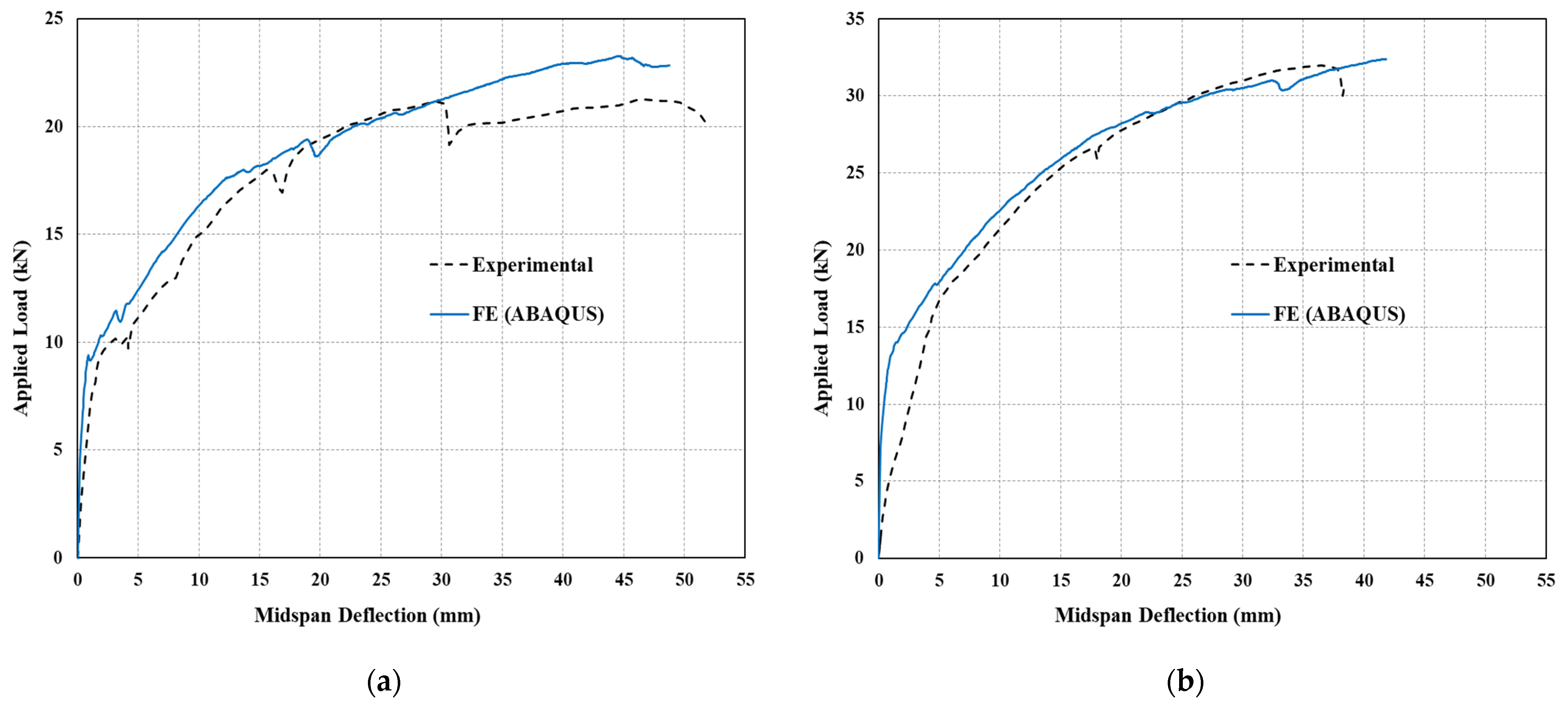
3.1. Evaluating the Accuracy of FE Models

In order to verify the accuracy of the developed FE models, experimental results (beams 10 and 11) from Shahverdi et al. [61] are compared to the FE modeling [61]. Each of the beams 10 and 11 had a cross-sectional dimension of 250 mm by 120 mm and a total length of 2500 mm. Four Fe-SMA bars (8 mm in diameter) were embedded in a shotcrete layer attached to beam 11’s soffit, while beam 10 only used two bars. According to the authors’ previous work [62], the load–deflection curves and crack patterns were validated and showed a good agreement with the experimental findings. However, for clarification purposes, only the load–deflection response verification results are presented in the current study in Figure 6. Although the numerical solution cannot account for all experimental conditions, such as initial thermal microcracks, it is still possible to observe certain discrepancies in the initial loading stages. Additionally, the contact surfaces in the FEA may not exhibit the expected fully bonded behavior under actual experimental conditions. Further details are available in the authors’ previous study [62].

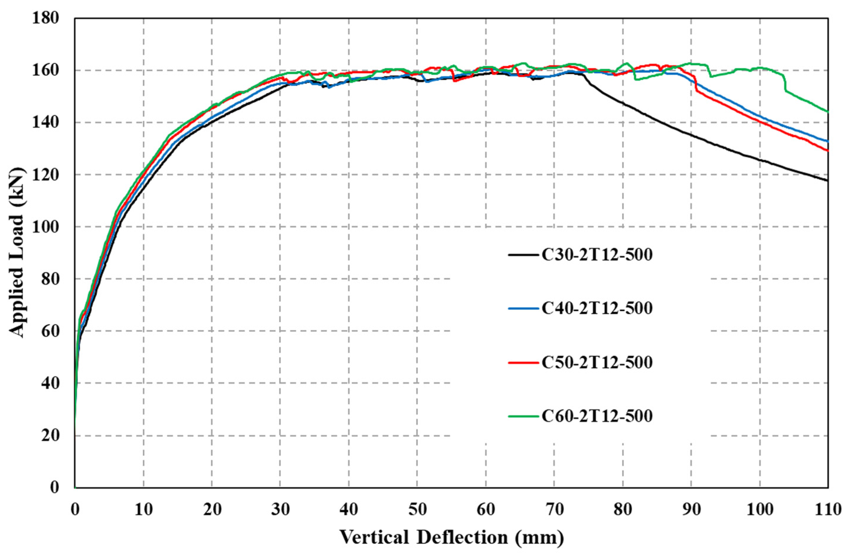
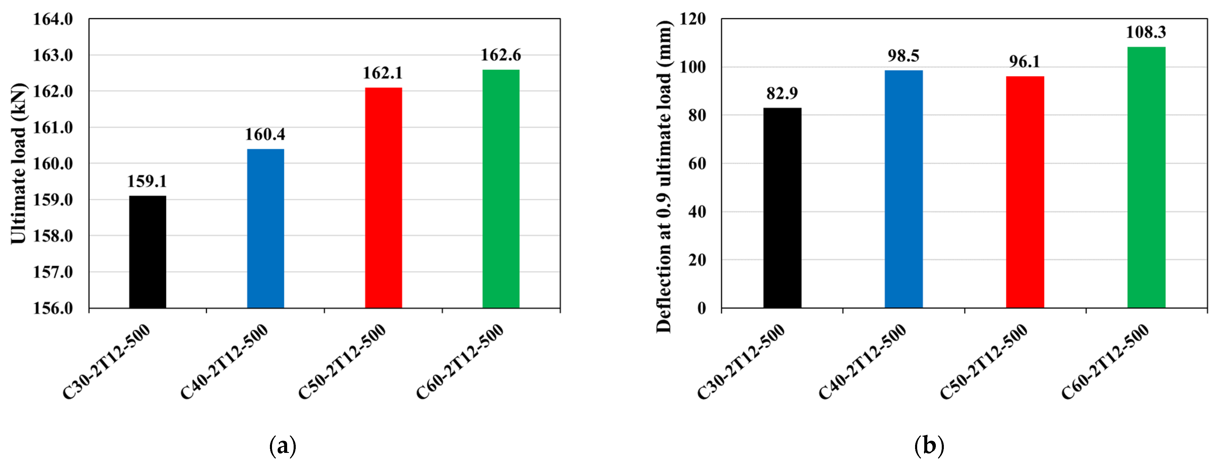
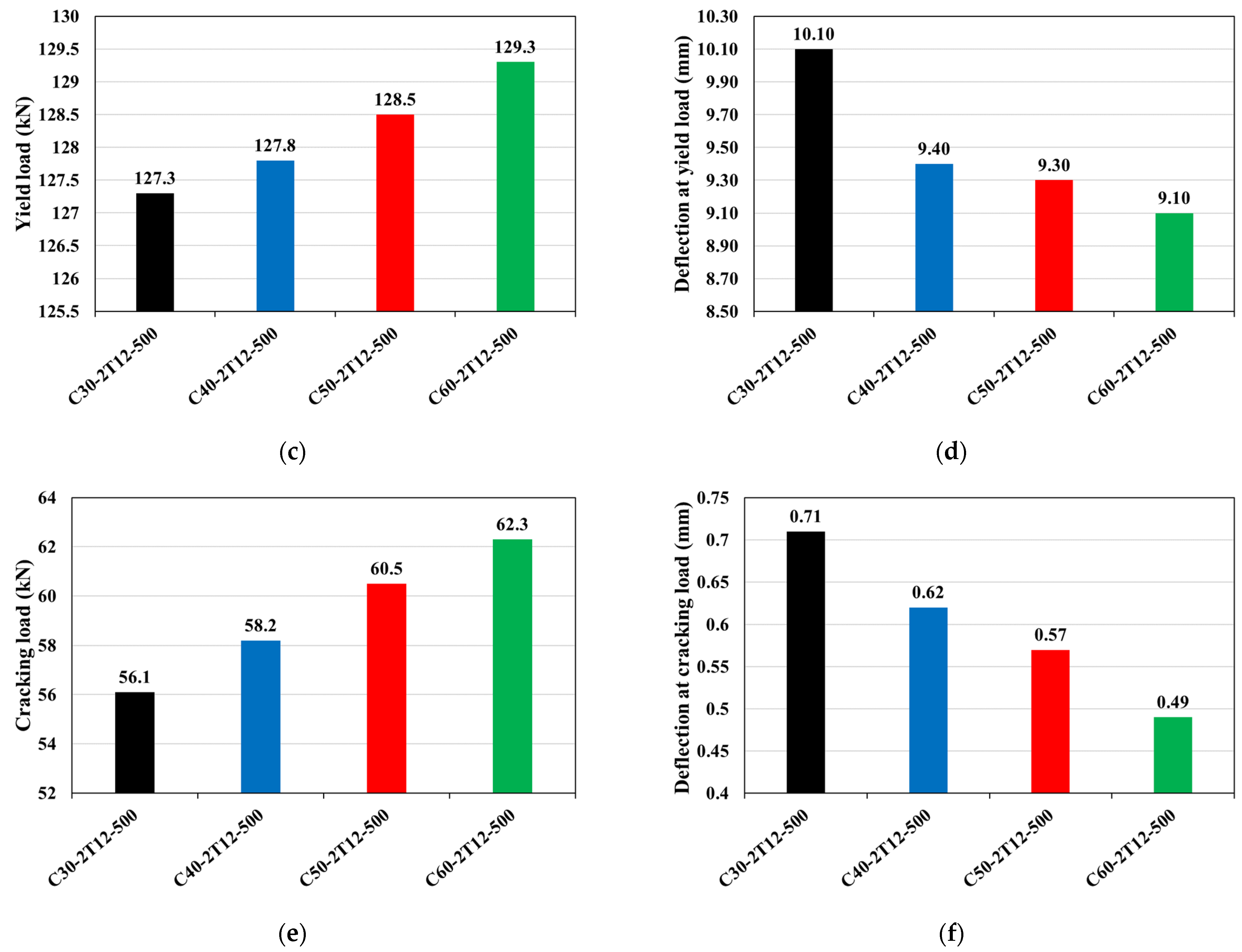
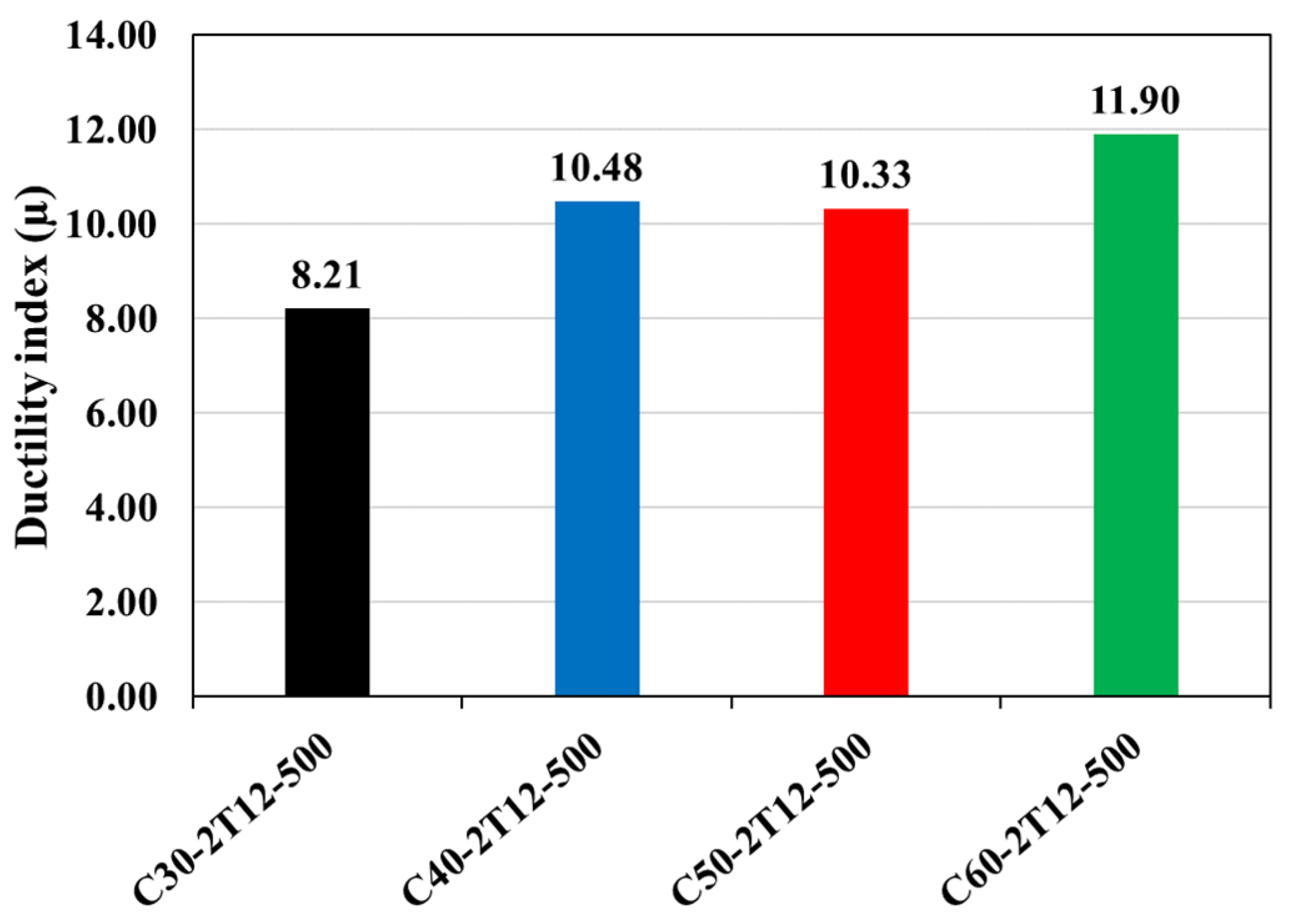
3.2. Influence of Compressive Strength of Concrete ( f c )

The purpose of this section is to investigate the load–deflection response of RC T-beams with different concrete grades (30, 40, 50, and 60 MPa). Meanwhile, the pre-stressing levels and reinforcement ratios of Fe-SMA are maintained at 40% and two bars of 12 mm diameter, respectively. A comparison of the load–deflection relationships between the four numerical models is shown in Figure 7. Curves generally show similar responses except for the hardening part just before failure. The curve has three main parts: the first starts linearly at zero and extends to the cracking load, the second linear relationship extends to the yielding point and has a lower slope. Following the yield point, a nonlinear curve can be noticed up to failure. Table 4 demonstrates the summary results of specimens in this section. Figure 8 compares loads and corresponding deflection values at three stages: cracking, yielding of tension steel bars, and ultimate. It can be noticed that an increase in concrete grade from 30 to 60 MPa results in an increase in cracking, yielding, and ultimate loads of approximately 11%, 2%, and 2%, respectively. At higher loading levels, the depth of the concrete compression block decreases, resulting in a minor contribution from the concrete grade. This could be attributed to the observed effect. Figure 9 demonstrates the ductility index values for the four numerical models. To provide a fair comparison, ductility is determined as the deflection ratio at 10% drop in the peak load to yield load [63]. It is seen that the higher the compressive strength, the higher the ductility of the beam. Notably, increasing the compressive strength of the concrete from 30 to 60 MPa results in a marked improvement in the ductility index, which rises from 8.21 to 11.90, indicating a substantial increase of 45%. The reason for this is that the concrete block’s strength increases on the compression side, causing the neutral axis to shift upwards and away from the balanced neutral axis. Thereby, the concrete cross-section becomes more under-reinforced (i.e., tension failure becomes more likely).

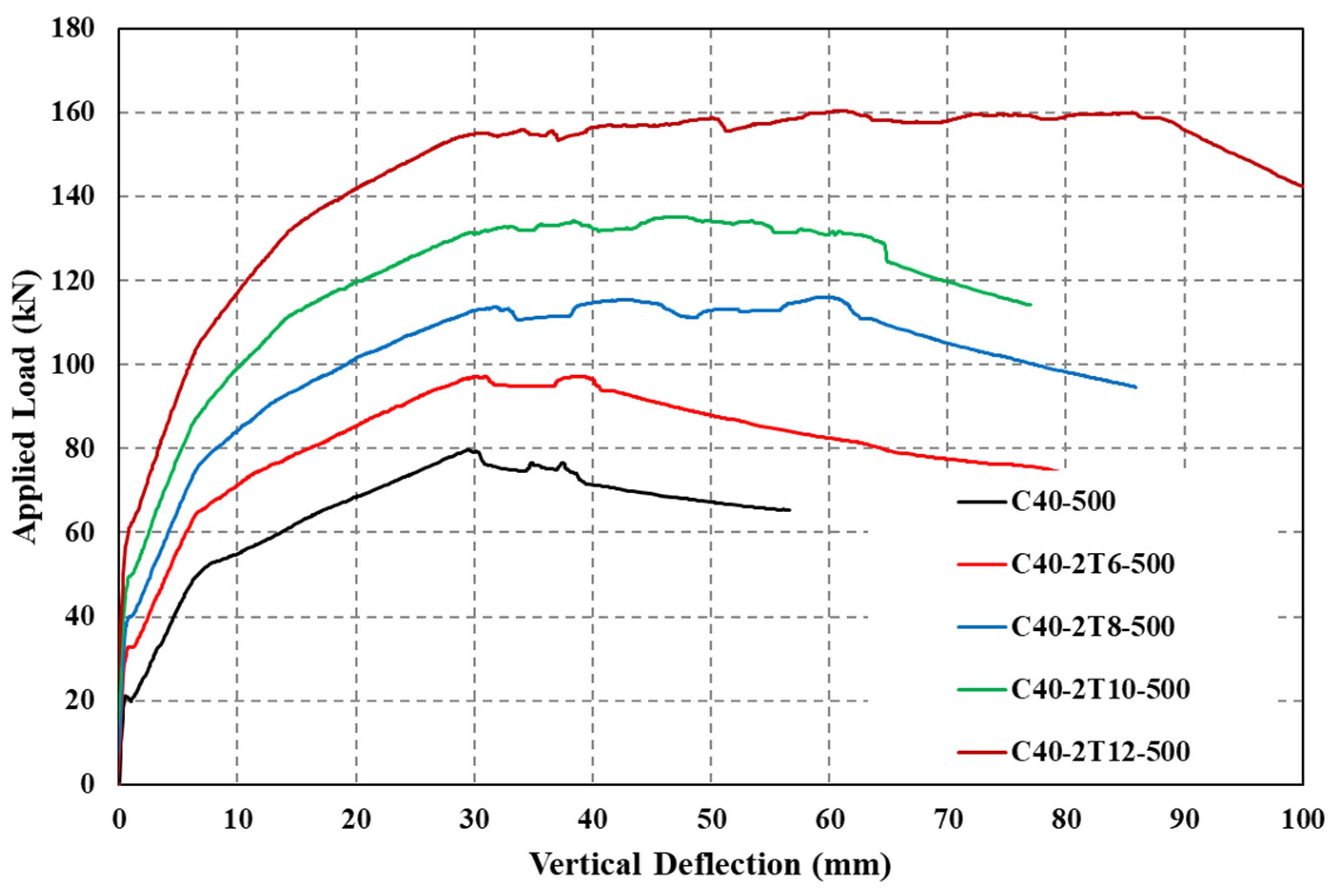
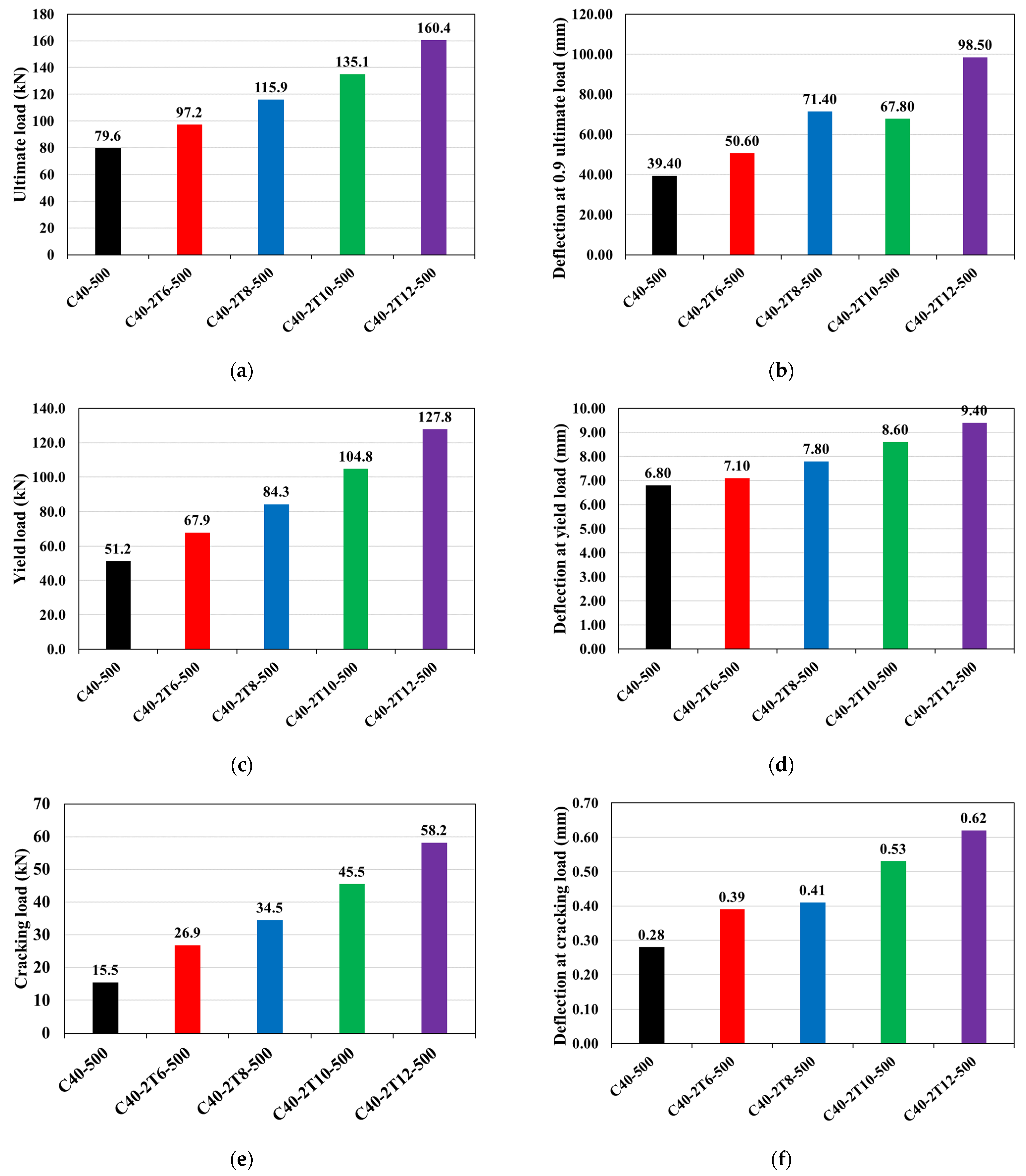
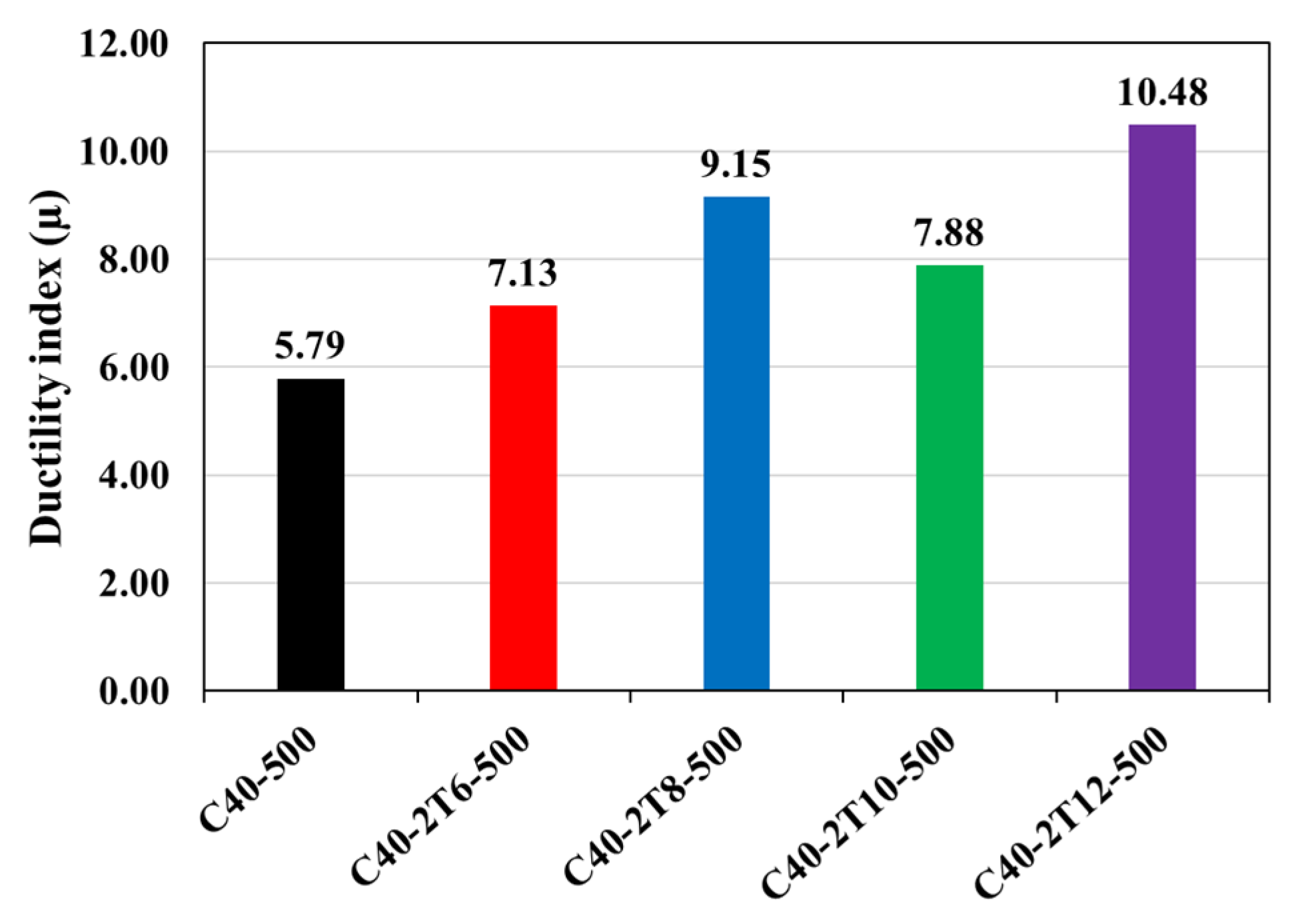
3.3. Effect of Changing the Diameter of Fe-SMA Rebars

The purpose of this section is to examine the load–deflection response of RC beams when different Fe-SMA rebar diameters are used. As outlined in the previous section, the concrete grade, as well as the Fe-SMA prestressing level, remain constant (40 MPa and 40%, respectively). Notably, the recovery force varies with the size of the Fe-SMA bars. Specifically, Fe-SMA bars with diameters of 6, 8, 10, and 12 mm are capable of recovering 8.60, 15.29, 23.86, and 34.35 kN, respectively. The load–deflection behavior of a control beam and four pre-stressed beams with different Fe-SMA rebar diameters (6, 8, 10, and 12 mm) is shown in Figure 10. As aforementioned, the load–deflection relationship could be divided into three main stages (i.e., cracking, yielding of tension steel bars, and ultimate). Table 5 depicts the summary results of specimens in this section. Figure 11 compares the four models with the control beam in terms of ultimate, yielding, and cracking loads and their corresponding deflection values. It is noticed that all pre-stressed beams achieve higher yielding, ultimate, and cracking loads than the control beam. Increasing the diameter of the Fe-SMA rebar results in more significant cracking, yielding, and ultimate loads. For example, raising the diameter from 6 to 12 mm increases the cracking, yielding, and ultimate loads by approximately 116%, 88%, and 65%, respectively. Additionally, it should be noted that larger Fe-SMA rebar diameters are associated with more significant cracking, yielding, and ultimate loads. Likewise, increasing the Fe-SMA diameter enhances the beam’s ductility. As stated in the previous section, the ductility index is calculated based on the ratio of deflection values at 10% drop in the ultimate load to yield load. The Fe-SMA bar pre-stressed beam with a diameter of 12 mm demonstrated the highest ductility index of 10.48, indicating its significant capacity to induce more deformation after reaching its limit. It is worth mentioning that the numerical model of beam C40-2T10-500 surprisingly shows a ductility index slightly lower than C40-2T8-500 (as shown in Figure 12). However, the C40-2T10-500 beam exhibits larger toughness (area under load–deflection curve), indicating higher levels of dissipated energy.

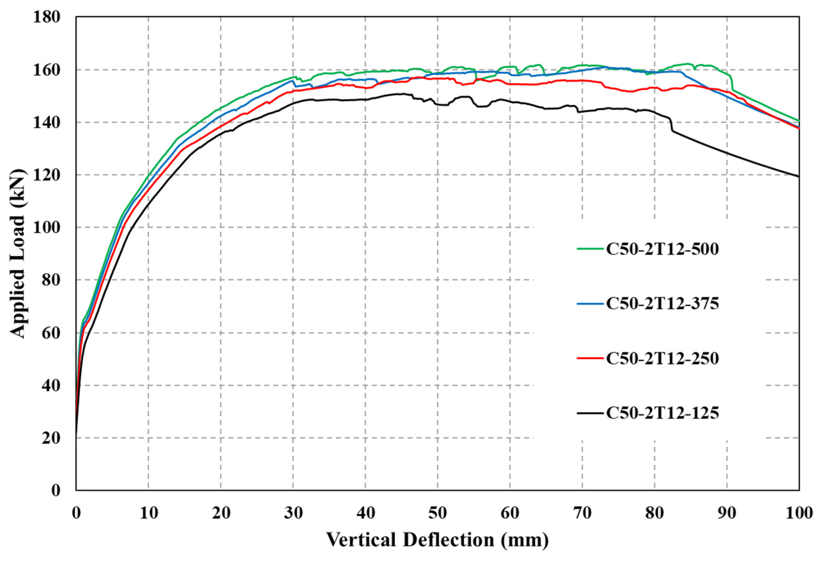
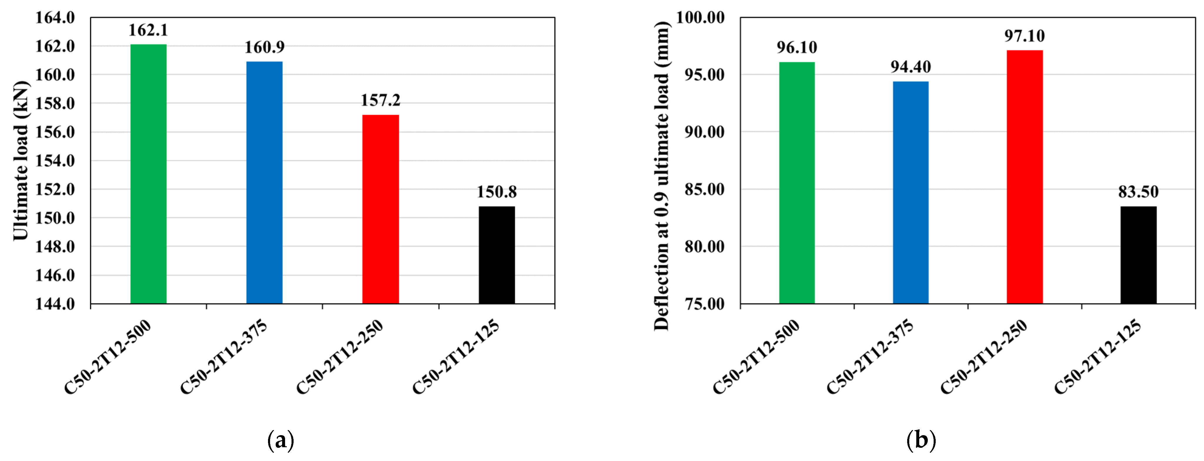
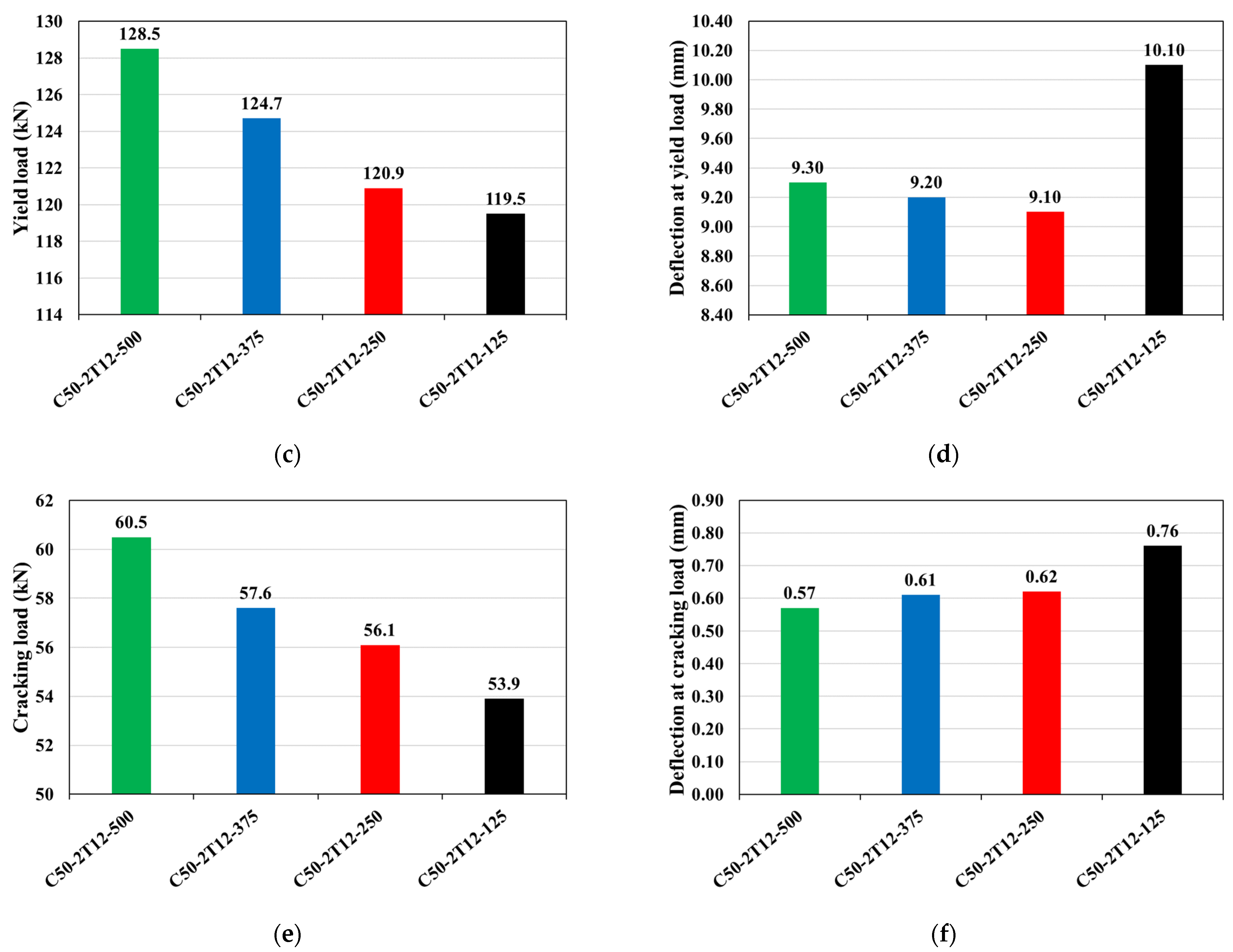
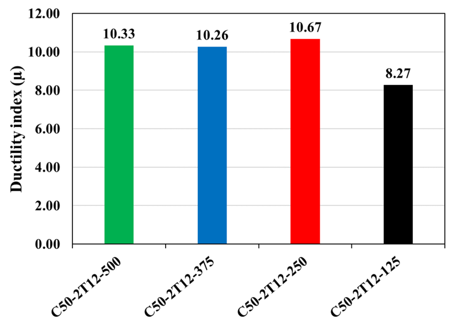
3.4. Effect of Flange Width

The purpose of this section is to demonstrate the effects of flange width on the flexural response of RC T-beams. Four flange widths are used in this study: 500, 375, 250, and 125 mm. The concrete grade and Fe-SMA reinforcement diameter are constant (40 MPa and 12 mm, respectively). Figure 13 exhibits the effect of flange width on the load–deflection relationship. The curves follow the same behavior pattern mentioned in previous sections (i.e., cracking, yielding of tension steel bars, and ultimate). Notably, as the flange width increases, the curves tend to exhibit strain hardening behavior, indicating improved post-yield performance. Figure 14 compares ultimate, yielding, and cracking loads along with their respective deflection values. A reduction in flange width decreases specimen ductility and load-carrying capacity, as seen in Table 6. Specifically, the T-beam with a 500 mm flange width achieved a greater capacity of 7% than the rectangular-sectional (R-sec) beam. Moreover, an increase in the ductility index of 25% is recorded for beams with 500 mm flange width compared to the R-sec beam. Figure 15 depicts a comparison of ductility indexes. These findings align with the observations made by Khatami and Kheyroddin [64], suggesting that considering the compression flange in beam design promotes enhanced ductile behavior. Figure 16 depicts the cracking patterns, where the tension damage in concrete can be observed. It is shown that increasing the flange width distributes more cracks along the beam length. Consequently, T-beams with larger flange widths demonstrate improved deformation capacity and enhanced ductility, effectively providing additional warning signs before eventual failure.

4. Summary and Conclusions

The purpose of this study is to examine the effects of different parameters on the flexural performance of RC T-beams reinforced and pre-stressed with Fe-SMA bars. The numerical findings lead to the following conclusions:
  • Pre-stressed T-beams with greater concrete compressive strength showed a slight improvement in cracking, yielding, and ultimate loads. However, it significantly enhances the ductility of the beam. For instance, changing the compressive strength from 30 to 60 MPa could attain higher cracking, yielding, and ultimate loads of approximately 11%, 2%, and 2%, respectively. While the 60 MPa beam achieved 45% higher ductility than the 30 MPa beam.
  • By substituting 12 mm Fe-SMA bars for 6 mm Fe-SMA bars, the prestressed T-beams showed 65% and 47% stronger strength and improved ductility, respectively.
  • Increasing the flange width of the pre-stressed T-beam enabled the beam to attain higher strength and ductility. Specifically, a 500 mm flange width achieved higher strength and ductility of 7% and 25%, respectively, compared to the pre-stressed rectangular-section beam.
  • This study highly recommends considering the flange of the pre-stressed beam in the flexural design as it significantly affects the beam’s ductility.
It is strongly recommended that further experimental investigations be conducted to validate and complement the methodology and calculations used in the numerical analysis. A deeper understanding of the flexural and shear characteristics of Fe-SMA pre-stressed beams with rectangular and flanged-section shapes would also be highly beneficial. It is highly recommended that further numerical and/or experimental studies are conducted on the analysis of the SMA’s prestress at different temperatures. Moreover, further numerical and/or experimental studies are needed to understand the simultaneous effects of flange width and rebar reinforcement on deflection and stress development in RC T-beams. The authors also recommend studying the use of Fe-SMA reinforcement in shear strengthening as mentioned in [65]. Future studies should investigate the interplay between these factors to provide insights into optimizing design strategies and enhancing the flexural response of T-beams.

Author Contributions

Conceptualization, A.K. and M.E.; methodology, A.K. and M.E.; software, A.K. and M.E.; validation, A.K. and M.E.; formal analysis, A.K. and M.E.; investigation, A.K. and M.E.; resources, A.K., M.E. and W.A.; data curation, A.K. and M.E.; writing—original draft preparation, A.K. and M.E.; writing—review and editing, A.K., M.E., W.A., R.H. and M.A.; visualization, A.K. and M.E.; supervision, W.A., R.H. and M.A.; project administration, W.A., R.H. and M.A.; funding acquisition, W.A., R.H. and M.A. All authors have read and agreed to the published version of the manuscript.

Funding

This research was financially supported by the American University of Sharjah (AUS) through the Ph.D. in Material Science and Engineering (Ph.D.-MSE) Program.

Data Availability Statement

All data are available from the corresponding author upon reasonable request.

Acknowledgments

The authors greatly appreciate the financial support provided by the American University of Sharjah (AUS) through the Ph.D. in Material Science and Engineering (Ph.D.-MSE) Program. This paper represents the opinions of the authors and does not mean to represent the position or opinions of AUS.

Conflicts of Interest

The authors declare no conflict of interest.

References

  1. Khalil, A.E.-H.; Etman, E.; Atta, A.; Essam, M. Nonlinear behavior of RC beams strengthened with strain hardening cementitious composites subjected to monotonic and cyclic loads. Alex. Eng. J. 2016, 55, 1483–1496. [Google Scholar] [CrossRef]
  2. Kunieda, M.; Banno, K. Overlay of RC Bridge Deck Deteriorated by ASR Using an Ultra High Performance-Strain Hardening Cementitious Composite (UHP-SHCC). In Strain Hardening Cementitious Composites: SHCC5; Springer: Berlin/Heidelberg, Germany, 2023; pp. 302–309. [Google Scholar]
  3. Zhu, J.-X.; Xu, L.-Y.; Huang, B.-T.; Weng, K.-F.; Dai, J.-G. Recent developments in Engineered/Strain-Hardening Cementitious Composites (ECC/SHCC) with high and ultra-high strength. Constr. Build. Mater. 2022, 342, 127956. [Google Scholar] [CrossRef]
  4. Khalil, A.E.-H.; Etman, E.; Atta, A.; Essam, M. Behavior of RC beams strengthened with strain hardening cementitious composites (SHCC) subjected to monotonic and repeated loads. Eng. Struct. 2017, 140, 151–163. [Google Scholar] [CrossRef]
  5. Khalil, A.E.-H.; Etman, E.; Atta, A.; Essam, M. Ductility Enhancement of Rc Beams Strengthened With Strain Hardening Cementitious Composites. Proc. Int. Struct. Eng. Constr. 2017, 4, 1–6. [Google Scholar] [CrossRef]
  6. Kim, G.W.; Oh, T.; Lee, S.K.; Banthia, N.; Yoo, D.-Y. Development of Ca-rich slag-based ultra-high-performance fiber-reinforced geopolymer concrete (UHP-FRGC): Effect of sand-to-binder ratio. Constr. Build. Mater. 2023, 370, 130630. [Google Scholar] [CrossRef]
  7. Abadel, A.A.; Abbas, H.; Alshaikh, I.M.; Sennah, K.; Tuladhar, R.; Altheeb, A.; Alamri, M. Experimental study on the effects of external strengthening and elevated temperature on the shear behavior of ultra-high-performance fiber-reinforced concrete deep beams. In Structures; Elsevier: Amsterdam, The Netherlands, 2023; pp. 943–957. [Google Scholar]
  8. Al-Zu’bi, H.; Abdel-Jaber, M.; Katkhuda, H. Flexural Strengthening of Reinforced Concrete Beams with Variable Compressive Strength Using Near-Surface Mounted Carbon-Fiber-Reinforced Polymer Strips [NSM-CFRP]. Fibers 2022, 10, 86. [Google Scholar] [CrossRef]
  9. Aljidda, O.; El Refai, A.; Alnahhal, W. Comparative study on the bond performance of near-surface mounted fiber-reinforced polymer bars. Constr. Build. Mater. 2023, 364, 129923. [Google Scholar] [CrossRef]
  10. Effiong, J.U.; Ede, A.N. Experimental Investigation on the Strengthening of Reinforced Concrete Beams Using Externally Bonded and Near-Surface Mounted Natural Fibre Reinforced Polymer Composites—A Review. Materials 2022, 15, 5848. [Google Scholar] [CrossRef]
  11. Su, M.; Gong, S.; Liu, Y.; Peng, H. Flexural behavior of RC beams strengthened with fully or partially prestressed near-surface mounted FRP strips: An experimental investigation. Eng. Struct. 2022, 262, 114345. [Google Scholar] [CrossRef]
  12. RHawileh, R.A.; El-Maaddawy, T.A.; Naser, M.Z. Nonlinear finite element modeling of concrete deep beams with openings strengthened with externally-bonded composites. Mater. Des. 2012, 42, 378–387. [Google Scholar] [CrossRef]
  13. El-Maaddawy, T.; Ismail, E.S. Three-Dimensional Finite Element Modeling of Nsm-Cfrp Strengthened Continuous Concrete Slab Strips Containing Cut-Outs. In Infrastructure Management, Assessment and Rehabilitation; Cambridge Scholars Publishing: Newcastle upon Tyne, UK, 2021; p. 135. [Google Scholar]
  14. Mansour, M.; El-Maaddawy, T. Testing and modeling of deep beams strengthened with NSM-CFRP reinforcement around cutouts. Case Stud. Constr. Mater. 2021, 15, e00670. [Google Scholar] [CrossRef]
  15. Abdalla, J.A.; Abokwiek, R.; Hawileh, R.A. Models for Predicting Strength of RC Columns Strengthened with NSM-CFRP Strips and CFRP-Fabric Wraps. Procedia Struct. Integr. 2022, 37, 660–667. [Google Scholar] [CrossRef]
  16. Hawileh, R.A.; Saleh, R.B.; Saqan, E.I.; Abdalla, J.A. Contribution of Longitudinal NSM-CFRP Bars on the Shear Strength of RC Beams with Varying Depths and Concrete Strengths. J. Compos. Constr. 2022, 26, 04022025. [Google Scholar] [CrossRef]
  17. Youssf, O.; Hassanli, R.; Mills, J.E. Retrofitting square columns using FRP-confined crumb rubber concrete to improve confinement efficiency. Constr. Build. Mater. 2017, 153, 146–156. [Google Scholar] [CrossRef]
  18. Sabzi, J.; Esfahani, M.R.; Ozbakkaloglu, T.; Farahi, B. Effect of concrete strength and longitudinal reinforcement arrangement on the performance of reinforced concrete beams strengthened using EBR and EBROG methods. Eng. Struct. 2020, 205, 110072. [Google Scholar] [CrossRef]
  19. Gholampour, A.; Hassanli, R.; Mills, J.E.; Vincent, T.; Kunieda, M. Experimental investigation of the performance of concrete columns strengthened with fiber reinforced concrete jacket. Constr. Build. Mater. 2018, 194, 51–61. [Google Scholar] [CrossRef]
  20. Hassanli, R.; Youssf, O.; Mills, J.E. Seismic Performance of Precast Posttensioned Segmental FRP-Confined and Unconfined Crumb Rubber Concrete Columns. J. Compos. Constr. 2017, 21, 04017006. [Google Scholar] [CrossRef]
  21. Mhanna, H.H.; Hawileh, R.A.; Abdalla, J.A. Comparative analysis of design guidelines for FRP contribution to shear capacity of strengthened RC beams. Procedia Struct. Integr. 2022, 37, 359–366. [Google Scholar] [CrossRef]
  22. Hawileh, R.A.; Al Nuaimi, N.; Nawaz, W.; Abdalla, J.A.; Sohail, M.G. Flexural and Bond Behavior of Concrete Beams Strengthened with CFRP and Galvanized Steel Mesh Laminates. Pract. Period. Struct. Des. Constr. 2022, 27, 04021068. [Google Scholar] [CrossRef]
  23. Mhanna, H.H.; Hawileh, R.A.; Al Rashed, A.; Abdalla, J.A. Performance of RC beams externally strengthened with hybrid CFRP and PET-FRP laminates. Procedia Struct. Integr. 2022, 42, 1190–1197. [Google Scholar] [CrossRef]
  24. Mhanna, H.H.; Hawileh, R.A.; Abdalla, J.A. Shear behavior of RC T-beams externally strengthened with anchored high modulus carbon fiber-reinforced polymer (CFRP) laminates. Compos. Struct. 2021, 272, 114198. [Google Scholar] [CrossRef]
  25. Abuodeh, O.R.; Abdalla, J.A.; Hawileh, R.A. Prediction of shear strength and behavior of RC beams strengthened with externally bonded FRP sheets using machine learning techniques. Compos. Struct. 2019, 234, 111698. [Google Scholar] [CrossRef]
  26. Bazli, M.; Abolfazli, M. Mechanical Properties of Fibre Reinforced Polymers under Elevated Temperatures: An Overview. Polymers 2020, 12, 2600. [Google Scholar] [CrossRef] [PubMed]
  27. Feng, P.; Wang, J.; Tian, Y.; Loughery, D.; Wang, Y. Mechanical Behavior and Design of FRP Structural Members at High and Low Service Temperatures. J. Compos. Constr. 2016, 20, 04016021. [Google Scholar] [CrossRef]
  28. Meng, J.; Wang, Y.; Yang, H.; Wang, P.; Lei, Q.; Shi, H.; Lei, H.; Fang, D. Mechanical properties and internal microdefects evolution of carbon fiber reinforced polymer composites: Cryogenic temperature and thermocycling effects. Compos. Sci. Technol. 2020, 191, 108083. [Google Scholar] [CrossRef]
  29. Hosseini, A.; Michels, J.; Izadi, M.; Ghafoori, E. A comparative study between Fe-SMA and CFRP reinforcements for prestressed strengthening of metallic structures. Constr. Build. Mater. 2019, 226, 976–992. [Google Scholar] [CrossRef]
  30. Youssef, M.A.; Alam, M.S.; Nehdi, M. Experimental Investigation on the Seismic Behavior of Beam-Column Joints Reinforced with Superelastic Shape Memory Alloys. J. Earthq. Eng. 2008, 12, 1205–1222. [Google Scholar] [CrossRef]
  31. Sidharth, R.; Abuzaid, W.; Vollmer, M.; Niendorf, T.; Sehitoglu, H. Fatigue Crack Initiation in the Iron-Based Shape Memory Alloy FeMnAlNiTi. Shape Mem. Superelasticity 2020, 6, 323–331. [Google Scholar] [CrossRef]
  32. Raza, S.; Shafei, B.; Saiidi, M.S.; Motavalli, M.; Shahverdi, M. Shape memory alloy reinforcement for strengthening and self-centering of concrete structures—State of the art. Constr. Build. Mater. 2022, 324, 126628. [Google Scholar] [CrossRef]
  33. Salunkhe, P.; Agawane, P.; Chaudhari, D.; Patil, S. Experimental and Analytical Study of Shape Memory Alloy in Civil Structures—A Review. In Smart Technologies for Energy, Environment and Sustainable Development, Vol 1: Select Proceedings of ICSTEESD 2020; Springer: Singapore, 2022; pp. 81–89. [Google Scholar]
  34. Zhang, Z.-X.; Zhang, J.; Wu, H.; Ji, Y.; Kumar, D.D. Iron-based shape memory alloys in construction: Research, applications and opportunities. Materials 2022, 15, 1723. [Google Scholar] [CrossRef]
  35. Qiang, X.; Chen, L.; Jiang, X. Achievements and Perspectives on Fe-Based Shape Memory Alloys for Rehabilitation of Reinforced Concrete Bridges: An Overview. Materials 2022, 15, 8089. [Google Scholar] [CrossRef] [PubMed]
  36. Sohn, J.W.; Ruth, J.S.; Yuk, D.-G.; Choi, S.-B. Application of Shape Memory Alloy Actuators to Vibration and Motion Control of Structural Systems: A Review. Appl. Sci. 2023, 13, 995. [Google Scholar] [CrossRef]
  37. Khalil, A.E.-H.; Etman, E.; Atta, A.; Essam, M. Strengthening of RC beams subjected to cyclic load using ultra high-performance strain hardening cementitious composites. In Proceedings of the International Structural Engineering and Construction, ISEC, Valencia, Spain, 24–29 July 2017. [Google Scholar] [CrossRef]
  38. Hong, K.; Lee, S.; Yeon, Y.; Jung, K. Flexural Response of Reinforced Concrete Beams Strengthened with Near-Surface-Mounted Fe-Based Shape-Memory Alloy Strips. Int. J. Concr. Struct. Mater. 2018, 12, 45. [Google Scholar] [CrossRef]
  39. Ruiz-Pinilla, J.G.; Montoya-Coronado, L.A.; Ribas, C.; Cladera, A. Finite element modeling of RC beams externally strengthened with iron-based shape memory alloy (Fe-SMA) strips, including analytical stress-strain curves for Fe-SMA. Eng Struct. 2020, 223, 111152. [Google Scholar] [CrossRef]
  40. Shahverdi, M.; Czaderski, C.; Motavalli, M. Iron-based shape memory alloys for prestressed near-surface mounted strengthening of reinforced concrete beams. Constr. Build. Mater. 2016, 112, 28–38. [Google Scholar] [CrossRef]
  41. Cladera, A.; Montoya-Coronado, L.A.; Ruiz-Pinilla, J.G.; Ribas, C. Shear strengthening of slender reinforced concrete T-shaped beams using iron-based shape memory alloy strips. Eng. Struct. 2020, 221, 111018. [Google Scholar] [CrossRef]
  42. Czaderski, C.; Shahverdi, M.; Michels, J. Iron based shape memory alloys as shear reinforcement for bridge girders. Constr. Build. Mater. 2020, 274, 121793. [Google Scholar] [CrossRef]
  43. Elkafrawy, M.; Alashkar, A.; Hawileh, R.; AlHamaydeh, M. FEA Investigation of Elastic Buckling for Functionally Graded Material (FGM) Thin Plates with Different Hole Shapes under Uniaxial Loading. Buildings 2022, 12, 802. [Google Scholar] [CrossRef]
  44. Karzad, A.S.; Al-Sadoon, Z.A.; Sagheer, A.; AlHamaydeh, M. Experimental and Nonlinear Finite Element Analysis Data for an Innovative Buckling Restrained Bracing System to Rehabilitate Seismically Deficient Structures. Data 2022, 7, 171. [Google Scholar] [CrossRef]
  45. AlHamaydeh, M.; Elkafrawy, M.E.; Amin, F.M.; Maky, A.M.; Mahmoudi, F. Analysis and Design of UHPC Tall Buildings in UAE with Ductile Coupled Shear Walls Lateral Load Resisting System. In Proceedings of the 2022 Advances in Science and Engineering Technology International Conferences (ASET), Dubai, United Arab Emirates, 21–24 February 2022; pp. 1–6. [Google Scholar] [CrossRef]
  46. Alashkar, A.; Elkafrawy, M.; Hawileh, R.; AlHamaydeh, M. Buckling Analysis of Functionally Graded Materials (FGM) Thin Plates with Various Circular Cutout Arrangements. J. Compos. Sci. 2022, 6, 27. [Google Scholar] [CrossRef]
  47. Markou, G.; AlHamaydeh, M. 3D Finite Element Modeling of GFRP-Reinforced Concrete Deep Beams without Shear Reinforcement. Int. J. Comput. Methods 2017, 15, 1850001. [Google Scholar] [CrossRef]
  48. Alhamaydeh, M.; Elayyan, L. Impact of diverse seismic hazard estimates on design and performance of Steel Plate Shear Walls buildings in Dubai, UAE. In Proceedings of the 2017 7th International Conference on Modeling, Simulation, and Applied Optimization, ICMSAO 2017, Sharjah, United Arab Emirates, 4–6 April 2017; pp. 1–3. [Google Scholar] [CrossRef]
  49. AlHamaydeh, M.; Sagher, A. Key parameters influencing the behavior of Steel Plate Shear Walls (SPSW). In Proceedings of the 2017 7th International Conference on Modeling, Simulation, and Applied Optimization (ICMSAO), Sharjah, United Arab Emirates, 4–6 April 2017; pp. 1–6. [Google Scholar] [CrossRef]
  50. AlHamaydeh, M.; Elkafrawy, M.; Banu, S. Seismic Performance and Cost Analysis of UHPC Tall Buildings in UAE with Ductile Coupled Shear Walls. Materials 2022, 15, 2888. [Google Scholar] [CrossRef] [PubMed]
  51. AlHamaydeh, M.; Elkafrawy, M.E.; Aswad, N.G.; Talo, R.; Banu, S. Evaluation of UHPC Tall Buildings in UAE with Ductile Coupled Shear Walls under Seismic Loading. In Proceedings of the 2022 Advances in Science and Engineering Technology International Conferences (ASET), Dubai, United Arab Emirates, 21–24 February 2022; pp. 1–6. [Google Scholar] [CrossRef]
  52. Debski, H.; Rozylo, P.; Wysmulski, P. Stability and load-carrying capacity of short open-section composite columns under eccentric compression loading. Compos. Struct. 2020, 252, 112716. [Google Scholar] [CrossRef]
  53. Kopuri, N.A.G.K.M.; Priyadharshani, S.A. Numerical analysis of concrete filled steel tube columns using ABAQUS. Mater. Today Proc. 2022, 65, 3476–3482. [Google Scholar] [CrossRef]
  54. AlHamaydeh, M.; Elkafrawy, M.E.; Kyaure, M.; Elyas, M.; Uwais, F. Cost Effectiveness of UHPC Ductile Coupled Shear Walls for High-Rise Buildings in UAE Subjected to Seismic Loading. In Proceedings of the 2022 Advances in Science and Engineering Technology International Conferences (ASET), Dubai, United Arab Emirates, 21–24 February 2022; pp. 1–6. [Google Scholar] [CrossRef]
  55. Yeon, Y.-M.; Lee, W.; Hong, K.-N. Finite Element Analysis of Reinforced Concrete Beams Prestressed by Fe-Based Shape Memory Alloy Bars. Appl. Sci. 2022, 12, 3255. [Google Scholar] [CrossRef]
  56. Elkafrawy, M.E.; Khalil, A.M.; Abuzaid, W.; Hawileh, R.A.; AlHamaydeh, M. Nonlinear Finite Element Analysis (NLFEA) of Pre-stressed RC Beams Reinforced with Iron-Based Shape Memory Alloy (Fe-SMA). In Proceedings of the 2022 Advances in Science and Engineering Technology International Conferences (ASET), Dubai, United Arab Emirates, 21–24 February 2022; pp. 1–7. [Google Scholar]
  57. Yeon, Y.-M.; Hong, K.-N.; Lee, S.; Ji, S.-W. Numerical Study of RC Beams Strengthened with Fe-Based Shape Memory Alloy Strips Using the NSM Method. Appl. Sci. 2021, 11, 6809. [Google Scholar] [CrossRef]
  58. Smith, M. ABAQUS/Standard User’s Manual, Version 6.9; Dassault Systèmes Simulia Corp.: Providence, RI, USA, 2009. [Google Scholar]
  59. ASTM. Standard test methods for flexural properties of unreinforced and reinforced plastics and electrical insulating materials. In Annual Book of ASTM Standards; ASTM D790; ASTM: West Conshohocken, PA, USA, 1997. [Google Scholar]
  60. Hafezolghorani, M.; Hejazi, F.; Vaghei, R.; Jaafar, M.S.B.; Karimzade, K. Simplified Damage Plasticity Model for Concrete. Struct. Eng. Int. 2017, 27, 68–78. [Google Scholar] [CrossRef]
  61. Shahverdi, M.; Czaderski, C.; Annen, P.; Motavalli, M. Strengthening of RC beams by iron-based shape memory alloy bars embedded in a shotcrete layer. Eng. Struct. 2016, 117, 263–273. [Google Scholar] [CrossRef]
  62. Khalil, A.; Elkafrawy, M.; Abuzaid, W.; Hawileh, R.; AlHamaydeh, M. Flexural Performance of RC Beams Strengthened with Pre-Stressed Iron-Based Shape Memory Alloy (Fe-SMA) Bars: Numerical Study. Buildings 2022, 12, 2228. [Google Scholar] [CrossRef]
  63. Olivia, M.; Mandal, P. Curvature Ductility of Reinforced Concrete Beam. J. Civ. Eng. 2005, 6, 1–13. [Google Scholar]
  64. Khatami, S.; Kheyroddin, A. The Effect of Flange Thickness on the Behavior of Flanged-Section Shear Walls. Procedia Eng. 2011, 14, 2994–3000. [Google Scholar] [CrossRef] [Green Version]
  65. Elkafrawy, M.; Khalil, A.; AlHamaydeh, M.; Hawileh, R.; Abuzaid, W. Enhancing the Shear Capacity of RC Beams with Web Openings in Shear Zones Using Pre-Stressed Fe-SMA Bars: Numerical Study. Buildings 2023, 13, 1505. [Google Scholar] [CrossRef]
Figure 1. Concrete response to uniaxial (a) compression and (b) tensile loading.
Jcs 07 00258 g001
Figure 2. Stress–strain relationship of Fe-SMA bars.
Jcs 07 00258 g002
Figure 3. Beam geometry and reinforcement details. (a) Four-point loading test setup, (b) Beam’s cross-sectional details.
Jcs 07 00258 g003aJcs 07 00258 g003b
Figure 4. Mesh configuration in ABAQUS: (a) concrete and (b) steel.
Jcs 07 00258 g004aJcs 07 00258 g004b
Figure 5. Pre-stressing effect in ABAQUS (deformed shape).
Jcs 07 00258 g005
Figure 6. Verification results from authors’ previous work [62] for (a) beam 10 and (b) beam 11.
Jcs 07 00258 g006
Figure 7. Effect of f c on the load–deflection response.
Jcs 07 00258 g007
Figure 8. Comparison of loads and corresponding deflection values at (a,b) ultimate, (c,d) yield, and (e,f) cracking.
Jcs 07 00258 g008aJcs 07 00258 g008b
Figure 9. Comparison of ductility index values.
Jcs 07 00258 g009
Figure 10. Response of Fe-SMA rebar to load–deflection response as a function of Fe-SMA diameter.
Jcs 07 00258 g010
Figure 11. Comparison of loads and corresponding deflection values at (a,b) ultimate, (c,d) yield, and (e,f) cracking.
Jcs 07 00258 g011
Figure 12. Comparison of ductility index values.
Jcs 07 00258 g012
Figure 13. Effect of flange width on load–deflection response.
Jcs 07 00258 g013
Figure 14. Comparison of loads and corresponding deflection values at (a,b) ultimate, (c,d) yield, and (e,f) cracking.
Jcs 07 00258 g014aJcs 07 00258 g014b
Figure 15. Comparison of ductility index.
Jcs 07 00258 g015
Figure 16. Effect of flange width on cracking patterns: (a) flange width = 500 mm, (b) flange width = 375 mm, (c) flange width = 250 mm, and (d) flange width = 125 mm.
Jcs 07 00258 g016
Table 1. Plastic hardening strain and damage parameters in compression and tension.
CompressionTension
σ c = ( 1 d c ) E 0 ( ε c ε c p I , h ) (1) σ t = ( 1 d t ) E 0 ( ε t ε t p I , h ) (5)
{ ε c i n , h = ε c σ c E 0 ε c p I , h = ε c σ c E 0 ( 1 1 d c ) (2) { ε t c k , h = ε t σ t E 0 ε t p I , h = ε t σ t E 0 ( 1 1 d t ) (6)
ε c p I , h = ε c i n , h d c 1 d c ( σ c E 0 ) (3) ε t p I , h = ε t c k , h d t 1 d t ( σ t E 0 ) (7)
d c = 1 σ c σ c u (4) d t = 1 σ t σ t 0 (8)
Table notations: σ c : compressive stress, σ t : tensile stress, ε c : compressive strain, ε t : tensile strain, E 0 : elastic modulus, d c : compressive damage parameter, d t : tensile damage parameter. ε c i n , h : inelastic strain in compression, ε c p I , h : plastic hardening strain in compression, ε t c k , h : cracking strain in tension, ε t p I , h : plastic hardening strain in tension, σ c u : peak compressive stress, and σ t 0 : peak tensile stress.
Table 2. CDP parameters used in ABAQUS (Similar to Khalil et al. [62]).
Dilation AngleEccentricityfb0/fc0KViscosity Parameter
55°0.11.160.670.0001
Table 3. Specimen matrix and notations.
No.Specimen IDf’c (MPa)Fe-SMA Bar
Diameter(mm)
Flange Width “B” (mm)Test
Parameters
1C30-2T12-5003012500Concrete grade
2C40-2T12-5004012500
3C50-2T12-5005012500
4C60-2T12-5006012500
5C40-50040-500Fe-SMA
diameter
6C40-2T6-500406500
7C40-2T8-500408500
8C40-2T10-5004010500
9C40-2T12-5004012500
10C50-2T12-1255012125Width of flange
11C50-2T12-2505012250
12C50-2T12-3755012375
13C50-2T12-5005012500
Table 4. Summary results of varying concrete compressive strengths.
Beam IDPuPyPcrδ0.9uδyδcrµ
kNkNkNmmmmmm
C30-2T12-500159.1127.356.182.9010.100.718.21
C40-2T12-500160.4127.858.298.509.400.6210.48
C50-2T12-500162.1128.560.596.109.300.5710.33
C60-2T12-500162.6129.362.3108.309.100.4911.90
Table notations: Pu: ultimate load, Py: yield load, Pcr: cracking load, δ0.9u: deflection at 10% drop of ultimate load, δy: deflection at yield load, δcr: deflection at cracking load, and µ: ductility index.
Table 5. A summary of the results for Fe-SMA rebars with different diameters.
Beam IDPuPyPcrδ0.9uδyδcrµ
kNkNkNmmmmmm
C40-50079.651.215.539.406.800.285.79
C40-2T6-50097.267.926.950.607.100.397.13
C40-2T8-500115.984.334.571.407.800.419.15
C40-2T10-500135.1104.845.567.808.600.537.88
C40-2T12-500160.4127.858.298.509.400.6210.48
Table notations: Pu: ultimate load, Py: yield load, Pcr: cracking load, δ0.9u: deflection at 10% drop of ultimate load, δy: deflection at yield load, δcr: deflection at cracking load, and µ: ductility index.
Table 6. Summary results of varying flange widths.
Beam IDPuPyPcrδ0.9uδyδcrµ
kNkNkNmmmmmm
C50-2T12-500162.1128.560.596.109.300.5710.33
C50-2T12-375160.9124.757.694.409.200.6110.26
C50-2T12-250157.2120.956.197.109.100.6210.67
C50-2T12-125150.8119.553.983.5010.100.768.27
Table notations: Pu: ultimate load, Py: yield load, Pcr: cracking load, δ0.9u: deflection at 10% drop of ultimate load, δy: deflection at yield load, δcr: deflection at cracking load, and µ: ductility index.
Disclaimer/Publisher’s Note: The statements, opinions and data contained in all publications are solely those of the individual author(s) and contributor(s) and not of MDPI and/or the editor(s). MDPI and/or the editor(s) disclaim responsibility for any injury to people or property resulting from any ideas, methods, instructions or products referred to in the content.

