

Sawdust-Based Concrete Composite-Filled Steel Tube Beams: An Experimental and Analytical Investigation
 , ,
, ,  , , and
Abstract
:1. Introduction
2. Research Significance
3. Experimental Method
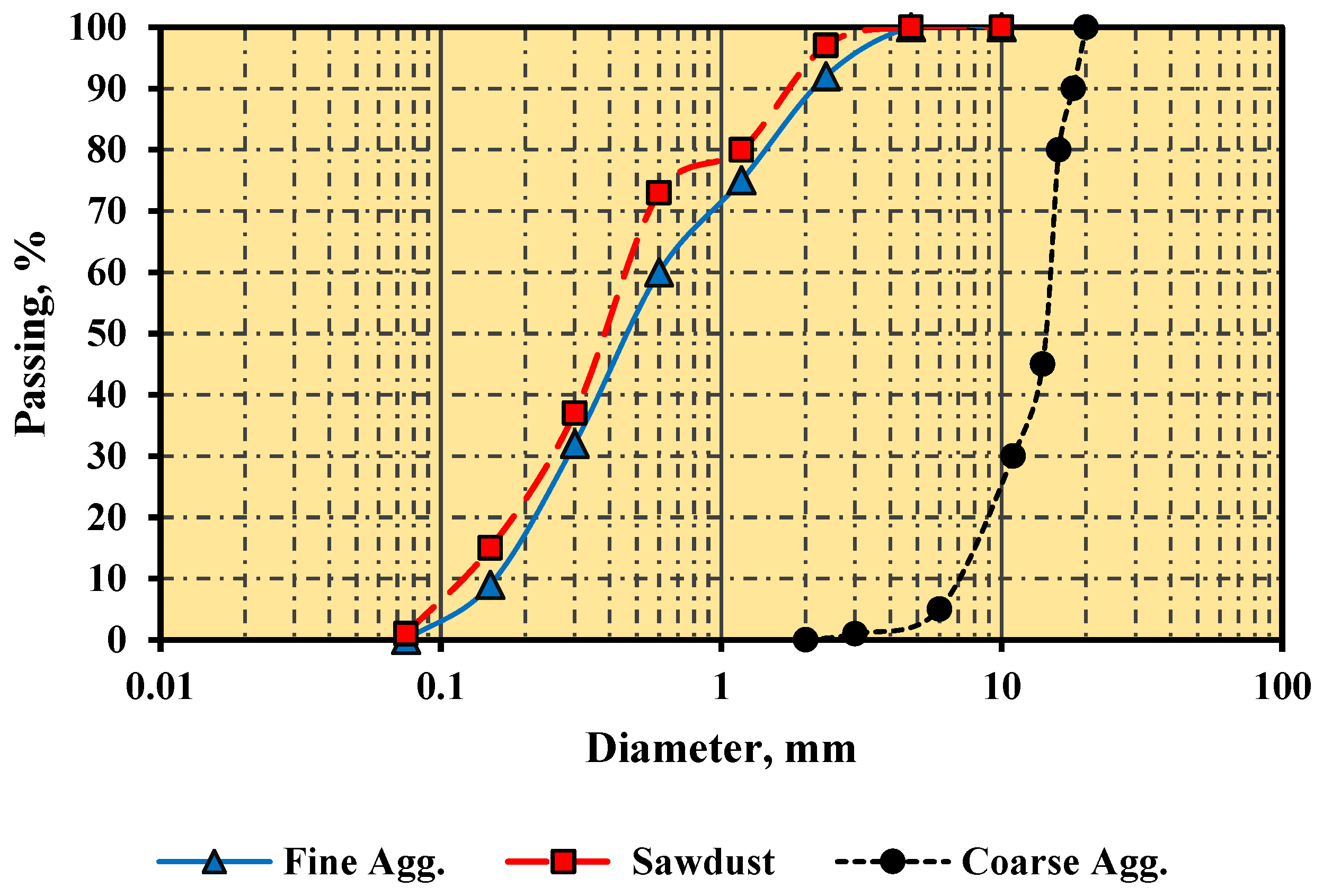
3.1. Material Properties
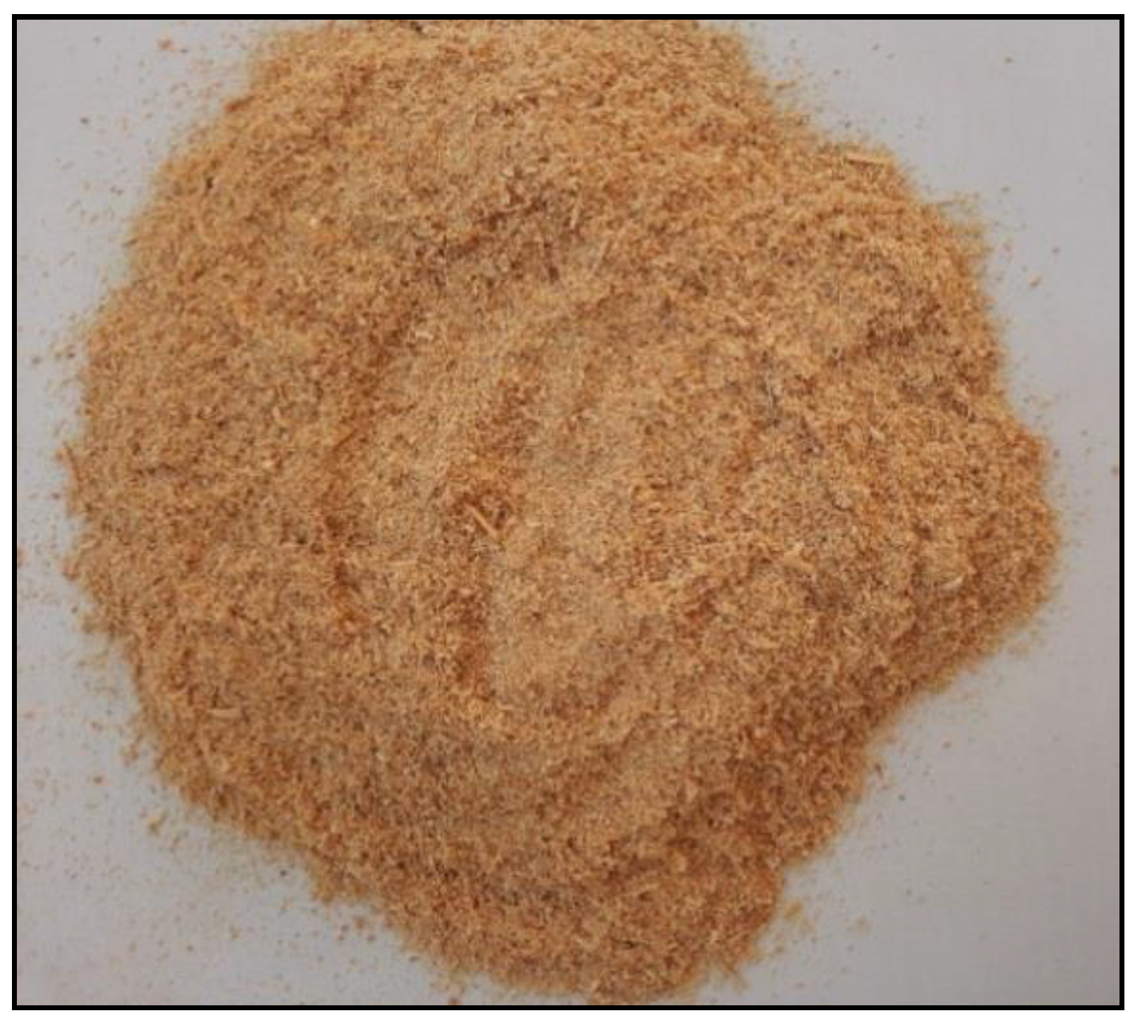
3.1.1. Sawdust
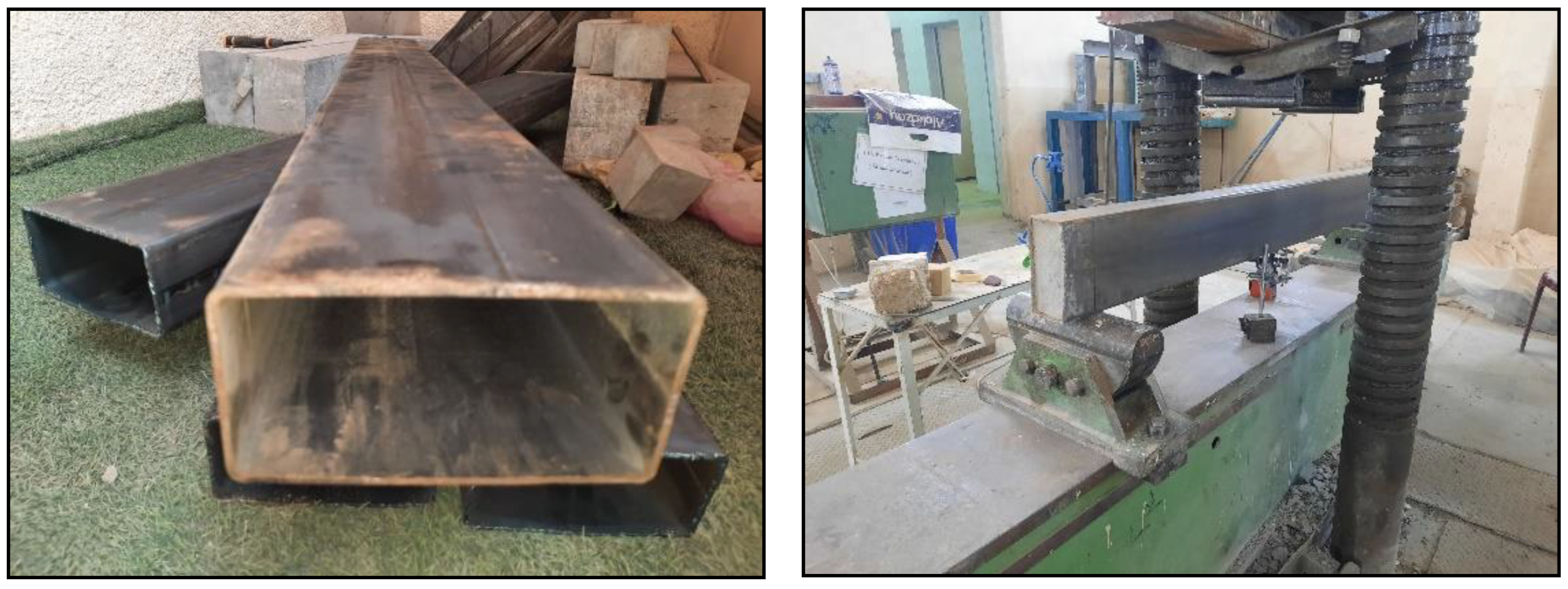
3.1.2. Steel Tubes
3.2. Concrete Mixtures
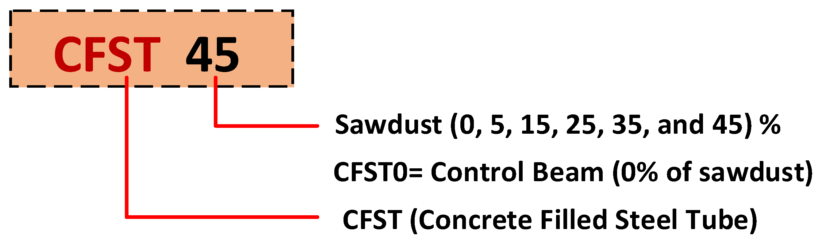
Preparation of the Specimens
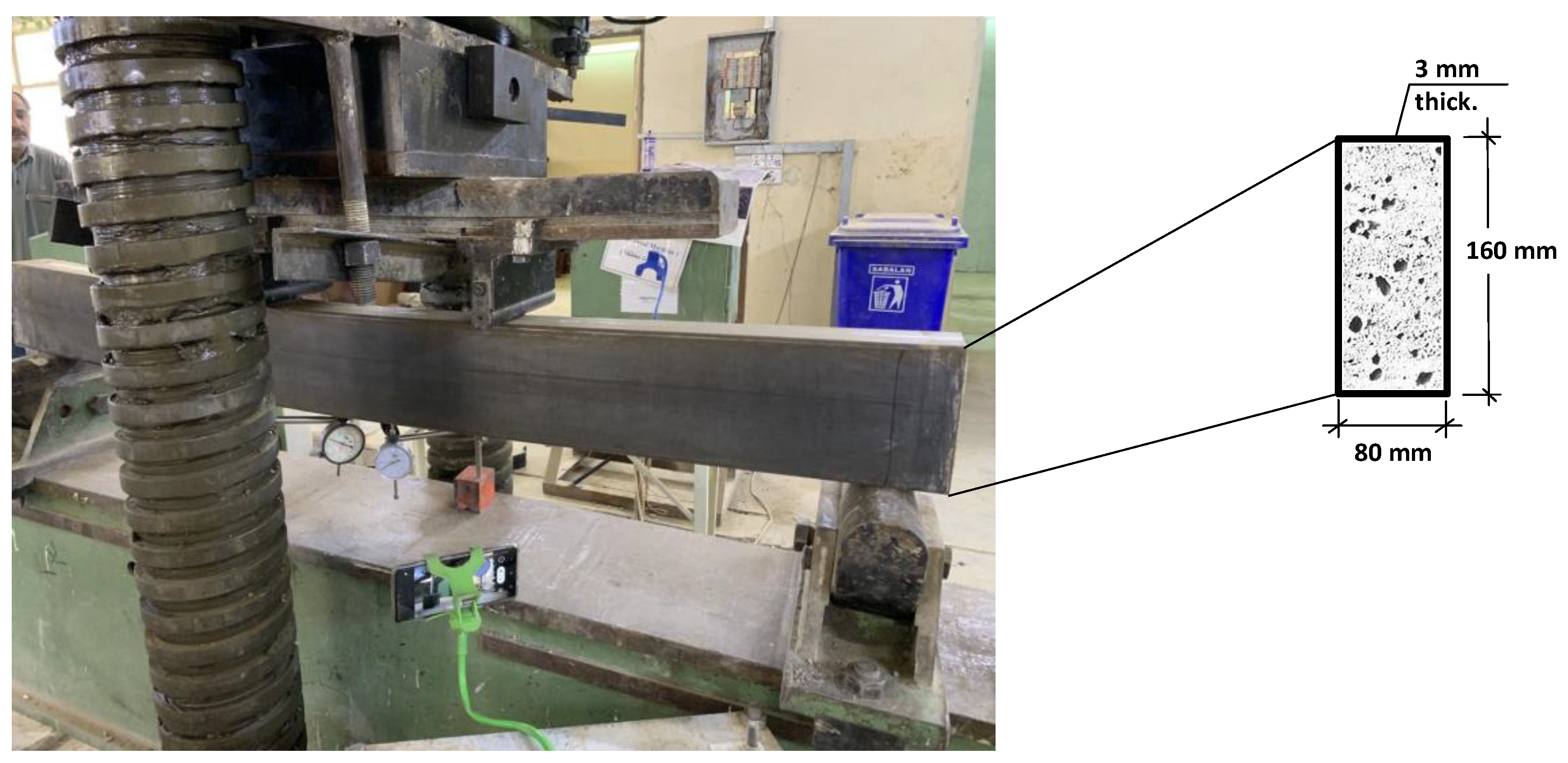
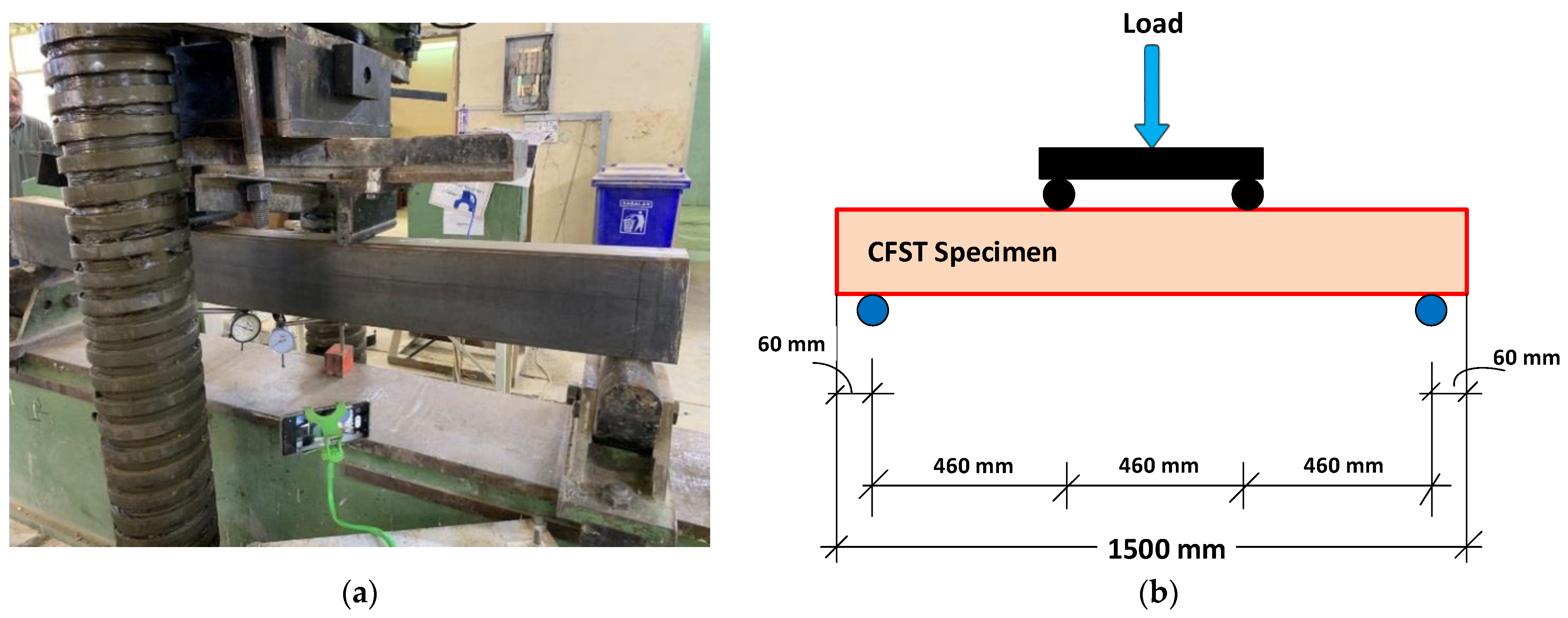
3.3. Instrumentation and Test Setup
4. Analysis and Discussions
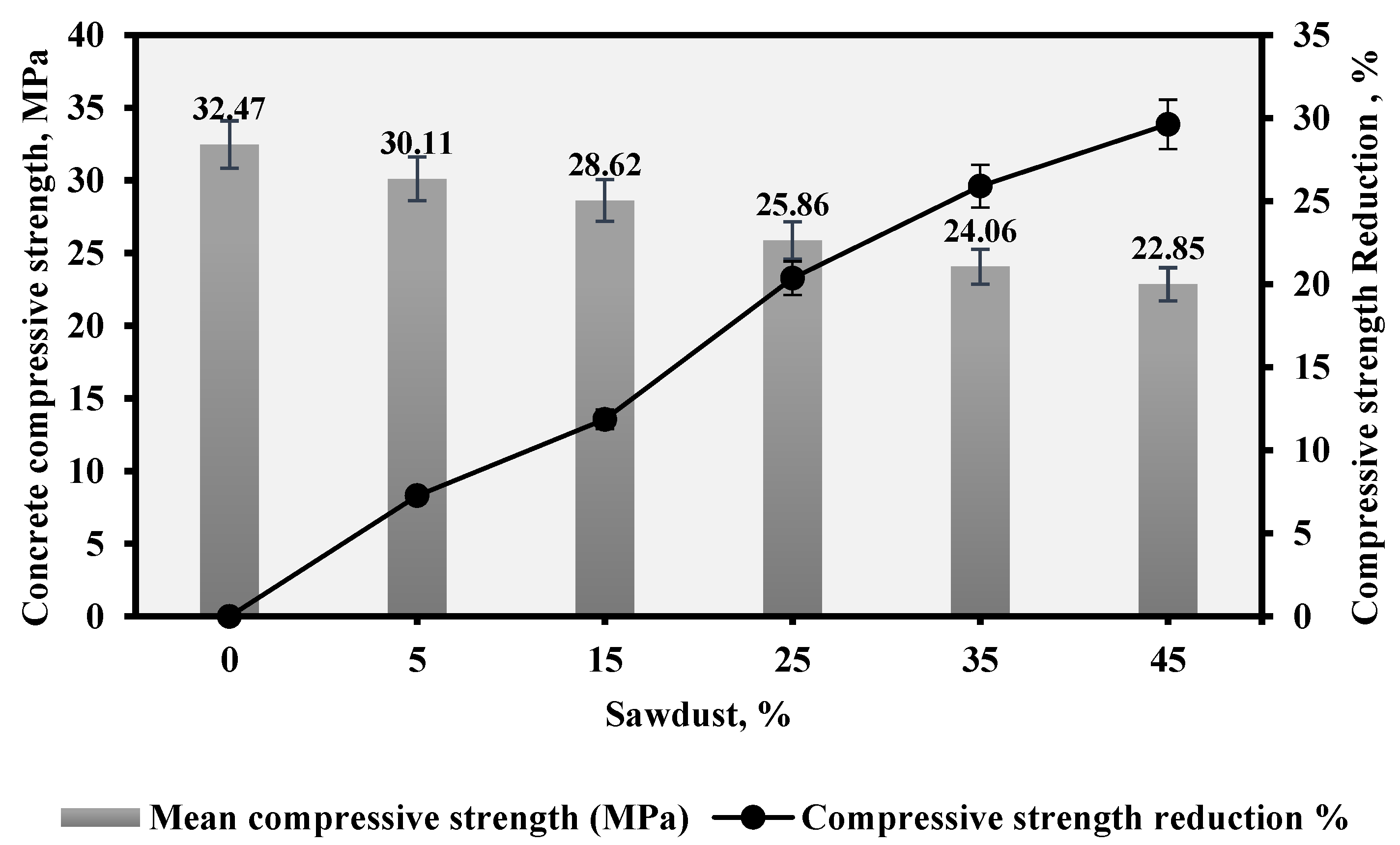
4.1. Compressive Strength
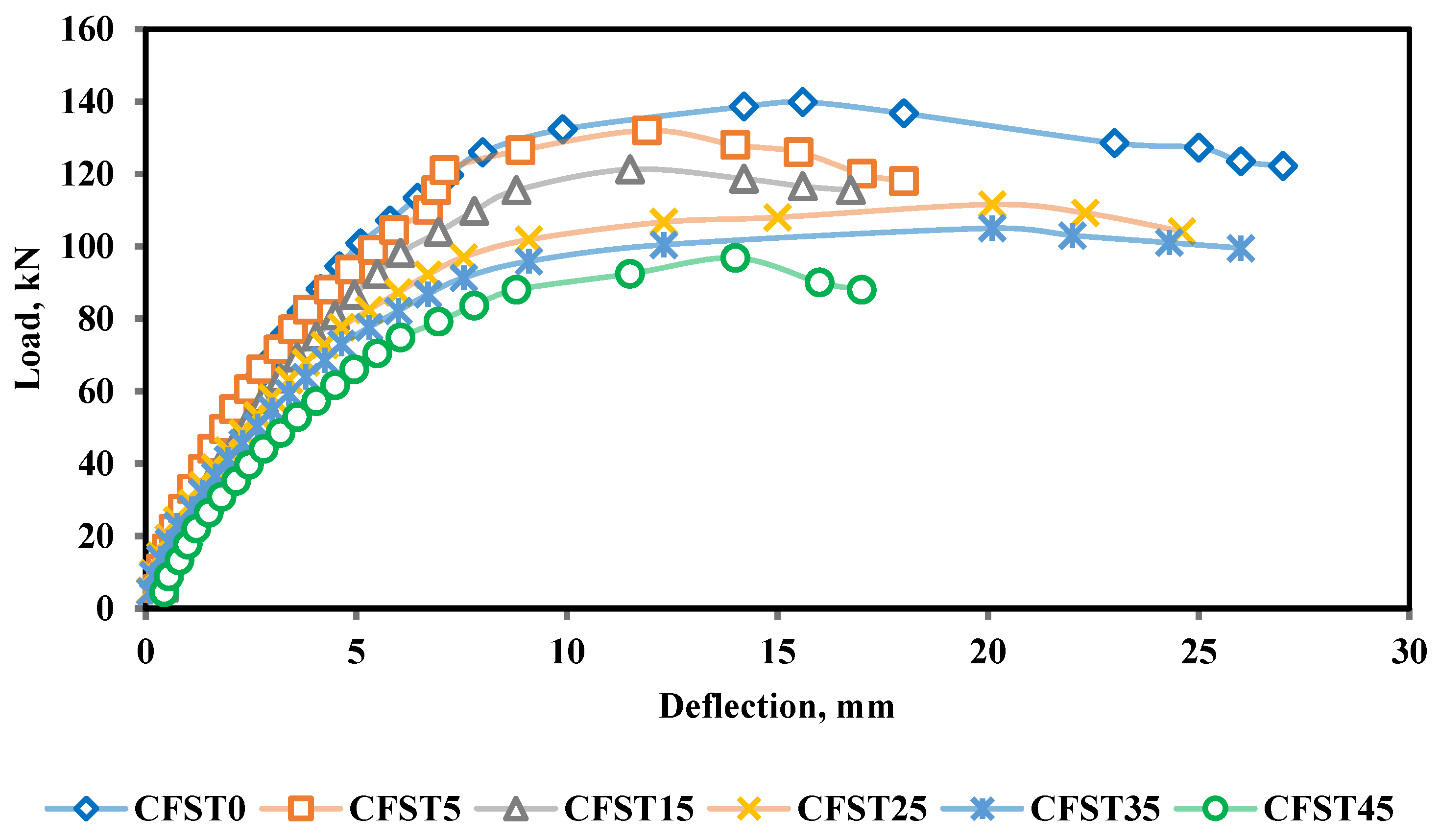
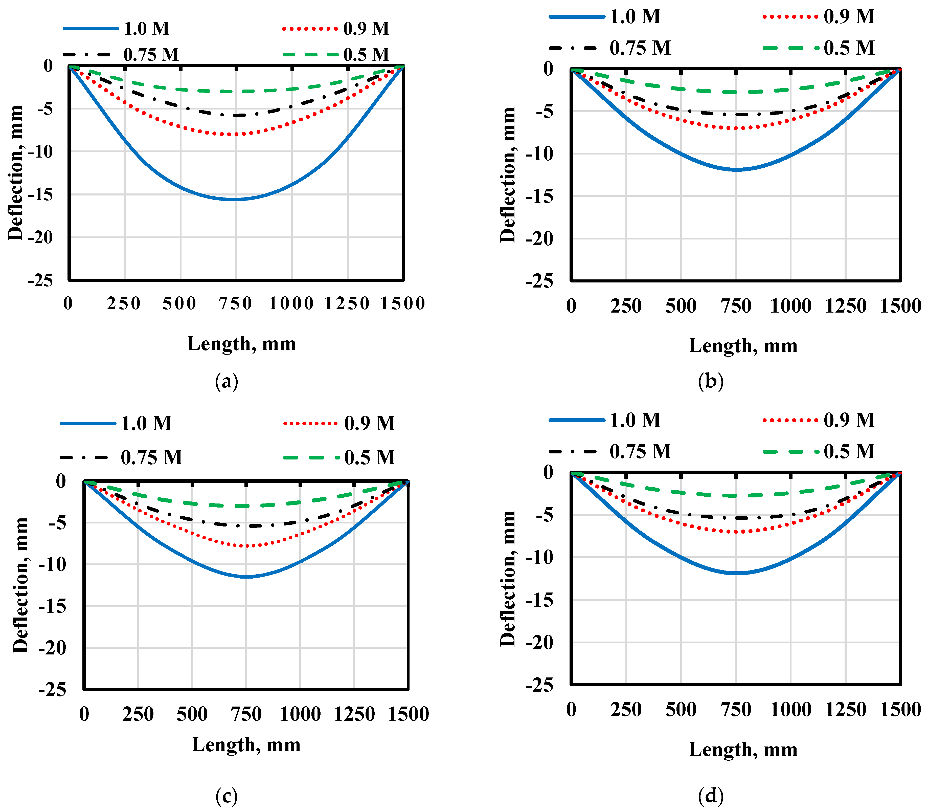
4.2. Load–Deflection Profiles
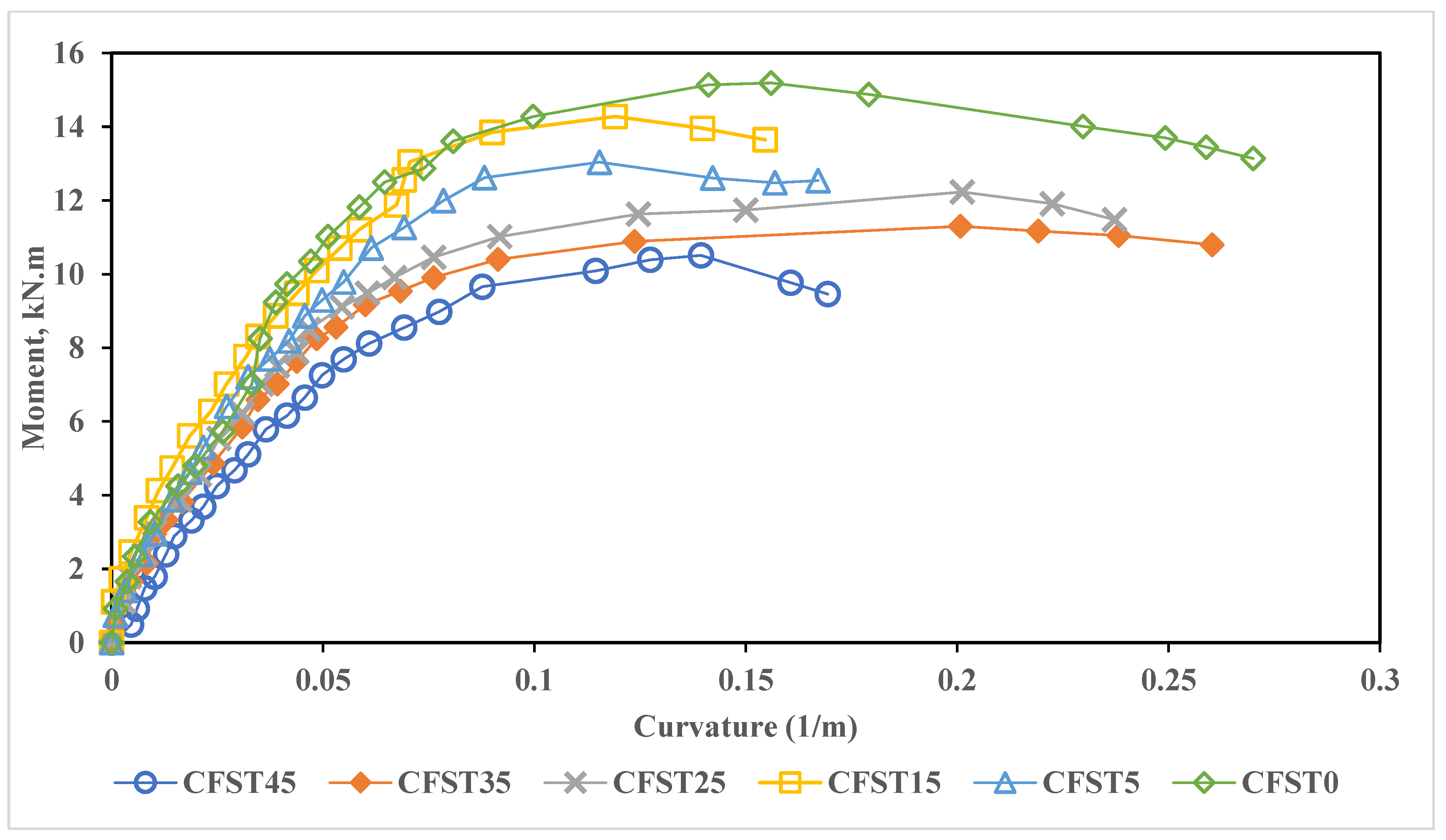
4.3. Moment Capacity
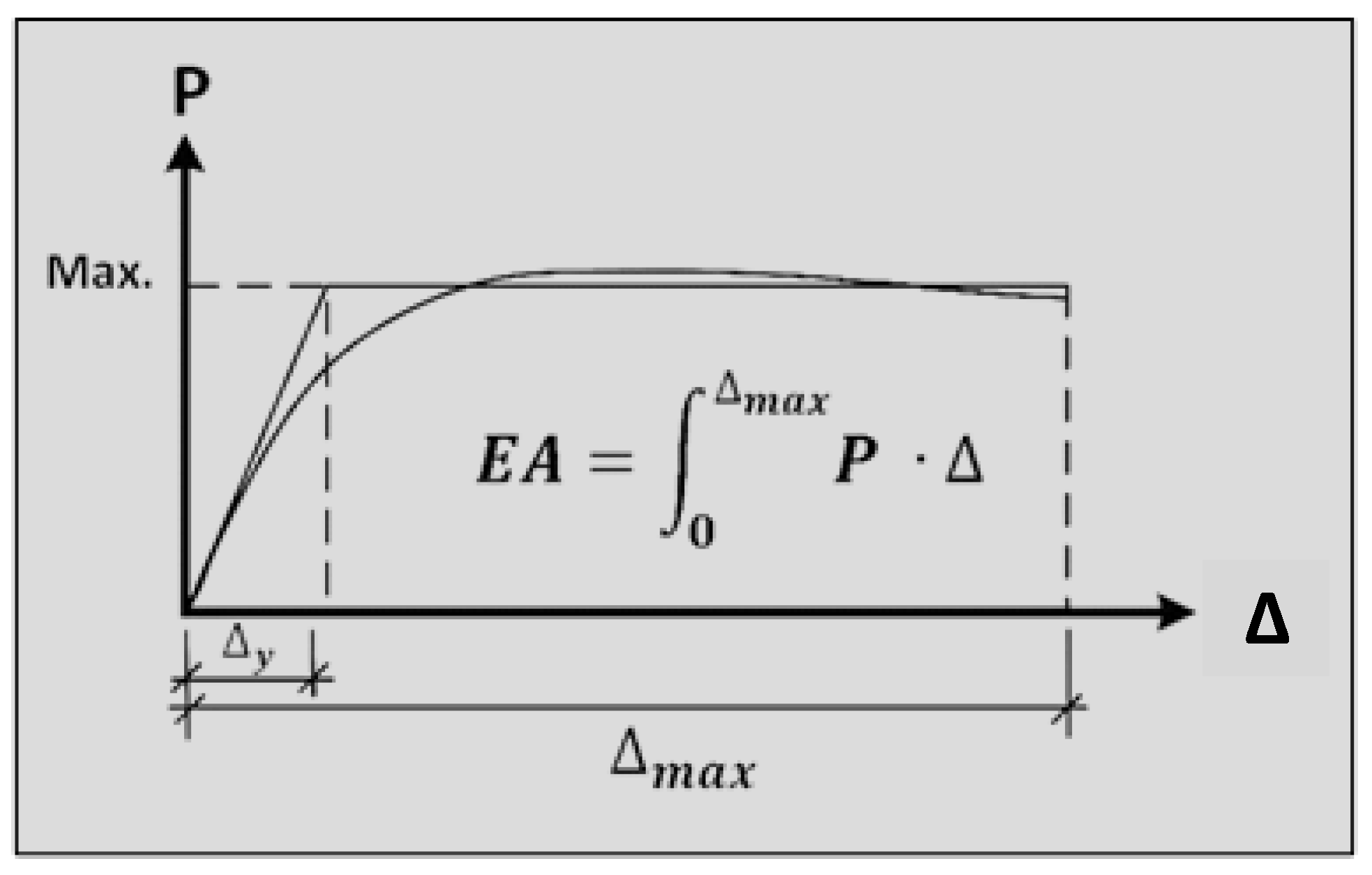
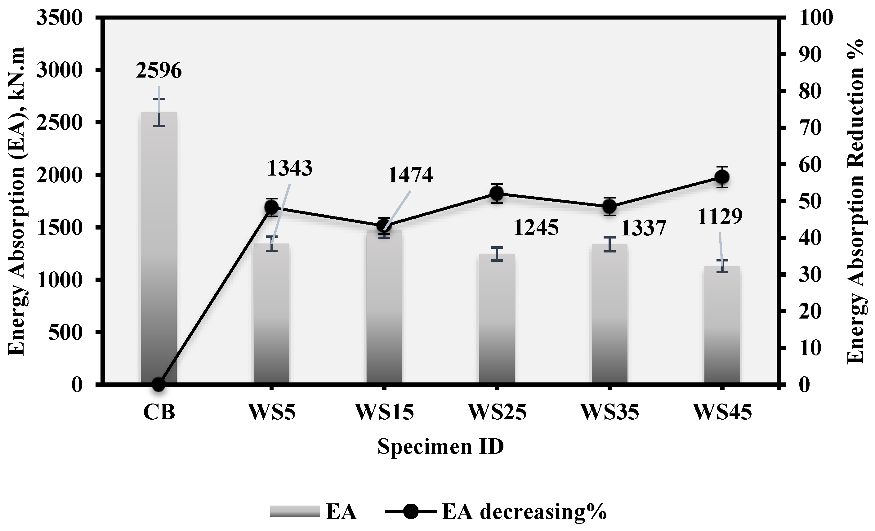
4.4. Energy Absorption
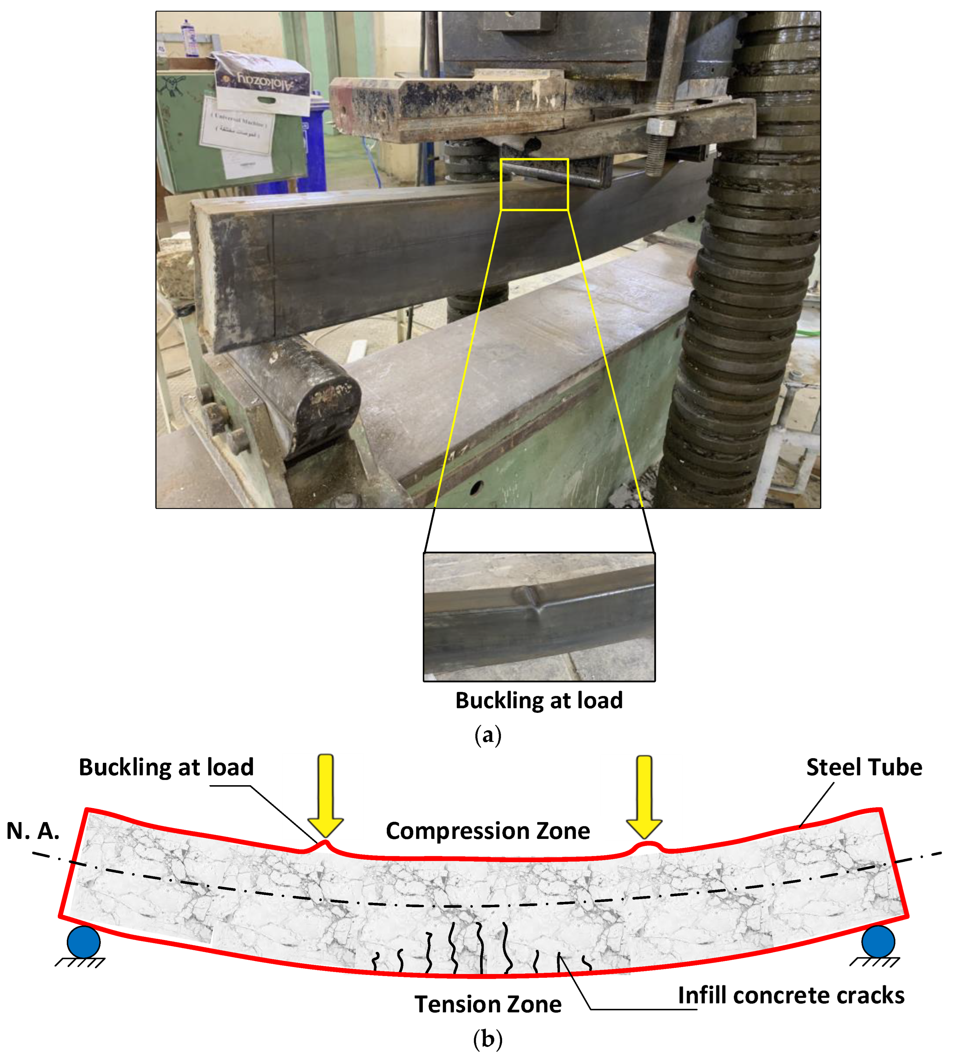
4.5. Failure Modes
5. Numerical Method
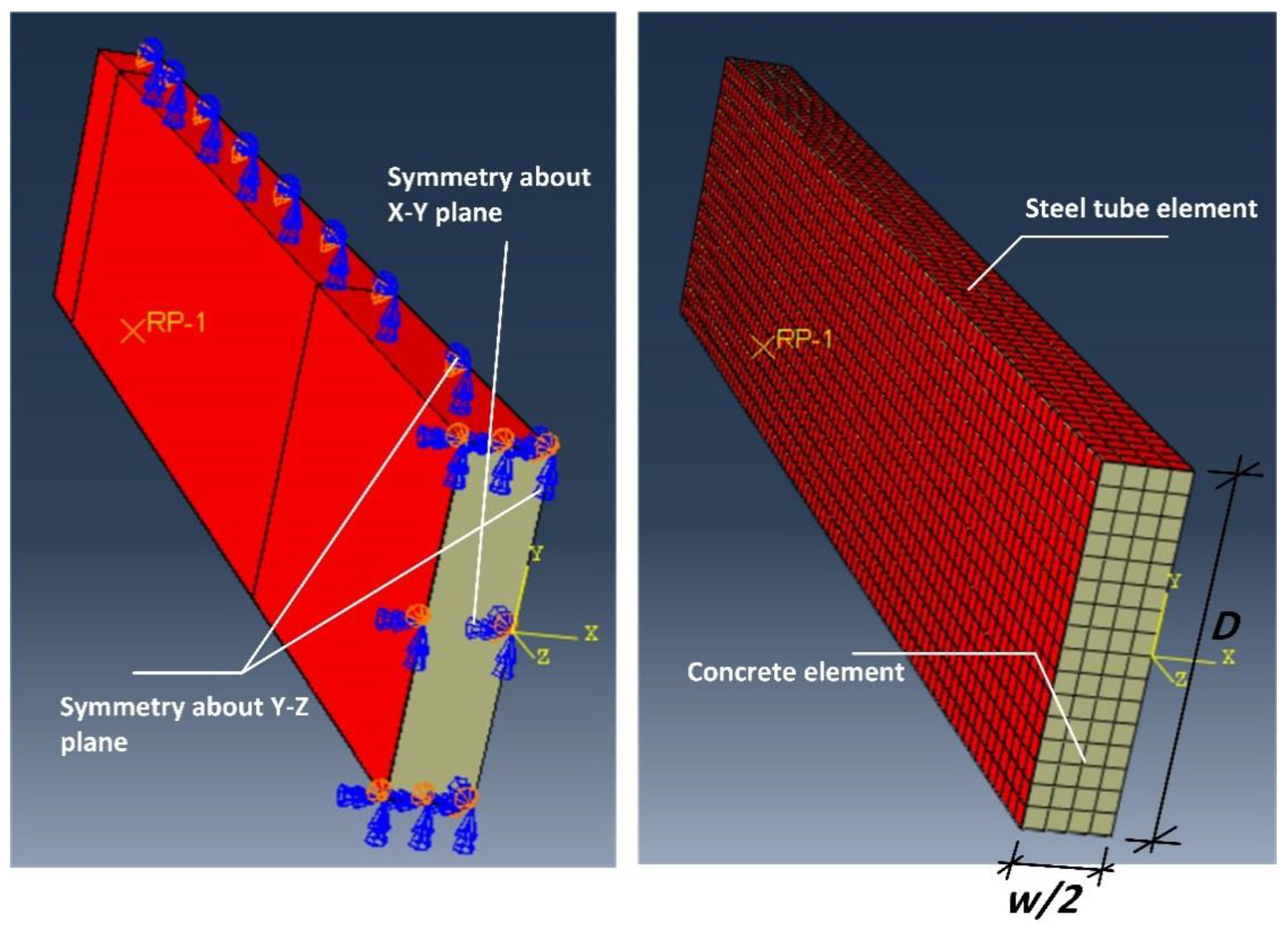
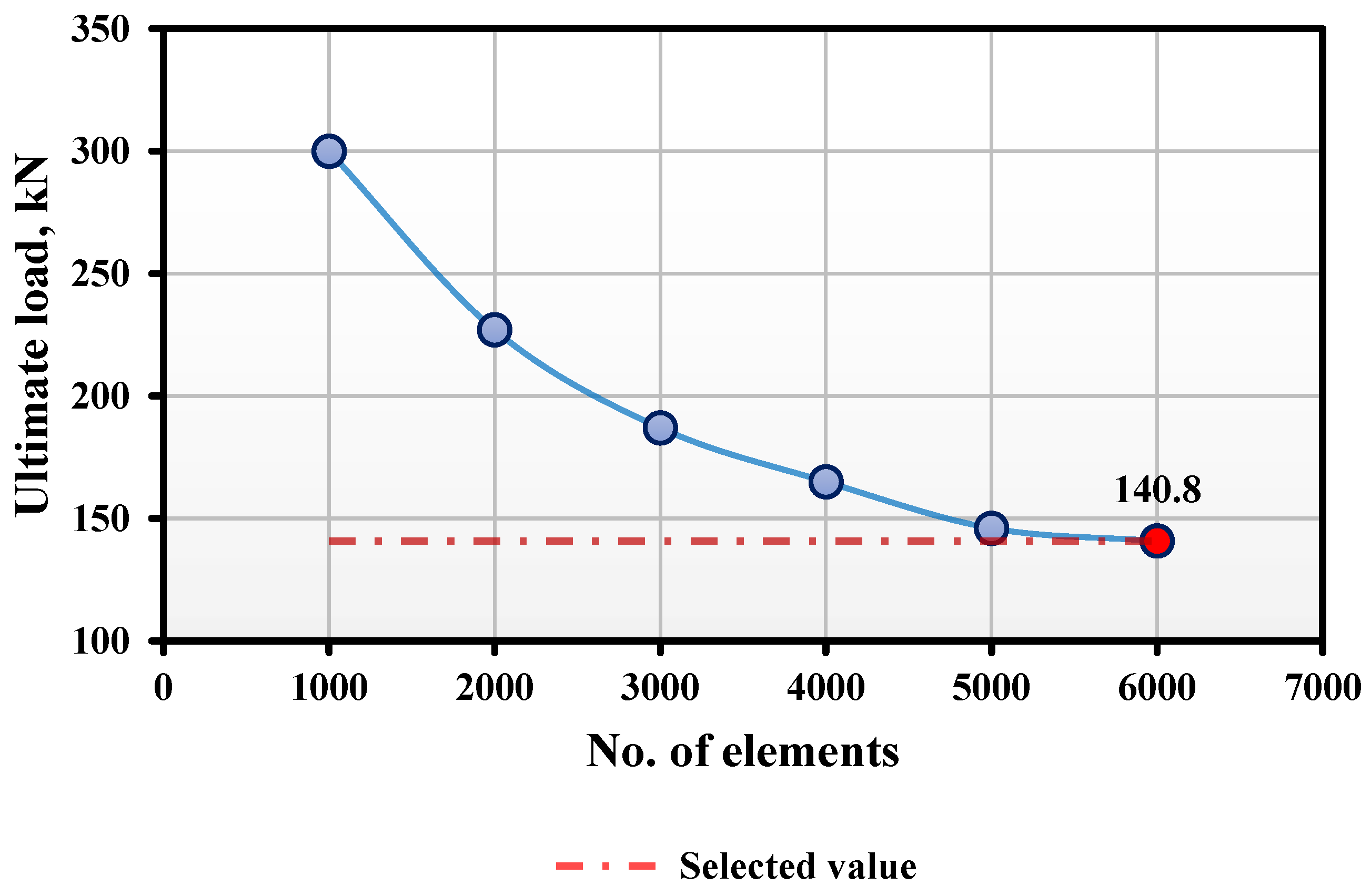
5.1. Finite Element (FE) Modeling
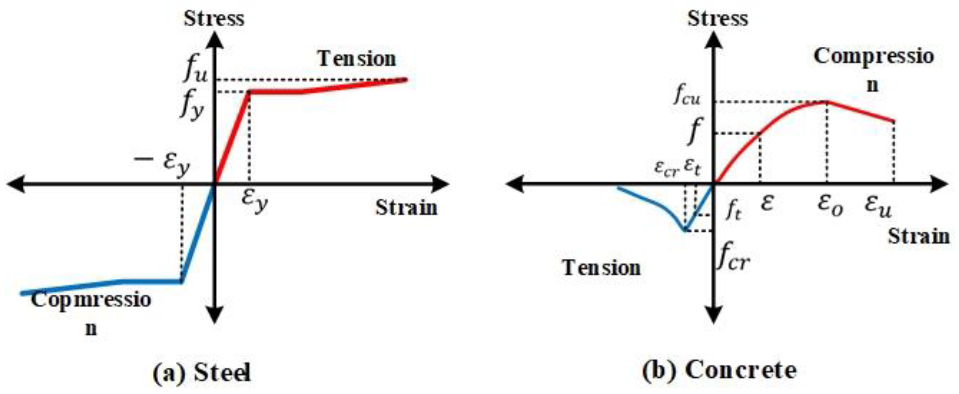
5.2. Constitutive Models of CFST Components
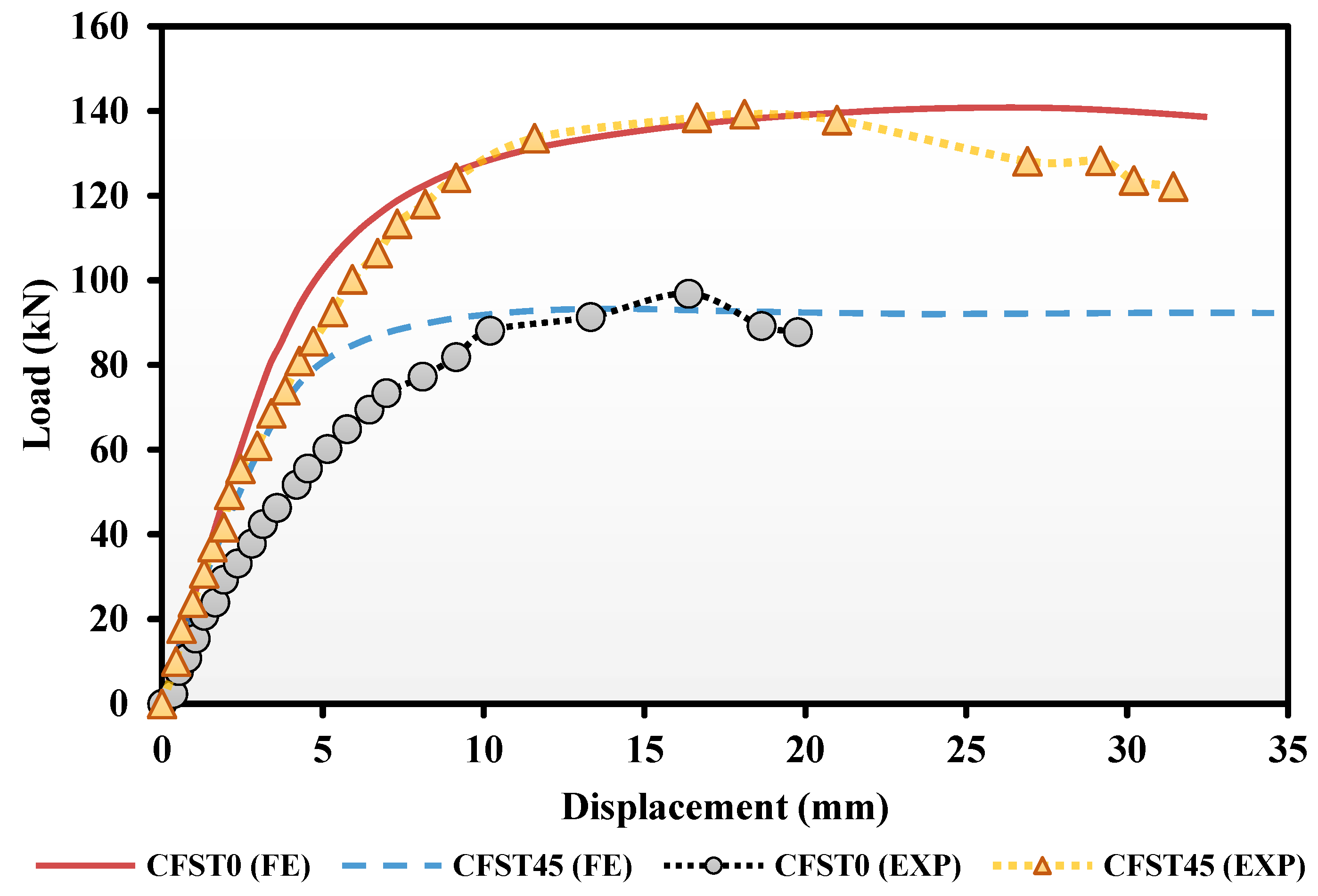
5.3. FE Model Validation
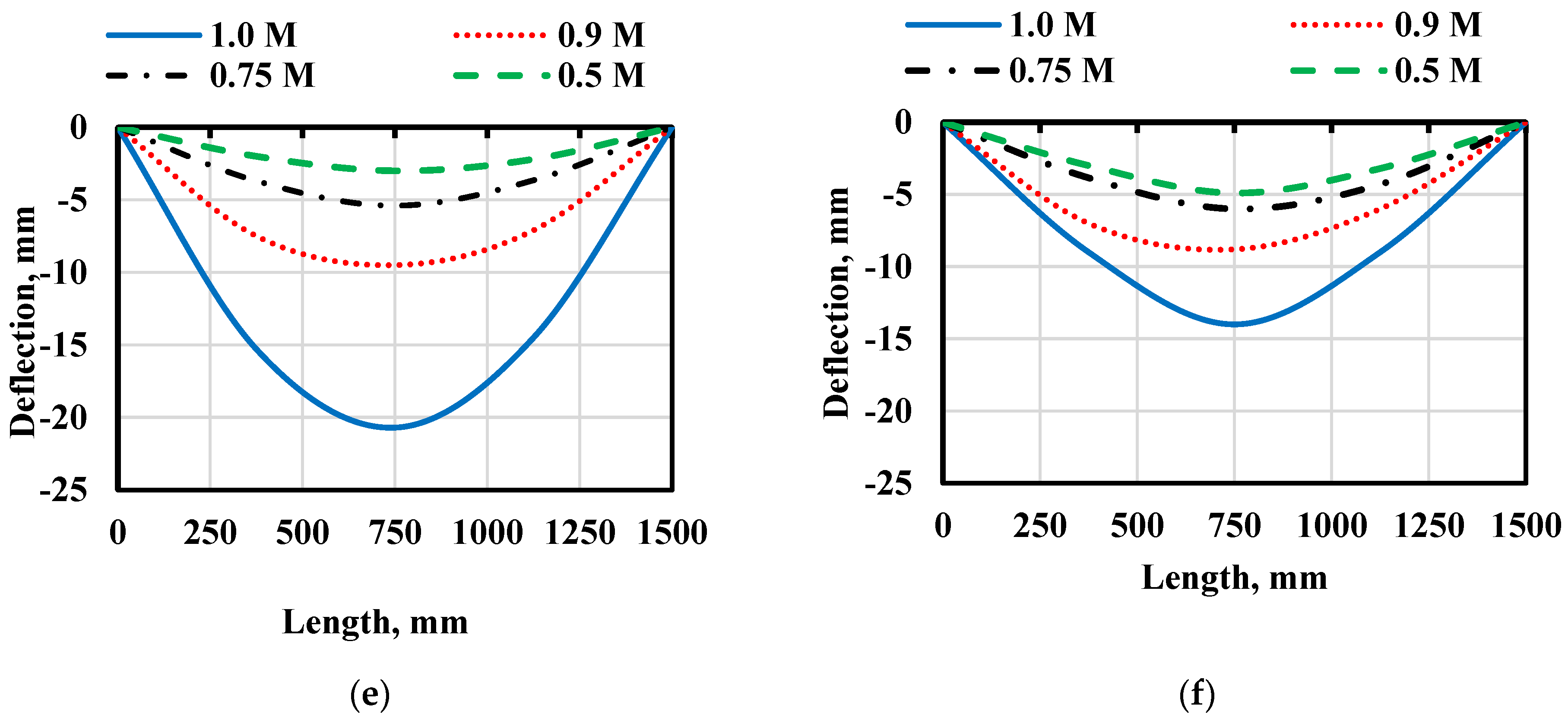
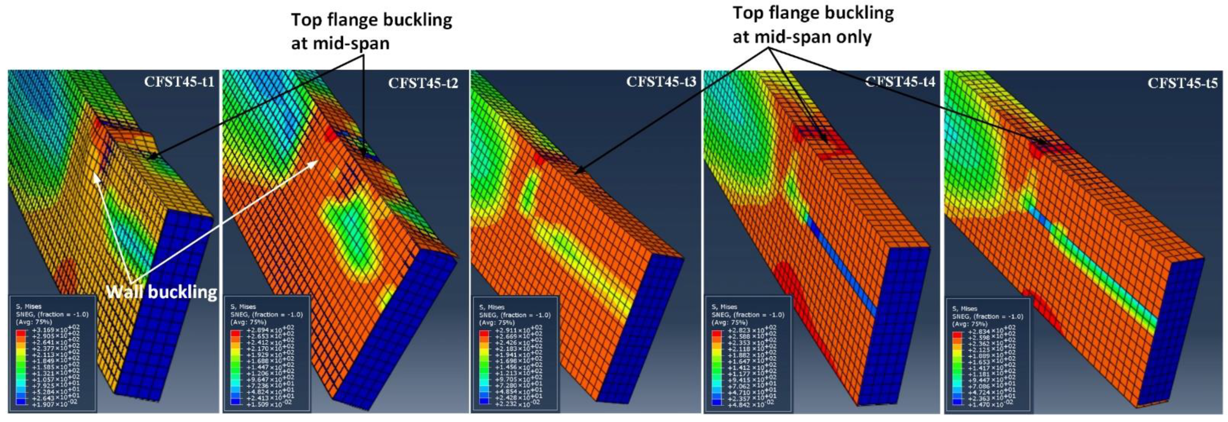
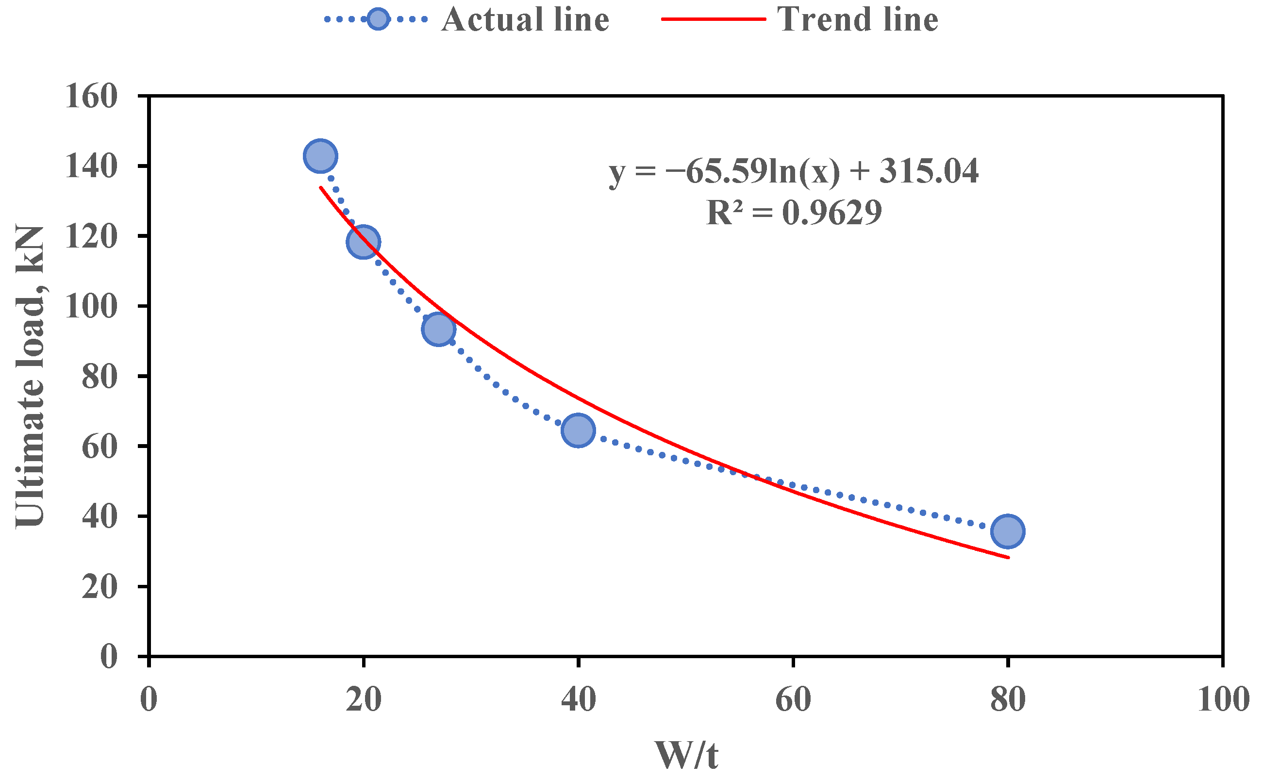
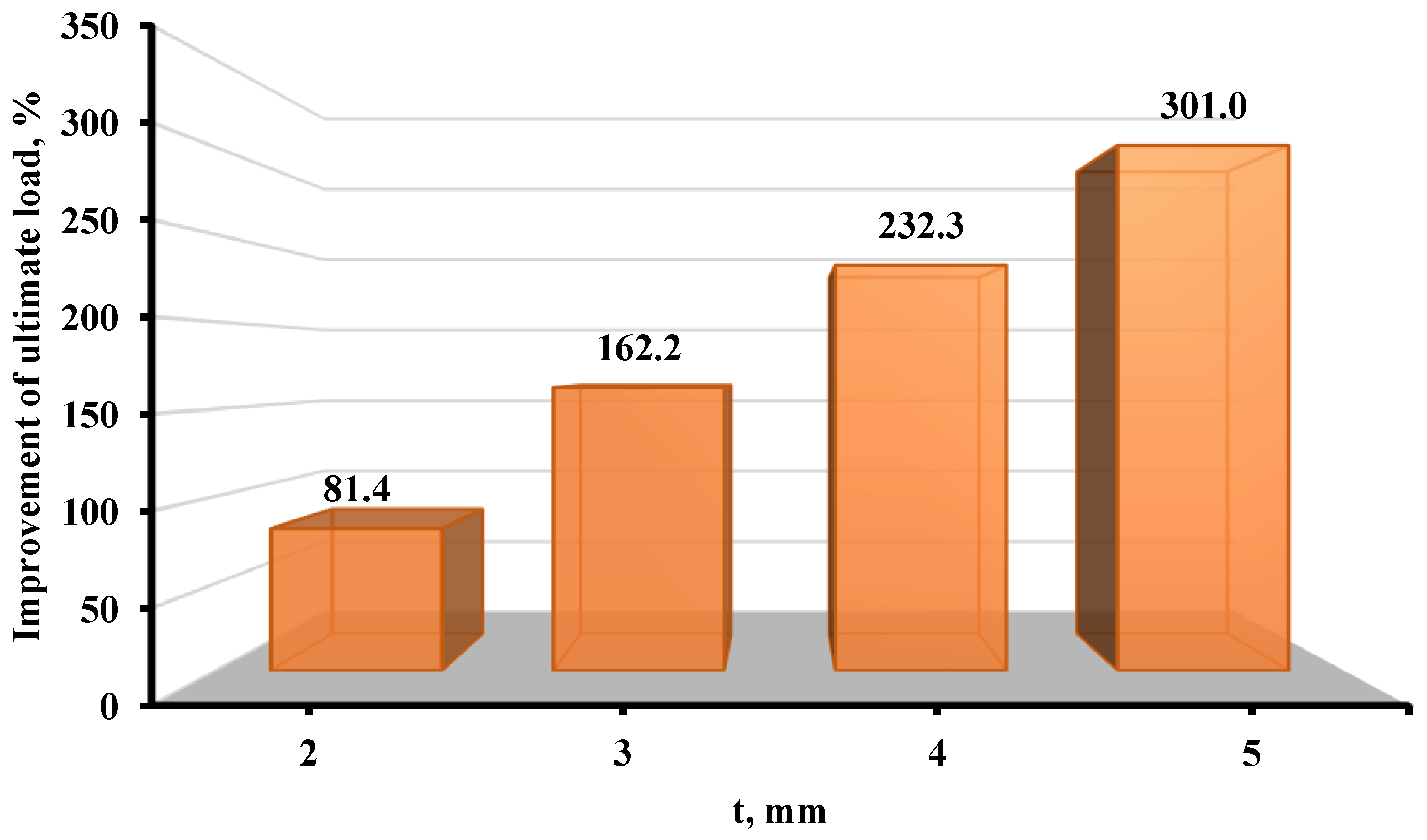
5.4. Impacts of Various Steel Tube Thicknesses
6. Conclusions
- -
- The CFST0 and CFST5 specimens showed typical flexural stiffness characteristics. This was most likely due to the fact that a little amount of sawdust (5%) had no effect on how well the CFST beams performed.
- -
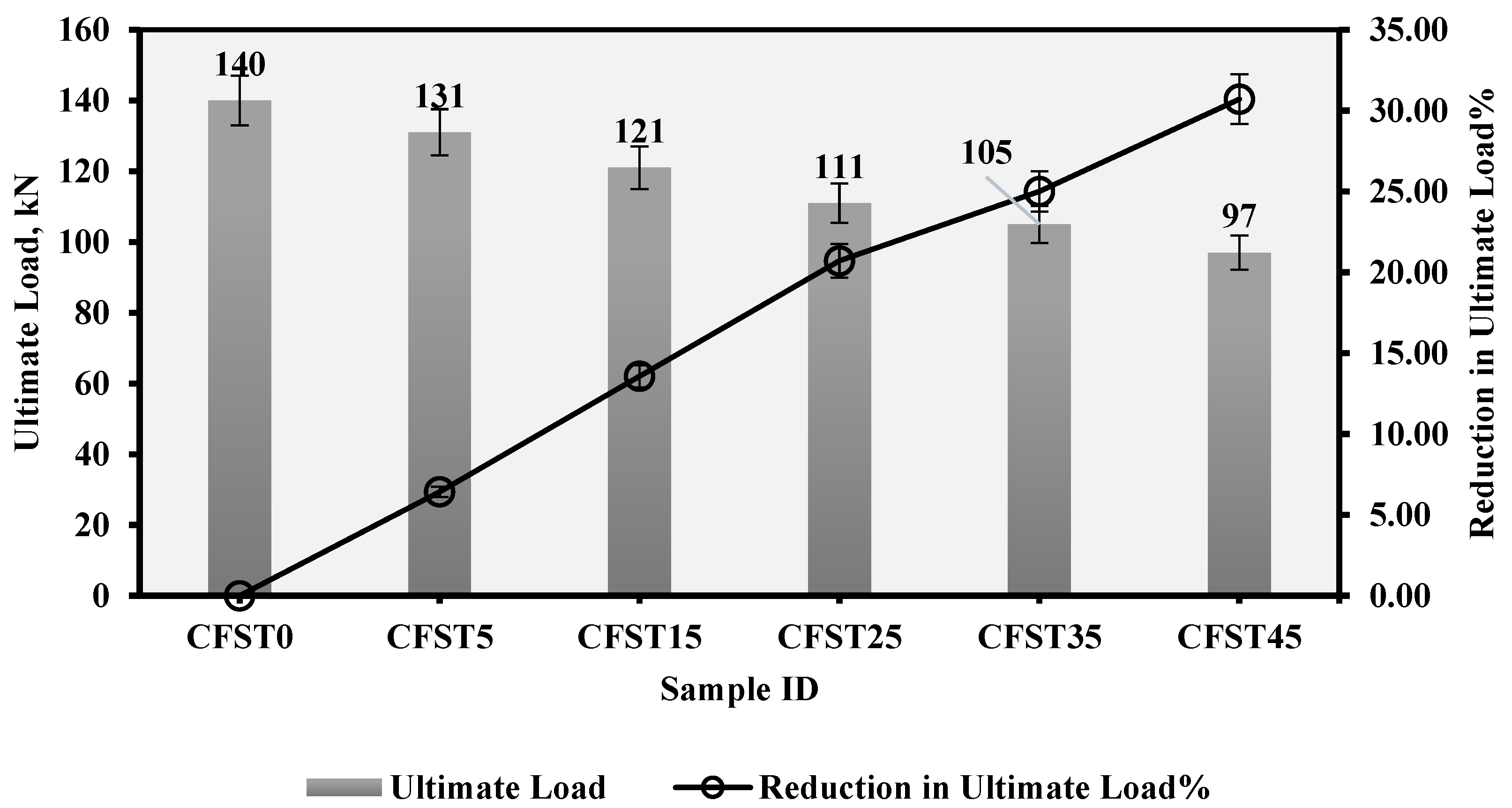
- The test findings for each sample under consideration revealed that the ultimate strength of the samples containing sawdust mixed with concrete was reduced compared to that of the control specimen.
- -
- The maximum load capacity of the evaluated samples fell by a value from 6.43% to 30.71% for sawdust contents ranging from 5% to 45%, as obtained from the experimental testing.
- -
- As the sawdust proportion increased, the compressive strength of the tested samples fell between 7.27% and 29.63%.
- -
- Due to their lowered concrete strength capacity, the evaluated samples containing sawdust had a loading performance comparable to that of the standard concrete specimen, but with lower moment values.
- -
- It is found that when lightweight concrete containing 5% sawdust was utilized, the moment value of the sample CFST0, which was 15.23 kN.m, was lowered by 6.4% (to 14.37 kN.m).
- -
- It was shown that the newly constructed CFST specimens’ flexural behavior was roughly equivalent to that of the conventional (with normal concrete as a filler) CFST samples.
- -
- The sample CFST0 had a greater EA capability as compared to all the push-out-tested beam specimens.
- -
- The samples with added sawdust exhibited a low level of improvement ratio of (43.22–56.52%) compared to the CFST0, due to the increased impact strength, which presented itself as a large area below the load–deflection curve.
- -
- The developed and analyzed CFST model somewhat exceeded the bending capacity of the matching experimented specimens, which confirmed the validity of the recommended FE model.
- -
- When the steel tube thickness of the CFST models rose from 2.0 mm to 5 mm, respective improvements in their ultimate capacity values of approximately 81.4% and 301% were observed.
- -
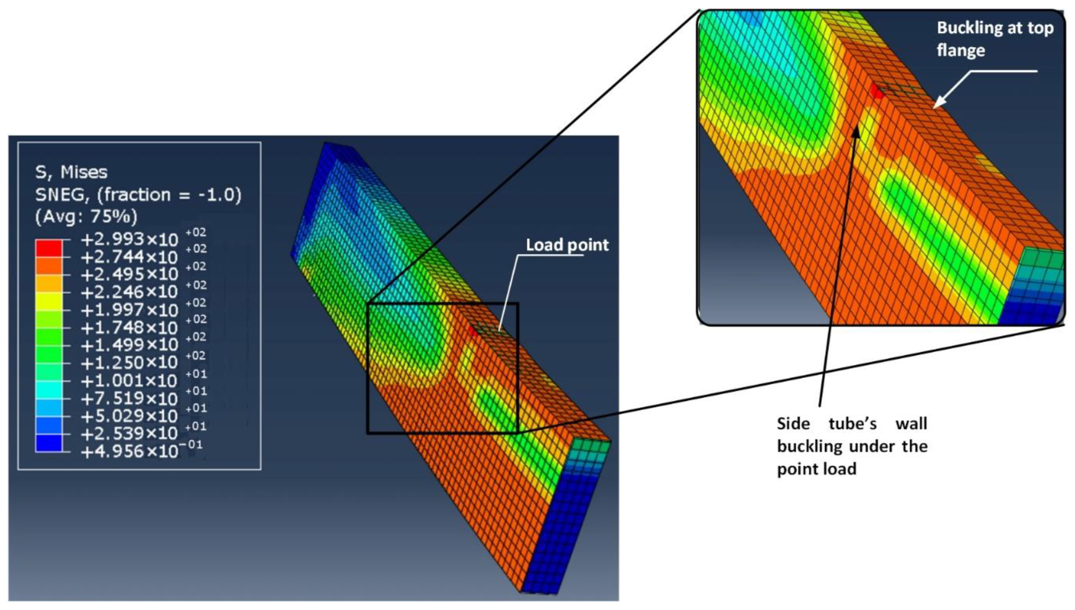
- The created finite element CFST models, including the flexural performance and failure modes, produced findings that were very similar to those of the experimentally tested specimens. As a result, they can be seen as a foundation for additional numerical research on the properties of the proposed CFST.
Author Contributions
Funding
Data Availability Statement
Acknowledgments
Conflicts of Interest
References
- Sharba, A.A.K.; Hason, M.M.; Hanoon, A.N.; Qader, D.N.; Amran, M.; Abdulhameed, A.A.; Al Zand, A.W. Push-out test of waste sawdust-based steel-concrete—Steel composite sections: Experimental and environmental study. Case Stud. Constr. Mater. 2022, 17, e01570. [Google Scholar] [CrossRef]
- Abbas, Z.K. Properties of Roller-Compacted Concrete Pavement Containing Different Waste Material Fillers. J. Eng. 2022, 28, 86–106. [Google Scholar] [CrossRef]
- Mohaisen, S.K.; Abdulhameed, A.A.; Kharnoob, M.M. Behavior of reinforced concrete continuous beams under pure torsion. J. Eng. 2016, 22, 1–15. [Google Scholar] [CrossRef]
- Ji, J.; Zeng, W.; Jiang, L.; Bai, W.; Ren, H.; Chai, Q.; Zhang, L.; Wang, H.; Li, Y.; He, L. Hysteretic Behavior on Asymmetrical Composite Joints with Concrete-Filled Steel Tube Columns and Unequal High Steel Beams. Symmetry 2021, 13, 2381. [Google Scholar] [CrossRef]
- Le, K.B.; Cao, V.V. Numerical Study of Circular Concrete Filled Steel Tubes Subjected to Pure Torsion. Buildings 2021, 11, 397. [Google Scholar] [CrossRef]
- Salih, S.A.; Kzar, A.M. Studying the Utility of Using Reed and Sawdust as Waste Materials to Produce Cementitious Building Units. J. Eng. 2015, 21, 36–54. [Google Scholar]
- Mahmod, H.M.; Aznieta, A.A.F.N.; Gatea, S.J. Evaluation of rubberized fibre mortar exposed to elevated temperature using destructive and non-destructive testing. KSCE J. Civ. Eng. 2017, 21, 1347–1358. [Google Scholar] [CrossRef]
- Ahmed, A.A.; Masmoudi, R. Axial Response of Concrete-Filled FRP Tube (CFFT) Columns with Internal Bars. J. Compos. Sci. 2018, 2, 57. [Google Scholar] [CrossRef] [Green Version]
- Alshimmeri, A.J.H. Structural Behavior of Confined Concrete Filled Aluminum Tubular (CFT) Columns under Concentric Load. J. Eng. 2016, 22, 125–139. [Google Scholar]
- Saatcioglu, M.; Razvi, S.R. Strength and ductility of confined concrete. J. Struct. Eng. 1992, 118, 1590–1607. [Google Scholar] [CrossRef]
- Xiao, Y.; He, W.; Choi, K.-K. Confined Concrete-Filled Tubular Columns. J. Struct. Eng. 2005, 131, 488–497. [Google Scholar] [CrossRef] [Green Version]
- Konno, K.; Sato, Y.; Kakuta, Y.; Ohira, M. The property of recycled concrete column encased by steel tube subjected to axial compression. Trans. Jpn. Concr. Inst. 1998, 19, 231–238. [Google Scholar]
- Yang, Y.-F.; Ma, G.-L. Experimental behaviour of recycled aggregate concrete filled stainless steel tube stub columns and beams. Thin-Walled Struct. 2013, 66, 62–75. [Google Scholar] [CrossRef]
- Bambach, M.R. Axial capacity and crushing behavior of metal–fiber square tubes—Steel, stainless steel and aluminum with CFRP. Compos. Part B Eng. 2010, 41, 550–559. [Google Scholar] [CrossRef]
- Batool, F.; Islam, K.; Cakiroglu, C.; Shahriar, A. Effectiveness of wood waste sawdust to produce medium- to low-strength concrete materials. J. Build. Eng. 2021, 44, 103237. [Google Scholar] [CrossRef]
- Kirilenko, A.P.; Sedjo, R.A. Climate change impacts on forestry. Proc. Natl. Acad. Sci. USA 2007, 104, 19697–19702. [Google Scholar] [CrossRef] [Green Version]
- Jannat, N.; Al-Mufti, R.L.; Hussien, A.; Abdullah, B.; Cotgrave, A. Influence of Sawdust Particle Sizes on the Physico-Mechanical Properties of Unfired Clay Blocks. Designs 2021, 5, 57. [Google Scholar] [CrossRef]
- Ahmed, W.; Khushnood, R.A.; Memon, S.A.; Ahmad, S.; Baloch, W.L.; Usman, M. Effective use of sawdust for the production of eco-friendly and thermal-energy efficient normal weight and lightweight concretes with tailored fracture properties. J. Clean. Prod. 2018, 184, 1016–1027. [Google Scholar] [CrossRef]
- Bratkovich, S.; Howe, J.; Bowyer, J.; Pepke, E.; Frank, M.; Fernholz, K. Municipal solid waste (Msw) and construction and demolition (C&D) wood waste generation and recovery in the United States. Dovetail Partn. Minneap. 2014, 1, 1–16. [Google Scholar] [CrossRef] [Green Version]
- Alabduljabbar, H.; Huseien, G.F.; Sam, A.R.; Alyouef, R.; Algaifi, H.A.; Alaskar, A. Engineering Properties of Waste Sawdust-Based Lightweight Alkali-Activated Concrete: Experimental Assessment and Numerical Prediction. Materials 2020, 13, 5490. [Google Scholar] [CrossRef]
- Adebakin, I.H.; Adeyemi, A.A.; Adu, J.T.; Ajayi, F.A.; Lawal, A.A.; Ogunrinola, O.B. Uses of sawdust as admixture in production of low-cost and lightweight hollow sandcrete blocks. Am. J. Sci. Ind. Res. 2012, 3, 458–463. [Google Scholar]
- Udoeyo, F.F.; Dashibil, P.U. Sawdust Ash as Concrete Material. J. Mater. Civ. Eng. 2002, 14, 173–176. [Google Scholar] [CrossRef]
- Sosoi, G.; Abid, C.; Barbuta, M.; Burlacu, A.; Balan, M.C.; Branoaea, M.; Vizitiu, R.S.; Rigollet, F. Experimental Investigation on Mechanical and Thermal Properties of Concrete Using Waste Materials as an Aggregate Substitution. Materials 2022, 15, 1728. [Google Scholar] [CrossRef] [PubMed]
- Oyedepo, O.J.; Oluwajana, S.D.; Akande, S.P. Investigation of properties of concrete using sawdust as partial replacement for sand. Civ. Environ. Res. 2014, 6, 35–42. [Google Scholar]
- Boob, T.N. Performance of saw-dust in low cost sandcrete blocks. Am. J. Eng. Res. 2014, 3, 197–206. [Google Scholar]
- Mageswari, M.; Vidivelli, B. The use of sawdust ash as fine aggregate replacement in concrete. J. Environ. Res. Dev. 2009, 3, 720–726. [Google Scholar]
- ASTM A500/A500M-13; Standard Specification for Cold-Formed Welded and Seamless Carbon Steel Structural Tubing in Rounds and Shapes. ASTM: West Conshohocken, PA, USA, 2013.
- ASTM-C39/C39M; Standard Test Method for Compressive Strength of Cylindrical Concrete Specimens. ASTM American Society for Testing and Materials: West Conshohocken, PA, USA, 2016; p. 7. [CrossRef]
- Hason, M.M.; Mussa, M.H.; Abdulhadi, A.M. Flexural ductility performance of hybrid-recycled aggregate reinforced concrete T-beam. Mater. Today Proc. 2021, 46, 682–688. [Google Scholar] [CrossRef]
- Odaa, S.A.; Hason, M.M.; Sharba, A.A.K. Self-compacting concrete beams reinforced with steel fiber under flexural loads: A ductility index evaluation. Mater. Today Proc. 2021, 42, 2259–2267. [Google Scholar] [CrossRef]
- Godat, A.; Qu, Z.; Lu, X.Z.; Labossière, P.; Ye, L.P.; Neale, K.W. Size Effects for Reinforced Concrete Beams Strengthened in Shear with CFRP Strips. J. Compos. Constr. 2010, 14, 260–271. [Google Scholar] [CrossRef]
- Nielsen, M.; Hoang, L.C. Limit Analysis and Concrete Plasticity; CRC Press: Boca Raton, FL, USA, 2016. [Google Scholar]
- Teng, J.G.; Hu, Y.M. Behaviour of FRP-jacketed circular steel tubes and cylindrical shells under axial compression. Constr. Build. Mater. 2007, 21, 827–838. [Google Scholar] [CrossRef]
- Bambach, M.R.; Jama, H.; Zhao, X.L.; Grzebieta, R.H. Hollow and concrete filled steel hollow sections under transverse impact loads. Eng. Struct. 2008, 30, 2859–2870. [Google Scholar] [CrossRef]
- Al Zand, A.W.; Hosseinpour, E.; Badaruzzaman, W.H.W. The influence of strengthening the hollow steel tube and CFST beams using U-shaped CFRP wrapping scheme. Struct. Eng. Mech. Int. J. 2018, 66, 229–235. [Google Scholar]
- Al Zand, A.W.; Badaruzzaman, W.H.W.; Al-Shaikhli, M.S.; Ali, M.M. Flexural performance of square concrete-filled steel tube beams stiffened with V-shaped grooves. J. Constr. Steel Res. 2020, 166, 105930. [Google Scholar] [CrossRef]
- Yang, Y.-F. Modelling of recycled aggregate concrete-filled steel tube (RACFST) beam-columns subjected to cyclic loading. Steel Compos. Struct. 2015, 18, 213–233. [Google Scholar] [CrossRef]
- Al-Zand, A.W.; Badaruzzaman, W.H.W.; Ali, M.M.; Hasan, Q.A.; Al-Shaikhli, M.S. Flexural performance of cold-formed square CFST beams strengthened with internal stiffeners. Steel Compos. Struct. Int. J. 2020, 34, 123–139. [Google Scholar] [CrossRef]
- Al Zand, A.W.; Badaruzzaman, W.H.W.; Mutalib, A.A.; Hilo, S.J. Flexural behavior of CFST beams partially strengthened with unidirectional CFRP sheets: Experimental and theoretical study. J. Compos. Constr. 2018, 22, 4018018. [Google Scholar] [CrossRef]
- Al Zand, A.W.; Badaruzzaman, W.H.W.; Mutalib, A.A.; Hilo, S.J. Rehabilitation and strengthening of high-strength rectangular CFST beams using a partial wrapping scheme of CFRP sheets: Experimental and numerical study. Thin-Walled Struct. 2017, 114, 80–91. [Google Scholar] [CrossRef]
- Moon, J.; Roeder, C.W.; Lehman, D.E.; Lee, H.-E. Analytical modeling of bending of circular concrete-filled steel tubes. Eng. Struct. 2012, 42, 349–361. [Google Scholar] [CrossRef]
- Javed, M.F.; Sulong, N.H.R.; Memon, S.A.; Rehman, S.K.U.; Khan, N.B. FE modelling of the flexural behaviour of square and rectangular steel tubes filled with normal and high strength concrete. Thin-Walled Struct. 2017, 119, 470–481. [Google Scholar] [CrossRef]
- Feng, R.; Chen, Y.; Wei, J.; Huang, J.; Huang, J.; He, K. Experimental and numerical investigations on flexural behaviour of CFRP reinforced concrete-filled stainless steel CHS tubes. Eng. Struct. 2018, 156, 305–321. [Google Scholar] [CrossRef]
- Wang, J.; Shen, Q.; Wang, F.; Wang, W. Experimental and analytical studies on CFRP strengthened circular thin-walled CFST stub columns under eccentric compression. Thin-Walled Struct. 2018, 127, 102–119. [Google Scholar] [CrossRef]


| Specimen Designation | () | Average () | Standard Deviation | () | Average () | Standard Deviation | Tensile Requirements Per ASTM [28] | |||
|---|---|---|---|---|---|---|---|---|---|---|
(min, ) | (min, ) | |||||||||
| Grade A | Grade B | Grade A | Grade B | |||||||
| ST1 | 250.7 | 250.7 | 0.61 | 399.8 | 400 | 0.59 | 250 | 345 | 400 | 483 |
| ST2 | 251.3 | 399.7 | ||||||||
| ST3 | 250.1 | 400.4 | ||||||||
| Designation | Fine Aggregate (kg/m3) | Sawdust (kg/m3) | Coarse Aggregate (kg/m3) | Cement (kg/m3) | Water (kg/m3) |
|---|---|---|---|---|---|
| CFST0 * | 890 | 0 | 1080 | 356 | 141 |
| CFST5 | 846 | 45 | 1080 | 356 | 141 |
| CFST15 | 757 | 134 | 1080 | 356 | 141 |
| CFST25 | 668 | 223 | 1080 | 356 | 141 |
| CFST35 | 579 | 312 | 1080 | 356 | 141 |
| CFST45 | 490 | 401 | 1080 | 356 | 141 |
| Model ID | t (mm) | W/t | Ultimate Load (kN) |
|---|---|---|---|
| CFST45-t1 | 1 | 80 | 35.6 |
| CFST45-t2 | 2 | 40 | 64.6 |
| CFST45-t3 | 3 | 27 | 93.3 |
| CFST45-t4 | 4 | 20 | 118.2 |
| CFST45-t5 | 5 | 16 | 142.7 |
Disclaimer/Publisher’s Note: The statements, opinions and data contained in all publications are solely those of the individual author(s) and contributor(s) and not of MDPI and/or the editor(s). MDPI and/or the editor(s) disclaim responsibility for any injury to people or property resulting from any ideas, methods, instructions or products referred to in the content. |
© 2023 by the authors. Licensee MDPI, Basel, Switzerland. This article is an open access article distributed under the terms and conditions of the Creative Commons Attribution (CC BY) license (https://creativecommons.org/licenses/by/4.0/).
Share and Cite
Hanoon, A.N.; Hason, M.M.; Sharba, A.A.K.; Abdulhameed, A.A.; Amran, M.; Avudaiappan, S.; Flores, E.S. Sawdust-Based Concrete Composite-Filled Steel Tube Beams: An Experimental and Analytical Investigation. J. Compos. Sci. 2023, 7, 256. https://doi.org/10.3390/jcs7060256
Hanoon AN, Hason MM, Sharba AAK, Abdulhameed AA, Amran M, Avudaiappan S, Flores ES. Sawdust-Based Concrete Composite-Filled Steel Tube Beams: An Experimental and Analytical Investigation. Journal of Composites Science. 2023; 7(6):256. https://doi.org/10.3390/jcs7060256
Chicago/Turabian StyleHanoon, Ammar N., Mahir M. Hason, Amjad Ali K. Sharba, Ali A. Abdulhameed, Mugahed Amran, Siva Avudaiappan, and Erick Saavedra Flores. 2023. "Sawdust-Based Concrete Composite-Filled Steel Tube Beams: An Experimental and Analytical Investigation" Journal of Composites Science 7, no. 6: 256. https://doi.org/10.3390/jcs7060256