
Molten Metals and Molten Carbonates in Solid Oxide Direct Carbon Fuel Cell Anode Chamber: Liquid Metal Anode and Hybrid Direct Carbon Fuel Cells


Abstract
:
1. Introduction
2. Liquid Metal Anode–Direct Carbon Fuel Cells (LMA-DCFCs)
2.1. Molten Tin–Direct Carbon Fuel Cells
2.1.1. LTA-DCFCs
2.1.2. Liquid-Tin-Containing-SO-DCFCs
2.2. Liquid Antimony Anode–Direct Carbon Fuel Cells (LAA-DCFCs)
3. Hybrid Direct Carbon Fuel Cells (HDCFCs)
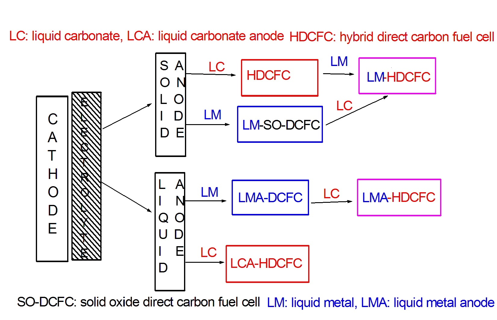
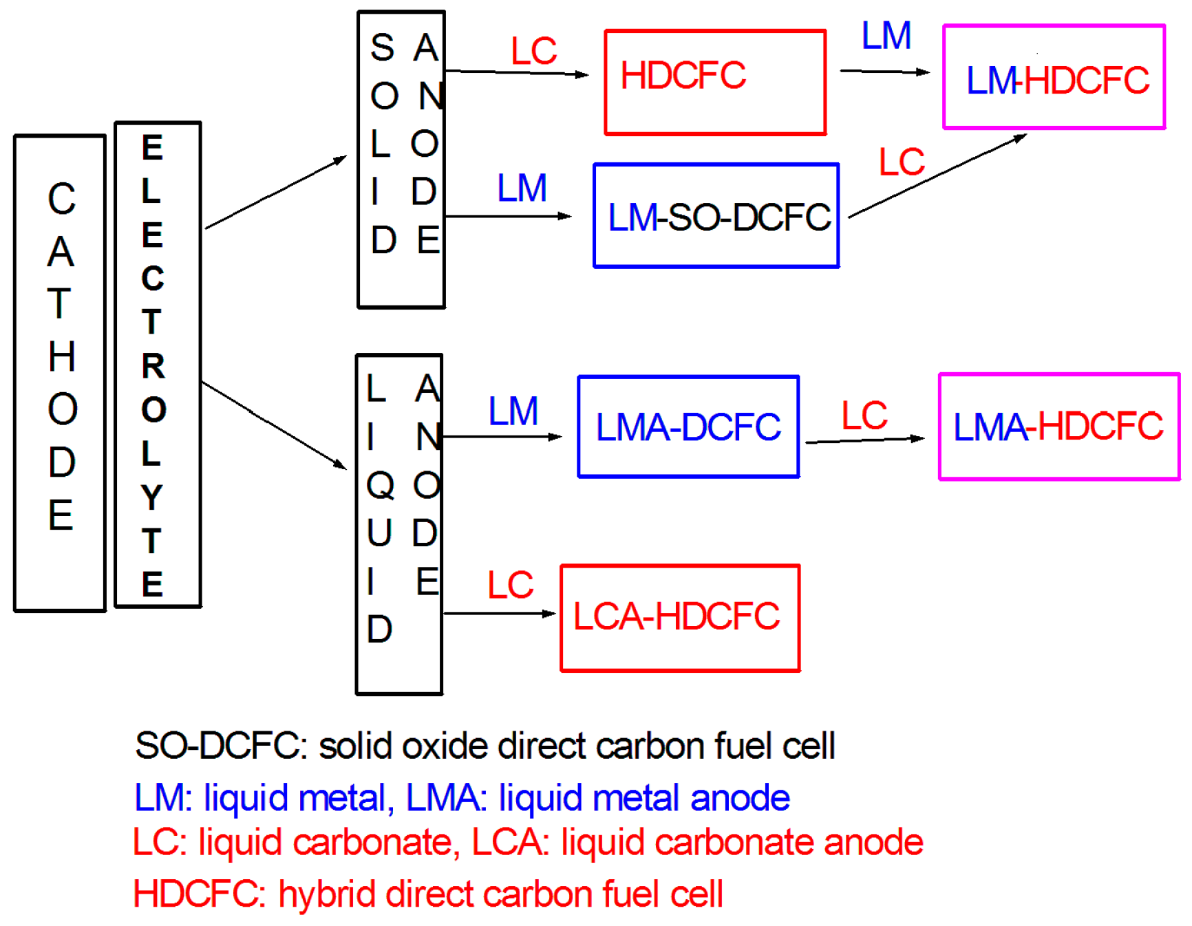
3.1. From MH-, MC-, and SO-DCFCs to HDCFCs
3.2. HDCFCs with a Liquid Carbonate/Carbon Anode
3.3. HDCFCs with a Solid Catalyst Anode
3.3.1. HDCFC Anode
3.3.2. HDCFC Electrolyte
3.3.3. HDCFC Cathode
3.3.4. Effect of Carbonate Presence (HDCFC vs. SO-DCFC) and Carbon/Carbonate Ratio
3.3.5. Effect of the Type of Carbon
3.3.6. Effect of Carbonate Mixture Composition
3.3.7. Effect of Catalyst Addition to the Fuel
3.3.8. Effect of Purge Gas
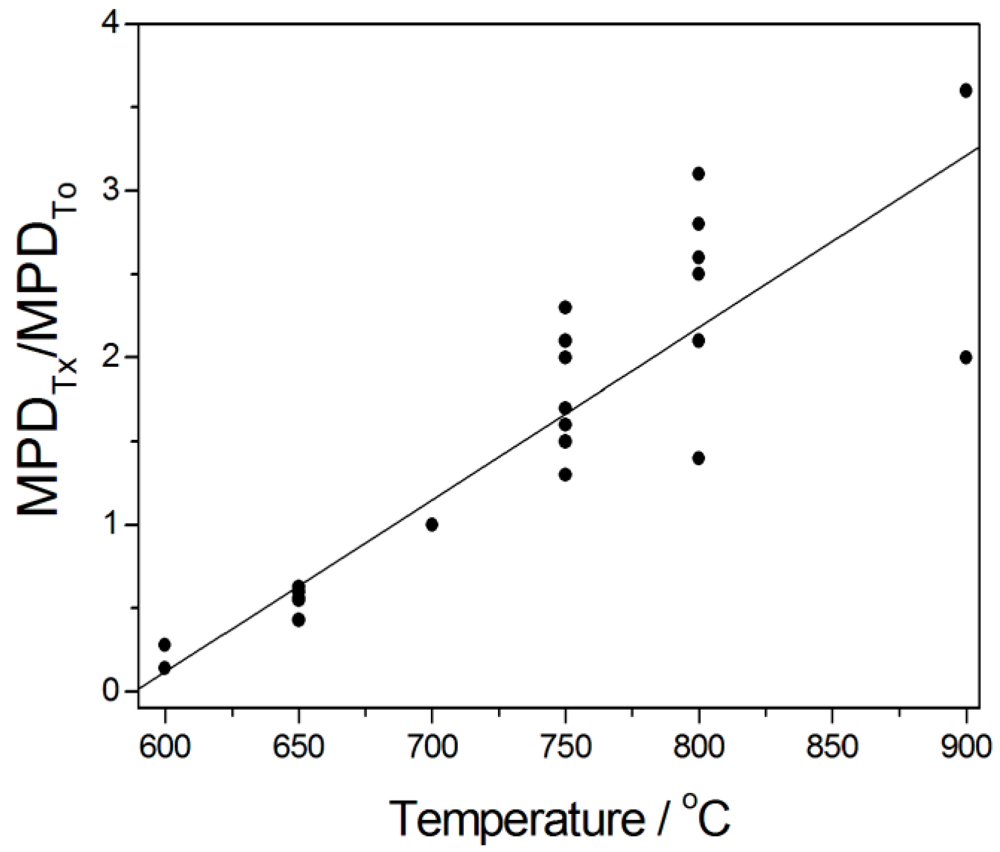
3.3.9. Effect of Temperature
4. LTA-HDCFC and Liquid-tin-Containing HDCFC
5. Conclusions and Perspectives
Funding
Data Availability Statement
Conflicts of Interest
Abbreviations
References
- Gur, T.M. Critical review of carbon conversion in carbon fuel cells. Chem. Rev. 2013, 113, 6179–6206. [Google Scholar] [CrossRef] [PubMed]
- Giddey, S.; Badwal, S.P.S.; Kulkarni, A.; Munnings, C. A comprehensive review of direct carbon fuel cell technology. Prog. Energy Combust. Sci. 2012, 38, 360–399. [Google Scholar] [CrossRef]
- Cao, D.; Sun, Y.; Wang, G. Direct carbon fuel cell: Fundamentals and recent developments. J. Power Sources 2007, 167, 250–257. [Google Scholar] [CrossRef]
- Jiang, C.; Ma, J.; Corre, G.; Jain, S.L.; Irvine, J.T.S. Challenges in developing direct carbon fuel cells. Chem. Soc. Rev. 2017, 46, 2889–2912. [Google Scholar] [CrossRef] [PubMed] [Green Version]
- Yu, F.; Han, T.; Wang, Z.; Xie, Y.; Wu, Y.; Jin, Y.; Yang, N.; Xiao, J.; Kawi, S. Recent progress in direct carbon solid oxide fuel cell: Advanced anode catalysts, diversified carbon fuels, and heat management. Int. J. Hydrogen Energy 2021, 46, 4283–4300. [Google Scholar] [CrossRef]
- Deleebeeck, L.; Hansen, K.K. Hybrid direct carbon fuel cells and their reaction mechanisms-a review. J. Solid State Electrochem. 2014, 18, 861–882. [Google Scholar] [CrossRef]
- Jewulski, J.; Skrzypkiewicz, M. Direct carbon fuel cells based on solid oxide electrolyte technology. Prz. Elektrotechniczny 2013, 89, 268–270. [Google Scholar]
- Toleuova, A.; Yufit, V.; Simons, S.; Maskell, W.C.; Brett, D.J.L. A review of liquid metal anode solid oxide fuel cells. J. Electrochem. Sci. Eng. 2013, 3, 91–105. [Google Scholar] [CrossRef] [Green Version]
- Abernathy, H.; Gemmen, R.; Gerdes, K.; Koslowske, M.; Tao, T. Basic properties of a liquid tin anode solid oxide fuel cell. J. Power Sources 2011, 196, 4564–4572. [Google Scholar] [CrossRef]
- Tao, T.; Bateman, L.; Bentley, J.; Slaney, M. Liquid tin anode solid oxide fuel cell for direct carbonaceous fuel conversion. ECS Trans. 2007, 5, 463–472. [Google Scholar] [CrossRef]
- Yentekakis, I.V.; Debenedetti, P.G.; Costa, B. Novel fused metal anode solid electrolyte fuel cell for direct coal gasification: A steady-state model. Ind. Eng. Chem. Res. 1989, 28, 1414–1424. [Google Scholar] [CrossRef]
- Yentekakis, I.V.; Debenedetti, P.G.; Costa, B.; Konsolakis, M.; Kiousis, V. Direct coal gasification with simultaneous production of electricity in a novel fused metal anode SOFC: A theoretical approach. Ionics 1999, 5, 460–471. [Google Scholar] [CrossRef] [Green Version]
- Jayakumar, A.; Javadekar, A.; Gissinger, J.; Vohs, J.M.; Huber, G.W.; Gorte, R.J. The stability of direct carbon fuel cells with molten Sb and Sb-Bi alloy anodes. AIChE J. 2013, 59, 3342–3348. [Google Scholar] [CrossRef]
- Gur, T.M. Direct Carbon Fuel Cell with Molten Anode. U.S. Patent n. 2006/023409, 19 October 2006. [Google Scholar]
- Jacobs, K.T. A new type of SOFC for conversion of high temperature heat to electricity without Carnot limitation. ECS Trans. 2011, 35, 573–582. [Google Scholar] [CrossRef]
- Javadekar, A.; Jayakumar, A.; Pujara, R.; Vohs, J.M.; Gorte, R.J. Molten silver as a direct carbon fuel cell anode. J. Power Sources 2012, 214, 239–243. [Google Scholar] [CrossRef]
- Jayakumar, A.; Hornés, A.; Vohs, J.M.; Gorte, R.J. A comparison of molten Sn and Bi for solid oxide fuel cell anodes. J. Electrochem. Soc. 2010, 157, B365–B369. [Google Scholar] [CrossRef] [Green Version]
- Jayakumar, A.; Vohs, J.M.; Gorte, R.J. Molten-metal electrodes for solid oxide fuel cells. Ind. Eng. Chem. Res. 2010, 49, 10237–10241. [Google Scholar] [CrossRef]
- Duan, N.-Q.; Cao, Y.; Hua, B.; Chi, B.; Pu, J.; Luo, J.; Jian, L. Tubular direct carbon solid oxide fuel cells with molten antimony anode and refueling feasibility. Energy 2016, 95, 274–278. [Google Scholar] [CrossRef]
- Cao, T.; Wang, H.; Shi, Y.; Cai, N. Direct carbon fuel conversion in a liquid antimony anode solid oxide fuel cell. Fuel 2014, 135, 223–227. [Google Scholar] [CrossRef]
- Jayakumar, A. Molten Metal Anodes for Direct Carbon-Solid Oxide Fuel Cells. Publicly Accessible Penn Dissertations. 646. 2012. Available online: https://repository.upenn.edu/edissertations/646 (accessed on 2 March 2023).
- Kim, B.-S.; Lee, J.; Yoon, H.S.; Kim, S.-K. Reduction of SnO2 with hydrogen. Mater. Trans. 2011, 52, 1814–1817. [Google Scholar] [CrossRef] [Green Version]
- Wang, H.; Shi, Y.; Cai, N. Characteristics of liquid stannum anode fuel cell operated in battery mode and CO/H2/carbon fuel mode. J. Power Sources 2014, 246, 204–212. [Google Scholar] [CrossRef]
- Tao, T.; Slaney, M.; Bateman, L.; Bentley, J.J. Anode polarization in liquid tin anode solid oxide fuel cell. ECS Trans. 2007, 7, 1389–1397. [Google Scholar] [CrossRef]
- Rastler, D. Program on Technology Innovation: Systems Assessment of Direct Carbon Fuel Cells Technology, Electric Power Research Report; Number 1016170; EPRI: Alto, CA, USA, 14 May 2008. [Google Scholar]
- Jayakumar, A.; Kungas, R.; Roy, S.; Javadekar, A.; Buttrey, D.J.; Vohs, J.M.; Gorte, R.J. A direct carbon fuel cell with a molten antimony anode. Energy Environ. Sci. 2011, 4, 4133–4137. [Google Scholar] [CrossRef]
- Ju, H.K.; Uhm, S.; Kim, J.W.; Song, R.-H.; Choi, H.; Lee, S.-H.; Lee, J. Enhanced anode interface for electrochemical oxidation of solid fuel in direct carbon fuel cells: The role of liquid Sn in mixed state. J. Power Sources 2012, 198, 36–41. [Google Scholar] [CrossRef]
- Xu, X.; Zhou, W.; Zhu, Z. Samaria-doped ceria electrolyte supported direct carbon fuel cell with molten antimony as the anode. Ind. Eng. Chem. Res. 2013, 52, 17927–17933. [Google Scholar] [CrossRef]
- Wang, H.; Cao, T.; Shi, Y.; Cai, N.; Yuan, W. Liquid antimony anode direct carbon fuel cell fueled with mass-produced de-ash coal. Energy 2014, 75, 555–559. [Google Scholar] [CrossRef]
- Khurana, S.; LaBarbera, M.; Fedkin, M.V.; Lvov, S.N.; Abernathy, H.; Gerdes, K. Performance evaluation of a liquid tin anode solid oxide fuel cell operating under hydrogen, argon and coal. J. Power Sources 2015, 274, 1049–1054. [Google Scholar] [CrossRef]
- Duan, N.-Q.; Tan, Y.; Yan, D.; Jia, L.; Chi, B.; Pu, J.; Jian, L. Biomass carbon fueled tubular solid oxide fuel cells with molten antimony anode. Appl. Energy 2016, 165, 983–989. [Google Scholar] [CrossRef]
- Jang, H.; Eom, J.; Ju, H.K.; Lee, J. Ameliorated performance in a direct carbon fuel cell using Sn mediator on Ni–YSZ anode surface. Catal. Today 2016, 260, 158–164. [Google Scholar] [CrossRef]
- Xu, K.; Li, Z.; Shi, M.; Xing, H.; Liu, H.; Li, X.; Hu, H.; Luo, G.; Yao, H. Investigation of the anode reactions in SO-DCFCs fueled by Sn–C mixture fuels. Proc. Comb. Inst. 2017, 36, 4435–4442. [Google Scholar] [CrossRef]
- Duan, N.; Xue, Y.; Ma, J.; Han, Y.; Xu, M.; Chi, B.; Pu, J.; Li, J. Liquid antimony-silver alloys as anodes for direct carbon solid oxide fuel cells. J. Power Sources 2018, 397, 170–176. [Google Scholar] [CrossRef]
- Cao, T.; Song, P.; Shi, Y.; Ghoniem, A.F.; Cai, N. Oxy-combustion of coal in liquid-antimony-anode solid oxide fuel cell system. Proc. Comb. Inst. 2019, 37, 2841–2848. [Google Scholar] [CrossRef]
- Levêque, G.; Abanades, S. Thermodynamic and kinetic study of the carbothermal reduction of SnO2 for solar thermochemical fuel generation. Energy Fuels 2014, 28, 1396–1405. [Google Scholar] [CrossRef]
- Zhou, X.; Oh, T.-S.; Vohs, J.M.; Gorte, R.J. Zirconia-based electrolyte stability in direct-carbon fuel cells with molten Sb anodes. J. Electrochem. Soc. 2015, 162, F567–F570. [Google Scholar] [CrossRef] [Green Version]
- Cao, T.; Cheng, Y.; Gorte, R.J.; Shi, Y.; Vohs, J.M.; Cai, N. Effect of grain boundary diffusion on electrolyte stability in direct carbon fuel cells with antimony anodes. Ceram. Int. 2017, 43, 16575–16579. [Google Scholar] [CrossRef]
- Ma, J.; Duan, N.; Han, Y.; Yan, D.; Chi, B.; Pu, J.; Li, J. Hot corrosion of Gd2O3-doped CeO2 electrolyte in solid oxide fuel cells with a liquid antimony anode. J. Power Sources 2018, 401, 397–402. [Google Scholar] [CrossRef]
- Ma, J.; Duan, N.; Han, Y.; Li, P.; Zhu, B.; Yan, D.; Chi, B.; Pu, J.; Li, J. Hot corrosion of yttria-stabilized zirconia by liquid antimony and antimony oxide. J. Power Sources 2019, 434, 226764. [Google Scholar] [CrossRef]
- Cao, T.; Huang, K.; Shia, Y.; Cai, N. Plasma-spray derived, corrosion-resistive electrolyte for liquid antimony anode direct carbon fuel cell. J. Power Sources 2018, 403, 76–81. [Google Scholar] [CrossRef]
- Singh, H.; Sidhu, B.S.; Puri, D.; Prakash, S. Use of plasma spray technology for deposition of high temperature oxidation/corrosion resistant coatings–a review. Mater. Corros. 2007, 58, 92–102. [Google Scholar] [CrossRef]
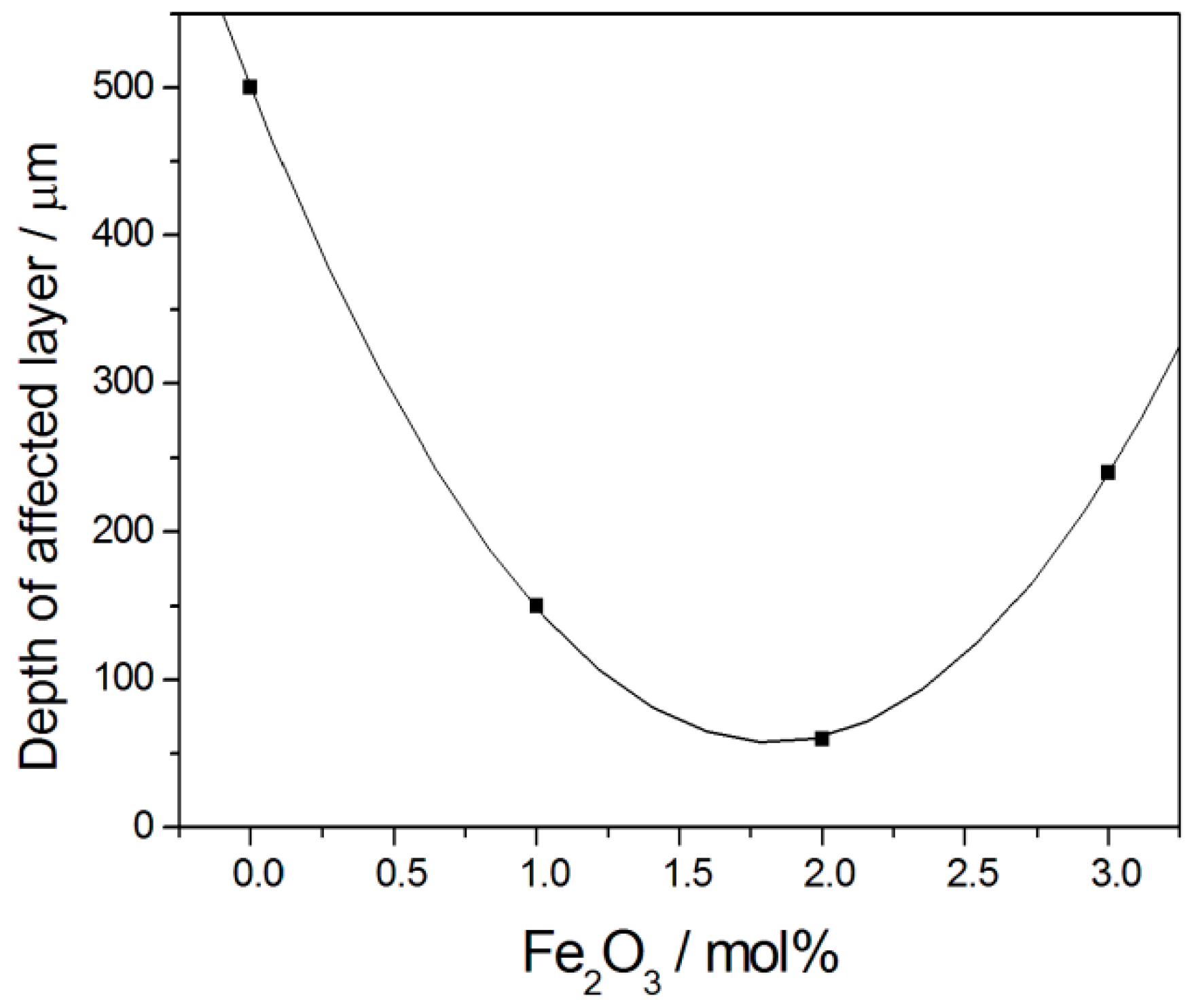
- Han, Y.; Ma, J.; Duan, N.; Yang, J.; Yan, D.; Chi, B.; Pu, J.; Li, J. Enhanced resistance of gadolinium-doped cerium oxide to liquid antimony and antimony oxide corrosions by addition of iron oxide. J. Power Sources 2020, 455, 227970. [Google Scholar] [CrossRef]
- Jacques, W.W. Harper’s New Monthly Magazine. V.94 1896–1897; Harper & Brothers: New York, NY, USA, 1987; pp. 144–150. [Google Scholar]
- Zecevic, S.; Patton, E.M.; Parharni, P. Carbon-air fuel cell without a reforming process. Carbon 2004, 42, 1983–1993. [Google Scholar] [CrossRef]
- Guo, L.; Calo, J.M.; DiCocco, E.; Bain, E.J. Development of a low temperature, molten hydroxide direct carbon fuel cell. Energy Fuels 2013, 27, 1712–1719. [Google Scholar] [CrossRef]
- Guo, L.; Calo, J.M.; Kearney, C.; Grimshaw, P. The anodic reaction zone and performance of different carbonaceous fuels in a batch molten hydroxide direct carbon fuel cell. Appl. Energy 2014, 129, 32–38. [Google Scholar] [CrossRef]
- Kacprzak, A.; Kobyłecki, R.; Bis, Z. The effect of coal thermal pretreatment on the electrochemical performance of molten hydroxide direct carbon fuel cell (MH-DCFC). J. Power Tech. 2017, 97, 382–387. [Google Scholar]
- Weaver, E.D.; Leach, S.C.; Bayce, A.F.; Nanis, L. Direct electrochemical generation of electricity from coal. SRI 1976, 97, 382–387, Menlo Park CA 94025 SAN. [Google Scholar]
- Antolini, E. The stability of molten carbonate fuel cell electrodes: A review of recent improvements. Appl. Energy 2011, 88, 4274–4293. [Google Scholar] [CrossRef]
- Kouchachvili, L.; Ikura, M. Performance of direct carbon fuel cell. Int. J. Hydrogen Energy 2011, 36, 10263–10268. [Google Scholar] [CrossRef]
- Cherepy, N.J.; Krueger, R.; Fiet, K.J.; Jankowski, A.F.; Cooper, J.F. Direct conversion of carbon fuels in a molten carbonate fuel cell. J. Electrochem. Soc. 2005, 152, A80–A87. [Google Scholar] [CrossRef]
- Chen, M.; Wang, C.; Niu, X.; Xhao, S.; Tang, J.; Zhu, B. Carbon anode in direct carbon fuel cell. Int. J. Hydrogen Energy 2010, 35, 2732–2736. [Google Scholar] [CrossRef]
- Vutetakis, D.G.; Skidmore, D.R.; Byker, H.J. Electrochemical oxidation of molten carbonate-coal slurries. J. Electrochem. Soc. 1987, 134, 3027–3034. [Google Scholar] [CrossRef]
- Ido, A.; Kawase, M. Development of a tubular molten carbonate direct carbon fuel cell and basic cell performance. J. Power Sources 2020, 449, 227483. [Google Scholar] [CrossRef]
- Cui, C.; Li, S.; Gong, J.; Wei, K.; Hou, X.; Jiang, C.; Yao, Y.; Ma, J. Review of molten carbonate-based direct carbon fuel cells. Mater. Renew. Sust. Energy 2021, 10, 12. [Google Scholar] [CrossRef]
- Metcalfe, C.; Kesle, O. Influence of microstructure on electrochemical performance of plasma sprayed Ni-YSZ anodes for SOFCs. Fuel Cells 2020, 20, 730–740. [Google Scholar] [CrossRef]
- Liu, C.; Pu, J.; Chen, X.; Ma, Z.; Ding, X.; Zhou, J.; Wang, S. Influence of anode’s microstructure on electrochemical performance of solid oxide direct carbon fuel cells. Int. J. Hydrogen Energy 2020, 46, 11784–11790. [Google Scholar] [CrossRef]
- Peelen, W.H.A.; Hemmes, K.; de Wit, J.H.W. Carbon a major energy carrier for the future? Direct carbon fuel cells and molten salt coal/biomass gasification. High Temp. Mater. Proc. 1998, 2, 471–482. [Google Scholar]
- Bonaccorso, A.D.; Irvine, J.T.S. Development of tubular hybrid direct carbon fuel cell. Int. J. Hydrogen Energy 2012, 37, 19337–19344. [Google Scholar] [CrossRef]
- Xie, H.; Zhai, S.; Liu, T.; Liao, H.; Zhang, Y.; Zhou, W.; Shao, Z.; Ni, M.; Chen, B. Cu-modified Ni foams as three-dimensional outer anodes for high-performance hybrid direct coal fuel cells. Chem. Eng. J. 2021, 410, 128239. [Google Scholar] [CrossRef]
- Nabae, Y.; Pointon, K.D.; Irvine, J.T.S. Electrochemical oxidation of solid carbon in hybrid DCFC with solid oxide and molten carbonate binary electrolyte. Energy Environ. Sci. 2008, 1, 148–155. [Google Scholar] [CrossRef]
- White, S.H.; Twardoch, U.M. The solubility and electrochemistry of alkali metal oxides in the molten eutectic mixture of lithium carbonate-sodium carbonate-potassium carbonate. J. Appl. Electrochem. 1989, 19, 901–910. [Google Scholar] [CrossRef]
- Nabae, Y.; Pointon, K.D.; Irvine, J.T.S. Ni/C slurries based on molten carbonates as a fuel for hybrid direct carbon fuel cells. J. Electrochen. Soc. 2009, 156, B716–B720. [Google Scholar] [CrossRef]
- Jiang, C.; Irvine, J.T.S. Catalysis and oxidation of carbon in a hybrid direct carbon fuel cell. J. Power Sources 2011, 196, 7318–7322. [Google Scholar] [CrossRef]
- Chien, A.C.; Irvine, J.T.S. Hybrid molten carbonate/solid oxide direct carbon fuel cells. In Molten Salts Chemistry, From Lab to Applications; Lantelme, F., Groult, H., Eds.; Elsevier: Amsterdam, The Netherlands, 2013; Chapter 19; pp. 403–414. [Google Scholar] [CrossRef]
- Badwal, S.; Giddey, S. The holy grail of carbon combustion—The Direct Carbon Fuel Cell technology. Mater. Forum 2010, 34, 181–185. Available online: http://hdl.handle.net/102.100.100/105843?index=1 (accessed on 8 June 2023).
- Lipilin, A.S.; Balachov, I.I.; Dubois, L.H.; Sanjurjo, A.; McKubre, M.C.; Crouch-Baker, S.; Hornbostel, M.D.; Tanzella, F.L. Liquid Anode Electrochemical Cell. U.S. Patent 2007/0269688 A1, 2007. [Google Scholar]
- Cooper, J.F. Direct conversion of coal derived carbon in fuel cell. In Recent Trends in Fuel Cell Science and Technology; Basu, S., Ed.; Springer: New York, NY, USA, 2007. [Google Scholar] [CrossRef]
- Jia, L.; Tian, Y.; Liu, Q.; Xia, C.; Yu, J.; Wang, Z.; Zhao, Y.; Li, Y. A direct carbon fuel cell with (molten carbonate)/(doped ceria) composite electrolyte. J. Power Sources 2010, 195, 5581–5586. [Google Scholar] [CrossRef]
- Elleuch, A.; Yu, J.; Boussetta, A.; Halouani, K.; Li, Y. Electrochemical oxidation of graphite in an intermediate temperature direct carbon fuel cell based on two-phases electrolyte. Int. J. Hydrogen Energy 2013, 38, 8514–8523. [Google Scholar] [CrossRef]
- Elleuch, A.; Boussetta, A.; Yu, J.; Halouani, K.; Li, Y. Experimental investigation of direct carbon fuel cell fueled by almond shell biochar: Part I. Physico-chemical characterization of the biochar fuel and cell performance examination. Int. J. Hydrogen Energy 2013, 38, 16590–16604. [Google Scholar] [CrossRef]
- Elleuch, A.; Halouani, K.; Li, Y. Investigation of chemical and electrochemical reactions mechanisms in a direct carbon fuel cell using olive wood charcoal as sustainable fuel. J. Power Sources 2015, 281, 350–361. [Google Scholar] [CrossRef]
- Elleuch, A.; Boussetta, A.; Halouani, K.; Li, Y. Experimental investigation of direct carbon fuel cell fueled by almond shell biochar: Part II. Improvement of cell stability and performance by a three-layer planar configuration. Int. J. Hydrogen Energy 2013, 38, 16605–16614. [Google Scholar] [CrossRef]
- Cantero-Tubilla, B.; Xu, C.; Zondlo, J.W.; Sabolsky, K.; Sabolsky, E.M. Investigation of anode configurations and fuel mixtures on the performance of direct carbon fuel cells (DCFCs). J. Power Sources 2013, 238, 227–235. [Google Scholar] [CrossRef]
- Xu, X.; Zhou, W.; Liang, F.; Zhu, Z. Optimization of a direct carbon fuel cell for operation below 700 °C. Int. J. Hydrogen Energy 2013, 38, 5367–5374. [Google Scholar] [CrossRef]
- Kaklidis, N.; Kyriakou, V.; Garagounis, I.; Arenillas, A.; Menendez, J.A.; Marnellos, G.E.; Konsolakis, M. Effect of carbon type on the performance of a direct or hybrid carbon solid oxide fuel cell. RSC Adv. 2014, 4, 18792–18800. [Google Scholar] [CrossRef]
- Kemma, M.; Stiller, C.; Selimovic, A.; Thorud, B.; Torisson, T.; Bolland, O. Planar and tubular solid oxide fuel cells: A comparison of transient process behaviors. ECS Proc. 2005, 2005–2007, 659. [Google Scholar] [CrossRef]
- Baharuddin, N.A.; Muchtar, A.; Sulong, A.B.; Abdullah, H. Fabrication methods for planar solid oxide fuel cells: A review. Adv. Mater. Res. 2013, 662, 396–401. [Google Scholar] [CrossRef]
- Khan, M.Z.; Iltaf, A.; Ishfaq, H.A.; Khan, F.N.; Tanveer, W.H.; Song, R.-H.; Mehran, M.T.; Saleem, M.; Hussain, A.; Masaud, Z. Flat-tubular solid oxide fuel cells and stacks: A Review. J. Asian Ceram. Soc. 2021, 9, 745–770. [Google Scholar] [CrossRef]
- Gil, V.; Gurauskis, J.; Deleebeeck, L.; Stamate, E.; Hansen, K.K. Cathode-supported hybrid direct carbon fuel cells. Int. J. Hydrogen Energy 2017, 42, 4311–4319. [Google Scholar] [CrossRef] [Green Version]
- Pointon, K.; Lakemana, B.; Irvine, J.; Bradley, J.; Jain, S. The development of a carbon–air semi fuel cell. J. Power Sources 2006, 162, 750–756. [Google Scholar] [CrossRef]
- Jiang, C.; Ma, J.; Bonaccorso, A.D.; Irvine, J.T.S. Demonstration of high power, direct conversion of waste-derived carbon in a hybrid direct carbon fuel cell. Energy Environ. Sci. 2012, 5, 6973–6980. [Google Scholar] [CrossRef]
- Xu, X.; Zhou, W.; Liang, F.; Zhu, Z. A comparative study of different carbon fuels in an electrolyte-supported hybrid direct carbon fuel cell. Appl. Energy 2013, 108, 402–409. [Google Scholar] [CrossRef]
- Chien, A.C.; Corre, G.; Antunes, R.; Irvine, J.T.S. Scaling up of the hybrid direct carbon fuel cell technology. Int. J. Hydrogen Energy 2013, 38, 8497–8502. [Google Scholar] [CrossRef]
- Deleebeeck, L.; Ippolito, D.; Hansen, K.K. Enhancing Hybrid Direct Carbon Fuel Cell anode performance using Ag2O. Electrochim. Acta 2015, 152, 222–223. [Google Scholar] [CrossRef] [Green Version]
- Chien, A.C.; Arenillas, A.; Jiang, C.; Irvine, J.T.S. Performance of direct carbon fuel cells operated on coal and effect of operation mode. J. Electrochem. Soc. 2014, 161, F588–F593. [Google Scholar] [CrossRef] [Green Version]
- Lee, J.-Y.; Song, R.-H.; Lee, S.-B.; Lim, T.-H.; Park, S.-J.; Shul, Y.G.; Lee, J.-W. A performance study of hybrid direct carbon fuel cells: Impact of anode microstructure. Int. J. Hydrogen Energy 2014, 39, 11749–11755. [Google Scholar] [CrossRef]
- Yu, J.; Zhao, Y.; Li, Y. Utilization of corn cob biochar in a direct carbon fuel cell. J. Power Sources 2014, 270, 312–317. [Google Scholar] [CrossRef]
- Fuente-Cuesta, A.; Jiang, C.; Arenillas, A.; Irvine, J.T.S. Role of coal characteristics in the electrochemical behavior of hybrid direct carbon fuel cells. Energy Environ. Sci. 2016, 9, 2868–2880. [Google Scholar] [CrossRef] [Green Version]
- Cantero-Tubilla, B.; Sabolsky, K.; Sabolsky, E.M.; Zondlo, J.W. Investigation of pretreated switchgrass, corn stover, and hardwood fuels in direct carbon fuel cells. Int. J. Electrochem. Sci. 2016, 11, 303–321. [Google Scholar] [CrossRef]
- Hao, W.; Mi, Y. Evaluation of waste paper as a source of carbon fuel for hybrid direct carbon fuel cells. Energy 2016, 107, 122–130. [Google Scholar] [CrossRef]
- Jiang, C.; Ma, J.; Arenillas, A.; Bonaccorso, A.D.; Irvine, J.T.S. Comparative study of durability of hybrid direct carbon fuel cells with anthracite coal and bituminous coal. Int. J. Hydrogen Energy 2016, 41, 18797–18806. [Google Scholar] [CrossRef] [Green Version]
- Yue, X.; Arenillas, A.; Irvine, J.T.S. Application of infiltrated LSCM-GDC oxide anode in direct carbon/coal fuel cells. Faraday Discuss. 2016, 190, 269–289. [Google Scholar] [CrossRef] [Green Version]
- Kaklidis, N.; Kyriakou, V.; Marnellos, G.E.; Strandbakke, R.; Arenillas, A.; Menéndez, J.A.; Konsolakis, M. Effect of fuel thermal pretreament on the electrochemical performance of a direct lignite coal fuel cell. Solid State Ion. 2016, 288, 140–146. [Google Scholar] [CrossRef] [Green Version]
- Li, S.; Pan, W.; Wang, S.; Meng, X.; Jiang, C.; Irvine, J.T.S. Electrochemical performance of different carbon fuels on a hybrid direct carbon fuel cell. Int. J. Hydrogen Energy 2017, 42, 16279–16287. [Google Scholar] [CrossRef] [Green Version]
- Sun, K.; Liu, J.; Feng, J.; Yuan, H.; He, M.; Xu, C.; Wang, Z.; Sun, W.; Qiao, J. Investigation of B-site doped perovskites Sr2Fe1.4X0.1Mo0.5O6−δ (X=Bi, Al, Mg) as high-performance anodes for hybrid direct carbon fuel cell. J. Power Sources 2017, 365, 109–116. [Google Scholar] [CrossRef]
- Wu, W.; Zhang, Y.; Ding, D.; He, T. A high-performing direct carbon fuel cell with a 3D architectured anode operated below 600 °C. Adv. Mater. 2018, 30, 1704745. [Google Scholar] [CrossRef] [Green Version]
- Liu, J.; Qiao, J.; Yuan, H.; Feng, J.; Sui, C.; Wang, Z.; Sun, W.; Sun, K. Ni modified Ce(Mn, Fe)O2 cermet anode for high-performance direct carbon fuel cell. Electrochim. Acta 2017, 232, 174–181. [Google Scholar] [CrossRef]
- Liu, J.; Yuan, H.; Qiao, J.; Feng, J.; Xu, C.; Wang, Z.; Sun, W.; Sun, K. Hierarchical hollow nanofiber networks for high-performance hybrid direct carbon fuel cells. J. Mater. Chem. A 2017, 5, 17216–17220. [Google Scholar] [CrossRef]
- Li, S.; Jiang, C.; Liu, J.; Tao, H.; Meng, X.; Connor, P.; Hui, J.; Wang, S.; Ma, J.; Irvine, J.T.S. Mechanism of enhanced performance on a hybrid direct carbon fuel cell using sawdust biofuels. J. Power Sources 2018, 383, 10–16. [Google Scholar] [CrossRef] [Green Version]
- Kaklidis, N.; Strandbakke, R.; Arenillas, A.; Menendez, J.A.; Konsolakis, M.; Marnellos, G.E. The synergistic catalyst-carbonates effect on the direct bituminous coal fuel cell performance. Int. J. Hydrogen Energy 2019, 44, 10033–10042. [Google Scholar] [CrossRef]
- Jiang, C.; Cui, C.; Ma, J.; Irvine, J.T.S. Insight into graphite oxidation in a NiO-based hybrid direct carbon fuel cell. Int. J. Hydrogen Energy 2020, 45, 10559–10568. [Google Scholar] [CrossRef]
- Xie, H.; Zhai, S.; Chen, B.; Liu, T.; Zhang, Y.; Ni, M.; Shao, Z. Coal pretreatment and Ag-infiltrated anode for high-performance hybrid direct coal fuel cell. Appl. Energy 2020, 260, 114197. [Google Scholar] [CrossRef]
- Ma, M.; Qiao, J.; Yang, X.; Xu, C.; Ren, R.; Sun, W.; Sun, K.; Wang, Z. Enhanced stability and catalytic activity on layered perovskite anode for high-performance hybrid direct carbon fuel cells. ACS Appl. Mater. Interfaces 2020, 12, 12938–12948. [Google Scholar] [CrossRef]
- Ma, M.; Yang, X.; Ren, R.; Xu, C.; Qiao, J.; Sun, W.; Sun, K.; Wang, Z. Honeycombed porous, size matching architecture for high-performance hybrid direct carbon fuel cell anode. ACS Appl. Mater. Interfaces 2020, 12, 30411–30419. [Google Scholar] [CrossRef]
- Yang, X.; Ma, M.; Xu, C.; Ren, R.; Qiao, J.; Sun, W.; Sun, K.; Wang, Z. Promoting effective electrochemical oxidation of CO by Cu-doping for highly active hybrid direct carbon fuel cell anode. J. Power Sources 2022, 521, 230966. [Google Scholar] [CrossRef]
- Wang, R.; Li, G.; Ma, Y.; Wang, T.; Chen, B.; Wei, T.; Dong, D. A high-performance hybrid direct carbon fuel cell with tandem catalysis in the dendritic channeled anode. Int. J. Hydrogen Energy 2023, 48, 9797–9804. [Google Scholar] [CrossRef]
- Benamira, M.; Ringuedé, A.; Hildebrandt, L.; Lagergren, C.; Vannier, R.-N.; Cassir, M. Gadolinia-doped ceria mixed with alkali carbonates for SOFC applications: II—An electrochemical insight. Int. J. Hydrogen Energy 2012, 37, 19371–19379. [Google Scholar] [CrossRef]
- Xu, X.; Zhou, W.; Zhu, Z. Stability of YSZ and SDC in molten carbonate eutectics for hybrid direct carbon fuel cells. RSC Adv. 2014, 4, 2398–2403. [Google Scholar] [CrossRef]
- Ma, M.; Yang, X.; Qiao, J.; Sun, W.; Wang, Z.; Sun, K. Progress and challenges of carbon-fueled solid oxide fuel cells anode. J. Energy Chem. 2021, 56, 209–222. [Google Scholar] [CrossRef]
- Kudo, T.; Hisamitsu, Y.; Kihara, K.; Mohamedi, M.; Uchida, I. X-ray diffractometric study of in situ oxidation of Ni in Li/K and Li/Na carbonate eutectic. J. Power Sources 2002, 104, 272–280. [Google Scholar] [CrossRef]
- Cayan, F.N.; Zhi, M.; Pakalapati, S.R.; Celik, I.; Wu, N.; Gemmen, R. Effects of coal syngas impurities on anodes of solid oxide fuel cells. J. Power Sources 2008, 185, 595–602. [Google Scholar] [CrossRef]
- Lussier, A.; Sofie, S.; Dvorak, J.; Idzerda, Y.U. Mechanism for SOFC anode degradation from hydrogen sulfide exposure. Int. J. Hydrogen Energy 2008, 33, 3945–3951. [Google Scholar] [CrossRef]
- Antolini, E. Direct propane fuel cells. Fuel 2022, 315, 123152. [Google Scholar] [CrossRef]
- Sreedhar, I.; Agarwal, B.; Goyal, P.; Singh, S.-A. Recent advances in material and performance aspects of solid oxide fuel cells. J. Electroanal. Chem. 2019, 848, 113315. [Google Scholar] [CrossRef]
- Ishihara, T.; Matsuda, H.; Takita, Y. Doped LaGaO3 perovskite type oxide as a new oxide ionic conductor. J. Am. Chem. Soc. 1994, 116, 3801–3803. [Google Scholar] [CrossRef]
- Huang, K.; Wan, J.H.; Goodenough, J.B. Increasing power density of LSGM-based solid oxide fuel cells using new anode materials. J. Electrochem. Soc. 2001, 148, A788–A794. [Google Scholar] [CrossRef]
- Kawahara, K.; Suda, S.; Suzuki, M.; Kawano, M.; Yoshida, H.; Inagaki, T. Effect of MgO formation in the vicinity of Ni-SDC/LSGM interface on SOFC performance. Solid State Ion. 2009, 180, 236–240. [Google Scholar] [CrossRef]
- dos Santos-Gómez, L.; León-Reina, L.; Porras-Vázquez, J.M.; Losilla, E.R.; Marrero-López, D. Chemical stability and compatibility of double perovskite anode materials for SOFCs. Solid State Ion. 2013, 239, 1–7. [Google Scholar] [CrossRef]
- Filonova, E.A.; Dmitriev, A.S.; Pikalov, P.S.; Medvedev, D.A.; Pikalova, E.Y. The structural and electrical properties of Sr2Ni0.75Mg0.25MoO6 and its compatibility with solid state electrolytes. Solid State Ion. 2014, 262, 365–369. [Google Scholar] [CrossRef]
- Martinez-Coronado, R.; Alonso, J.A.; Aguader, A.; Fernandez-Diaz, M.T. Optimized energy conversion efficiency in solid-oxide fuel cells implementing SrMo1−xFexO3−δ perovskites as anodes. J. Power Sources 2012, 208, 153–158. [Google Scholar] [CrossRef]
- Jiang, S.P. A comparison of O2 reduction reactions on porous (La,Sr)MnO3 and (La,Sr)(Co,Fe)O3 electrodes. Solid State Ion. 2002, 146, 1–22. [Google Scholar] [CrossRef]
- Sun, C.; Hui, R.; Roller, J. Cathode materials for solid oxide fuel cells: A review. J. Solid State Electrochem. 2010, 14, 1125–1144. [Google Scholar] [CrossRef]
- Jiang, C.; Ma, J.; Arenillas, A.; Irvine, J.T.S. Application of ternary carbonate in hybrid direct coal fuel cells. ECS Trans. 2014, 59, 281–287. [Google Scholar] [CrossRef]
- Malliaris, A.; Turner, D.T. Influence of particle size on the electrical resistivity of compacted mixtures of polymeric and metallic powders. J. Appl. Phys. 1971, 42, 614–618. [Google Scholar] [CrossRef]
- Ahn, S.Y.; Eom, S.Y.; Rhie, Y.H.; Sung, Y.M.; Moon, C.E.; Choi, G.M.; Kim, D.J. Application of refuse fuels in a direct carbon fuel cell system. Energy 2013, 51, 447–456. [Google Scholar] [CrossRef]
- Li, X.; Zhu, Z.H.; De Marco, R.; Bradley, J.; Dicks, A. Evaluation of raw coals as fuels for direct carbon fuel cells. J. Power Sources 2010, 195, 4051–4058. [Google Scholar] [CrossRef]
- Li, X.; Zhu, Z.H.; De Marco, R.; Dicks, A.; Bradley, J.; Liu, S.M.; Lu, G.Q. Factors that determine the performance of carbon fuels in the direct carbon fuel cell. Ind. Eng. Chem. Res. 2008, 47, 9670–9677. [Google Scholar] [CrossRef]
- Li, X.; Zhu, Z.; Chen, J.; De Marco, R.; Dicks, A.; Bradley, J.; Lu, G. Surface modification of carbon fuels for direct carbon fuel cells. J. Power Sources 2009, 186, 1–9. [Google Scholar] [CrossRef] [Green Version]
- Bie, K.; Fu, P.; Liu, Y.; Muhammad, A. Comparative study on the performance of different carbon fuels in a molten carbonate direct carbon fuel cell with a novel anode structure. J. Power Sources 2010, 460, 228101. [Google Scholar] [CrossRef]
- Dudek, M.; Sitarz, M.; Tomczyk, P. Effect of structural properties of carbon-based fuels on efficiency of direct carbon fuel cells. J. Solid State Electrochem. 2014, 18, 3023–3032. [Google Scholar] [CrossRef] [Green Version]
- Qiu, Q.; Zhou, M.; Cai, W.; Zhou, Q.; Zhang, Y.; Wang, W.; Liu, M.; Liu, J. A comparative investigation on direct carbon solid oxide fuel cells operated with fuels of biochar derived from wheat straw, corncob, and bagasse. Biomass Bioenergy 2019, 121, 56–63. [Google Scholar] [CrossRef]
- Cai, W.; Zhou, Q.; Xie, Y.; Liu, J.; Long, G.; Cheng, S.; Liu, M. A direct carbon solid oxide fuel cell operated on a plant derived biofuel with natural catalyst. Appl. Energy 2016, 179, 1232–1241. [Google Scholar] [CrossRef] [Green Version]
- Rady, A.C.; Giddey, S.; Kulkarni, A.; Badwal, S.P.S.; Bhattacharya, S.; Ladewig, B.P. Direct carbon fuel cell operation on brown coal. Appl. Energy 2014, 120, 56–64. [Google Scholar] [CrossRef]
- Xu, K.; Dong, J.; Hu, H.; Zhu, X.; Yao, H. Effect of ash components on the performance of solid oxide electrolyte-based carbon fuel cells. Energy Fuels 2018, 32, 4538–4546. [Google Scholar] [CrossRef]
- Liu, G.; Zhang, Y.; Zhou, A.; Wang, J.; Cai, J.; Dang, Y. A Comparative study on the performance of direct carbon solid oxide fuel cell powered with different rank coals. Energy Fuels 2021, 35, 6835–6844. [Google Scholar] [CrossRef]
- Wu, X.; Radovic, L. Catalytic oxidation of carbon/carbon composite materials in the presence of potassium and calcium acetates. Carbon 2006, 43, 333–344. [Google Scholar] [CrossRef]
- Dudek, M.; Tomczyk, P. Composite fuel for direct carbon fuel cell. Catal. Today 2011, 176, 388–392. [Google Scholar] [CrossRef]
- Wu, Y.; Su, C.; Zhang, C.; Ran, R.; Shao, Z. A new carbon fuel cell with high power output by integrating with in situ catalytic reverse Boudouard reaction. Electrochem. Commun. 2009, 11, 1265–1268. [Google Scholar] [CrossRef]
- Tang, Y.; Liu, J. Effect of anode and Boudouard reaction catalysts on the performance of direct carbon solid oxide fuel cells. Int. J. Hydrogen Energy 2010, 35, 11188–11193. [Google Scholar] [CrossRef]
- Konsolakis, M.; Kaklidis, N.; Kyriakou, V.; Garagounis, I.; Kraia, T.; Arenillas, A.; Menéndez, J.A.; Strandbakke, R.; Marnellos, G.E. The combined impact of carbon type and catalyst-aided gasification process on the performance of a direct carbon solid oxide fuel cell. Solid State Ion. 2018, 317, 268–275. [Google Scholar] [CrossRef] [Green Version]
- Skrzypkiewicz, M.; Lubarska-Radziejewska, I.; Jewlski, J. The effect of Fe2O3 catalyst on direct carbon fuel cell performance. Int. J. Hydrogen Energy 2015, 40, 13090–13098. [Google Scholar] [CrossRef]
- Cai, W.; Liu, J.; Yu, F.; Zhou, Q.; Zhang, Y.; Wang, X.; Liu, M.; Ni, M. A high performance direct carbon solid oxide fuel cell fueled by Ca-loaded activated carbon. Int. J. Hydrogen Energy 2017, 42, 21167–21176. [Google Scholar] [CrossRef]
- Rady, A.C.; Giddey, S.; Kulkami, A.; Badwal, S.P.S.; Bhattacharya, S. Catalytic gasification of carbon in a direct carbon fuel cell. Fuel 2016, 180, 270–277. [Google Scholar] [CrossRef]
- Cao, T.; Song, P.; Shi, Y.; Cai, N. Carbonate-tin composite liquid anode for solid oxide direct carbon fuel cell. Int. J. Hydrogen Energy 2017, 42, 6324–6331. [Google Scholar] [CrossRef]
- Li, S.; Jiang, C.; Irvine, J.T.S. Investigation of tin liquid anode on hybrid direct carbon fuel cells. ECS Trans. 2019, 91, 523–528. [Google Scholar] [CrossRef] [Green Version]
- Tsipis, E.; Waerenborgh, J.; Kharton, V. Grain-boundary states in solid oxide electrolyte ceramics processed using iron oxide sintering aids: A Mössbauer spectroscopy study. J. Solid State Electrochem. 2017, 21, 2965–2974. [Google Scholar] [CrossRef]


| Molten Metal | Anode//Electrolyte//Cathode | Fuel | T °C | OCV V | MPD mWcm−2 | PD (mWcm−2) at Constant j (mA cm−2) or V | Ref. |
|---|---|---|---|---|---|---|---|
| Cu | Cu//YSZ//La0.9Sr0.1(Mn,Fe,Co)O3−δ | Desulfurized coke | 1100 | 1.2 | 1700 | [15] | |
| Sb | Sb//ScSZ//La0.8Sr0.2FeO3(LSF)-ScSZ, Sb 2 g | Sugar char 0.5 g | 700 | 0.75 | 360 | 300 (0.5 V) Stable > 12 h | [26] |
| Sb SbBi * | Sb(Sb0.8Bi0.2)//ScSZ//La0.8Sr0.2FeO3(LSF)-ScSZ, Sb 10 g, SbBi 13.5 g | 60% charcoal 40% rice starch, 13 g, refueling | 700 | 0.75 0.738 | ca. 250 (0.5 V) (>200 h) | [13] | |
| Ag Ag0.5Sb0.5 | Ag//YSZ//LSF, Ag 2 g AgSb//YSZ//LSF, Sb 2g | Charcoal, 0.5 g | 1000 700 | 1.12 0.75 | ≈8 ≈60 | - | [16] |
| Sn | Ni/YSZ//YSZ//La0.8Sr0.2MnO3 (LSM) | Carbon black (Cb) Sn + Cb (Sn:Cb 1:3) Sn + Ni + Cb | 900 900 900 | 0.68 0.71 0.73 | 14 60.5 105 | [27] | |
| Sb | Sb//SmDC//Ba0.5Sr0.5Co1−xFexO3−δ (BSCF) | Carbon | 650 700 750 | 222 268 327 | [28] | ||
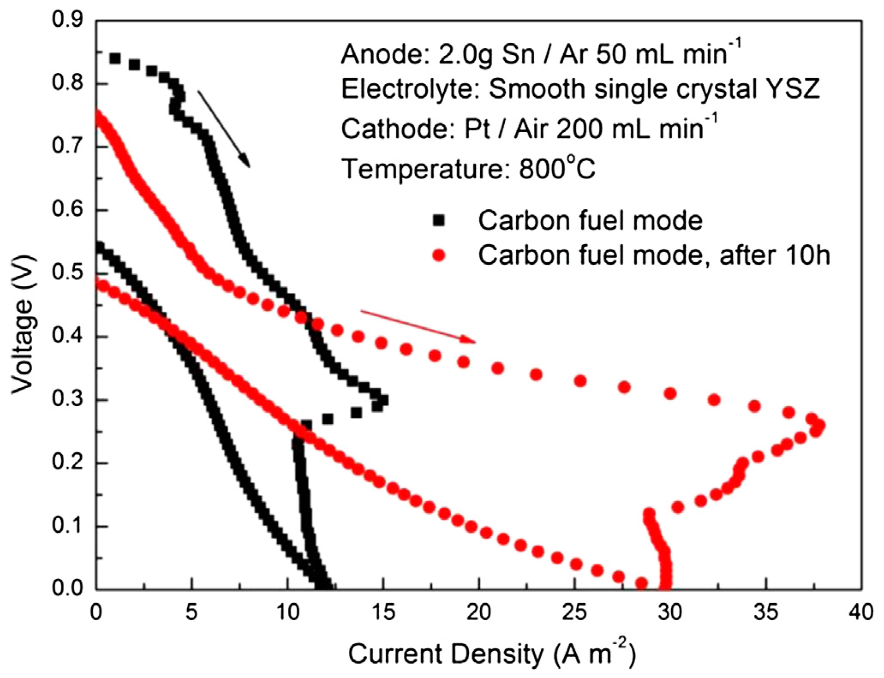
| Sn | Sn//YSZ//Pt, Sn 2 g Sn//YSZ//Pt after 10 h | Carbon black 0.2 g | 800 800 | 0.85 0.75 | ≈0.5 ≈1.0 | - | [22] |
| Sb | Sb//YSZ//Pt, Sb 10 g | De-ash coal, 1 g after discharging | 800 | 0.704 | 72 | 66 (0.3 V) Stable > 2 h | [29] |
| Sb | Sb//YSZ//Pt, Sb 10 g | De-ash coal, 1 g after discharging Well-mixed Sb and C (direct carbon oxidation) | 900 800 | 0.66 1.083 | ≈100 ≈23 | 98 (0.3 V) Stable > 1 h | [20] |
| Sn | Sn//YSZ//LSM | Coal | 900 | 0.885 | - | [30] | |
| Sb | Sb//YSZ//La0.6Sr0.4Co0.2Fe0.8O3−Gd2O3doped CeO2 (LSCF-10GDC), Sb 5 g | Activated carbon 1 g | 800 | 0.69 (no C) | 304 (no C) | 200 (400) Stable > 6 h | [19] |
| Sb | Sb//YSZ//LSCF-10GDC, Sb 5 g | Pyrolyzed cocoanut shells (CAC), SSA 749 m2 g−1 pyrolyzed fresh corn starch (PCS) SSA 0.2 m2 g−1 2g | 750 800 | 0.712 (no C) 0.69 (no C) | 196 (no C) 304 (no C) | CAC 180 (400), 14 h PCS 180 (400), 1 h CAC 208 (400), 11 h PCS 208 (400), 11 h | [31] |
| Sn | Ni/YSZ//YSZ//LSM Sn/Ni/YSZ//YSZ//LSM, Sn 15 mg Sn/Ni/YSZ//YSZ//LSM, Sn 60 mg Ni//YSZ//LSM Sn/Ni/YSZ//YSZ//LSM, Sn 15 mg Sn/Ni7YSZ//YSZ//LSM, Sn 60 mg | Carbon black 0.3 g | 750 850 | 0.91 0.95 0.85 0.88 0.91 0.87 | 20 62 30 68 136 95 | [32] | |
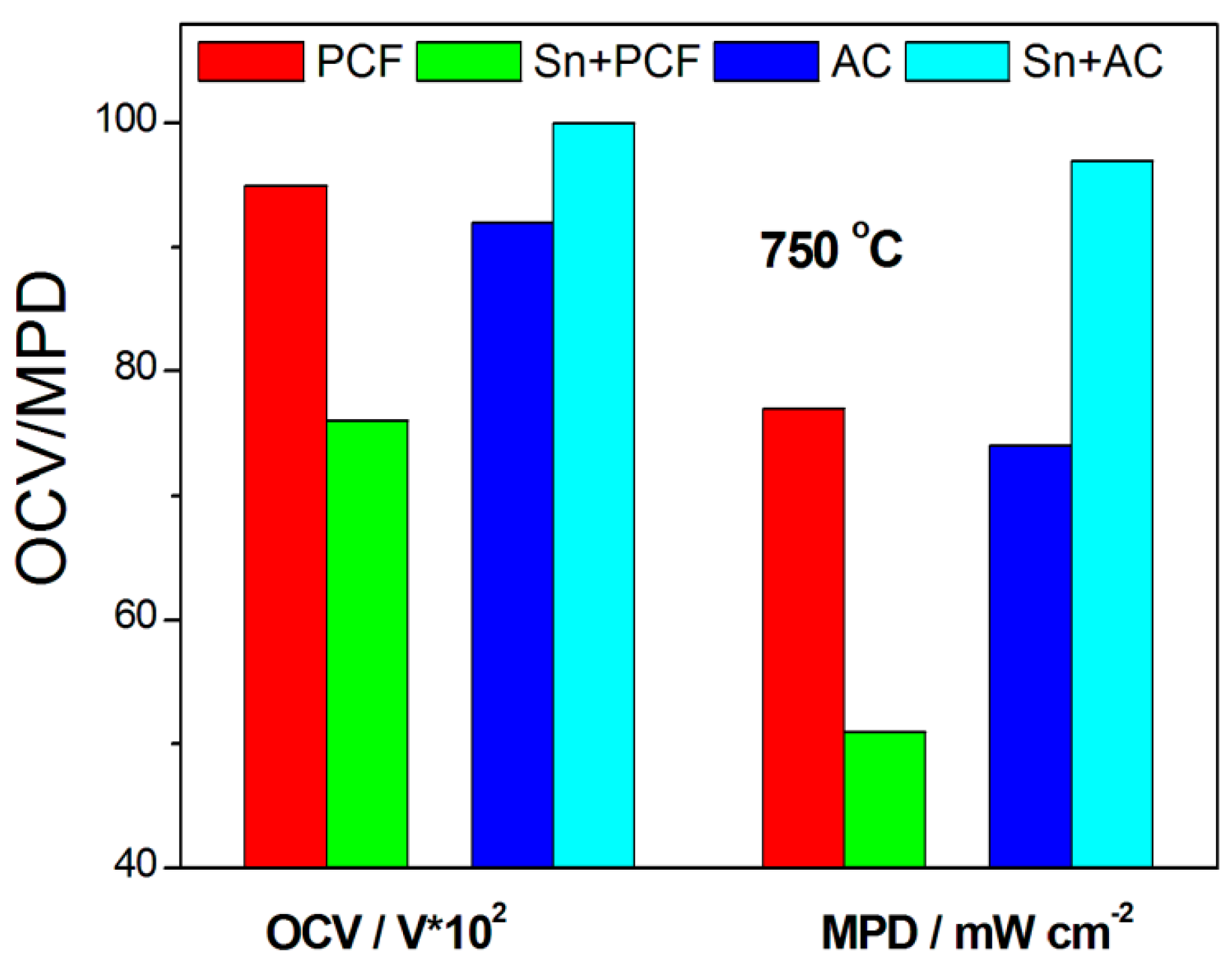
| Sn | Ni/YSZ//YSZ//GDC/LSCF/GDC | Sn Lignite (PCF) PAC Sn + PCF (Sn:C 4:1) Sn + PAC (Sn:C 4:1) Sn PCF PAC Sn + PCF (Sn:C 4:1) Sn + PAC (Sn:C 4:1) | 750 850 | 0.86 0.95 0.92 0.76 1.0 0.88 1.01 0.97 0.91 1.03 | 59 77 74 51 97 89 123 119 75 161 | [33] | |
| Sb Sb0.9Ag0.1 Sb0.8Ag 0.2 Sb0.7Ag 0.3 | Sb1−xAgx//YSZ//LSCF-10GDC, Sb 5 g | CAC, 2 g | 800 | 0.71 0.74 0.705 0.7 | 226 225 203 187 | [34] | |
| Sb | Sb//Sb2O3/YSZ//LSM/YSZ | De-ash anthracite coal, 10 g refueling | 700 750 | 0.745 0.723 | 35 47 | 25 (0.35 V) Stable > 40 h | [35] |
| Fuel//Carbonate Ratio | Anode//Electrolyte//Cathode | T °C | MPD mW cm−2 | Refs. |
|---|---|---|---|---|
| S carbon black//Li/K 62/38% 8:1 molar | Ni mesh//YSZ//Pt | 700 | 10 mW (not normalized) * | [82] |
| S carbon black//Li/K 62/38% 1:1 molar, 1.9 g XC carbon black//Li/K 62/38% 1:1 molar ratio, 1.9 g | NiO/YSZ//YSZ//LSM/YSZ | 700 900 700 900 | 0.5 (no carbonate) 3.6 15.5 (no carbonate) 13 6.4 12.6 | [62] |
| Ni-carbon black//Li/K 62/38% 1:1 molar | NiO/YSZ//YSZ//LSM/YSZ | 550 700 | 0.16 (Ni 0 wt%) 1.18 (Ni 50 wt%) 2.2 (Ni 0 wt%) 5.8 (Ni 50 wt%) | [64] |
| XC carbon black//Li/K 62/38% 4:1 molar | NiO/YSZ//YSZ//LSM/YSZ | 700 800 | 20 50 | [65] |
| Pirolized MDF//Li/K 62/38% 4:1 weight | NiO/YSZ//YSZ//LSM/YSZ NiO/YSZ//YSZ//LSCF/GDC | 750 | 70 (electrolyte-supported) 390 (anode-supported, N2) 500 (CO2 purge gas) 878 (flowing air cathode) | [83] |
| Pirolized MDF//Li/K 62/38% 4:1 molar | NiO/GDC//GDC//LSM/GDC | 700 750 | 40 mW (not normalized) * 90 mW (not normalized) * | [60] |
| carbon black//Li/K 62/38% 4:1 weight | -//YSZ//LSCF/GDC denseGDC//YSZ//LSCF/GDC dense/porousGDC//YSZ//LSCF/GDC | 775 | 7 42 70 | [75] |
| graphite (<20 μm)//Li/K 62/38% 1:1 molar activated carbon (125–250 μm, AC250)//Li/K 62/38%. 1:1 molar | NiO/SDC//SDC//Ba0.5Sr0.5Co0.8Fe0.2O3−δ(BSCF) PorousSDC//SDC//BSCF NiO/SDC//SDC//BSCF -//SDC//BSCF | 650 | 37 41 89 113 | [76] |
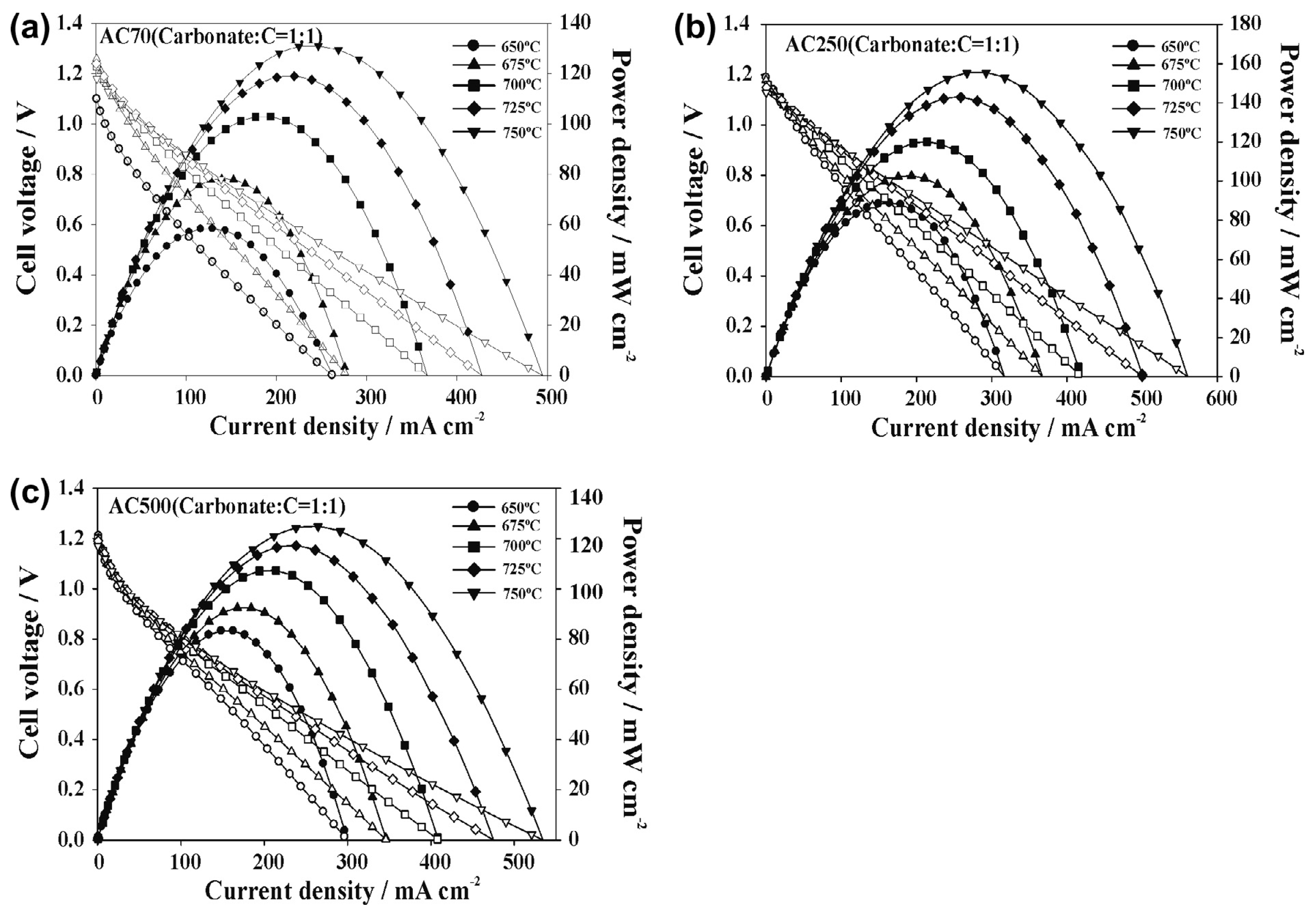
| German creek (200 μm) (GK200) Graphite carbon (20 μm) (GC20) Activated carbon (70 μm) (AC70) Activated carbon (250 μm) Activated carbon (500 μm) For all carbons C//Li/K 62/38% 1:1 molar | NiO/SDC//SDC//BSCF | 650 700 750 650 700 750 650 700 750 750 750 | 40 63 85 42 75 113 60 100 132 158 126 | [84] |
| Activated Carbon (XC-72R)//Li/K 62/38%. 1:1 weight Pirolized MDF//Li/K 62/38% //Ni(NO3)2, 4:1:1 | NiO/YSZ//YSZ//LSCF | 700 800 800 | 37 (after 17 h at 0.7 V) 53 (after 17 h at 0.7 V) 92 (after load at 0.8 V, no gas flow) | [85] |
| Almond shell biochar/Li/Na 66/33%. 1:9 weight | NiO/SDC//SDC//Li/Na 66/33%(70:30wt%)//LixNi1−xO | 600 650 700 | 20 64 148 | [74] |
| Anthracite coal Bituminous coal Demineralizated bituminous coal Pine Charcoal For all carbons C//Li/K 62/38% 4:1 weight | Cu/CeO2//YSZ//Ag | 750,800 750 800 750 800 750 800 | 1.2 (all MPD under 3.7 CO2 flow) 2.7 4.8 3.3 5.3 7 12 | [77] |
| Carbon black//Li/K 62/38%//- Carbon black//Li/K 62/38%//Ag2O 4:1:1 weight | NiO/YSZ//YSZ//LSM/YSZ | 800 | 22 58 | [86] |
| Graphite Anthracite coal milled Anthracite coal milled demineral Bituminous coal milled Bituminous coal milled deminer Pine Charcoal Activated Carbon (XC-72R) For all carbons C//Li/K 62/38% 4:1 weight | NiO/13YSZ//YSZ//LSM/YSZ | 700 | 67 (all PD at 0.5 V) 97 103 115 165 96 145 | [87] |
| Carbon Super P//Li/K 62/38% 1:1.5 weight | NiO/YSZ//YSZ//LSM/YSZ PorousNiOa/YSZ//YSZ//LSM/YSZ PorousNiOb/YSZ//YSZ//LSM/YSZ SA PorousNiOa > SA PorousNiOb | 750 850 750 850 750 850 | 127 265 105 359 80 287 | [88] |
| Corn cob biochar/Li/Na 66/33%. 1:9 weight | NiO/SDC//SDC/Li/NaCO3(70:30wt%)//LixNi1−xO | 600 650 700 750 | 32 68 113 185 | [89] |
| Anthracite coal Carbonized anthracite coal Bituminous coal Carbonized bituminous coal For all carbons C//Li/K 62/38% 4:1 weight | NiO/YSZ//YSZ//LSM/YSZ | 750 | 45 45 68 40 | [90] |
| Carbon black Bituminous coal Torrefied switchgrass Pyrolyzed switchgrass (charcoal) Torrefied hardwood Torrefied corn stover For all carbons C//Li/K 62/38% 16:1 volume | dense/porousGDC//YSZ//LSCF/GDC | 800 | 118 94 121 102 118 110 | [91] |
| Magazine paper carbon Newspaper carbon Activated charcoal C//Li/K/Na 32/35/33% 1:1 weight | NiO/SDC//SDC//LSCF | 650 | 172 136 93 But lower durability than AC | [92] |
| Anthracite coal I (low volatile) Anthracite coal II (low volatile) Bituminous coal I (low ash) Bituminous coal II (low ash) For all carbons C//Li/K 62/38% 4:1 weight | NiO/YSZ//YSZ//LSM/YSZ | 750 | 60 58 62 72 | [93] |
| Pyrolyzed organic xerogel Bituminous coal II Pyrolyzed organic xerogel For all carbons C//Li/K 62/38% 4:1 weight | (La, Sr)(Cr, Mn)O3 (LSCM)-GDC//YSZ//LSM/YSZ/LSM NiO/YSZ//YSZ//LSM/YSZ/LSM | 750 | 45 60 23 | [94] |
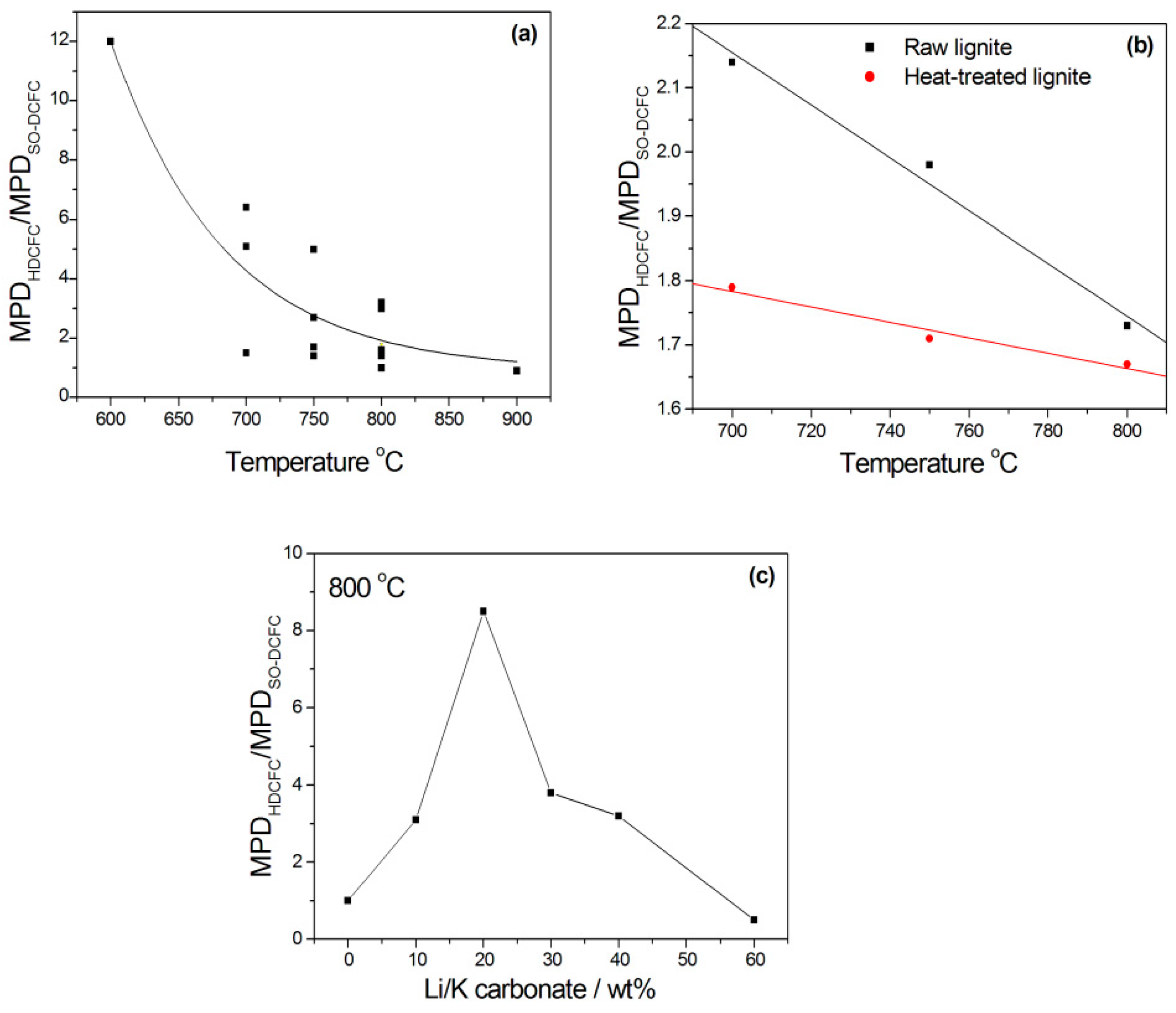
| Lignite Lignite 800 | Co/CeO2//YSZ//Ag | 700 750 800 700 750 800 | 5 (no carbonate) 10.7 9.2 (no carbonate) 18.2 13.2 (no carbonate) 22.8 7.1 (no carbonate) 12.7 12.2 (no carbonate) 20.9 15.3 (no carbonate) 25.5 | [95] |
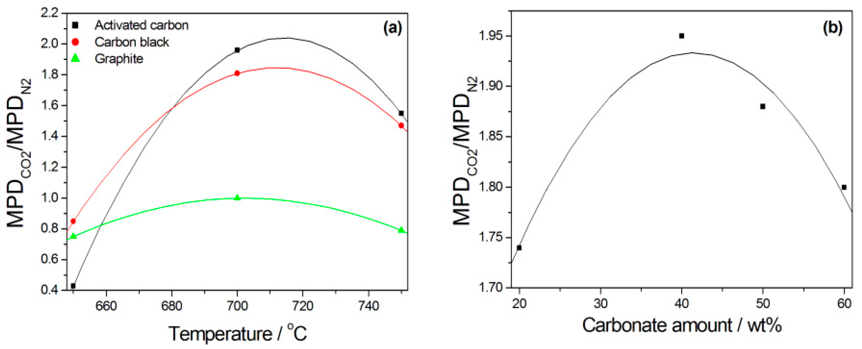
| Activated carbon Carbon black Graphite For all carbons C//Li/K 62/38% 4:1 molar | NiO/YSZ//YSZ//LSCF/GDC | 700 800 700 800 700 800 700 800 700 800 700 800 | 79 (N2 purge gas) 535 155 (CO2 purge gas) 489 21 (N2 purge gas) 224 38 (CO2 purge gas) 380 28 (N2 purge gas) 154 28 (CO2 purge gas) 170 | [96] |
| Activated carbon//Li/K 62/38% 4:1 weight | SFXM//LSGM//LSFC SFXM (Sr2Fe1.4X0.1Mo0.5O6−δ, X = Bi, Al, Mg) | 700 750 800 800 800 | 141 (SFBM anode) 287 399 293 (SFAM anode) 181 (SFMM anode) | [97] |
| Graphite//Li/K 62/38% 4:1 weight | 3D NiO/GDC//GDC-Li/Na2CO3//Sm0.5Sr0.5CoO3(SSC) | 500 550 600 | 143 196 325 | [98] |
| Carbon black//Li/K 62/38% 4:1 weight | NiO/YSZ//YSZ//LSM/YSZ | 755 | 44 (anode-supported) 75 (cathode-supported) | [81] |
| Activated carbon//Li/K 62/38% 4:1 weight | Ni(50%)-Ce0.6Mn0.3Fe0.1O2 (Ni-CMF)cermet/SDC//LSGM//LSCF CMF//LSGM//LSCF | 700 750 800 800 | 227 478 581 172 | [99] |
| Activated carbon//Li/K 62/38% 4:1 weight | Ni-CMFnanofibers//LSGM//LSCF | 800 | 230 (0% Ni) 320 (22% Ni) 530 (30% Ni) 370 (30% Ni) 200 (58% Ni) | [100] |
| Pyrolyzed sawdust//Li/K 62/38% Various C/carbonate ratios | Ni/YSZ//YSZ//GDC/LSCF/GDC | 750 | 550(40% carbon) (CO2) 731 (50% carbon) 750 (60% carbon) 600 (80% carbon) 306 (40% carbon) (N2) 388 (50% carbon) 384 (60% carbon) 344 (80% carbon) | [101] |
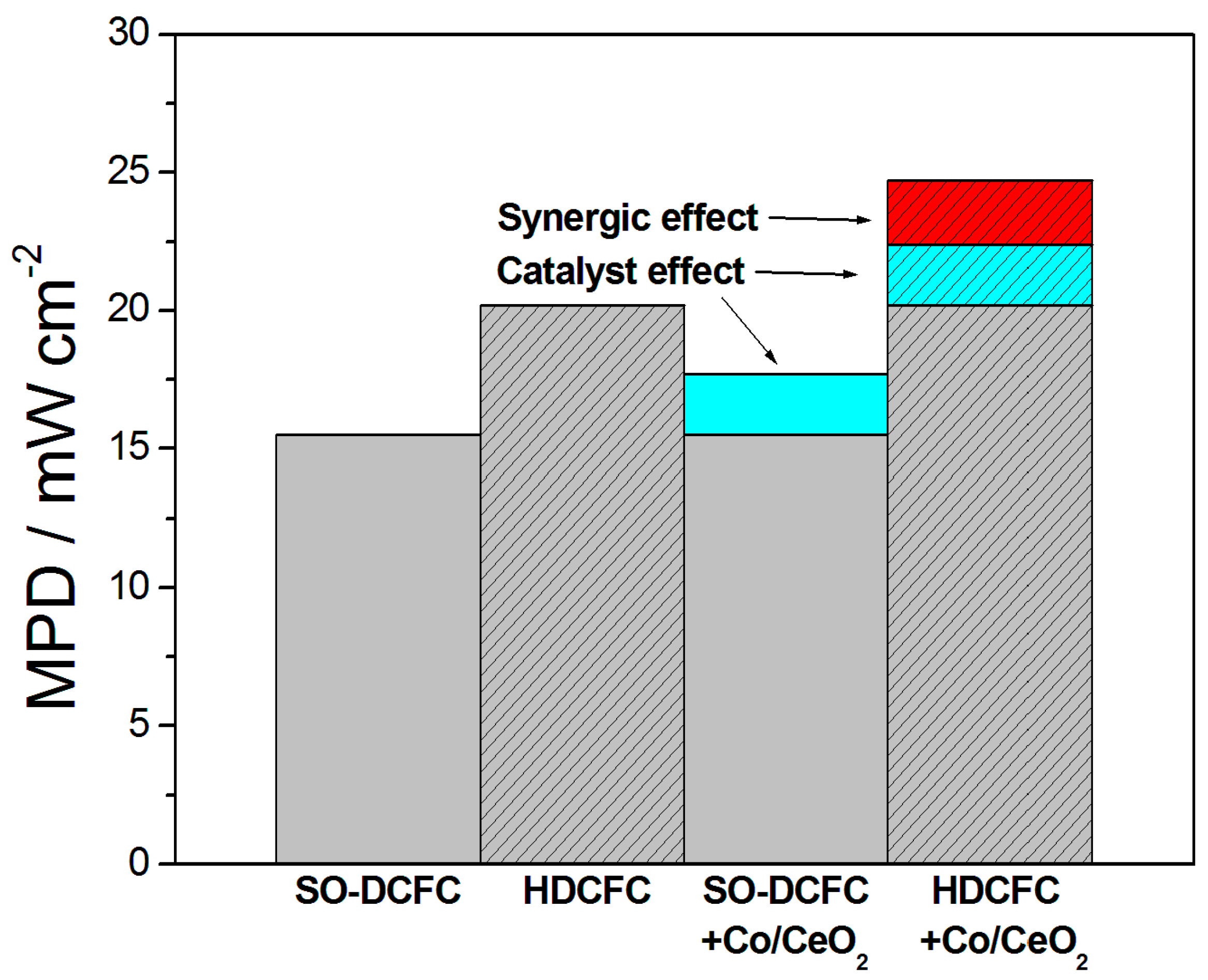
| Bituminous coal//Li/K 62/38%//Co/CeO2 C/carbonate/Co x:y:z weight | Co/CeO2//YSZ//Ag | 700 800 | 6.0 (4:0:0) 7.2 (4:0:1) 7.7 (4:2:0) 10.9 (4:2:1) 15.5 (4:0:0) 17.7 (4:0:1) 20.2 (4:2:0) 24.7 (4:2:1) | [102] |
| Graphite carbon Carbon black Pyrolyzed biomass (charcoal) For all carbons C//Li/K 62/38% 4:1 weight | NiO/YSZ//YSZ//LSM/YSZ | 750 | 49 25 52 | [103] |
| Bituminous coal Charcoal (by pyrolysis BiC) Modified charcoal (acid-treated) For all carbons C//Li/K 62/38% 4:1 weight | NiO/YSZ//YSZ//SDC/SrSc0.175Nb0.025Co0.8O3−d(SSNC) Ag/NiO/YSZ//YSZ//SDC/SSNC | 750 | 282 297 366 403 | [104] |
| Activated carbon//Li/K 62/38% 4:1 weight | (PrBa)0.95Fe1.8−xCuxNb0.2O5+δ (PBFCN)//YSZ//LSM/YSZ | 800 | 210 (x = 0.1) 275 (x = 0.2) 325 (x = 0.3) 431 (x = 0.4) | [105] |
| Activated carbon//Li/K 62/38% 4:1 weight | PorousPBFCN//YSZ//LSM/YSZ | 800 | 765 (x = 0.4) | [106] |
| Anthracite 250 mesh/Li/K 62/38% 7:3 weight | metal foam/NiO/SDC//YSZ//SDC|SSNC | 750 | 306 (no metal foam) 349 (30 PPI Ni foam) 389 (90 PPI Ni foam) 378 (CuNi foam) | [61] |
| Activated carbon//Li/K 62/38% 4:1 weight | Sr2Fe1.5Mo0.5O6−δ (SFM)//LSGM//LSCF Sr2Fe1.3Cu0.2Mo0.5O6−δ (SFCM)//LSGM//LSCF | 650 700 750 800 650 700 750 800 | 51 92 143 286 100 156 315 489 | [107] |
| Activated carbon//Li/K 62/38% 7:3 weight | Pd/GDC-Ni-Cu/GDC //YSZ-GDC//LSCF/GDC | 750 | 556 | [108] |
Disclaimer/Publisher’s Note: The statements, opinions and data contained in all publications are solely those of the individual author(s) and contributor(s) and not of MDPI and/or the editor(s). MDPI and/or the editor(s) disclaim responsibility for any injury to people or property resulting from any ideas, methods, instructions or products referred to in the content. |
© 2023 by the author. Licensee MDPI, Basel, Switzerland. This article is an open access article distributed under the terms and conditions of the Creative Commons Attribution (CC BY) license (https://creativecommons.org/licenses/by/4.0/).
Share and Cite
Antolini, E. Molten Metals and Molten Carbonates in Solid Oxide Direct Carbon Fuel Cell Anode Chamber: Liquid Metal Anode and Hybrid Direct Carbon Fuel Cells. Catalysts 2023, 13, 1107. https://doi.org/10.3390/catal13071107
Antolini E. Molten Metals and Molten Carbonates in Solid Oxide Direct Carbon Fuel Cell Anode Chamber: Liquid Metal Anode and Hybrid Direct Carbon Fuel Cells. Catalysts. 2023; 13(7):1107. https://doi.org/10.3390/catal13071107
Chicago/Turabian StyleAntolini, Ermete. 2023. "Molten Metals and Molten Carbonates in Solid Oxide Direct Carbon Fuel Cell Anode Chamber: Liquid Metal Anode and Hybrid Direct Carbon Fuel Cells" Catalysts 13, no. 7: 1107. https://doi.org/10.3390/catal13071107