Article

Influence of Interference between Vertical and Roll Vibrations on the Dynamic Behaviour of the Railway Bogie

by
Mădălina Dumitriu
1,* and
Ioana Izabela Apostol
2
1
Department of Railway Vehicles, University Politehnica of Bucharest, 060042 Bucharest, Romania
2
Doctoral School of Mechanical Engineering and Mechatronics, University Politehnica of Bucharest, 060042 Bucharest, Romania
*
Author to whom correspondence should be addressed.
Vibration 2022, 5(4), 659-675; https://doi.org/10.3390/vibration5040039
Submission received: 17 August 2022 / Revised: 2 September 2022 / Accepted: 20 September 2022 / Published: 23 September 2022

Abstract

:
This paper investigates the dynamic behaviour of a two-axle bogie under the influence of interference between the vertical vibrations of bounce and pitch—generated by the track irregularities—and the roll horizontal vibrations—excited by the asymmetry in the suspension damping that can be caused by the failure of a damper during exploitation. For this purpose, the results of numerical simulations are being used, as developed on the basis of two original models of the bogie-track system, namely the model of the bogie with symmetrical damping of the suspension—track and the model of the bogie with asymmetrical damping of the suspension—track, respectively. The dynamic behaviour of the bogie with symmetrical/asymmetrical damping is evaluated in five reference points of the bogie regime of vibrations, based on the Root Mean Square of acceleration (RMS acceleration). The results thus obtained highlight the characteristics regarding the symmetry/asymmetry of the regime of vibrations in the bogie reference points and the location of the critical point of the bogie regime of vibrations. The influence of the suspension asymmetry upon the dynamic behaviour of the bogie is analysed in an original manner, hence leading to conclusions that might establish themselves as the starting point of a new fault detection method of the dampers in the primary suspension of the railway vehicle.

1. Introduction

During running, the railway vehicle is subject to a permanent regime of vibrations, which can affect the dynamic performance of the vehicles—ride quality, ride comfort, safety, as well as the integrity of the running gear and the load-bearing structure of the vehicle or the track [1,2].
The vibrations of the railway vehicle are characterized by the fact that they are low-frequency vibrations, which develop both vertically and horizontally, as simple vibration modes-rigid modes, or complex vibration modes-flexible modes [3].
The vibrations of the railway vehicle can occur as independent movements or they can couple with each other. In general, the construction of the railway vehicle is geometrically and inertially symmetrical. Additionally, theoretically it can be considered that the vehicle suspension complies with the elastic and damping symmetry conditions. Indeed, in the primary suspension corresponding to each axle of the bogie, elastic and damping elements with the same characteristics are used, and the secondary suspensions of the vehicle comprise the same types of elastic elements and damping components. Consequently, these hypotheses are leading into the admission that the vertical vibrations of the vehicle are decoupled from the horizontal vibrations. However, during exploitation, failures of suspension components may occur that lead to changes in the elastic or damping characteristics of the suspension [4]. In terms of reliability, the damper is a critical component of the suspension in the railway vehicle [5]. The failure of a damper has the effect of reducing the damping of the suspension whose part is, thus prompting the damping asymmetry of the vehicle suspension [6,7]. Under such conditions, interferences arise between the vibration modes that develop in the same plane (horizontal or vertical) or between the vertical and horizontal vibration modes, and these interferences that will influence the dynamic behaviour of the vehicle.
The issue of the asymmetry of the suspension damping of the railway vehicles has been mostly dealt with from the perspective of detecting and identifying the suspension defects, a technique known as the condition monitoring [8,9,10,11,12,13,14,15]. Other studies have examined the dynamic stresses of the track [16], the vertical vibration behaviour of the bogie, and the car body [17,18] in the case of a damper failure in the primary suspension of the vehicle. Another direction of research is aimed at how the suspension asymmetry affects the ride comfort of the railway vehicle [6,19,20].
The research focusing on the evaluation of the vertical vibration’s behaviour of the bogie upon damper failure of the vehicle primary suspension have been developed on a simplified two degree-of-freedom model—bounce and pitch. They have pointed out to the fact that the asymmetry of the vertical damping of the suspension brings about an imbalance in the system that leads to dynamic interferences between the bounce and pitch vibrations of the bogie, which are uncoupled for the symmetrical damping of the suspension [17,21].
The hypothesis of the uncoupling of the vertical and horizontal vibrations of the bogie is no longer valid for the asymmetrical damping of the suspension. Consequently, the analysis of the vibration behaviour of the bogie should also consider the fact that the rolling vibrations in the horizontal plan are excited as well, due to the asymmetry of the suspension damping, and they interfere with the vertical vibrations of bounce and pitch. A study based on a simplified three degree-of-freedom bogie model has shown that the regime of vibrations is affected by more combined effects—the effect of the suspension asymmetry which causes interferences between the bounce and pitch vertical vibrations and the roll horizontal vibrations of the bogie, the effect introduced by the damping reduction in the system, and the filtering geometric effect given by the bogie wheelbase [7].
In the paper, the influence of the interference of the bounce and pitch vertical vibrations with the roll horizontal vibrations on the dynamic behaviour of the bogie is approached in a new way, based on two original models of the bogie-track system. The first model is one with 16 degrees of freedom—the model of the bogie with symmetrical damping of the suspension track—and the second is a model with 22 degrees of freedom—the model of the bogie with asymmetrical damping of the suspension track. Both models are complex, which include the mechanical model of the bogie with symmetrical damping/asymmetrical damping, the model equivalent of the track, and the wheel–rail contact elasticity.
The dynamic behaviour of the bogie with symmetrical damping/asymmetrical damping is evaluated based on the results from the numerical simulations regarding the RMS acceleration in five reference points of the bogie vibrations regime—four points on the bogie frame against the support points on the suspension corresponding to each wheel and a point located in the bogie center. At the first stage, the characteristics of the bogie vibration regime are analysed using the model of the bogie with symmetrical damping—the track. The results obtained in this stage are the reference base for the second stage of the study, in which we examine the influence of the interference of the bounce and pitch vertical vibrations with the roll horizontal vibrations generated by the suspension asymmetry upon the dynamic behaviour of the bogie. The asymmetry of the suspension damping of the bogie is simulated through various degrees of reduction in the damping constant of the suspension of one of the wheels compared to a reference value. The influence the reduction in the damping constant of the suspension upon the dynamic behaviour of the bogie is analysed in an original way, both from the perspective of the global reduction in the damping ratio of the bogie suspension and the suspension asymmetry alike.
Further on, the paper is structured in three sections. Section 2 features the two bogie-track system models used to simulate the dynamic response of the bogie, namely the model of the bogie with symmetrical damping of the suspension track, the model of the bogie with asymmetrical damping suspension track, and the motion equations. Section 3 is dedicated to the analysis of the dynamic behaviour of the bogie. In this section, the method based on which the track irregularities are synthesized is described, and the results of numerical simulations on the dynamic response of the bogie with symmetrical damping/asymmetrical damping are analysed. Section 4 contains the conclusions of the paper.

2. The Bogie—Track System Model

2.1. The Model of the Bogie with Symmetrical Damping of Suspension—Track

Figure 1 shows the bogie with symmetrical damping—the track model used to study the dynamic behaviour of a two-axle bogie whilst running on a track with vertical irregularities.
The bogie model comprises three rigid bodies—the bogie frame of mass mb and two wheelsets, each of mass mw, connected through four Kelvin-Voigt systems, modelling the bogie suspension. Each of the four Kelvin-Voigt systems has the elastic constant kb and the damping constant cb. In this case, the bogie suspension is symmetrical from the elastic perspective and damping, respectively.
While disregarding the coupling effects between wheels generated by the propagation of the bending waves in rails, an equivalent model with concentrated parameters is adopted for the track. Against each wheel, the track is represented with a one-degree-of-freedom system. The track equivalent model has the mass of mr, elastic constant 2kr and the damping constant 2cr. It is considered that the vertical irregularities of the track ηj are equal on the two lines, with j = 1, 2.
The vertical vibration modes of the bogie frame are bounce zb and pitch θb, and the wheelsets only have one vibration mode, which isbounce zwj, with j = 1, 2. The displacements in a vertical plan of the wheels in the same wheelset zwjk, for j = 1, 2 and k = 1, 2, are equal (zw11 = zw12 = zw1 and zw21 = zw22 = zw2). The vertical track displacements against the wheels are noted with zrjk, for j = 1, 2 and k = 1, 2, with the mention of zr11 = zr12 and zr21 = zr22.
The elasticity of the wheel-rail contact is considered by introducing the elastic elements with the linear stiffness characteristic 2kH for each wheel-rail pair. The calculation of stiffness in the contact elastic elements is conducted based on Hertz’s theory of contact between two elastic bodies via implementing the linearization of the relation of contact deformation against the deformation corresponding to the static load on the wheel.
On the model in Figure 1, five bogie reference points, B and Bbjk, are marked. The point B is located against the bogie center, whereas the points noted as Bb11, Bb21, Bb21, Bb22, are on the bogie frame, against the support points on the suspension corresponding to the wheels with the same indices.
The motions of the bogie—the track system is described by the equations of the vibration modes for the bogie frame—include bounce and pitch, the bounce equation of wheelsets, and the vertical displacement equations of the rails. These equations write as below:
-
equation of the bogie bounce,
m b z ¨ b = j = 1 2 k = 1 2 F s j k
-
equation of the bogie pitch,
J b θ θ ¨ b = a b j = 1 2 k = 1 2 ( 1 ) j + 1 F s j k
where Jbθ is the pitch inertia moment of the bogie, 2ab stands for the bogie wheelbase, 2b is the lateral base of the primary suspension, whereas Fsjk represents the forces of the suspension corresponding to each wheel of the bogie (with j = 1, 2 and k = 1, 2), written as:
F s 11 = F s 12 = c b ( z ˙ b + a b θ ˙ b z ˙ w 11 , 12 ) k b ( z b + a b θ b z w 11 , 12 )
F s 21 = F s 22 = c b ( z ˙ b a b θ ˙ b z ˙ w 21 , 22 ) k b ( z b a b θ b z w 21 , 22 )
or, given that zw11 = zw12 = zw1 and zw21 = zw22 = zw2, Equations (3) and (4) can also be:
F s 1 = c b ( z ˙ b + a b θ ˙ b z ˙ w 1 ) k b ( z b + a b θ b z w 1 )
F s 2 = c b ( z ˙ b a b θ ˙ b z ˙ w 2 ) k b ( z b a b θ b z w 2 )
-
equations of the wheelsets bounce,
m w z ¨ w j = j = 1 2 k = 1 2 Q j k j = 1 2 F s j
where Qjk, for j = 1, 2 and k = 1, 2, expresses the dynamic wheel-rail contact forces,
Q 11 , 12 = k H ( z w 11 , 12 z r 11 , 12 η 1 ) = k H ( z w 1 z r 11 , 12 η 1 )
Q 21 , 22 = k H ( z w 21 , 22 z r 21 , 22 η 2 ) = k H ( z w 2 z r 21 , 22 η 2 )
with the mention that Q11 = Q12 and Q21 = Q22.
-
equations of vertical rail displacements,
m w z ¨ r j = j = 1 2 k = 1 2 ( F r j k Q j k )
where
F r 11 , 12 = c r z ˙ r 11 , 12 k r z r 11 , 12
F r 21 , 22 = c r z ˙ r 21 , 22 k r z r 21 , 22
with the remark that Fr11 = Fr12 and Fr21 = Fr22.
The motion equations of the bogie-track system are further written as
m b z ¨ b + 4 c b z ˙ b + 4 k b z b 2 c b ( z ˙ w 1 + z ˙ w 2 ) 2 k b ( z w 1 + z w 2 ) = 0
J b θ θ ¨ b + 4 c b a b 2 θ ˙ b + 4 a b 2 k b θ b 2 a b c b ( z ˙ w 1 z ˙ w 2 ) 2 a b k b ( z w 1 z w 2 ) = 0
m w z ¨ w 1 + 2 c b z ˙ w 1 + 2 ( k b + k H ) z w 1 2 c b z ˙ b 2 k b z b 2 a b ( c 11 + c 12 ) θ ˙ b 2 a b k b θ b 2 k H z r 1 = 2 k H η 1
m w z ¨ w 2 + 2 c b z ˙ w 2 + 2 ( k b + k H ) z w 2 2 c b z ˙ b 2 k b z b + 2 a b c b θ ˙ b + 2 a b k b θ b 2 k H z r 2 = 2 k H η 2
m r z ¨ r 11 , 12 + 2 c r z ˙ r 11 , 12 + ( k r + k H ) z r 11 , 12 k H z w 1 = k H η 1
m r z ¨ r 21 , 22 + 2 c r z ˙ r 21 , 22 + ( k r + k H ) z r 21 , 22 k H z w 2 = k H η 2
A system of eight second-degree differential equations has thus been obtained, in which are included the condition variables, displacements, and velocities in the form of
q 2 i 1 = w i ,   q 2 i = w ˙ i ,   for   i = 1     8 .  
The result will be a system of 16 first-degree differential equations, with the following matrix form:
q ˙ = A q + B
where q is the vector of the conditions variables, A is the system matrix, and B the vector of the non-homogeneous terms. The system of equations in (20) can be solved via numerical integration.
According to the motion Equations (13) and (14), the bounce and pitch vibrations of the bogie with a symmetrical damping of the suspension are uncoupled.

2.2. The Model of the Bogie with Asymmetrical Damping of Suspension—Track

Figure 2 shows the bogie with an asymmetrical damping-track system model, used in this paper to study at the influence of the interference between the vertical bounce and pitch vibrations and the roll horizontal vibrations upon the dynamic behaviour of the bogie while running at a constant velocity on a track with vertical irregularities.
Unlike the bogie model in Figure 1, the four Kelvin-Voigt systems modelling the bogie suspension have different damping constants, namely cb11cb12cb21cb22cb, where cb represents the reference damping constant.
In such case, besides the vibration modes in the vertical plan of the bogie frame—bounce zb and pitch θb—and of the wheelsets—bounce zwj, with j = 1, 2 (see Figure 1)—the asymmetry of the suspension damping will result in the excitation of vibrations in the horizontal plan—the roll vibrations of the bogie φb and of the wheelsets φwj.
The vertical displacements of the wheels of a wheelset zwjk, for j = 1, 2 and k = 1, 2, are different, as shown below:
z w 11 , 12 = z w 1 e φ w 1 ,   z w 21 , 22 = z w 2 e φ w 2 ,  
where e stands for the semi-distance between the wheel-rail contact points for the wheelset in a median position on the track.
Similarly, the track vertical displacements against the wheels of the same wheelset zrjk, for j = 1, 2 and k = 1, 2, are different zr11zr12 and zr21zr22.
The motions of the bogie—the track system is described through the equations of the vibration modes of the bogie—bounce, pitch, and roll, the equations of the bounce and roll vibrations of the wheelsets and the vertical rail displacements.
The equations of the bounce and pitch vibrations of the bogie frame are shown in (1) and (2), whereas the equation of the roll vibrations is as follows:
J b φ φ ¨ b = b j = 1 2 k = 1 2 ( 1 ) k + 1 F s j k
where Jbφ is the bogie inertia moment to rolling; the forces of the suspension corresponding to each wheel of the bogie Fsjk (with j = 1, 2 and k = 1, 2) are written as:
F s 11 , 12 = c 11 , 12 ( z ˙ b + a b θ ˙ b b φ ˙ b z ˙ w 11 , 12 ) k b ( z b + a b θ b b φ b z w 11 , 12 )
F s 21 , 22 = c 21 , 22 ( z ˙ b a b θ ˙ b b φ ˙ b z ˙ w 21 , 22 ) k b ( z b a b θ b b φ b z w 21 , 22 )
The bounce equations of the wheelsets keep their general form given by Equation (7), and the roll vibrations of the wheelsets are described by the following equations:
J w φ ¨ w j = j = 1 2 k = 1 2 [ ( 1 ) k e Q j k + ( 1 ) k + 1 b F s j k ]
where the wheel-rail contact forces Qjk, for j = 1, 2, and k = 1, 2, are calculated according to Equation (9), with the mention that Q11Q12 and Q21Q22.
The equations of the vertical rail displacements against the wheels are described as in (10), where Frjk are given by the Equations (11) and (12); Fr11Fr12 and Fr21Fr22.
After processing, the motion equations of the bogie with asymmetrical damping—track can be written as:
m b z ¨ b + ( c 1 + + c 2 + ) z ˙ b + 4 k b z b + a b ( c 1 + c 2 + ) θ ˙ b b ( c 1 + c 2 ) φ ˙ b c 1 + z ˙ w 1 c 2 + z ˙ w 2 2 k b ( z w 1 + z w 2 ) + e c 1 φ ˙ w 1 + e c 2 φ ˙ w 2 = 0
J b θ θ ¨ b + a b 2 ( c 1 + + c 2 + ) θ ˙ b + 4 a b 2 k b θ b + a b ( c 1 + c 2 + ) z ˙ b a b b ( c 1 c 2 ) φ ˙ b a b c 1 + z ˙ w 1 + a b c 2 + z ˙ w 2 2 a b k b ( z w 1 z w 2 ) + a b e c 1 φ ˙ w 1 a b e c 2 φ ˙ w 2 = 0
J b φ φ ¨ b + b 2 ( c 1 + + c 2 + ) φ ˙ b + 4 b 2 k b φ b b ( c 1 + c 2 ) z ˙ b a b b ( c 1 c 2 ) θ ˙ b + + b c 1 z ˙ w 1 + b c 2 z ˙ w 2 b e c 1 φ ˙ w 1 b e c 2 φ ˙ w 2 2 b e k b ( φ w 1 + φ w 2 ) = 0
m w z ¨ w 1 + c 1 + z ˙ w 1 + 2 ( k b + k H ) z w 1 e c 1 φ ˙ w 1 c 1 + z ˙ b 2 k b z b a b c 1 + θ ˙ b 2 a b k b θ b + + b c 1 φ ˙ b 1 k H ( z r 11 + z r 12 ) = 2 k H η 1
m w z ¨ w 2 + c 2 + z ˙ w 2 + 2 ( k b + k H ) z w 2 e c 2 + φ ˙ w 2 c 2 + z ˙ b 2 k b z b + a b c 2 + θ ˙ b + 2 a b k b θ b + + b c 2 φ ˙ b k H ( z r 21 + z r 22 ) = 2 k H η 2
J w φ φ ¨ w 1 + b e c 1 + φ ˙ w 1 + 2 e ( b k b + e k H ) φ w 1 b c 1 z ˙ w 1 + b c 1 z ˙ b + a b b c 1 θ ˙ b b 2 c 1 + φ ˙ b 2 b 2 k b φ b + e k H ( z r 11 z r 12 ) = 0
J w φ φ ¨ w 2 + b e c 2 + φ ˙ w 2 + 2 e ( b k b + e k H ) φ w 2 b c 2 z ˙ w 2 + b c 2 z ˙ b a b b c 2 θ ˙ b b 2 c 2 + φ ˙ b 2 b 2 k b φ b + e k H ( z r 21 z r 22 ) = 0
m r z ¨ r 11 , 12 + 2 c r z ˙ r 11 , 12 + ( k r + k H ) z r 11 , 12 k H z w 1 ± e k H φ w 1 = k H η 1
m r z ¨ r 21 , 22 + 2 c r z ˙ r 21 , 22 + ( k r + k H ) z r 21 , 22 k H z w 2 ± e k H φ 21 = k H η 2
with the following notations
c 1 + = c 11 + c 12 ,   c 1 = c 11 c 12 ,  
c 2 + = c 21 + c 22 ,   c 2 = c 21 c 22 .  
The Equations (26)–(28) show that bounce and pitch vertical vibrations of the bogie are coupled and interfere with the roll horizontal vibrations of the bogie, for a bogie with asymmetrical damping of the suspension.
Should condition variables be introduced in the Equations (26)–(34), namely the displacements and velocities,
q 2 i 1 = w i ,   q 2 i = w ˙ i ,   for   i = 1     11 ,  
a system of 22 first-degree differential equations is obtained, written in a matrix form,
q ˙ = A q + B ,  
where q is the vector of the condition variables, A stands for the system matrix, while B is the vector of the non-homogeneous terms.

3. The Analysis of the Dynamic Behaviour of the Bogie

3.1. The Parameters of the Bogie—Track System Numerical Model

The values for the reference parameters of the bogie with symmetrical damping—the track numerical model used in the numerical simulations is shown in Table 1. These values were adopted in compliance with the Minden–Deutz bogie characteristics, for the velocity of 140 km/h.

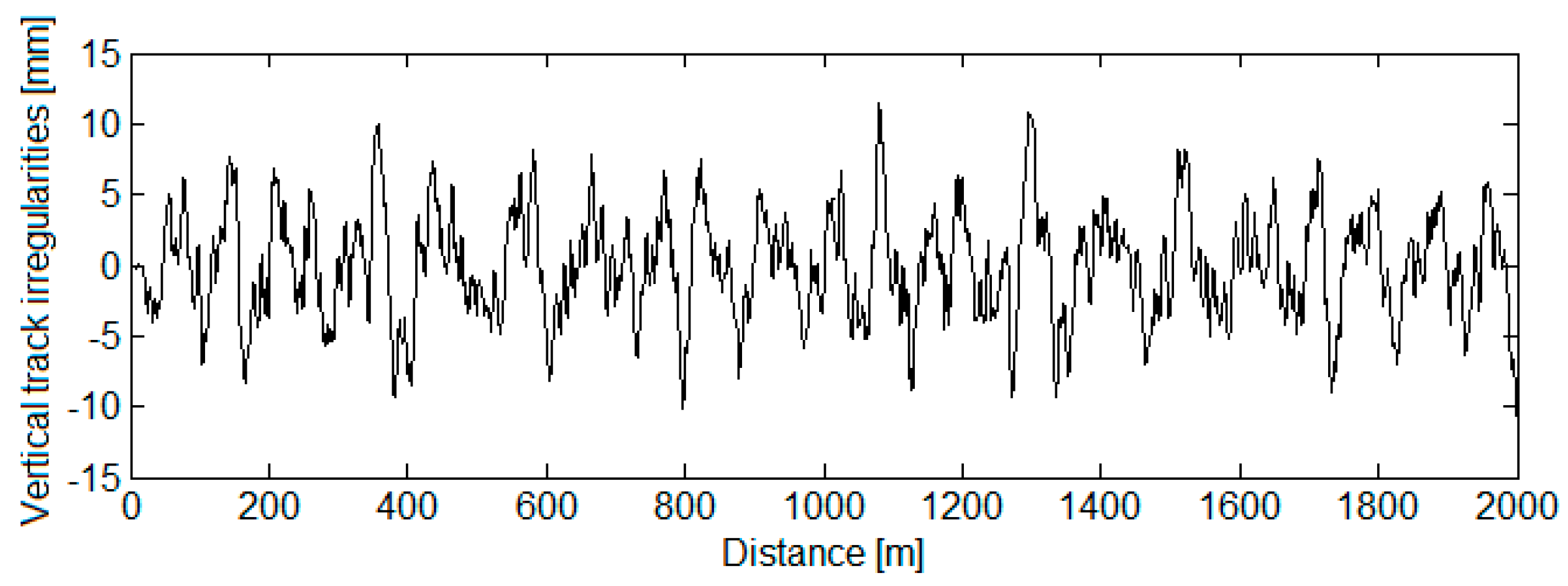
3.2. The Analytical Description of the Vertical Track Irregularities

The track irregularities are the primary input into the simulation applications for the dynamic behaviour of the bogie. To include the vertical track irregularities in the numerical model of the bogie-track system, they are synthesized following a method developed based on the power spectral density, defined as per ORE B176 [22] and the specifications in the UIC 518 [23] Leaflet concerning the geometric quality of the track, namely the magnitude of the standard deviations of the vertical track irregularities.
The power spectral density of the vertical track irregularities is written as:
Φ ( Ω p ) = A Q N 1 , 2 Ω c 2 ( Ω p 2 + Ω r 2 ) ( Ω p 2 + Ω c 2 )
where Ωc = 0.8246 rad/m, Ωr = 0.0206 rad/m, and AQN1,2 is a constant depending on the track quality.
The track quality constant AQN1,2 is calculated in such a way that the standard deviation of the vertical track irregularities (σηQN1, QN2) due to the components with the wavelength between Λ1 = 3 m and Λ2 = 25 m should comply with the specifications of the UIC 518 Leaflet, a function of the track quality index, QN1 or QN2 (see Figure 3):
A Q N 1 , 2 = 2 π σ η QN 1 , QN 2 2 Ω c 2 I 0
with
I 0 = Ω 2 Ω 1 d Ω p ( Ω p 2 + Ω r 2 ) ( Ω p 2 + Ω c 2 ) ,   for   Ω 1 , 2 = 2 π / Λ 1 , 2 .  
Figure 4 features the values of AQN1,2 calculated as per Equation (40), where σηQN1,2 has been assigned different values corresponding to a track of quality QN1 and a track of quality QN2, as per UIC 518 Leaflet (see Figure 3).
To synthesize the vertical track irregularities, the continuous spectrum of the power density Φ(Ωp) is changed into a discrete spectrum, with the amplitude of the spectral component‚ p’ in the form of
U p = 1 π Φ ( Ω p ) Δ Ω ,   cu   p = 0 ,   1 ,   2 ,     N ,  
where N + 1 is the number of spectral components, and Ωπ = Ω0 + kΔΩ, for p = 0, 1, 2, … N,
The partition of the wavenumber ΔΩ = Ω0 − ΩΝ is selected within the interval of the wavelengths of the track irregularities, included between the minimum wavelength Λmin and the maximum wavelength Λmax, so that,
Ω 0 = 2 π Λ max ,   Ω N = 2 π Λ min .
In agreement with the method herein, the vertical track irregularities are described via a pseudorandom function as in [24,25],
η j ( x j ) = f ( x j ) p = 0 N U p cos ( Ω p x j + φ p ) ,   for   x j   >   0 ,  
where xj, with j = 1, 2, depending on the wheelset position,
x 1 = x ;   x 2 = x 2 a b ,
for x = Vt, where V is the vehicle velocity.
Function f(xj) is a smoothing function applied to the distance L0, in the form of
f ( x j ) = [ 6 ( x j L 0 ) 5 15 ( x j L 0 ) 4 + 10 ( x j L 0 ) 3 ] H ( L 0 x j ) + H ( x j L 0 ) ,  
where H(.) is Heaviside step function.
To provide the vertical track irregularities with a random nature, the phase shift φp of the spectral component‚ p’ will be selected, for a uniform random distribution with values between–π and +π.
A track of QN1 quality is considered to synthesize the vertical track irregularities, for the velocity range of 120–160 km/h. In this case, as seen in Figure 3, the standard deviations of the vertical track irregularities have the following values: σηQN1 = 1.4 mm; σηQN2 = 1.7 mm. The vertical track irregularities are synthesized on a 2 km distance, upon considering the contribution of 300 spectral components, with wavelengths between Λmin = 3 m and Λmax = 120 m (see Figure 5). For the limit values of the interval of wavelengths, the minimum excitation frequency due to the track irregularities is 0.27 Hz, for velocity of 120 km/h, whereas the maximum frequency is 11.11 Hz. At the velocity of 160 km/h, the minimum excitation frequency due to the track irregularities is 0.37 Hz, whereas the maximum is 14.81 Hz. These frequency intervals fully cover the range of the eigenfunctions for the bogie frequencies.
Figure 6 shows an example for the time evolution of the acceleration in the reference points of the bogie with symmetrical damping, at the maximum velocity of 140 km/h. In the bogie reference points located against the suspension of the wheels in the front wheelset, acceleration reaches the maximum value of 5.63 m/s2, whereas for the rear wheelset, the value is 6.71 m/s2. In the reference point B, the maximum acceleration is 2.11 m/s2. In statistical terms, the values of RMS accelerations are representative, namely 1.46 m/s2—against points B11 and B12, 1.79 m/s2—against the points B21 and B22, and 0.77 m/s2—against point B. Such results show that the level of bogie vibrations against the suspension is almost two times bigger than against the bogie center.

3.3. The Results of the Numerical Simulations and Discussions

This section features the results of the numerical simulations, based on which the influence of interference of the bounce and pitch vertical vibrations with the roll horizontal vibrations generated by the suspension asymmetry upon the dynamic behaviour of the bogie is examined. The dynamic behaviour of the bogie is evaluated as per the values of RMS acceleration in the five reference points of the bogie.
A first analysis focuses on the influence of velocity upon the behaviour of vibrations in the bogie with symmetrical damping of the suspension. Figure 7 features the values of RMS acceleration in all five reference points of the bogie, for velocities ranging from 20 km/h to 140 km/h. The results in diagram (a) highlight that the level of vibrations rises along with the velocity in all bogie reference points, yet this rise is not continuous due to the geometric filtering effect given by the bogie wheelbase. It is also observed that, for any velocity, the vibration level is higher in the reference points located against the suspension and lower in the reference point located in the bogie center. Consequently, B11 and B12, and B21 and B22, respectively, can be considered as critical points of the regime of vibrations in the bogie. According to diagram (b), the critical points of the regime of vibrations in the bogie are velocity dependent. For the range of 40 km/h … 105 km/h, the critical points are B11 and B12, whereas B21 and B22 become critical points of the regime of vibrations in the bogie, outside the above speed interval.
It should also be noted the asymmetry of the bogie vibration regime in the reference points B11B21, respectively B21B22, where all the symmetry requirements—geometric, inertial, elastic, and damping—are being met.
The observations regarding increasing the vibration level with the velocity and the asymmetry of the bogie vibration behaviour of the reference points located on one side of the bogie frame, against the support points on the suspension, are in agreement with the experimental results performed on a passenger’s vehicle featured with Minden–Deutz-type bogies [26,27]. Moreover, the RMS accelerations obtained through numerical simulations are comparable to the RMS accelerations obtained experimentally.
The asymmetry of the suspension damping of the bogie can be simulated through the reduction in the damping constant in the suspension corresponding to one of the wheels, compared to the reference value cb (see Table 1). Four cases of reducing the damping constant of the suspension are considered, as seen in Table 2. Each of these cases corresponds to the reduction in the damping constant of the suspension of one of the four wheels by 20%, 40%, 60%, 80%, and 100%.
The reduction in the damping constant of the suspension of any of the wheels leads to a reduction in the damping ratio of the bogie suspension, defined as below:
ζ = c b 11 + c b 12 + c b 21 + c b 22 2 4 k b m b .  
For any of the four cases of reduction in the damping constant in Table 2, the values in Table 3 are obtained for the damping ratio of the suspension.
An initial evaluation of the influence of suspension asymmetry upon the dynamic behaviour of the bogie considers the reduction in the damping ratio of the suspension. According to the RMS acceleration values calculated at a velocity of 140 km/h, as in Figure 8, the reduction in the damping ratio of the suspension results in an increase in the level of vibrations in all the reference points of the bogie. For instance, a rise of 12.3% of RMS acceleration in the reference points B11 and B12 and of 14.4% for the RMS acceleration in the reference points in B21 and B22 can be noticed, should extreme values of the RMS acceleration be taken as reference, namely the ones corresponding to the limit values of the damping coefficient (ζband 0.75ζb). In the reference point B, the RMS acceleration increases by 13.5%.
It should be noted that the results in Figure 8 show that the level of vibrations in the bogie is symmetrical in the reference points located against the suspensions corresponding to the wheels of the same wheelsets, irrespective of the reduction in the damping ratio of the suspension. These results are nevertheless obtained when having considered the global decrease in the damping ratio of the suspension, disregarding the asymmetry of the suspension damping. A more accurate approach of this issue implies taking into account the asymmetry of the suspension damping introduced by the reduction in the damping constant in the suspension of one of the bogie wheels.
The diagrams in Figure 9 include the values of the RMS acceleration in the bogie reference points located against the suspensions of the four wheels for the cases of reduction in the damping constant in Table 2. Unlike the results presented previously (see Figure 8), it is observed that the asymmetry of the suspension damping determines the asymmetry of the vibration regime of the bogie in the reference points located against the suspensions corresponding to the wheels of the same wheelsets. This asymmetry is all the more pronounced as the degree of reduction in the damping constant increases.
Another interesting aspect can be also noticed, which is that the increase in the RMS accelerations is more or less significant, depending on the position of the suspension for which the damping constant is reduced and on the reduction degree of the damping constant. The highest increase in the RMS acceleration is recorded in the bogie reference point located against the suspension for which the damping constant is reduced, yet an important increment in the RMS acceleration can be also seen in the diagonally opposite reference point. For example, the increase in the acceleration can reach up to 29.8% in point B11, 20.9% in point B12, 10.6% in point B21, and 24.6% in point B22 when the damping constant of the wheel suspension is reduced (diagram a). Under such conditions, the critical point of the regime of vibrations of the bogie is the reference point against the suspension for which the damping constant is decreased.
Figure 10 features the values of the RMS accelerations at the velocity of 140 km/h in the reference point B of the bogie, for all four cases of reduction in the damping constant. In this case, the reduction in the damping constant in any of the suspension of wheels of the same wheelset is noticed to have the same affect upon the increase in the RMS acceleration in the bogie center. In contrast, the increase ratio of the RMS acceleration depends on the position of the suspension in the axle for which the damping constant is reduced. For instance, in the case herein, the acceleration increase can reach up to 12.7% when the damping constant is reduced in the suspension of wheels 11 or 12, and up to 31.6% for the wheels 21 or 22.

4. Conclusions

The paper analyzes the influence of interference of the vertical bounce and pitch vibrations with the roll horizontal vibrations generated by the suspension asymmetry upon the dynamic behaviour of a two-axle bogie. The dynamic behaviour of the bogie is evaluated based on the results from the numerical simulations concerning the RMS acceleration in five reference points of the regime of the vibrations of the bogie. The numerical simulation applications have been developed on the basis of two original bogie-track system models, which include the bogie with a symmetrical damping of the suspension model and the bogie with asymmetrical damping of the suspension model.
The basic characteristics of the regime of vibrations in the bogie, velocity-dependent, have been analyzed using the bogie with a symmetrical damping-track model. An important feature of the regime of vertical vibrations of the bogie has been pointed out, namely the geometric filtering effect generated by the bogie wheelbase, due to which the level of vibrations in the bogie does not increase continuously with velocity. Characteristic of the vertical vibration regime of the bogie is also the fact that, regardless of the velocity, the vibration level in the reference points located against the suspension is higher than the vibration level in the reference point in the bogie center. As a consequence, the reference points against the suspension can be considered to be critical points of the regime of vibrations of the bogie. The position of the critical point of the bogie vibration regime is influenced by the velocity, however. The asymmetry of the regime of vibrations in the reference points where all the symmetry requirements—geometric, inertial, elastic, and damping—are being met is another important characteristic highlighted.
The asymmetry of the suspension damping is simulated via the reduction in the damping constant of the suspension in one of the four wheels, and the influence of the decrease in the damping constant of the suspension upon the dynamic behaviour of the bogie is investigated from the perspective of the reduction in the damping ratio of the bogie suspension and the suspension asymmetry as well. Although both analyses reveal an increase in the level of vibrations in all the bogie reference points when the damping constant is reduced, there are important differences between the results regarding the characteristics of the bogie vibration regime.
According to the analysis on the reduction in the damping ratio of the bogie suspension, here are the facts:
-
The regime of vibrations of the bogie is symmetrical in the reference points located against the suspensions corresponding to the wheels of the same wheelsets;
-
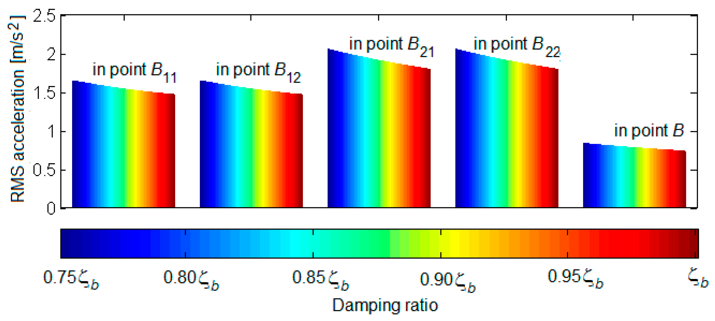
The vibration level of the bogie increases uniformly at all reference points;
-
In contrast, the results of the analysis considering the asymmetry of the suspension damping show the following:
-
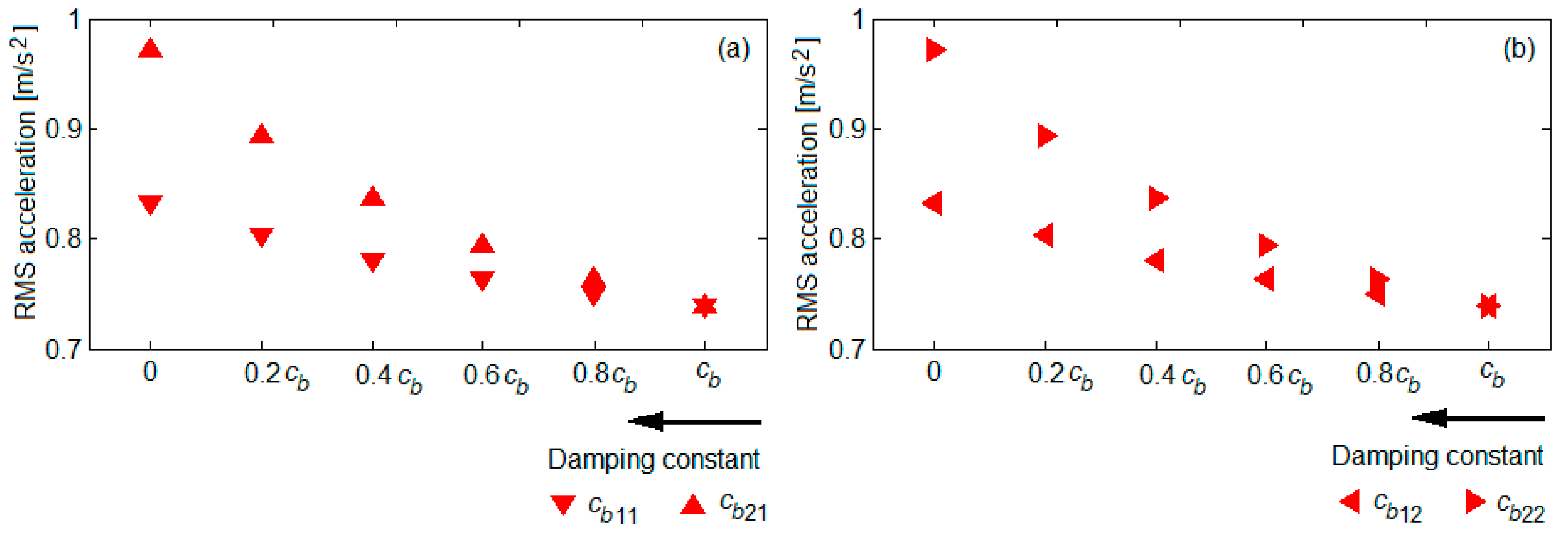
The regime of vibrations of the bogie is asymmetrical in the reference points located against the suspensions corresponding to the wheels of the same wheelset; the asymmetry is all the more pronounced as the degree of reduction in the damping constant increases;
-
The increase in the level of vibrations is more or less significant, depending on the position of the suspension for which the damping constant is reduced and on the reduction degree of the damping constant; the highest rise in the level of vibrations is recorded in the bogie reference point against the suspension for which the damping constant is decreased and in the diagonally opposite reference point.
The last conclusions can form the basis of the development of a method for monitoring and detecting the operational status of the dampers of the primary suspension of the railway vehicle, with the following advantages:
-
It is based on the analysis of the bogie dynamic behaviour, expressed in the form of RMS acceleration, and the RMS acceleration is a parameter representative in statistical terms, which can be easily measured and then compared to a reference value;
-
The failure of any of the four dampers of the primary suspension can be detected, based on the RMS accelerations measured in only two reference points of the bogie frame.

Author Contributions

Conceptual approach, M.D.; methodology, M.D.; software, M.D. and I.I.A.; validation, M.D.; formal analysis, M.D. and I.I.A.; writing—original draft, M.D.; writing—review and editing, M.D. and I.I.A. All authors have read and agreed to the published version of the manuscript.

Funding

This research received no external funding.

Conflicts of Interest

The author declares no conflict of interest.

References

  1. Jing, L.; Wang, K.; Zhai, W. Impact vibration behavior of railway vehicles: A state-of-the-art overview. Acta Mech. Sin. 2021, 37, 1193–1221. [Google Scholar] [CrossRef]
  2. Kouroussisa, G.; Connolly, D.P.; Verlinden, O. Railway-induced ground vibrations—A review of vehicle effects. Int. J. Rail Transp. 2014, 2, 69–110. [Google Scholar] [CrossRef]
  3. Iwnicki, S. Handbook of Railway Vehicle Dynamics; Taylor&Francis Group: Milton Park, UK, 2006. [Google Scholar]
  4. Melnik, R.; Koziak, S. Rail vehicle suspension condition monitoring—Approach and implementation. Int. J. Vibroeng. 2017, 19, 487–501. [Google Scholar] [CrossRef]
  5. Melnik, R.; Sowiński, B. The selection procedure of diagnostic indicator of suspension fault modes for the rail vehicles monitoring system. In Proceedings of the 7th European Workshop on Structural Health Monitoring, Nantes, France, 8–11 July 2014; pp. 126–132. [Google Scholar]
  6. Dumitriu, M. Effect of the asymmetry of suspension damping on the ride comfort of railway vehicles. Aust. J. Mech. Eng. 2020. [Google Scholar] [CrossRef]
  7. Dumitriu, M. Study on the effect of damping asymmetry of the vertical suspension on the railway bogie vibrations. Symmetry 2022, 14, 327. [Google Scholar] [CrossRef]
  8. Dumitriu, M. Fault detection of damper in railway vehicle suspension based on the cross-correlation analysis of bogie accelerations. Mech. Ind. 2019, 20, 102. [Google Scholar] [CrossRef]
  9. Mei, T.X.; Ding, X.J. New condition monitoring techniques for vehicle suspensions. In Proceedings of the 2008 4th IET International Conference on Railway Condition Monitoring, Derby, UK, 18–20 June 2008; pp. 1–6. [Google Scholar]
  10. Li, P.; Goodall, R.; Weston, P.; Ling, C.S.; Goodman, C. Estimation of railway vehicle suspension parameters for condition monitoring. Control. Eng. Pract. 2007, 15, 43–55. [Google Scholar] [CrossRef]
  11. Ngigi, R.W.; Pîslaru, C.; Ball, A.; Gu, F. Modern techniques for condition monitoring of railway vehicle dynamics. J. Phys. Conf. Ser. 2012, 364, 012016. [Google Scholar] [CrossRef]
  12. Alfi, S.; Bionda, S.; Bruni, S.; Gasparetto, L. Condition monitoring of suspension components in railway bogies. In Proceedings of the 5th IET Conference on Railway Condition Monitoring and Non-Destructive Testing (RCM 2011), Derby Conference Centre, UK, 29–30 November 2011; pp. 1–6. [Google Scholar]
  13. Bruni, S.; Goodall, R.; Mei, T.X.; Tsunashima, H. Control and monitoring for railway vehicle dynamics. Veh. Syst. Dyn. 2007, 45, 743–779. [Google Scholar] [CrossRef]
  14. Goodall, R.M.; Roberts, C. Concept and techniques for railway condition monitoring. In Proceedings of the 2006 IET International Conference On Railway Condition Monitoring, Birmingham, UK, 29–30 November 2006; pp. 90–95. [Google Scholar]
  15. Dumitriu, M. Condition monitoring of the dampers in the railway vehicle suspension based on the vibrations response analysis of the bogie. Sensors 2022, 22, 3290. [Google Scholar] [CrossRef] [PubMed]
  16. Dumitriu, M.; Leu, M. Study regarding the dynamic loads upon the track at failure of the dampers in the primary suspension of the railway vehicle. In Proceedings of the IOP Conference Series: Materials Science and Engineering, 2018, ModTech International Conference—Modern Technologies in Industrial Engineering, Constanţa, Romania, 13–16 June 2018; Volume 400, p. 042020. [Google Scholar]
  17. Dumitriu, M.; Gheţi, M.A. Evaluation of the vertical vibrations behaviour of the bogie at failure of the dampers in the primary suspension of the railway vehicle. In Proceedings of the 22nd International Conference on Innovative Manufacturing Engineering and Energy—IManE&E 2018, Chisinau, Republic of Moldova, 31 May–2 June 2018; Volume 178, p. 06001. [Google Scholar]
  18. Dumitriu, M.; Gheţi, M.A. Numerical study on the influence of primary suspension damping upon the dynamic behaviour of railway vehicles. In Proceedings of the IOP Conference Series: Materials Science and Engineering, the 8th International Conference on Advanced Concepts in Mechanical Engineering—ACME 2018, Iasi, Romania, 13–16 June 2018; Volume 444, p. 042001. [Google Scholar]
  19. Fernandes, J.C.M.; Gonçalves, P.J.P.; Silveira, M. Interaction between asymmetrical damping and geometrical nonlinearity in vehicle suspension systems improves comfort. Nonlinear Dyn. 2020, 99, 1561–1576. [Google Scholar] [CrossRef]
  20. Dumitriu, M.; Stănică, D.I. Influence of the primary suspension damping on the ride comfort in the railway vehicles. Mater. Sci. Forum 2019, 957, 53–62. [Google Scholar] [CrossRef]
  21. Dumitriu, M.; Gheţi, M.A. Influence of the interference of bounce and pitch vibrations upon the dynamic behaviour in the bogie of a railway vehicle. In Proceedings of the IOP Conference Series: Materials Science and Engineering, 2018, ModTech International Conference—Modern Technologies in Industrial Engineering, Constanţa, Romania, 13–16 June 2018; Volume 400, p. 042020. [Google Scholar]
  22. C 116. Interaction between Vehicles and Track, RP 1, Power Spectral Density of Track Irregularities, Part 1: Definitions, Conventions and Available Data; UIC: Utrecht, The Netherlands, 1971. [Google Scholar]
  23. UIC 518. Testing and Approval of Railway Vehicles from the Point of View of Their Dynamic Behaviour–Safety–Track Fatigue–Running Behaviour, 4th ed.; International Union of Railways: Paris, France, 2009. [Google Scholar]
  24. Dumitriu, M. Method to synthesize the track vertical irregularities. Sci. Bull. Petru Maior Univ. Targu Mures 2014, 11, 17–24. [Google Scholar]
  25. Dumitriu, M.; Răcănel, I.R. Experimental verification of method to synthesize the track vertical irregularities. Rom. J. Transp. Infrastruct. 2018, 7, 40–60. [Google Scholar] [CrossRef]
  26. Dumitriu, M.; Cruceanu, I.C. Experimental analysis of vertical vibrations of a railway bogie. Commun. Sci. Lett. Univ. Zilina. 2021, 23, 299–307. [Google Scholar] [CrossRef]
  27. Dumitriu, M.; Cruceanu, I.C.; Fologea, D. Experimental study of the bogie vertical vibration—Correlation between bogie frame accelerations and wheelsets accelerations. UPB Sci. Bull. Ser. D Mech. Eng. 2021, 83, 83–94. [Google Scholar]
Figure 1. The model of the bogie with symmetrical damping of suspension—track.
Vibration 05 00039 g001
Figure 2. The model of the bogie with asymmetrical damping of suspension—track.
Vibration 05 00039 g002
Figure 3. Standard deviations for vertical track irregularities.
Vibration 05 00039 g003
Figure 4. The quality constant of the track.
Vibration 05 00039 g004
Figure 5. Synthesis of the vertical track irregularities.
Vibration 05 00039 g005
Figure 6. Accelerations in the bogie reference points at velocity of 140 km/h (a,b).
Vibration 05 00039 g006
Figure 7. RMS acceleration in the bogie reference points: (a) velocity influence upon RMS acceleration; (b) velocity influence upon the critical point of the regime of vibrations of the bogie.
Vibration 05 00039 g007
Figure 8. Influence the reduction in the damping ratio of suspension upon the RMS acceleration at a velocity of 140 km/h.
Vibration 05 00039 g008
Figure 9. Influence the reduction in the damping constant of the suspension upon RMS acceleration at a velocity of 140 km/h: (a) reduction in the damping constant of the suspension of the wheel 11; (b) reduction in the damping constant of the suspension of the wheel 12; (c) reduction in the damping constant of the suspension of the wheel 21; (d) reduction in the damping constant of the suspension of the wheel 22.
Vibration 05 00039 g009
Figure 10. Influence the reduction the damping constant of the suspension upon RMS acceleration in point B, at a velocity of 140 km/h: (a) reduction in the damping constant of the suspension in wheels 11 or 12; (b) reduction in the damping constant of the suspension in wheels 21 or 22.
Vibration 05 00039 g010
Table 1. Reference parameters of the bogie-track system numerical model.
Bogie frame massmb = 2700 kg
Wheelset massmw = 1400 kg
Track mass mr = 175 kg
Bogie wheelbase2ab = 2.5 m
Lateral base of the suspension2b = 2 m
Semi-distance between the wheel-rail contact points2e = 1.5 m
Bogie pitch inertia momentJbθ = 1.728·103 kg·m2
Bogie roll inertia momentJbφ = 1.323·103 kg·m2
Elastic constant of the primary suspension per wheelkb = 0.616 MN/m
Damping constant of the primary suspension per wheel—Reference valuecb = 9.05 kNs/m
Elastic constant of the track kr = 70 MN/m
Damping constant of the track cr = 60 kNs/m
Stiffness of the wheel-rail contactkH = 1500 MN/m
Table 2. Cases of reduction in the damping constant.
Case ICase II
cb0.8cb0.6cb0.4cb0.2cb0 cb0.8cb0.6cb0.4cb0.2cb0
cb11 cb11
cb12 cb12
cb21 cb21
cb22 cb22
Case IIICase IV
cb0.8cb0.6cb0.4cb0.2cb0 cb0.8cb0.6cb0.4cb0.2cb0
cb11 cb11
cb12 cb12
cb21 cb21
cb22 cb22
Table 3. The values of the damping ratio of the suspension when reducing the damping constant of the suspension of one of the wheels.
cbjk, for j = 1, 2 and k = 1, 2cb0.8cb0.6cb0.4cb0.2cb0
ζbζb0.95ζb0.90ζb0.85ζb0.80ζb0.75ζb
Publisher’s Note: MDPI stays neutral with regard to jurisdictional claims in published maps and institutional affiliations.

