

Vibration Analysis of a 5-DOF Long-Reach Robotic Arm


Abstract
:1. Introduction
1.1. Motivation and Background
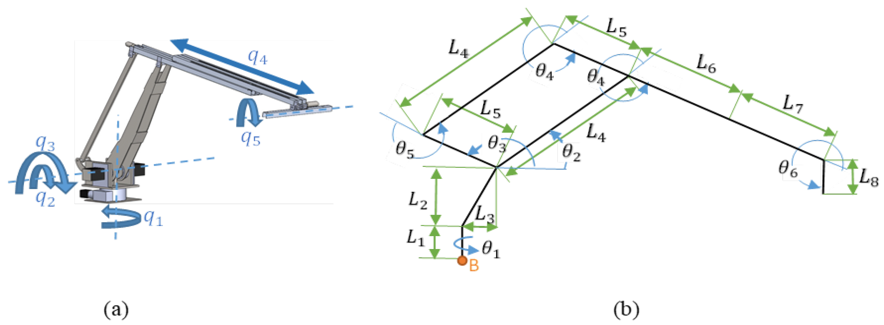
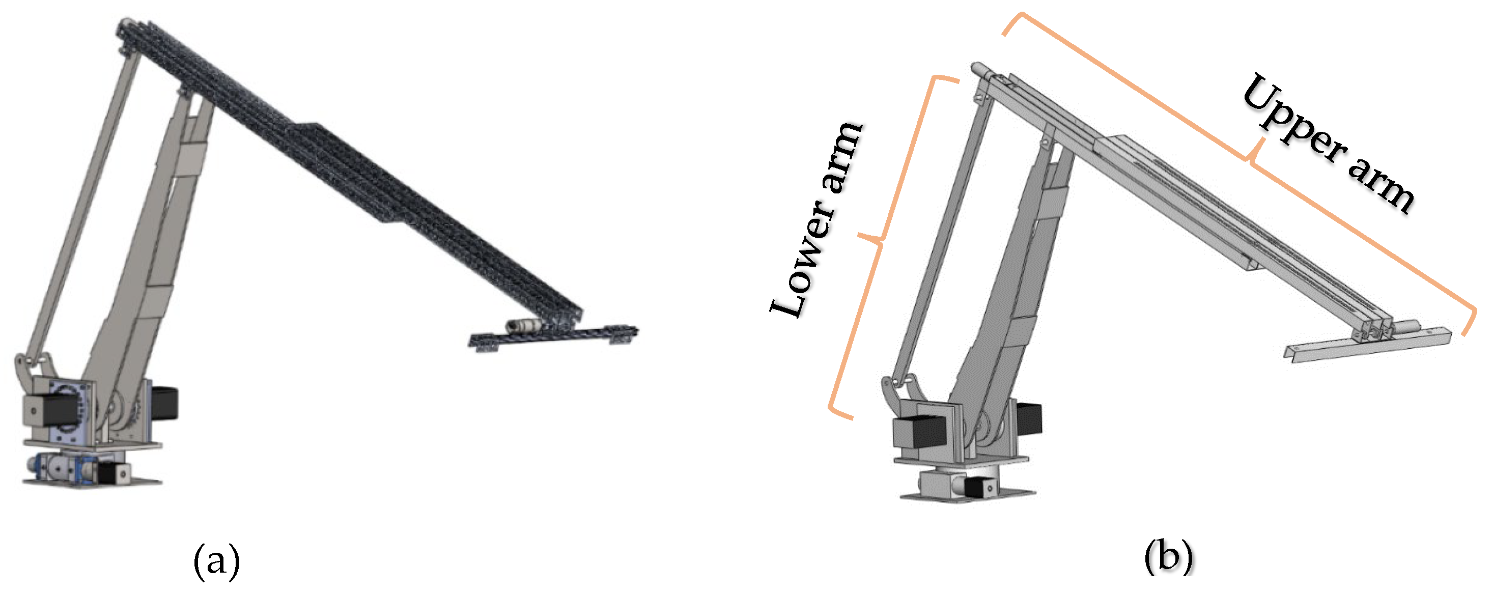
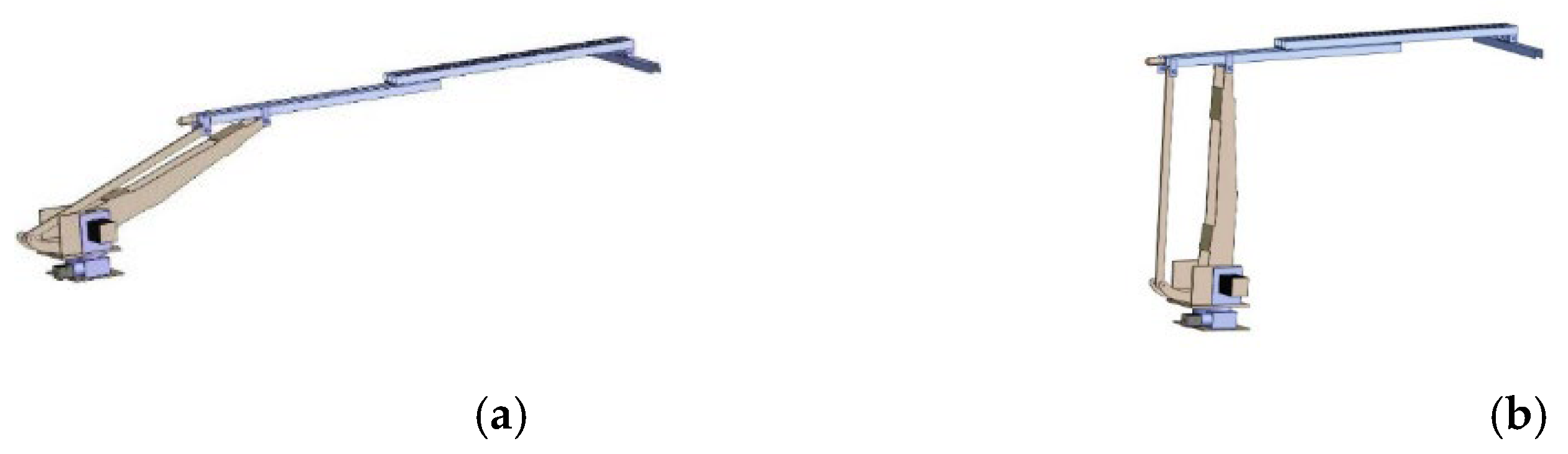
1.2. The Developed Manipulator
2. Finite Element Vibration Analysis
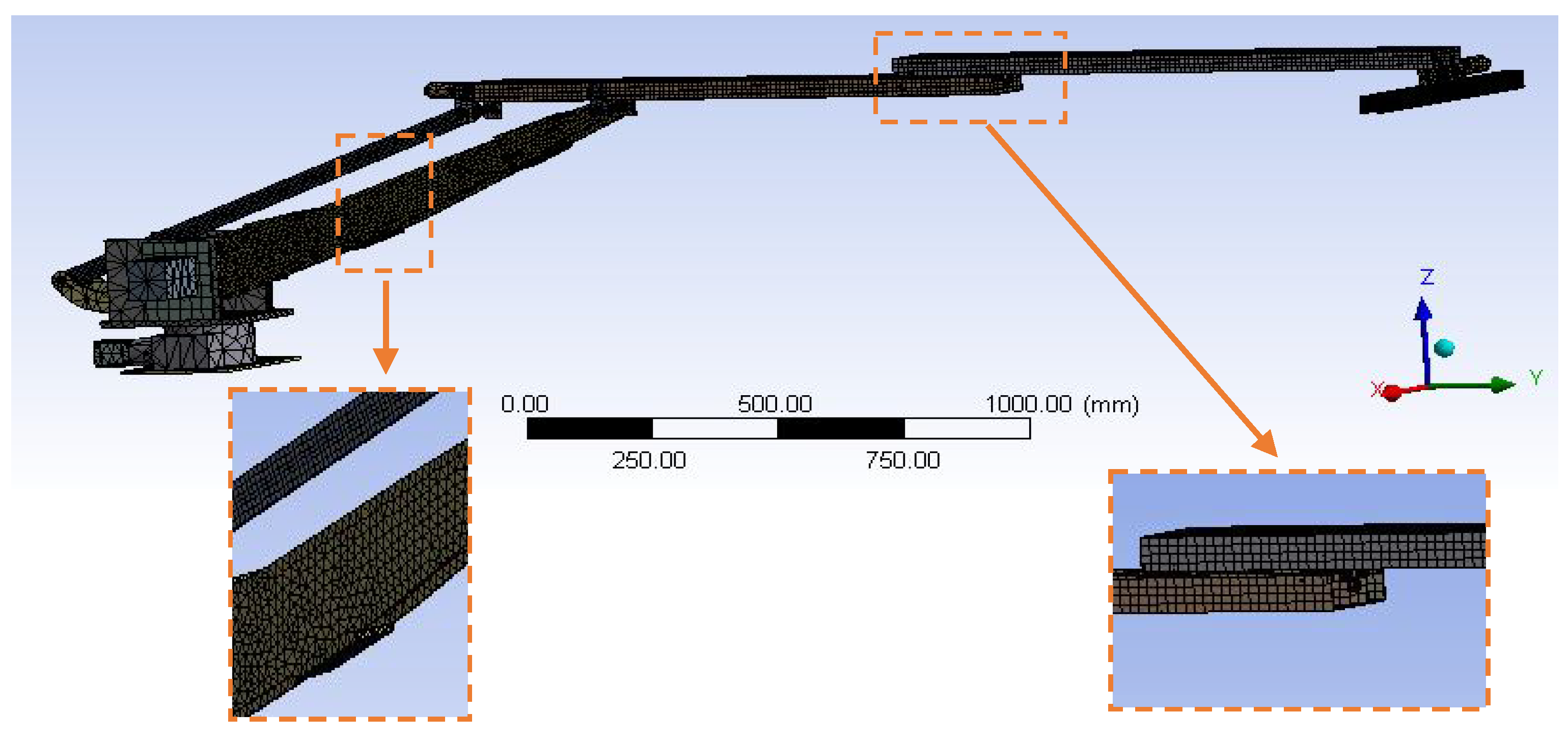
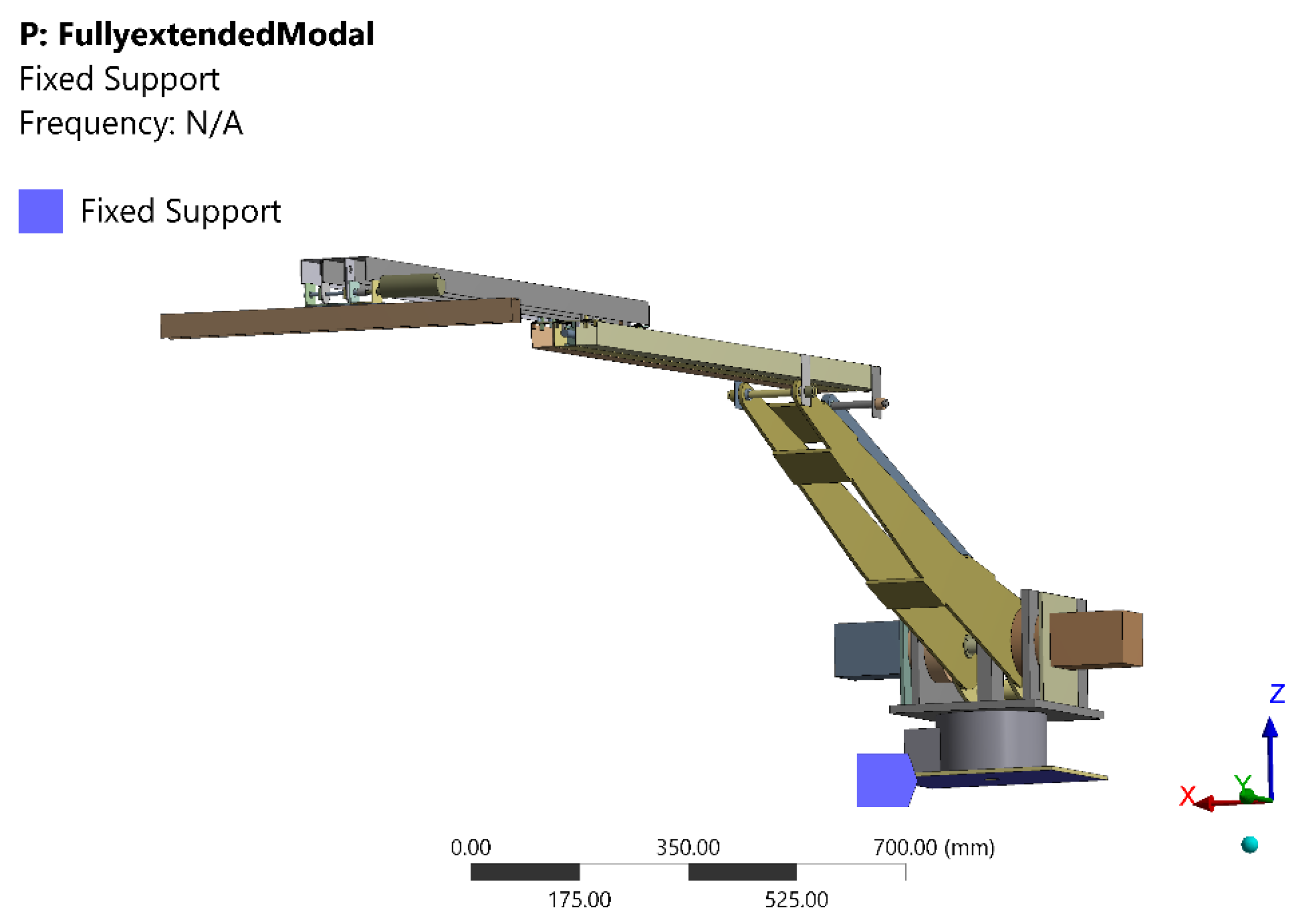
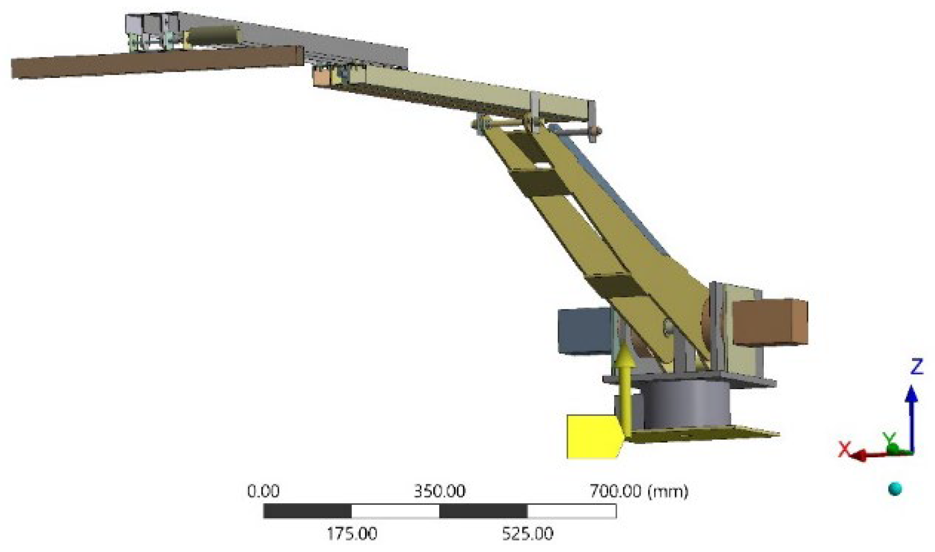
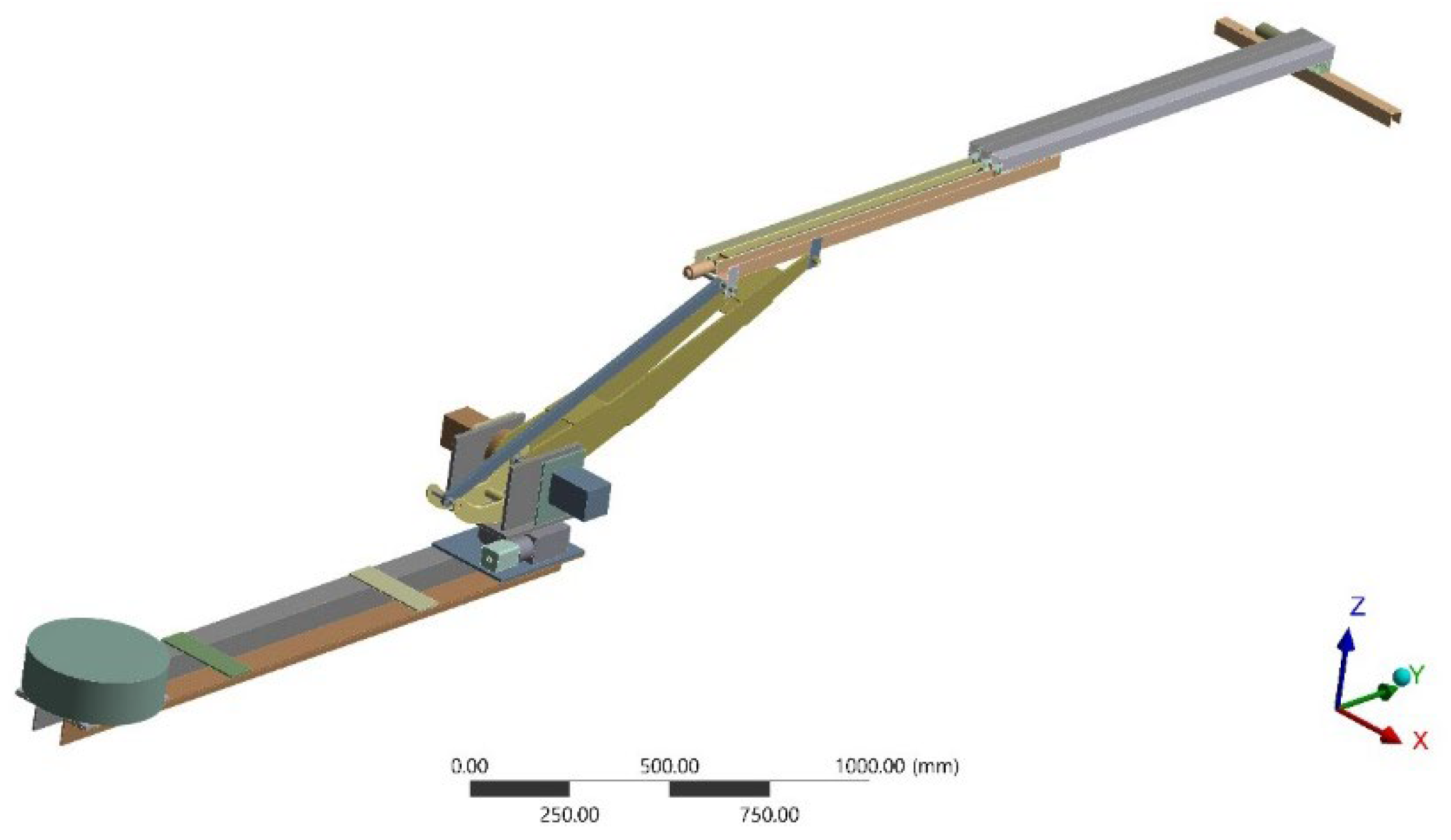
2.1. 3D Model of 5-DOF Robot Manipulator
- 1.
- To prevent meshing complications, most bolts, nuts and bearings were removed and some parts (motors, gear box and upper link) were replaced with similar simpler geometries having similar masses by removing tiny features such as fillets and screw threads, or removing holes and reducing the thickness of beams to compensate for the added mass.
- 2.
- Deflections are assumed to be small. This assumption is verified by finite element and experimentally; the manipulator’s tip deflection compared with its overall length are small based on Euler-Bernoulli beam theory.
- 3.
- The system is assumed to be linear for modal analysis. The vibration of the manipulator in the fully extended-configuration is similar to the vibration of a cantilever beam with small deflections. This means that the ratio of tip deflection over length of cantilever is less than 10%, and Euler-Bernoulli beam theory is valid in this case; superpositions can also be used for this system, as for linear systems.
2.2. Modal Analysis Process
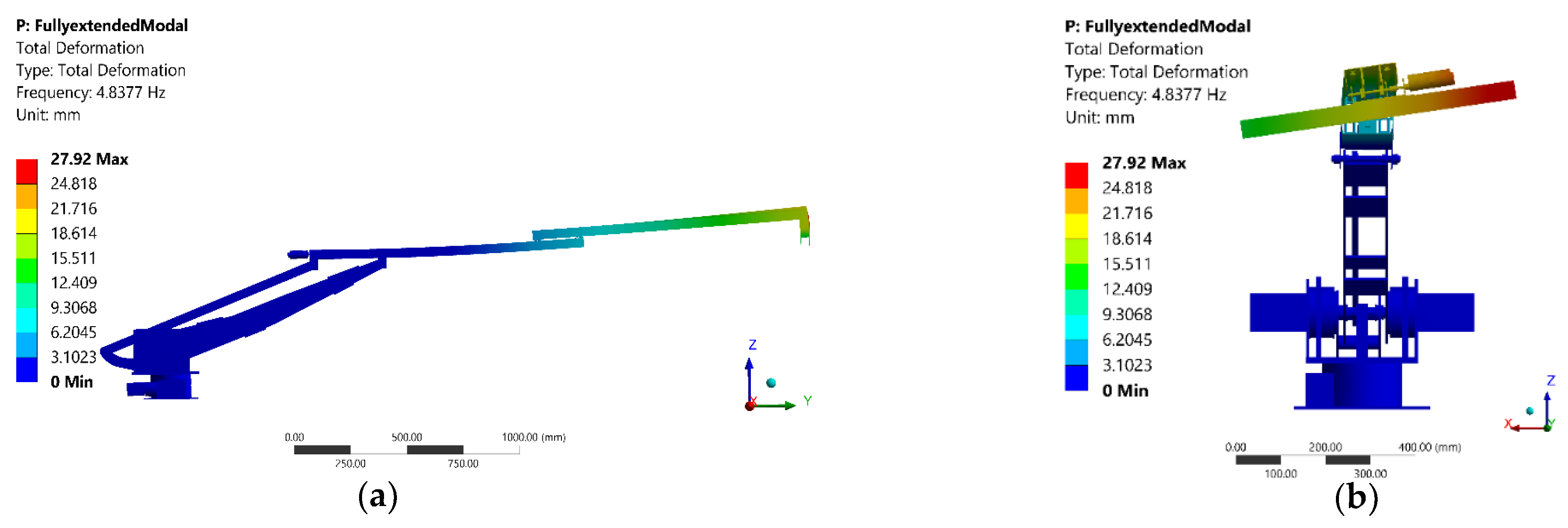
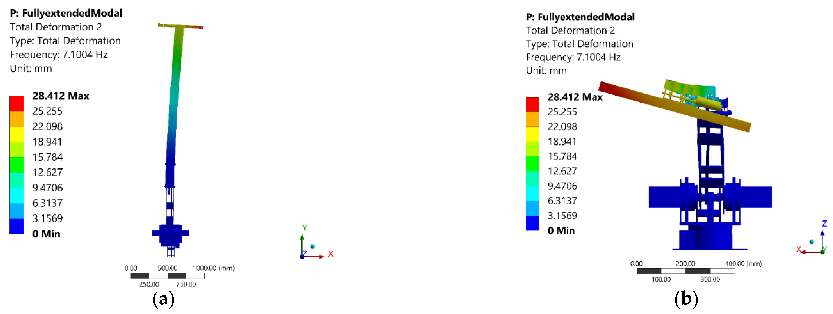
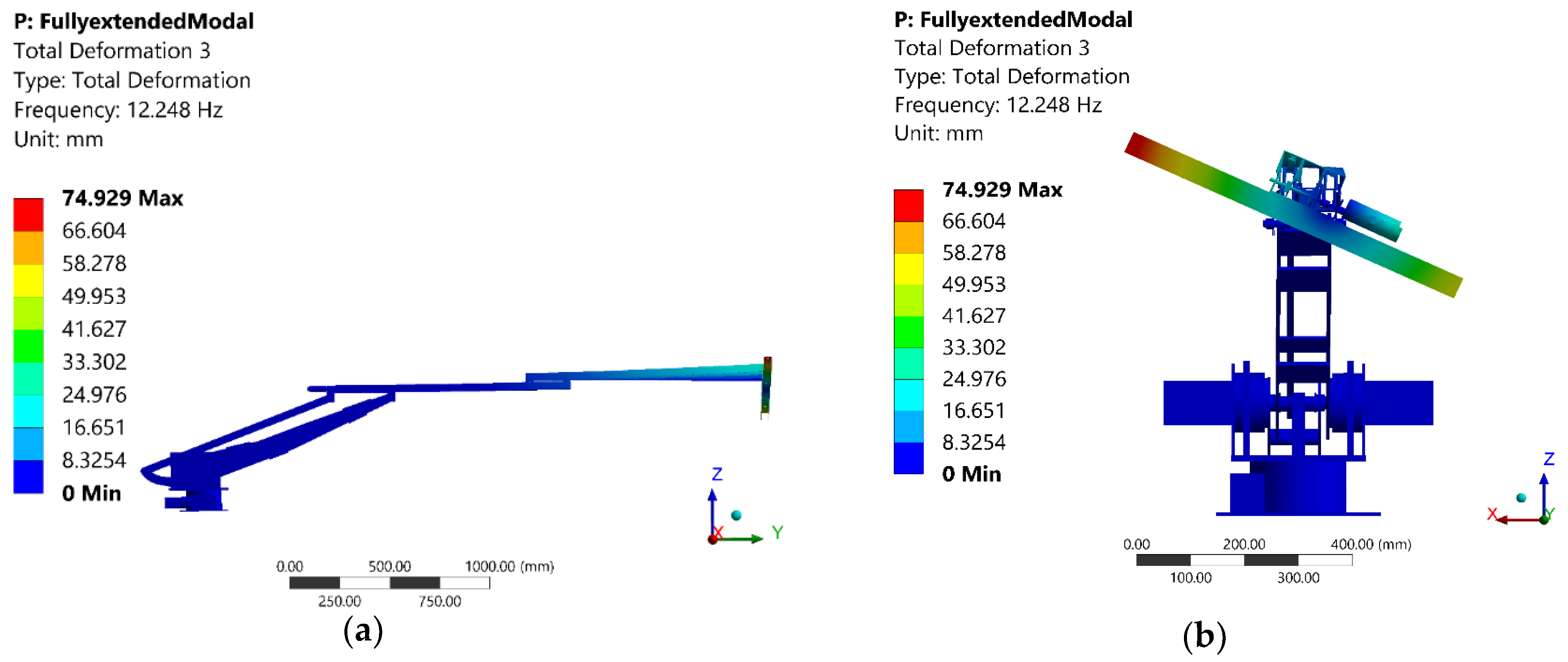
2.3. Modal Analysis Results
2.4. Harmonic (Force) Vibration Analysis Process
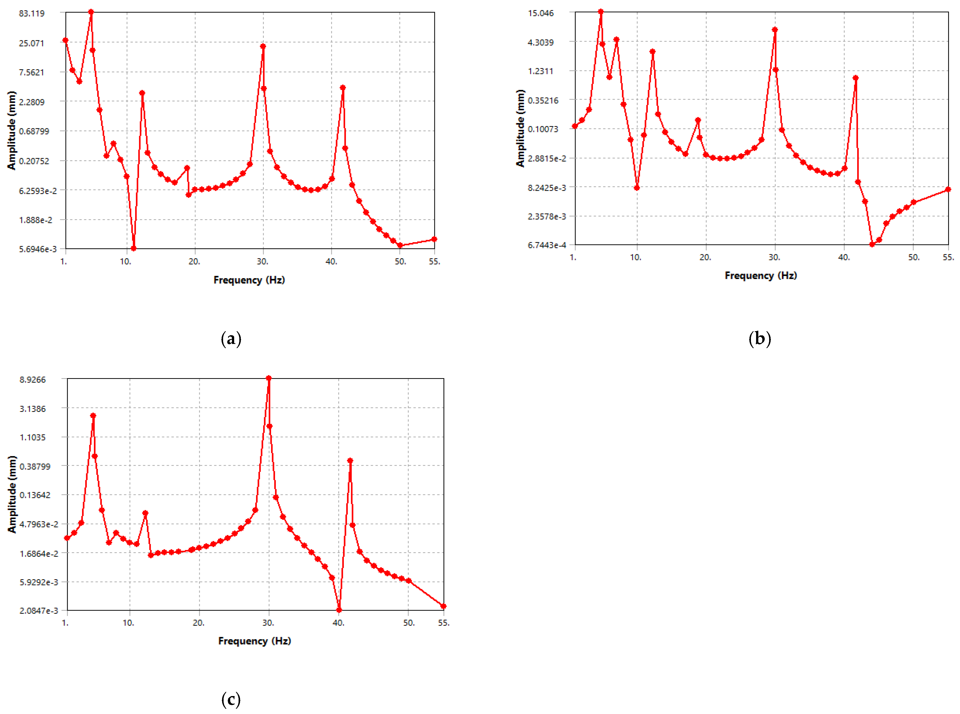
2.5. Harmonic (Force) Vibration Analysis Results
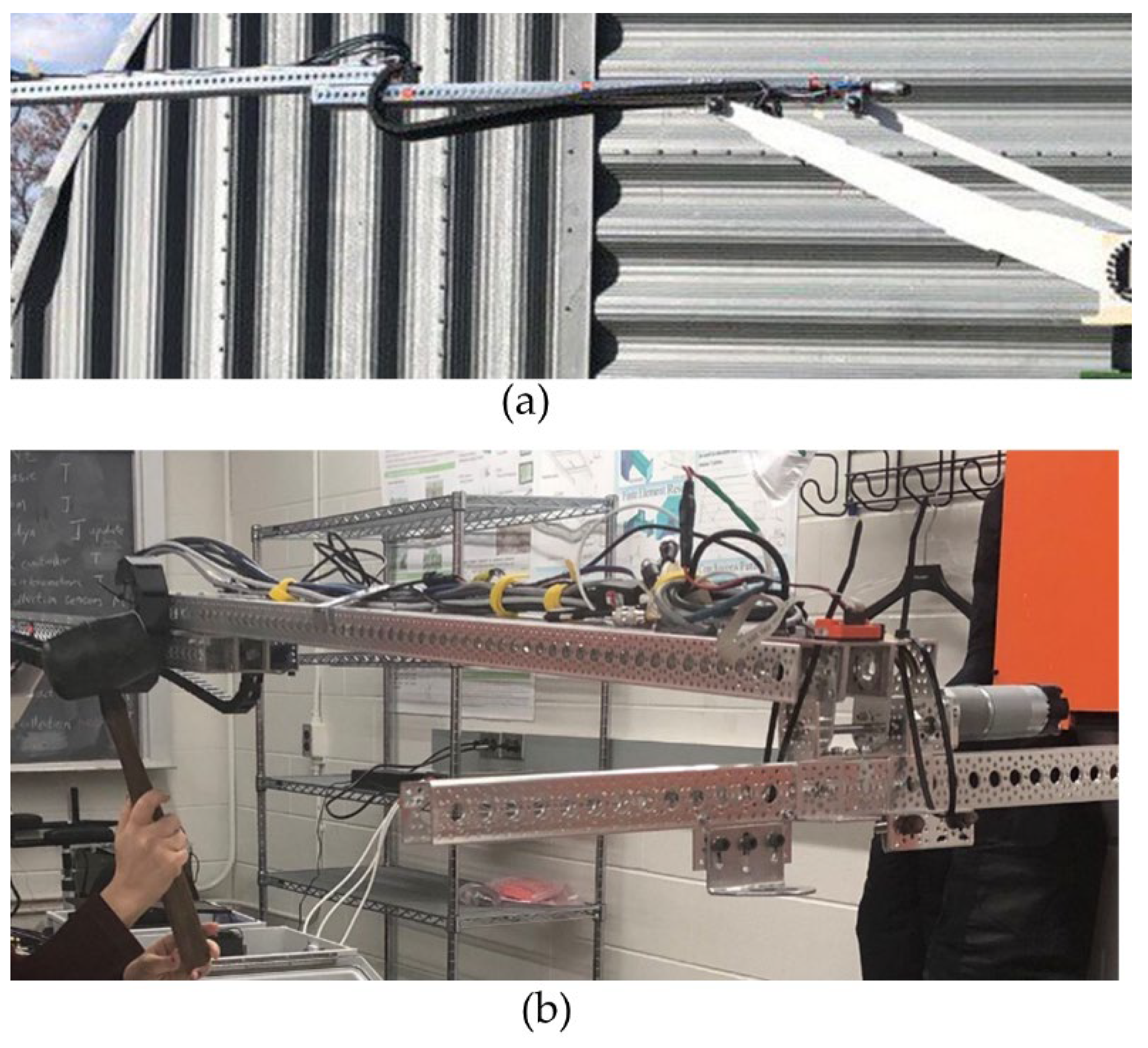
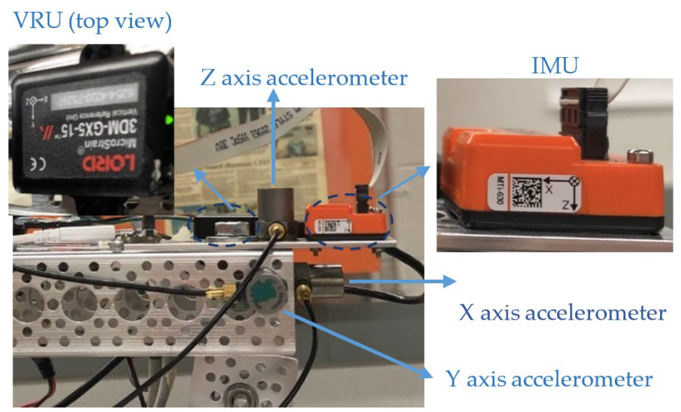
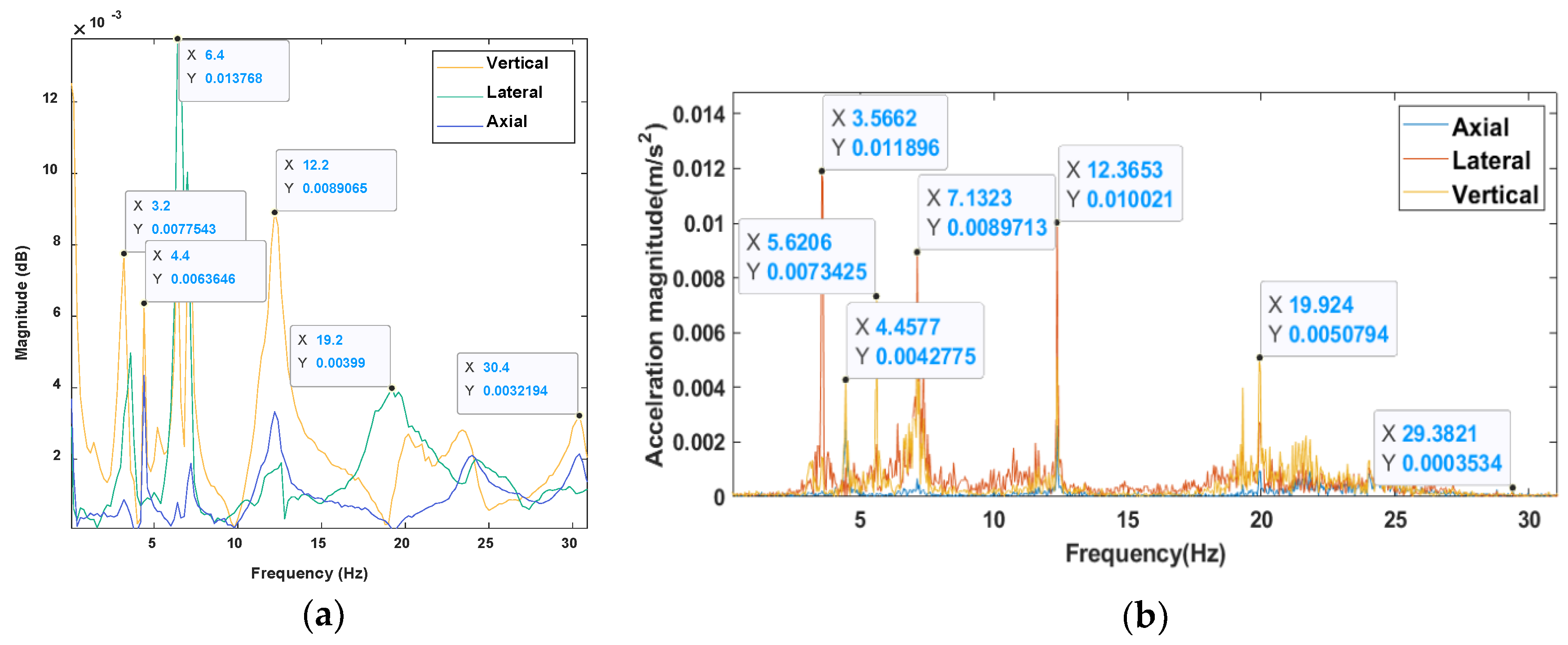
3. Experimental Modal Analysis and Results
4. Discussion
4.1. Comparison of Experimental and Finite Element Modal Analysis Results
4.2. Discussion of Mode Shapes and Effect of Different Configurations of the Manipulator on the Modal Analysis Results
4.3. Harmonic (Force) Response Discussion
5. Conclusions
Author Contributions
Funding
Acknowledgments
Conflicts of Interest
References
- Soto-Ocampo, C.R.; Mera, J.M.; Cano-Moreno, J.D.; Garcia-Bernardo, J.L. Low-Cost, High-Frequency, Data Acquisition System for Condition Monitoring of Rotating Machinery through Vibration Analysis-Case Study. Sensors 2020, 20, 3493. [Google Scholar] [CrossRef] [PubMed]
- Tang, Y.; Yu, Y.; Shi, J.; Zhang, S. Modal and harmonic response analysis of key components of robotic arm based on ANSYS. Vibroengineering Procedia 2016, 12, 109–114. [Google Scholar]
- Udameeshi, S.; Patil, G.S.; Patil, M.V. Finite element analysis of pick and place robotic structure. Int. Res. J. Eng. Technol. 2017, 3, 1497–1500. [Google Scholar]
- Sahu, S.; Choudhury, B.B.; Biswal, B.B. A vibration analysis of a 6 axis industrial robot using FEA. Mater. Today Proc. 2017, 4, 2403–2410. [Google Scholar] [CrossRef]
- Zhou, J.; Yang, Z.; Chen, S. Analysis of the harvesting robot arm modal based on CAE. J. Chem. Pharm. Res. 2014, 6, 669–673. [Google Scholar]
- Cheng, L.; Wang, H. Finite element modal analysis of the FPD glass substrates handling robot. In Proceedings of the 2012 IEEE International Conference on Mechatronics and Automation, Chengdu, China, 5–8 August 2012; IEEE: Piscataway, NJ, USA, 2012. paper no. 6284331. pp. 1341–1346. [Google Scholar]
- He, D.T.; Guo, Y. Finite element analysis of humanoid robot arm. In Proceedings of the 2016 13th International Conference on Ubiquitous Robots and Ambient Intelligence (URAI), Xi’an, China, 19–22 August 2016; IEEE: Piscataway, NJ, USA, 2016; pp. 772–776. [Google Scholar]
- Zhang, J.; Yuan, Z.; Yuan, W.; Dong, S. Lightweight Design and Modal Analysis of Calf Structure of Hydraulic Biped Robot. In Proceedings of the 2020 10th Institute of Electrical and Electronics Engineers International Conference on Cyber Technology in Automation, Control, and Intelligent Systems (CYBER), Xi’an, China, 10–13 October 2020; IEEE: Piscataway, NJ, USA, 2020; pp. 146–151. [Google Scholar]
- Vu, V.H.; Liu, Z.; Thomas, M.; Hazel, B. Modal analysis of a light-weight robot with a rotating tool installed at the end effector. Proc. Inst. Mech. Eng. Part C J. Mech. Eng. Sci. 2017, 231, 1664–1676. [Google Scholar] [CrossRef]
- Liu, Z.; Song, L.B.; Li, Y.; Pan, B.Z. Comparison of finite element and experimental modal analysis of multi-joint flexible robotic arm. In Proceedings of the 2017 International Conference on Mechanical, System and Control Engineering (ICMSC), St. Petersburg, Russia, 19–21 May 2017; IEEE: Piscataway, NJ, USA, 2017. paper no. 2021, 7959450. pp. 96–100. [Google Scholar]
- Tang, Z.; Pan, Y.; Cheng, Z. Vibration analysis and passive control of SCARA robot arm. In Proceedings of the 2019 International Conference on Robotics, Intelligent Control and Artificial Intelligence, Shanghai, China, 20–22 September 2019; Association for Computing Machinery: New York, NY, USA, 2019; pp. 89–93. [Google Scholar]
- Liao, X.; Gong, C.; Lin, Y.; Wang, W. The finite element modal analysis of the base of welding robot. In Proceedings of the 2010 3rd International Conference on Advanced Computer Theory and Engineering (ICACTE), Chendu, China, 20–22 August 2010; IEEE: Piscataway, NJ, USA, 2010; Volume 2, pp. 123–126. [Google Scholar]
- Biglari, H.; Golmohammadi, M.; Hayati, S.; Hemmati, S. Vibration reduction of a flexible robot link using a frictional damper. J. Vib. Control. 2021, 27, 985–997. [Google Scholar] [CrossRef]
- Faieghi, M.; Atashzar, S.F.; Sharma, M.; Tutunea-Fatan, O.R.; Eagleson, R.; Ferreira, L.M. Vibration analysis in robot-driven glenoid reaming procedure. In Proceedings of the 2020 IEEE/ASME International Conference on Advanced Intelligent Mechatronics (AIM), Boston, MA, USA, 6–9 July 2020; IEEE: Piscataway, NJ, USA, 2020; pp. 741–746. [Google Scholar]
- Berninger, T.F.; Fuderer, S.; Rixen, D.J. Modal analysis of a 7 DoF sweet pepper harvesting robot. In Proceedings of the 37th IMAC, A Conference and Exposition on Structural Dynamics, Orlando, FL, USA, 28–31 January 2019; Springer: Cham, Switzerland, 2019; Volume 8, pp. 163–170. [Google Scholar]
- Rafieian, F.; Liu, Z.; Hazel, B. Dynamic model and modal testing for vibration analysis of robotic grinding process with a 6DOF flexible-joint manipulator. In Proceedings of the 2009 International Conference on Mechatronics and Automation, Changchun, China, 9–12 August 2009; IEEE: Piscataway, NJ, USA; pp. 2793–2798. [Google Scholar]
- Fuentes, A.T.; Kipfmueller, M.; Prieto, M.J. 6 DOF articulated-arm robot and mobile platform: Dynamic modelling as Multibody System and its validation via Experimental Modal Analysis. In Proceedings of the IOP Conference Series: Materials Science and Engineering, 4th International Conference on Mechanical Engineering Research (ICMER2017), Lumut, Malaysia, 1–2 August 2017; IOP Publishing: Bristol, UK, 2017; Volume 257, p. 012008. [Google Scholar]
- Ariano, A.; Perna, V.; Senatore, A.; Scatigno, R.; Nicolò, F.; Fazioli, F.; Avallone, G.; Pesce, S.; Gagliano, A. Simulation and Experimental Validation of Novel Trajectory Planning Strategy to Reduce Vibrations and Improve Productivity of Robotic Manipulator. Electronics 2020, 9, 581. [Google Scholar] [CrossRef]
- Min, F.; Wang, G.; Liu, N. Collision detection and identification on robot manipulators based on vibration analysis. Sensors 2019, 19, 1080. [Google Scholar] [CrossRef] [PubMed]
- Bottin, M.; Cocuzza, S.; Comand, N.; Doria, A. Modeling and identification of an industrial robot with a selective modal approach. Appl. Sci. 2020, 10, 4619. [Google Scholar] [CrossRef]
- Nguyen-Van, S.; Gwak, K.W.; Nguyen, D.H.; Lee, S.G.; Kang, B.H. A novel modified analytical method and finite element method for vibration analysis of cable-driven parallel robots. J. Mech. Sci. Technol. 2020, 34, 3575–3586. [Google Scholar] [CrossRef]
- Ivanov, S.; Zudilova, T.; Ivanova, L.; Meleshkova, Z.; Voitiuk, T. Vibration Protection of the Robotic Arm from External Effects on the Base. In Proceedings of the 26th Conference of Open Innovations Association FRUCT, Yaroslavl, Russia, 20–24 April 2020; Volume 26, pp. 514–522, FRUCT Oy. [Google Scholar]
- Zhang, Q.; Fotouhi, R.; Cote, J.; KhakPour, M. Lightweight long-reach 5-dof robot arm for farm application. In Proceedings of the International Design Engineering Technical Conferences and Computers and Information in Engineering Conference, Anaheim, CA, USA, 18–21 August 2019. DETC2019-98366. [Google Scholar]
- Stolarski, T.; Nakasone, Y.; Yoshimoto, S. Engineering Analysis with ANSYS Software, 2nd ed.; Butterworth-Heinemann: Oxford, UK, 2018. [Google Scholar]


| Joint | Position Constraints |
|---|---|
| 1 | |
| 2 | |
| 3 | |
| 4 | 1 m |
| 5 |
| Mode | Frequency [Hz] |
|---|---|
| 1. | 4.83 |
| 2. | 7.10 |
| 3. | 12.25 |
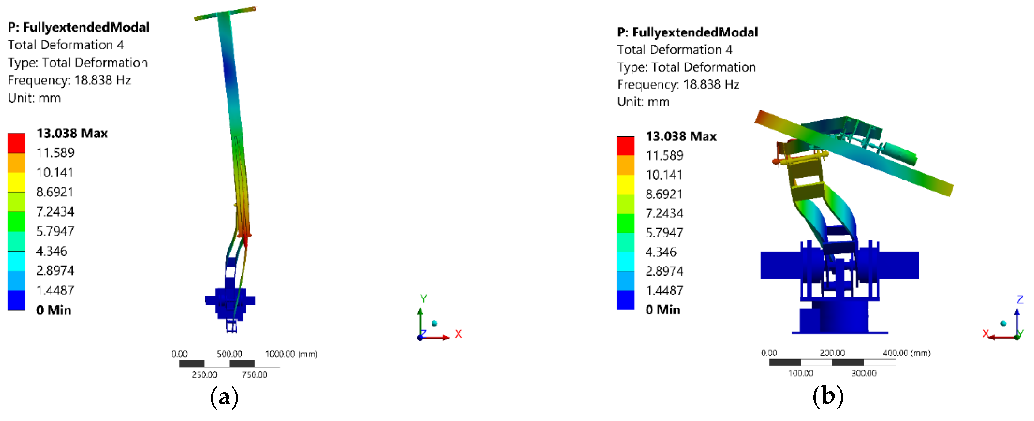
| 4. | 18.84 |
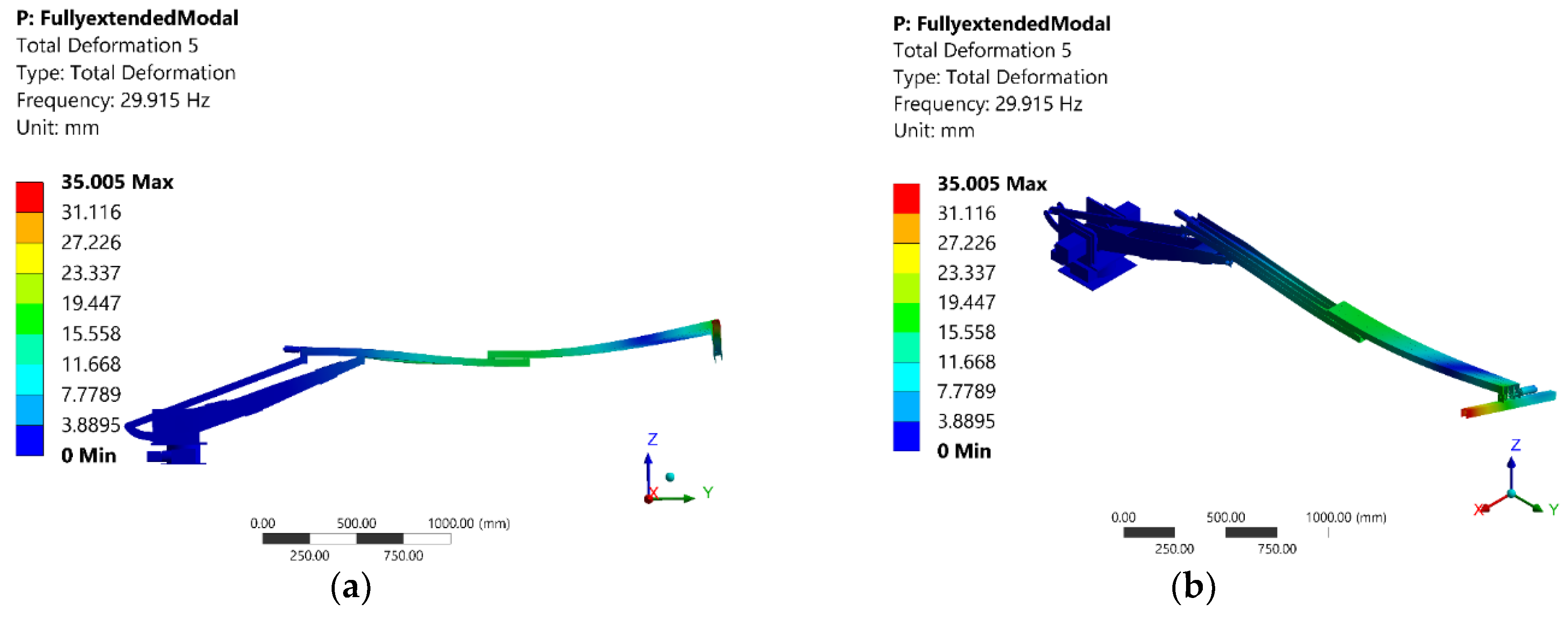
| 5. | 29.91 |
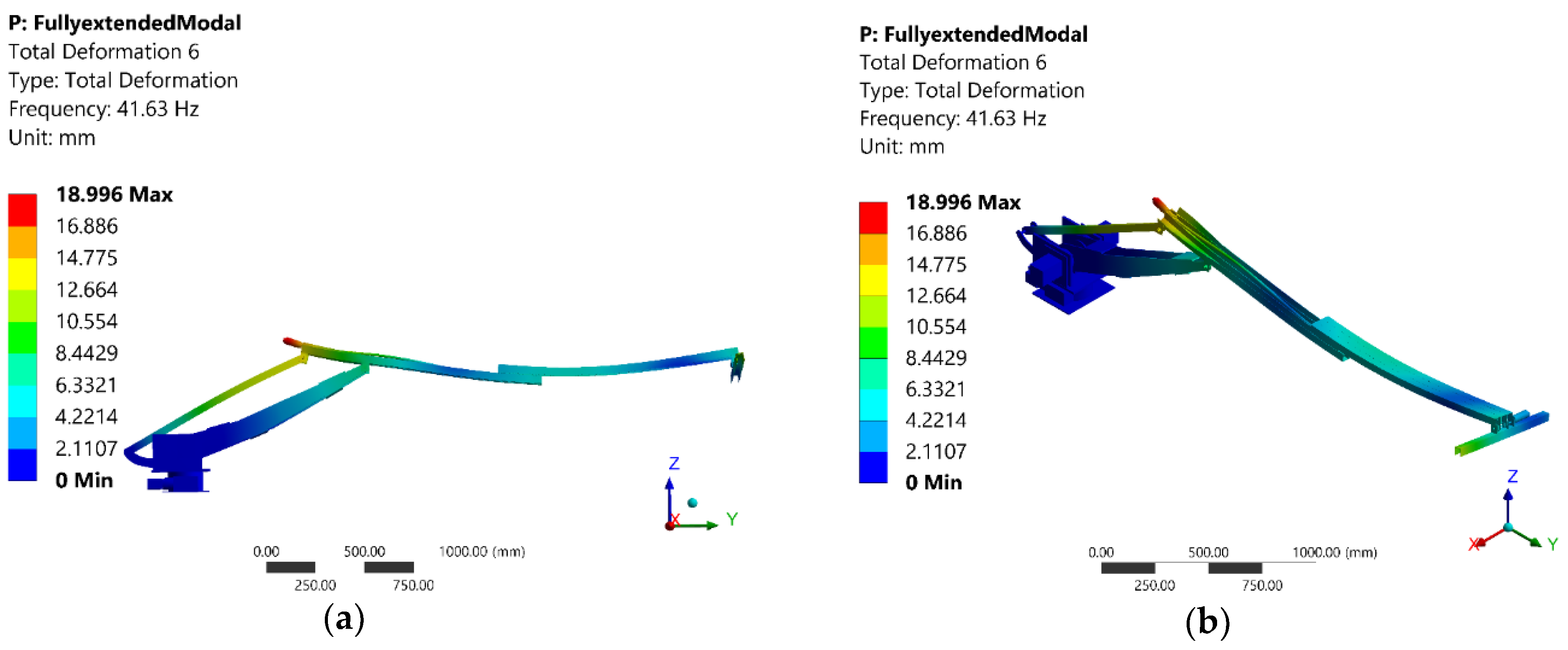
| 6. | 41.63 |
| Mode | Frequency [Hz] |
|---|---|
| 1. | 5.21 |
| 2. | 7.16 |
| 3. | 14.86 |
| 4. | 18.12 |
| 5. | 33.49 |
| 6. | 38.82 |
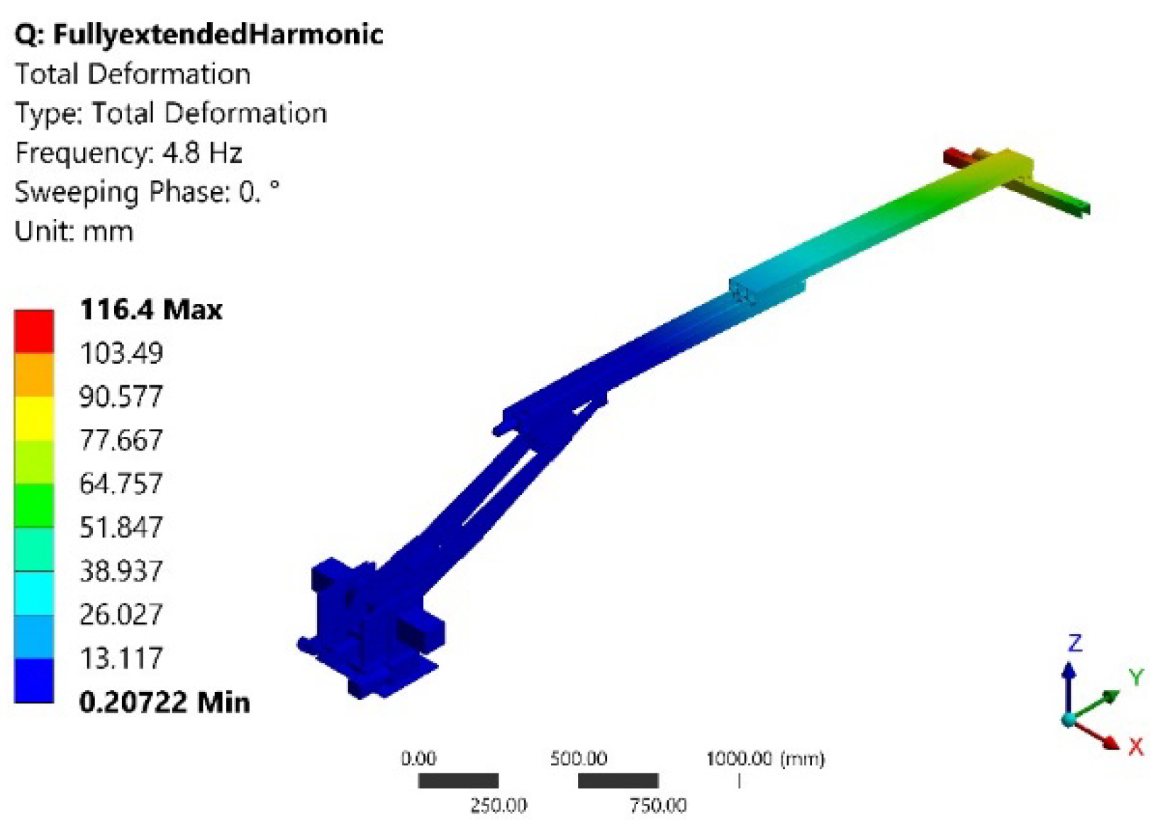
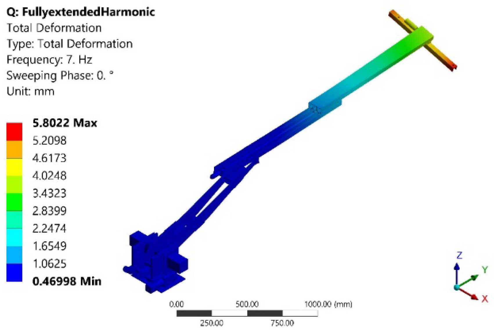
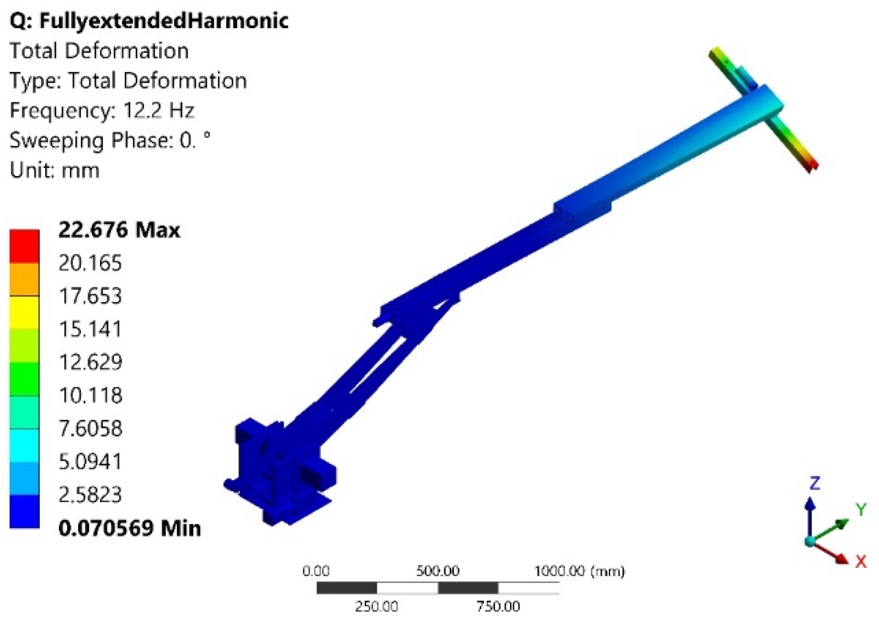
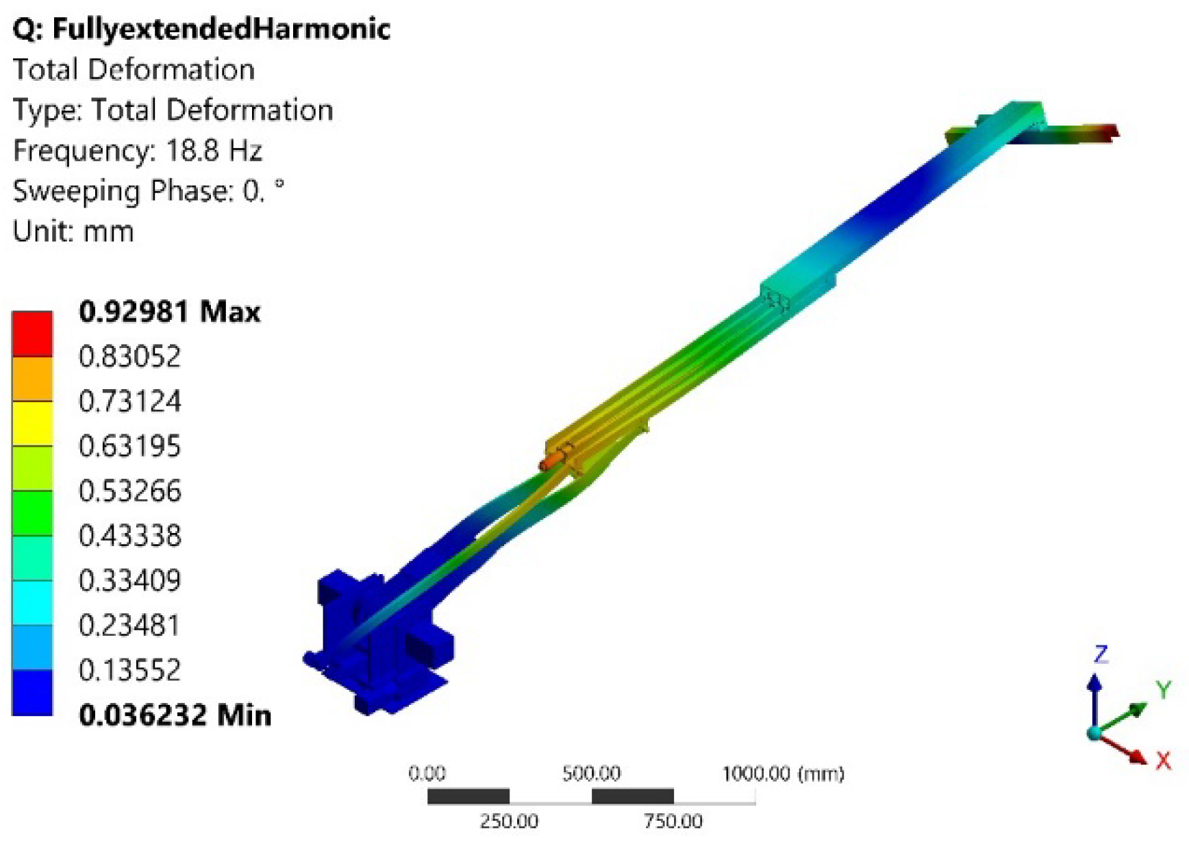
| Mode | Frequency [Hz] | Deformation Value (mm) | Deformation Location |
|---|---|---|---|
| 1 | 4.83 | 116.4 | End-effector |
| 2 | 7.10 | 5.802 | End-effector |
| 3 | 12.25 | 22.68 | End-effector |
| 4 | 18.84 | 0.929 | End-effector & Joint 4 |
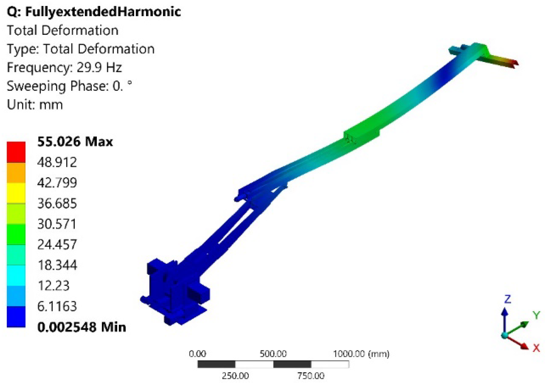
| 5 | 29.91 | 55.03 | End-effector |
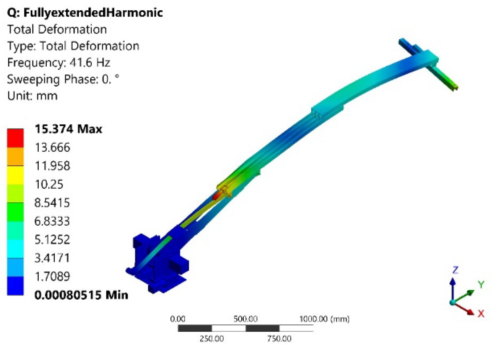
| 6 | 41.63 | 15.37 | Joint 4 |
| Mode | Experimental (Hz) | FEA (Hz) | Percentage Difference |
|---|---|---|---|
| 1’ | 3.1–3.56 | 3.2 | |
| 1 | 4.4 | 4.8 | |
| 2’ | 5–5.6 | 5.5 | |
| 2 | 6.4–7.2 | 7.1 | |
| 3 | 11.9–12.4 | 12.2 | |
| 4 | 18.6–21 | 18.8 | |
| 5 | 24–31.5 | 29.9 | |
| 6 | 38–43.2 | 41.6 |
Publisher’s Note: MDPI stays neutral with regard to jurisdictional claims in published maps and institutional affiliations. |
© 2022 by the authors. Licensee MDPI, Basel, Switzerland. This article is an open access article distributed under the terms and conditions of the Creative Commons Attribution (CC BY) license (https://creativecommons.org/licenses/by/4.0/).
Share and Cite
Badkoobehhezaveh, H.; Fotouhi, R.; Zhang, Q.; Bitner, D. Vibration Analysis of a 5-DOF Long-Reach Robotic Arm. Vibration 2022, 5, 585-602. https://doi.org/10.3390/vibration5030034
Badkoobehhezaveh H, Fotouhi R, Zhang Q, Bitner D. Vibration Analysis of a 5-DOF Long-Reach Robotic Arm. Vibration. 2022; 5(3):585-602. https://doi.org/10.3390/vibration5030034
Chicago/Turabian StyleBadkoobehhezaveh, Hedieh, Reza Fotouhi, Qianwei Zhang, and Douglas Bitner. 2022. "Vibration Analysis of a 5-DOF Long-Reach Robotic Arm" Vibration 5, no. 3: 585-602. https://doi.org/10.3390/vibration5030034