


On the Efficiency Enhancement of an Actively Tunable MEMS Energy Harvesting Device

Abstract
:1. Introduction
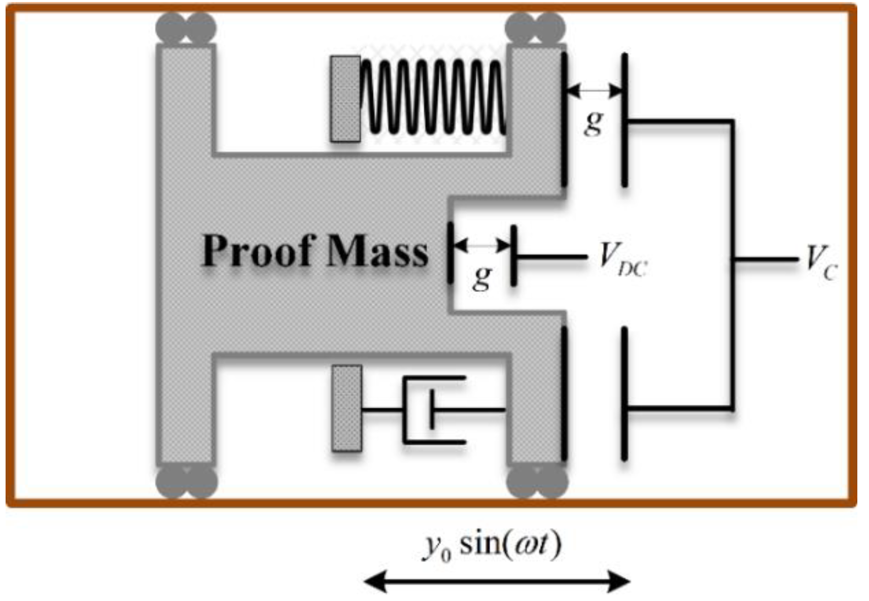
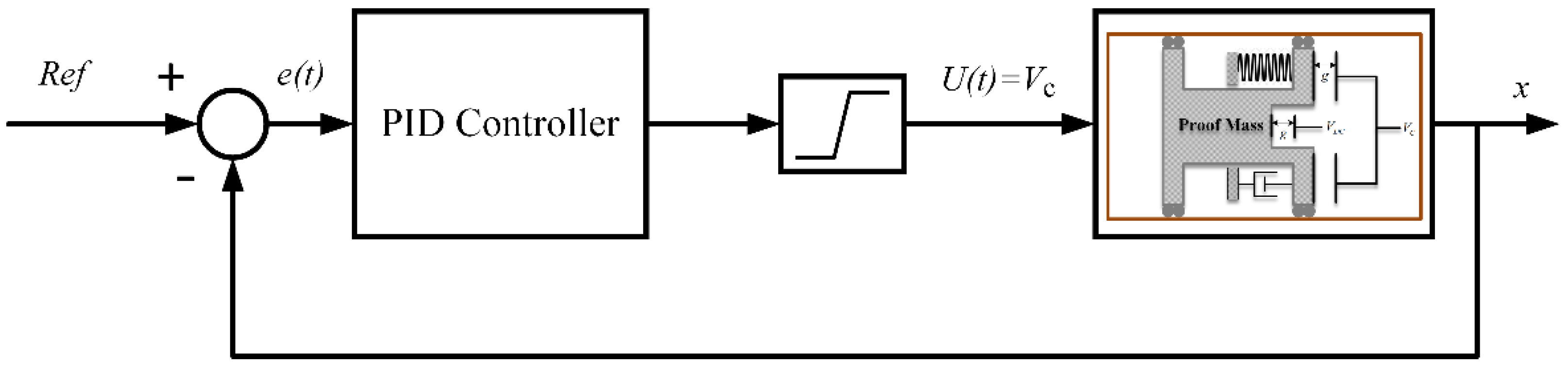
2. Modelling
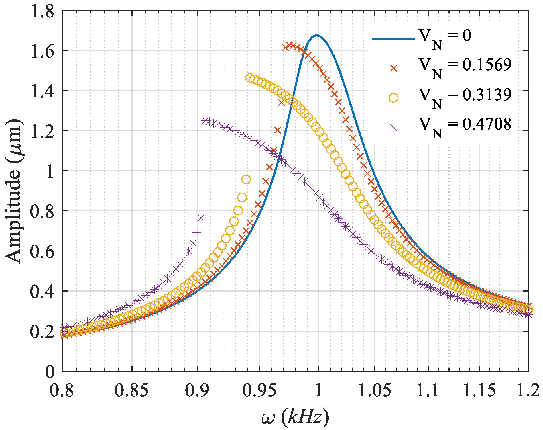
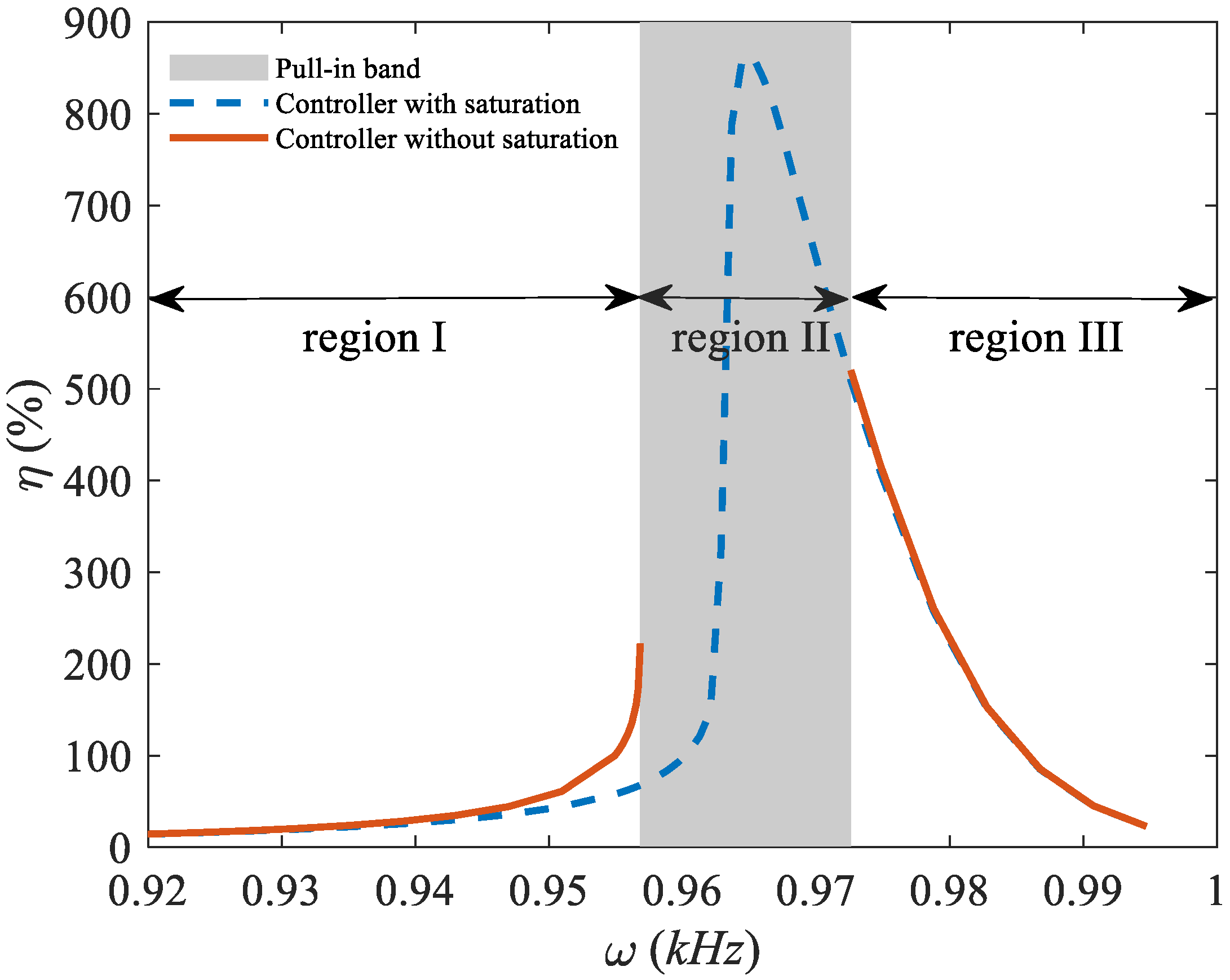
3. Results and Discussions
4. Conclusions
Author Contributions
Funding
Conflicts of Interest
References
- Azizi, S.; Madinei, H.; Taghipour, J.; Ouakad, H.M. Bifurcation analysis and nonlinear dynamics of a capacitive energy harvester in the vicinity of the primary and secondary resonances. Nonlinear Dyn. 2022, 108, 873–886. [Google Scholar] [CrossRef]
- Azizi, S.; Ghodsi, A.; Jafari, H.; Ghazavi, M.R. A conceptual study on the dynamics of a piezoelectric MEMS (Micro Electro Mechanical System) energy harvester. Energy 2016, 96, 495–506. [Google Scholar] [CrossRef]
- Jahanshahi, H.; Chen, D.; Chu, Y.-M.; Gómez-Aguilar, J.F.; Aly, A.A. Enhancement of the performance of nonlinear vibration energy harvesters by exploiting secondary resonances in multi-frequency excitations. Eur. Phys. J. Plus 2021, 136, 278. [Google Scholar] [CrossRef]
- Ali, F.; Raza, W.; Li, X.; Gul, H.; Kim, K.-H. Piezoelectric energy harvesters for biomedical applications. Nano Energy 2019, 57, 879–902. [Google Scholar] [CrossRef]
- Qi, L.; Pan, H.; Pan, Y.; Luo, D.; Yan, J.; Zhang, Z. A review of vibration energy harvesting in rail transportation field. iScience 2022, 25, 103849. [Google Scholar] [CrossRef]
- Cleante, V.G.; Brennan, M.J.; Gatti, G.; Thompson, D.J. Energy harvesting from the vibrations of a passing train: Effect of speed variability. J. Phys. Conf. Ser. 2016, 744, 012080. [Google Scholar] [CrossRef]
- Akbar, M.; Curiel-Sosa, J.L. Piezoelectric energy harvester composite under dynamic bending with implementation to aircraft wingbox structure. Compos. Struct. 2016, 153, 193–203. [Google Scholar] [CrossRef]
- Kammer, A.S.; Olgac, N. Delayed feedback control scheme for improved energy harvesting using piezoelectric networks. J. Intell. Mater. Syst. Struct. 2017, 29, 1546–1559. [Google Scholar] [CrossRef]
- Badel, A.; Guyomar, D.; Lefeuvre, E.; Richard, C. Efficiency Enhancement of a Piezoelectric Energy Harvesting Device in Pulsed Operation by Synchronous Charge Inversion. J. Intell. Mater. Syst. Struct. 2005, 16, 889–901. [Google Scholar] [CrossRef]
- Butram, V.; Naugarhiya, A. Performance Enhancement of Piezoelectric MEMS Energy Harvester Using Split Proof Mass for Powering Ultralow Power Wireless Sensor Nodes. Arab. J. Sci. Eng. 2022, 47, 2755–2762. [Google Scholar] [CrossRef]
- Zhou, K.; Dai, H.L.; Abdelkefi, A.; Ni, Q. Theoretical modeling and nonlinear analysis of piezoelectric energy harvesters with different stoppers. Int. J. Mech. Sci. 2020, 166, 105233. [Google Scholar] [CrossRef]
- Wu, H.; Tang, L.; Yang, Y.; Soh, C.K. Development of a broadband nonlinear two-degree-of-freedom piezoelectric energy harvester. J. Intell. Mater. Syst. Struct. 2014, 25, 1875–1889. [Google Scholar] [CrossRef]
- Ghavami, M.; Azizi, S.; Ghazavi, M.R. On the dynamics of a capacitive electret-based micro-cantilever for energy harvesting. Energy 2018, 153, 967–976. [Google Scholar] [CrossRef]
- Ghavami, M.; Azizi, S.; Ghazavi, M.R. Dynamics of a micro-cantilever for capacitive energy harvesting considering nonlinear inertia and curvature. J. Braz. Soc. Mech. Sci. Eng. 2022, 44, 124. [Google Scholar] [CrossRef]
- Lallart, M.; Wang, L.; Petit, L. Enhancement of electrostatic energy harvesting using self-similar capacitor patterns. J. Intell. Mater. Syst. Struct. 2016, 27, 2385–2394. [Google Scholar] [CrossRef]
- Takhedmit, H.; Saddi, Z.; Karami, A.; Basset, P.; Cirio, L. Electrostatic vibration energy harvester with 2.4-GHz Cockcroft–Walton rectenna start-up. Comptes Rendus Phys. 2017, 18, 98–106. [Google Scholar] [CrossRef]
- Jafari, H.; Ghodsi, A.; Azizi, S.; Ghazavi, M.R. Energy harvesting based on magnetostriction, for low frequency excitations. Energy 2017, 124, 1–8. [Google Scholar] [CrossRef]
- Giorgi, G.; Faedo, N. Performance enhancement of a vibration energy harvester via harmonic time-varying damping: A pseudospectral-based approach. Mech. Syst. Signal Process. 2022, 165, 108331. [Google Scholar] [CrossRef]
- Nie, X.; Tan, T.; Yan, Z.; Yan, Z.; Hajj, M.R. Broadband and high-efficient L-shaped piezoelectric energy harvester based on internal resonance. Int. J. Mech. Sci. 2019, 159, 287–305. [Google Scholar] [CrossRef]
- Liu, H.; Gao, X. Vibration energy harvesting under concurrent base and flow excitations with internal resonance. Nonlinear Dyn. 2019, 96, 1067–1081. [Google Scholar] [CrossRef]
- Challa, V.R.; Prasad, M.G.; Shi, Y.; Fisher, F.T. A vibration energy harvesting device with bidirectional resonance frequency tunability. Smart Mater. Struct. 2008, 17, 015035. [Google Scholar] [CrossRef]
- Shi, G.; Yang, Y.; Chen, J.; Peng, Y.; Xia, H.; Xia, Y. A broadband piezoelectric energy harvester with movable mass for frequency active self-tuning. Smart Mater. Struct. 2020, 29, 055023. [Google Scholar] [CrossRef]
- Lihua, C.; Jiangtao, X.; Shiqing, P.; Liqi, C. Study on cantilever piezoelectric energy harvester with tunable function. Smart Mater. Struct. 2020, 29, 075001. [Google Scholar] [CrossRef]
- Li, M.; Jing, X. Novel tunable broadband piezoelectric harvesters for ultralow-frequency bridge vibration energy harvesting. Appl. Energy 2019, 255, 113829. [Google Scholar] [CrossRef]
- Kamali, S.H.; Moallem, M.; Arzanpour, S. A self-tuning vibration energy harvester with variable loads and maximum allowable displacement. Smart Mater. Struct. 2018, 27, 105015. [Google Scholar] [CrossRef]
- Staaf, L.G.H.; Smith, A.D.; Lundgren, P.; Folkow, P.D.; Enoksson, P. Effective piezoelectric energy harvesting with bandwidth enhancement by assymetry augmented self-tuning of conjoined cantilevers. Int. J. Mech. Sci. 2019, 150, 1–11. [Google Scholar] [CrossRef]


| M | 1 μg |
|---|---|
| k | 40 N/m |
| b | 0 |
| A | 104 μm2 |
| g | 2 μm |
| R | 1GΩ |
| VDC | 5 kv (CYPTOS as the electret layer) |
Publisher’s Note: MDPI stays neutral with regard to jurisdictional claims in published maps and institutional affiliations. |
© 2022 by the authors. Licensee MDPI, Basel, Switzerland. This article is an open access article distributed under the terms and conditions of the Creative Commons Attribution (CC BY) license (https://creativecommons.org/licenses/by/4.0/).
Share and Cite
Aliasghary, M.; Azizi, S.; Madinei, H.; Haddad Khodaparast, H. On the Efficiency Enhancement of an Actively Tunable MEMS Energy Harvesting Device. Vibration 2022, 5, 603-612. https://doi.org/10.3390/vibration5030035
Aliasghary M, Azizi S, Madinei H, Haddad Khodaparast H. On the Efficiency Enhancement of an Actively Tunable MEMS Energy Harvesting Device. Vibration. 2022; 5(3):603-612. https://doi.org/10.3390/vibration5030035
Chicago/Turabian StyleAliasghary, Mortaza, Saber Azizi, Hadi Madinei, and Hamed Haddad Khodaparast. 2022. "On the Efficiency Enhancement of an Actively Tunable MEMS Energy Harvesting Device" Vibration 5, no. 3: 603-612. https://doi.org/10.3390/vibration5030035