Article

Parametric Instability of Functionally Graded Porous Cylindrical Panels under the Effect of Static and Time-Dependent Axial Loads

Department of Mechanical Engineering, College of Engineering, University of Anbar, Ramadi 31001, Iraq
*
Author to whom correspondence should be addressed.
Vibration 2022, 5(3), 570-584; https://doi.org/10.3390/vibration5030033
Submission received: 27 July 2022 / Revised: 20 August 2022 / Accepted: 29 August 2022 / Published: 2 September 2022
(This article belongs to the Topic Dynamical Systems: Theory and Applications)

Abstract

:
This work presents an analytical study of the parametric instability of cylindrical panels containing functionally graded porous exposed to static and dynamic periodic axial loads under simply supported boundary conditions. Based on Hamilton’s principle, the governing equation of motion by using first-order shear deformation theory (FSDT) has been obtained. By applying the Galerkin technique, an excitation frequency expression is derived, which helps identify areas of instability of functionally graded porous cylindrical panels. Numerical simulations are used to validate the analytical results. Eventually, the impacts of the porosity coefficient, porosity distribution method, static and dynamic periodic axial loads, panel angle, circumferential wave number, and cylindrical panel characteristics on the region of instability are displayed in the section of results and discussions. The findings show that when the porosity is further from the surface, the more stable the structure is. Furthermore, a small angle of the cylindrical panels gives a better dynamic response than a large angle. In addition, increased static and dynamic loads lead to an expansion of areas of instability.

1. Introduction

The presence of porosity in a structure makes its strength-to-weight ratio very good as compared to the strength of homogeneous isotropic materials at the same weight, as well as being permeable and a thermal insulator [1]. Consequently, cylindrical panels are key structural elements present in a wide range of engineering fields, including aircraft, petrochemicals, nuclear reactors, the maritime industry, and mechanical engineering [2]. The stable performance of functionally graded porous (FGP) cylindrical panels is affected by a variety of mechanical loads (i.e., static axial load and time-dependent load). Many studies were performed on the free vibration of cylindrical shells made of homogeneous isotropic and functionally graded porous by existing authors [3,4,5,6,7], and for rotating cylindrical shells made of homogeneous isotropic, multilayered, functionally graded materials and CNT-reinforced functionally graded materials, graded graphene, functionally graded porous materials, and stiffened functionally graded porous [8,9,10,11,12,13,14,15]. Authors have investigated linear and nonlinear free vibration of cylindrical panels made of homogeneous isotropic and functional graded porous materials, and analyses based on different shear deformation theories were performed in [16,17]. The effect of rotating on the cylindrical panel behavior made of an isotropic martial was examined in [18]. The study of a free vibration composite panel reinforced by CNT functionally graded panels based on the element-free KP–Ritz method under different boundary conditions was investigated in [19]. Hong et al. [20] examined the natural frequency of functionally graded cylindrical and parabolic panels based on the Fourier–Ritz approach under various boundary conditions. Dong et al. [21] studied the dynamic responses of the forward and backward traveling waves of functionally graded graphene-reinforced cylindrical shells under the effects of angular velocity and axial static load. Li et al. [22] investigated the combined impacts of subsonic airflow and hygrothermal on the natural frequencies and critical rotating velocity of a composite laminated cylindrical shell; this study’s findings were based on Love’s nonlinear shell theory. Liew et al. [23] investigated the vibration of a three-layer coating–FGM–substrate cylindrical panel with an effect of increased temperature gradient due to being exposed to stable heat conduction through thickness under different boundary conditions, and this study has been performed based on first-order shear deformation theory (FSDT). SafarPour et al. [24] used the first-order shear deformation theory to study the effects of high spinning motion and critical voltage on the buckling and free vibration of piezoelectric cylindrical materials reinforced by CNT with different boundary conditions. Chen et al. [25] studied three solutions to the vibration behavior of pre-twisted isotropic and FGM cylindrical shell panels under the impact of angular velocity. The results of this study were obtained by taking into account the effect of centrifugal stress. Quang Chan et al. [26] investigated the effect of compressive load on the nonlinear buckling and post-buckling of sandwich cylindrical panels containing a porous core and two surfaces functionally graded with two boundary conditions: one is four edges simply supported (SSSS) and the other condition is two edges simply supported and two edges clamped (SSCC). The authors of [27,28,29,30] studied the effects of static and dynamic axial forces and angular velocity on the instability behavior of isotropic and CNTRC cylindrical shells. Han and Chu [31] investigated the region of instability of truncated conical shells for different boundary conditions under impact periodic rotation; Love’s thin shell theory and the generalized differential quadrature (GDQ) method were used in the approach. Li et al. [32] investigated the instability of FG cylindrical shells subjected to rotation and thermal effects, taking into consideration that the properties of shells were dependent on the temperature. Li et al. [33] studied the unstable behavior of rotating truncated conical shells reinforced by functionally graded graphene under the impacts of time-dependent loads and thermal expansion deformation, Love’s thin shell theory and the Galerkin method served as the foundation for the methodology. Phu [34] used the geometrical characteristics of nonlinearity in the von Karman–Donnell hypothesis and classical shear theory to study instability behavior for varying thicknesses of functionally graded cylindrical shells. Zhao et al. [35] studied the instability behavior of FG porous arches reinforced by graphene platelets under the effects of static and dynamic forces. The study was performed based on the classical Euler–Bernoulli theory. Han et al. [36] studied the dynamic stability of simply supported thin circular cylindrical shells under the effects of constant and harmonic rotating speeds based upon Love’s thin shell theory. Pellicano and Amabili [37] studied the stability and post-critical dynamics of a simply supported cylindrical shell filled with fluid under the effect of dynamic and static axial loads based on Donnell’s nonlinear shallow-shell theory. The authors of [38,39,40] studied the influence of periodic axial loads on the parametric instability of simply supported cylindrical shells, made of functionally graded materials, a sandwich containing FG core, and exponentially graded sandwich materials, respectively.
To the best of the authors’ knowledge, there is no research done on the linear dynamic stability of functionally graded porous (FGP) cylindrical panels under the impacts of static and dynamic forces. Hence, the present study is focused on the instability analysis of cylindrical panels, the governing equations of motion were derived based on first-order shear deformation theory (FSDT) by using Hamilton’s principle, and then applying the Galerkin method to obtain the excitation frequencies; this is a straightforward method for analyzing the linear parametric instability of simply supported FGP panels subjected to the combined effects of static and dynamic axial loads. In the section on numerical results, the influences of the porosity distribution, coefficient of porosity, circumferential wave number, geometric parameters, static load factor, and dynamic load factor on the dynamic stability of the FGP cylindrical panels are presented and discussed.

2. Theoretical Approach

The parameters of functional graded porous cylindrical panels under study are symbolized as thickness: h; length: L; angle: θo; mean radius: R; square plan form: b; circumferential length: S, as shown in Figure 1. An orthogonal coordinate (X, θ, Z) is used to identify the structure’s axes. The X and θ axes are the longitudinal and circumferential directions of the panels, respectively, and Z is the radial direction of the panels along the thickness.

2.1. The Governing Equations of the Distribution of Porosity

In this work, three types of porosity distributions were investigated, as shown in Figure 2 [17]. Type 1 is the uniform spread of porosity along the thickness direction and the properties of materials are constant (denoted by Type 1). The second type is a nonuniform symmetric distribution about the center. In this type, the midplane of the panel has the maximum porosity and the maximum stiffness is on the surfaces of panels (denoted by Type 2). The third type is a symmetric porosity about surfaces. This type has the maximum porosity on the top and bottom surfaces of the panel and the midplane of the panel has the maximum stiffness (denoted by Type 3).
The governing equations of the three types of distribution can be defined as [15]:
Type 1:
[ E ( z ) , ρ ( z ) ] = ( E 0 , ρ 0 ) ( 1 ( e 0 , e m * ) λ )
Type 2:
[ E ( z ) , ρ ( z ) ] = ( E 0 , ρ 0 ) ( 1 ( e 0 , e m ) c o s ( π z h ) )
Type 3:
[ E ( z ) , ρ ( z ) ] = ( E 0 , ρ 0 ) ( 1 ( e 0 , e m ) s i n ( | π z h | ) )
where e 0 is the porosity coefficient, its value (0 < e 0 < 1), which can be calculated as [17] e 0 = 1 E min / E 0   e m * is the porosity coefficient of the mass density of Type 1 distributions, which can be calculated as [17] e m * = ( ( 1 1 e 0 λ ) / λ ) , E 0 , ρ 0 , E min , ρ min . λ in Equation (1) for Type 1 distributions can be calculated as λ = 1 e 0 ( 1 ( 1 2 e m π ) 2 ) . e m is the porosity coefficient of mass density for Type 2 and Type 3 distributions, which can be calculated as e m = 1 1 e 0 or e m = 1 ρ min / ρ 0 .
E 0 , E min , ρ 0 , ρ min are the maximum and minimum values of elastic moduli and density, respectively.

2.2. Formulation of Dynamic Stability

The displacement field equation can be defined based on Donell’s shell theory using first-order shear deformation theory (FSDT) [41]:
U ( x , θ , z , t ) = u ( x , θ , t ) + z φ x ( x , θ , t ) V ( x , θ , z , t ) = v ( x , θ , t ) + z φ θ ( x , θ , t ) W ( x , θ , z , t ) = w ( x , θ , t )
where ( u , v , w ) symbolize the displacement of a point in x , θ , z directions, respectively, at z = 0 . φ x symbolizes the rotation of the normal about the θ axis, φ θ denotes the rotation of the normal about the x axis. The strain–displacement relation can be calculated as:
ε x =   u   x + z   φ x   x , ε θ =   v R   θ + w R + z   φ θ R   θ , γ x z = φ x +   w   x γ x θ =   u R   θ +   v   x + z (   φ x R   θ +   φ θ   x ) , γ θ z = φ θ +   w R   θ v R
To derive the governing partial differential equations of motion, Hamilton’s principle is used in the following form:
δ t 1 t 2 ( U T V ) d t = 0
where δ is the variation operator, t 1 , t 2 are two arbitrary times. U denotes potential energy. T denotes kinetic energy, V denotes work done generated from static and dynamic axial forces.
U = 1 2 0 L 0 θ 0 h 2 h 2 ( σ x x ε x x + σ θ θ ε θ θ + σ x θ γ x θ + σ x z γ x z + σ θ z γ θ z ) R d z d θ d x
The stresses in Equation (7) are given based on Hook’s law, as follows:
( σ x σ θ ) = E ( z ) 1 μ 2 ( ε x + μ ε θ ε θ + μ ε x ) , σ x θ = E ( z ) 2 ( 1 + μ ) γ x θ , ( σ x z σ θ z ) = k E ( z ) 2 ( 1 + μ ) ( γ x z γ θ z )
μ denotes Poisson’s ratio and is assumed a constant value compared with other mechanical characteristics of the FGP cylindrical panel [17]. k denotes the shear correction factor ( k = 5/6) [30].
T = 1 2 0 L 0 θ 0 h 2 h 2 ρ ( z ) ( (   U   t ) 2 + (   V   t ) 2 + (   W   t ) 2 ) R d z d θ d x
V = 1 2 0 L 0 θ 0 N x ( t ) (   w   x ) 2 R d θ d x
N x ( t ) is the uniformly distributed axial periodic load per unit length,
N x ( t ) = N 0 + N t cos ( Ω t )
N 0 is the static axial load, N t is the time-dependent axial load, Ω refers to the excitation frequency in radian per unit time, and t denotes the time variable. Substituting Equations (7)–(10) into Equation (6), we obtain the governing partial differential equations of motion:
δ u :   N x x   x +   N x θ R   θ = I 0 2 u   t 2 + I 1 2 φ x   t 2 δ v :   N θ θ R   θ +   N x θ   x + Q θ R = I 0 2 v   t 2 + I 1 2 φ θ   t 2 δ w : N x x 2 w   x 2 + N θ θ R + N θ θ 2 w R 2   θ 2 + N x θ 2 w R   θ   x +   Q x   x +   Q θ R   θ N x ( t ) 2 w   x 2 = I 0 2 w   t 2 δ φ x :   M x x   x +     M x θ R   θ Q x = I 1 2 u t 2 + I 2 2 φ x   t 2 δ φ θ :   M θ θ R   θ +   M x θ   x Q θ = I 1 2 v t 2 + I 2 2 φ θ   t 2
where ( N x , N θ , N x θ , Q x , Q θ ) are the force resultants and ( M x , M θ , M x θ ) are the moment resultants, which are expressed as follows [40].
[ N x x N θ θ N x θ ] = h 2 h 2 [ σ x x σ θ θ σ x θ ] d z ,     [ M x x M θ θ M x θ ] = h 2 h 2 [ σ x x σ θ θ σ x θ ] z d z ,     [ Q x Q θ ] = h 2 h 2 [ σ x z σ θ z ] d z
I 1 i = E i 1 μ 2 ,     I 2 i = μ I 1 i ,     I 3 i = E i 2 ( 1 + μ )   ( i = 0 , 1 , 2 ) ( E 0 , E 1 , E 2 ) = h 2 h 2 E ( z ) ( 1 , z , z 2 ) d z , ( I 0 , I 1 , I 2 ) = h 2 h 2 ρ ( z ) ( 1 , z , z 2 ) d z
Now, we substitute Equation (5) into Equation (8), and then into Equation (13), and rewrite the equations of motion in the following form:
[ L 11     L 12     L 13     L 14     L 15 L 21     L 22     L 23     L 24     L 25 L 31     L 32     L 33     L 34     L 35 L 41     L 42     L 43     L 44     L 45 L 51     L 52     L 53     L 54     L 55 ] [ u v w φ x φ θ ] = 0
The effects of the inertia forces of rotation and midplane displacement have been neglected because they are smaller than the inertia force from transverse displacement (w) [40], where L ij ( i , j = 1 , 2 , 3 , 4 , 5 ) is the operator of the partial differential equation. The cylindrical panels are assumed to be simply supported at both ends at x = 0, L and corresponding to the boundary condition as ( v = w = φ θ = N x x = M x x = 0   at   x = 0 , L ) .
The approximate solution that satisfies boundary conditions can be assumed to solve Equation (14) of the functionally graded porous cylindrical panel is as follows [21]:
u ( x , θ , t ) = ( u 1 c o s β θ u 2 s i n β θ ) c o s α x v ( x , θ , t ) = ( v 1 s i n β θ v 2 c o s β θ ) s i n α x w ( x , θ , t ) = ( w 1 c o s β θ w 2 s i n β θ ) s i n α x φ x ( x , θ , t ) = ( φ x 1 c o s β θ φ x 2 s i n β θ ) c o s α x φ θ ( x , θ , t ) = ( φ θ 1 s i n β θ φ θ 2 c o s β θ ) s i n α x
where (n, m) are the half-circumferential and axial wave numbers, respectively, β = n π / θ 0 ,   α = m π / L . After substituting Equation (15) into Equation (14) and converting the partial differential equation to an ordinary differential equation by using superposition theory, the ordinary differential equations of cylindrical panels are obtained as:
[ Γ 11     Γ 12     Γ 14     Γ 15 Γ 21     Γ 22     Γ 24     Γ 25 Γ 41     Γ 42     Γ 44     Γ 45 Γ 51     Γ 52     Γ 54     Γ 55 ] [ u 1 v 1 φ x 1 φ θ 1 ] = [ Γ 13 Γ 23 Γ 43 Γ 53 ] w 1
[ Γ 11     Γ 12     Γ 14     Γ 15 Γ 21     Γ 22     Γ 24     Γ 25 Γ 41     Γ 42     Γ 44     Γ 45 Γ 51     Γ 52     Γ 54     Γ 55 ] [ u 2 v 2 φ x 2 φ θ 2 ] = [ Γ 13 Γ 23 Γ 43 Γ 53 ] w 2
Γ 31 u 1 + Γ 32 v 1 + ( Γ 33 + N x ( t ) α 2 ) w 1 + Γ 54 φ x 1 + Γ 55 φ θ 1 = I 0 d 2 w 1 d t 2 Γ 31 u 2 Γ 32 v 2 + ( Γ 33 + N x ( t ) α 2 ) w 2 + Γ 54 φ x 2 Γ 55 φ θ 2 = I 0 d 2 w 2 d t 2
where Γ i j   ( i , j = 1 , 2 , 3 , 4 , 5 ) are defined in Appendix A. So, from Equations (16) and (17) we can derive the relation between ( u i , v i , φ xi , φ θ i ) and ( w i ) ,   ( i = 1 , 2 ) , defined as:
u 1 = D w 1 v 1 = K w 1 φ x 1 = t w 1 φ θ 1 = H w 1
u 2 = D w 2 v 2 = K w 2 φ x 2 = t w 2 φ θ 2 = H w 2
The constants D , K , t , H are shown in Appendix B, and then, substituting Equations (19) and (20) into Equation (18), after some mathematical manipulation, we obtain the following relationship:
I 0 d 2 w d t 2 + ( F N x ( t ) α 2 ) w = 0
d w d t = [ d w 1 d t d w 2 d t ] , w = [ w 1 w 2 ] , F = ( Γ 31 D + Γ 32 K + Γ 33 + Γ 34 t + Γ 35 H )
The critical buckling periodic loads are obtained from Equation (21) by neglecting the mass term [30], so ( N c r = F / α 2 ) .
If we need natural frequency without periodic axial loads obtained from Equation (21),
ω = F / I 0
In the present study, the parametric instability is bounded by two periods, T and 2T, with T = 2 π [39]. The solution to Equation (21) corresponds to 2T because the width of instability at period 2T is usually larger than T, and is assumed as [38]:
w = a   c o s Ω 2 t + b   s i n Ω 2 t
where ( a , b ) are constants and p is the excitation frequency. Substituting Equation (23) into Equation (21) and applying Galerkin’s method with periodic 2T to obtain an expression of the excitation frequency of (FGP) a cylindrical panel with the effect of the periodic load, we can define the expression as an eigenvalue problem:
I 0 4 Ω 2 + F ( 1 N 01 0.5 N t 1 ) = 0 I 0 4 Ω 2 + F ( 1 N 01 + 0.5 N t 1 ) = 0
Now, we rewrite Equation (24) in a new form after mathematical manipulation, as follows:
Ω 1 , 2 = 4 ω 1 N 01 0.5 N t 1
N 01 is static load factor = N 0 / N c r , N t 1 is dynamic load factor = N t / N c r , the negative signal gives Ω 1 , and the positive signal gives Ω 2 . The dimensionless excitation frequency is defined as follows:
P i , j = Ω i , j R ρ ( 1 μ 2 ) E ( i , j = 1 , 2 )

3. Numerical Results and Discussions

3.1. Validation

The instability analysis has been validated, so three numerical examples are examined for a cylindrical panel, a cylindrical shell made of homogeneous isotropic material, an FG porous material, and sandwich shells containing an FG core material, respectively.
Example 1.
The validation of the natural frequency of the isotropic cylindrical panel is shown in Table 1 and against results taken from Soldatos and Hadjigeorgiou [16]. In this example, there are three different values of the parameter h/b (0.1, 0.2, and 0.3) and different panel angles ( θ 0 = 30 , 60 , 90 ). L = b ,   S = ( b θ 0 / 2 sin ( θ 0 / 2 ) ) , where b is the square plan form, and the panel characteristic R = 1 m and mechanical properties are E = 200 Gpa, ρ = 7850 kg/ m 3 μ = 0.3. Equation (22) is used to compare with Soldatos and Hadjigeorgiou’s smallest first four frequency parameters [16]. The reliability of the results is good between the present result and the result of [16], as shown in Table 1.
Example 2.
The comparison of instability under effect periodic loads has been compared with SofIiyev and Kuruoglu [39] for sandwich cylindrical shells containing an FG core. The top layer is made of a metal-rich material, i.e., nickel (Ni), the bottom layer is made of a ceramic-rich material, i.e., silicon nitride (Si3N4), and the core of the shell is functionally graded through thickness from Si3N4 to Ni and the equations of elastic modulus and density are:
( E , ρ ) = E m , ρ m ( h 2 z a ) + E ( z ) , ρ ( z ) + E c , ρ c ( a z h 2 ) ( E ( z ) , ρ ( z ) ) = a a [ ( ( E m , ρ m ) ( E c , ρ c ) ) V c + ( ( E c , ρ c ) ) ] d z , V c = ( z + a 2 a ) d
where (d) denotes the volume friction index, (a) refers to the half thickness of core, and the geometrical dimensions and mechanical properties are θ 0 = 2 π , L/R = 0.1, R/h = 25, h/a = 4, E m = 205.09 Gpa, ρ m = 8900 kg/ m 3 , μ m = 0.31, E c = 322.271 Gpa, ρ c = 2370 kg/ m 3 , μ c = 0.24, and N t 1 = 0, 0.1, 0.3, 0.5, and N 01 = 0.2; see Table 2 for different wave numbers (m,n) = (1,1) and (1,3), and for a different volume friction index, d = 0.5, 2. The results have been obtained based on the first-order shear deformation theory. The results show good agreement between the present study and the results of SofIiyev and Kuruoglu [39].
Example 3.
We compare the results of Yuewu and Dafang [7] for functional graded porous materials for the cylindrical shells with different values of the porosity coefficient and circumferential wave number based on Type 2 distributions, as shown in Table 3. The numerical results were performed based on Equation (22), the dimension of the cylindrical shell and material properties are h/R = 0.01, L/R = 0.2, E = 200 Gpa, ρ = 7850   kg / m 3 , μ = 0.3 , and the dimensionless natural frequency ϖ = ω R ρ / E . The results of the present study agree with the results of Yuewu and Dafang [7].

3.2. Results of the Present Study

In the present study, the dynamic stability of FG porous cylindrical panels is investigated under the impact of the porosity coefficient, porosity distribution, wave numbers, geometrical dimensions, static load factor, and dynamic load factor. The dimensionless excitation frequencies are obtained by applying Equation (26). The mechanical properties are [17] E 0 = 200 Gpa, ρ 0 = 7850 kg/ m 3 , μ = 0.3, and the mean radius of the cylindrical panel is constant, i.e., R = 1 m. h/R = 0.05, L/S = 2, θ 0 = 100 ° are assumed to be constant values unless otherwise specified.

3.2.1. The Effect of Porosity Distribution

Figure 3 shows the effect of porosity distribution versus dynamic load on the instability of the FGP cylindrical panel, e 0 = 0.4, static load factor 0.5, and wave number (m,n) is (1,2). The results show that Type 2 distributions give the largest values of dimensionless excitation frequencies compared to other types. The results appear to show that Type 2 distributions provide the highest values of dimensionless excitation frequencies compared to other types, which is due to the surfaces’ resistance to loads and deformation due to the lack of porosity at the surfaces, resulting in higher density and stiffness at the surface panel than other types. On the other hand, to enhance the stability of the structure, the porosity of the surface must be prevented. The closer the porosity is to the center, the stronger the structure will be than if the porosity was closer to the surface.

3.2.2. The Effect of the Panel’s Angle

The effect of the angle of the panels on the instability of the structure is shown in Figure 4, with the values of N 01 = 0.2, e 0 = 0.4, and m = n = 1. The results reveal that the width of the instability region of the small angle, such as θ 0 = 30 ° , increases greater than the large angle of the panel, and the origin point of instability is greater than the large angle. The reason is that when the angle increases, the flexural rigidity of the panel drops, and the decreasing amplitude of the natural frequency becomes larger with the rise of the panel angle.

3.2.3. The Effect of the Porosity Coefficient

The examined coefficient of porosity for Type 2 distributions against the dynamic load factor on the dimensionless excitation frequencies is presented in Figure 5. The values of the static load and wave number are N 01 = 0.2, m = n = 1, respectively. The results show the instability of the structure decreases and is wider as the porosity coefficient increases. The reason for that is the decrease in both the stiffness and mass density of the panel. The increase in the porosity coefficient of the cylindrical panel results in extra foam in the structure, resulting in more weakness in the bending stiffness.

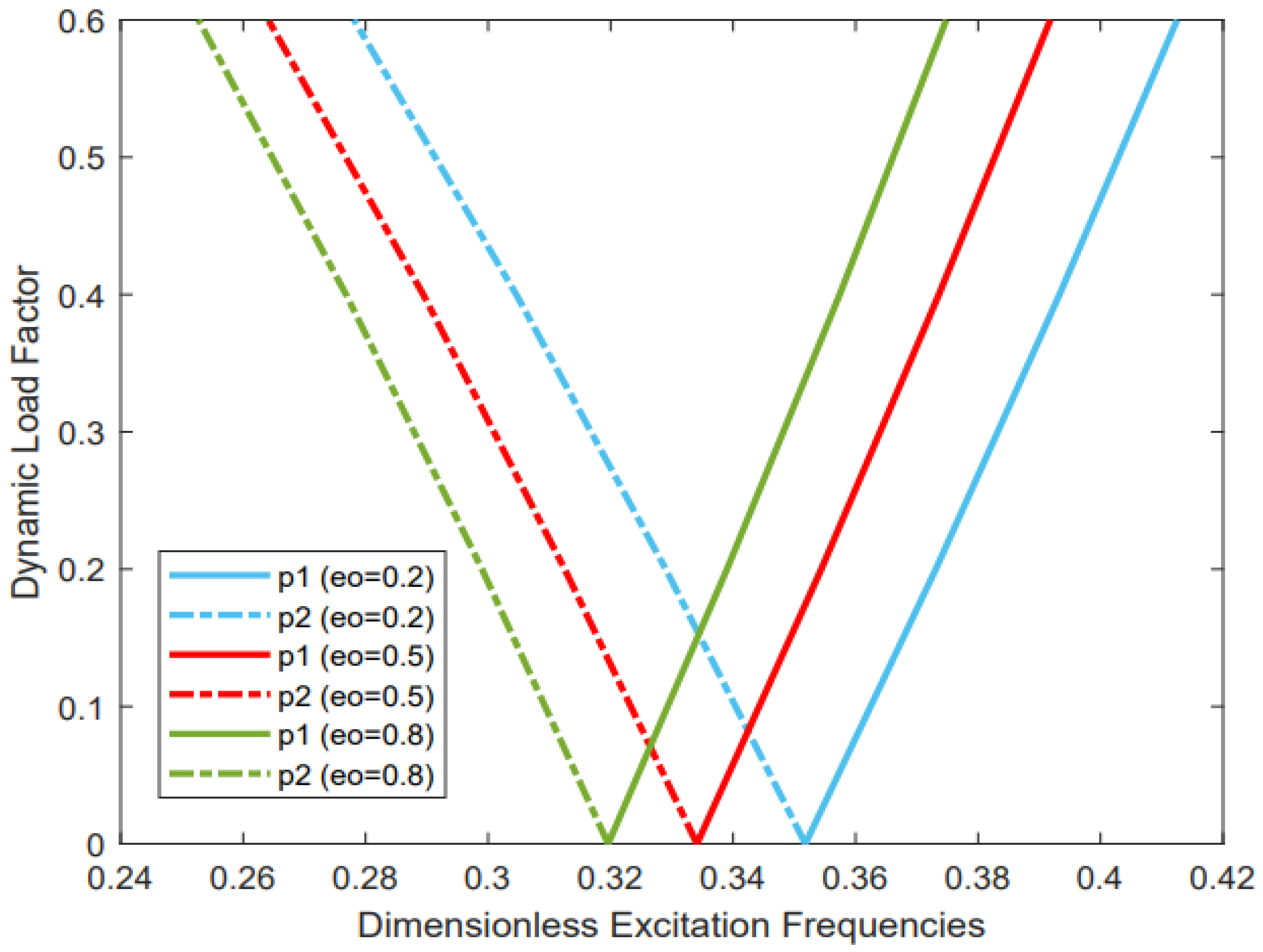
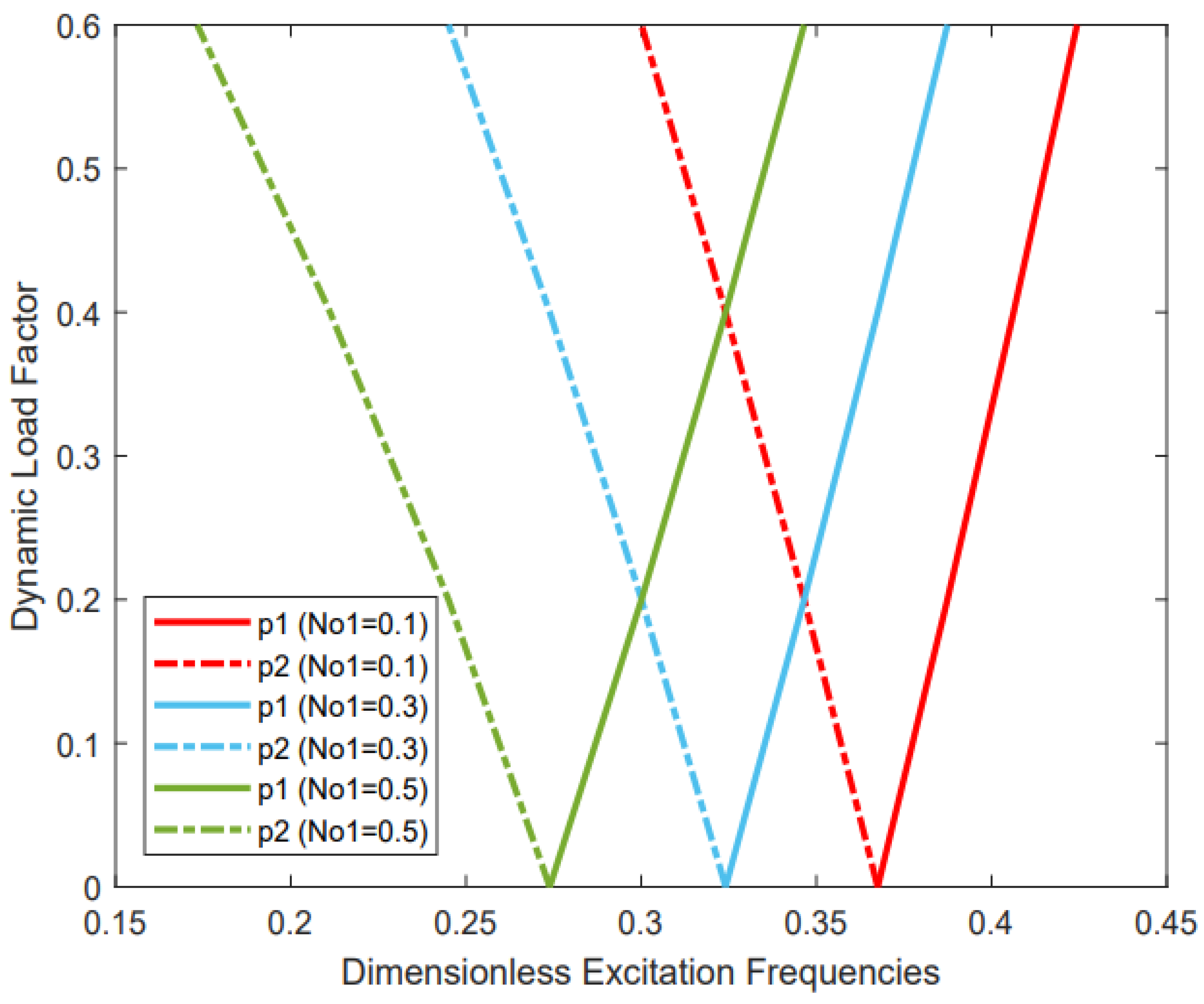
3.2.4. The Effect of Static and Dynamic Load Factors

Figure 6 examines the effects of static and dynamic load on the linear parametric instability of the cylindrical panel with a different dynamic load factor. The geometric properties of the panel are coefficients of porosity, i.e., e 0 = 0.4 and (m,n) = (1,2). It is detected that the value of the origin point of the boundary instability region shifts forward to a high value when the static load factor decreases, and the width of the instability region is wider when the static load factor and dynamic load factor increase. The existence of dynamic load leads to the instability region appearing and the boundary of instability beginning to shift to the left. That means the structure’s resistance and response dynamics decrease when the static load increases. The structure approaches failure whenever the static and dynamic load factors equal the critical value, and this means that the structure does not weaken only when the porosity increases but also weakens when the static load factor increases.

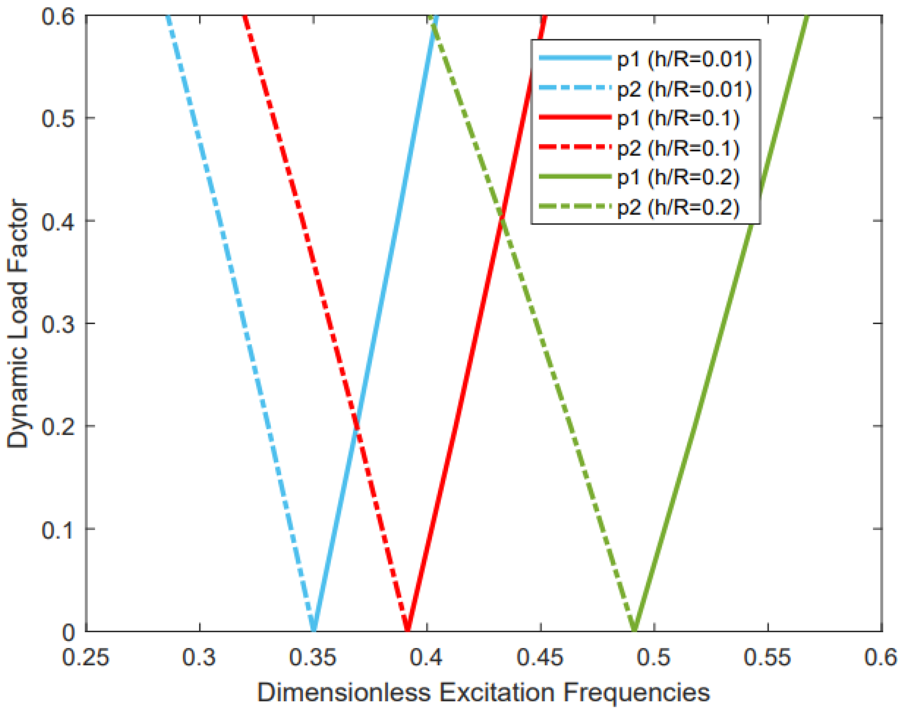
3.2.5. The Effect of the h/R Ratio

In Figure 7, the influence of the thickness-to-radius ratio on the behavior of the instability of a structure has been presented. The cylindrical panel parameters are N 01 = 0.1, and the various values of the radius-to-thickness ratio are 0.01, 0.1, and 0.2. Figure 7 shows that the dimensionless excitation frequencies increase by about 28.2% when the thickness increases from 0.01 to 0.2, and the instability regions are significantly wider when the thickness-to-radius ratio increases. To explain this behavior, we can say that the stiffness of the structure increases with the increase of the thickness.

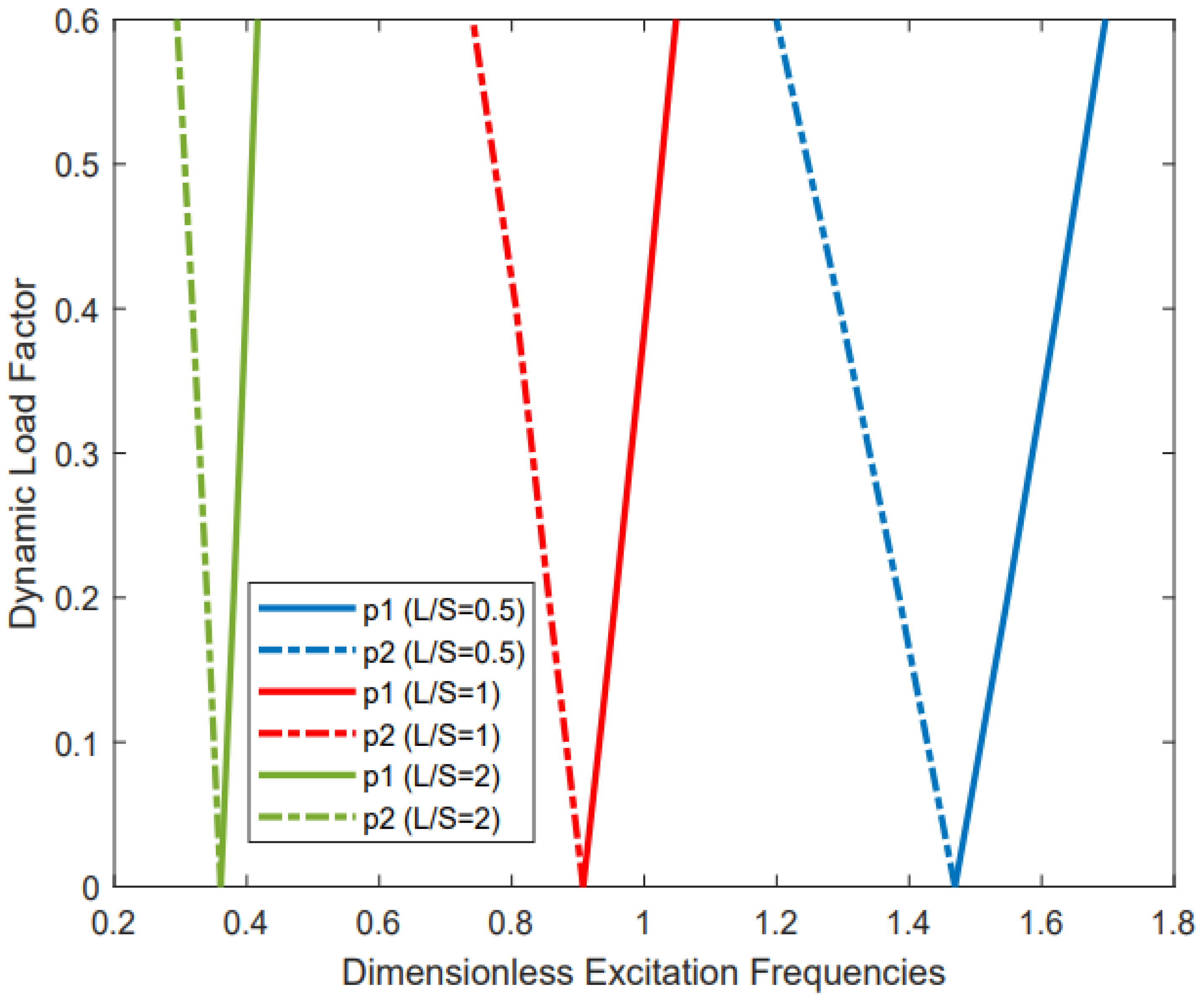
3.2.6. The Effect of the L/S Ratio

Figure 8 displays the effect of the length-to-circumferential ratio on the dimensionless excitation frequencies with various dynamic load factors. The panel characteristics are e 0 = 0.4, N 01 = 0.1, m = n = 1, and the values of the length-to-circumferential ratio are 0.5, 1, and 2. The results show that when the size of the length increases, the origin point of dimensionless excitation frequency decreases, the influence of axial dynamic load on the structure decreases significantly, and the width of the instability region decreases. It is observed that the excitation frequency is more sensitive to a change in length. When the panel is shorter, the onset of the instability region shifts to the right.

3.2.7. The Effect of the Circumferential Wave Number

Table 4 shows the effect of the circumferential wave number with an angle on the instability of the cylindrical panel. The excitation frequency increases as the circumferential wave number (n) increases for the smallest angle of the panel, (i.e., 30°), but for the largest angle of the panel, such as θ 0 = 100 ° , 180 ° , the excitation frequency decreases and then increases when the circumferential wave number increases. It is observable that the lower point of the instability region increases with the increase of porosity after a specific value of porosity coefficient, in fact, the reduction in stiffness and weight remains with the porosity increase, but at this value, this phenomenon happens because the average reduction in stiffness is significantly smaller than the cross-section inertia.

4. Conclusions

This study analyzed the parametric instability of simply supported functional graded porous cylindrical panels subjected to combined static and time-dependent periodic axial loads. The problem has been solved based on first-order shear deformation theory (FSDT) with Hamilton’s principle. The general equations are converted to ordinary differential equations by using superposition theory. Herein, the influences of different parameters on the instability of cylindrical panels have been examined, and the results are fully discussed. The theoretical approach was validated compared to other studies.
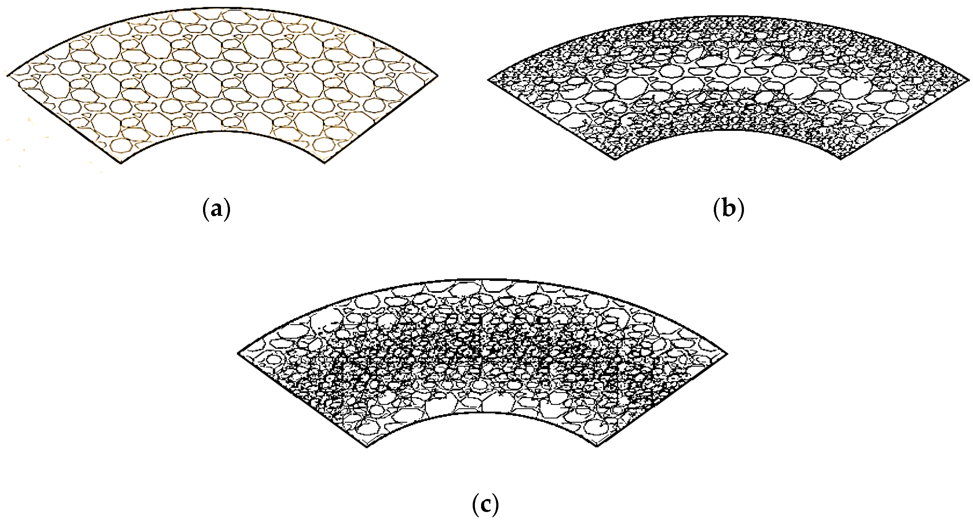
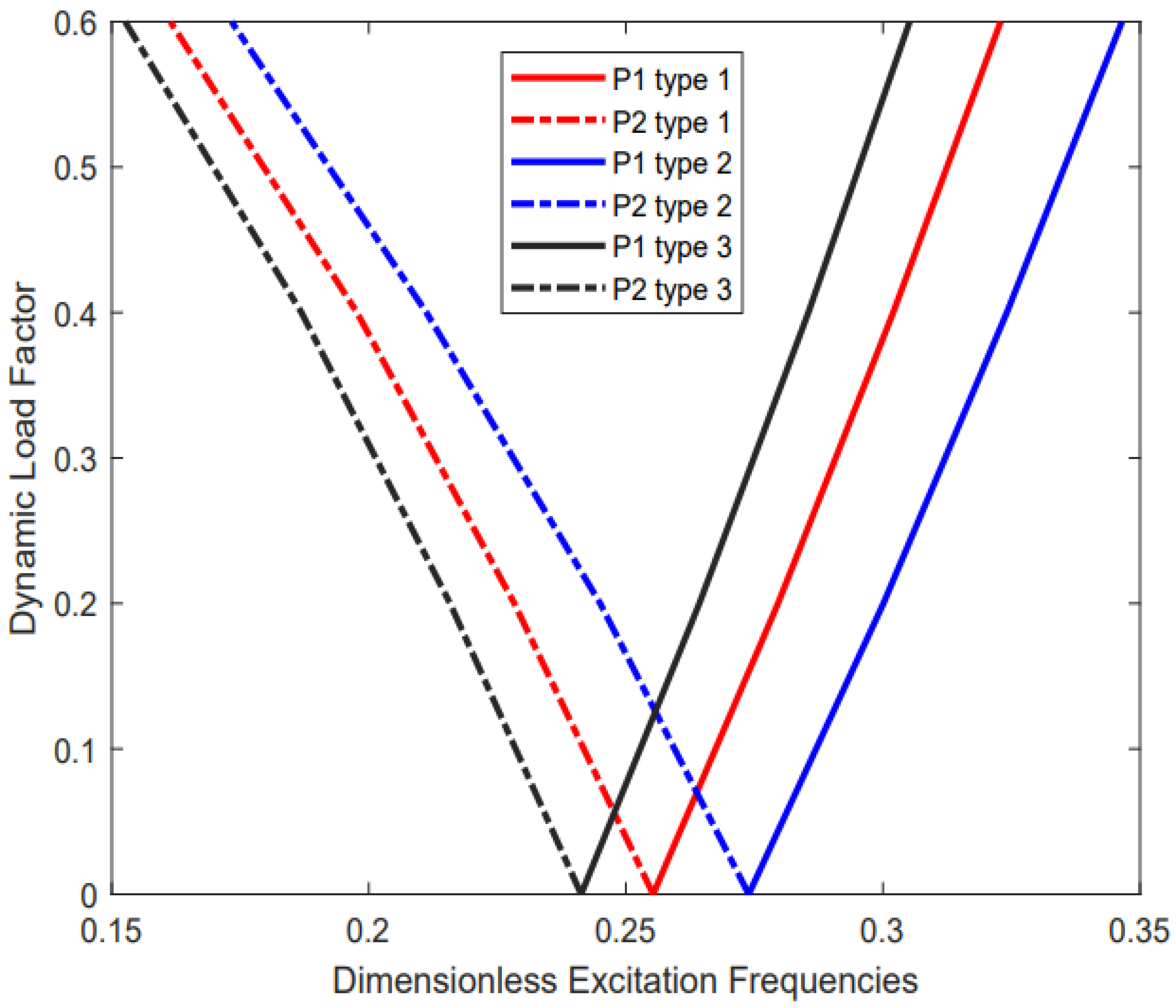
  • According to the results shown, it may be concluded that the symmetric porosity distribution around the midplane (i.e., Type 2) has more stiffness and results in the excitation frequency shifting forward to a high value, so it is preferred over the rest of the types.
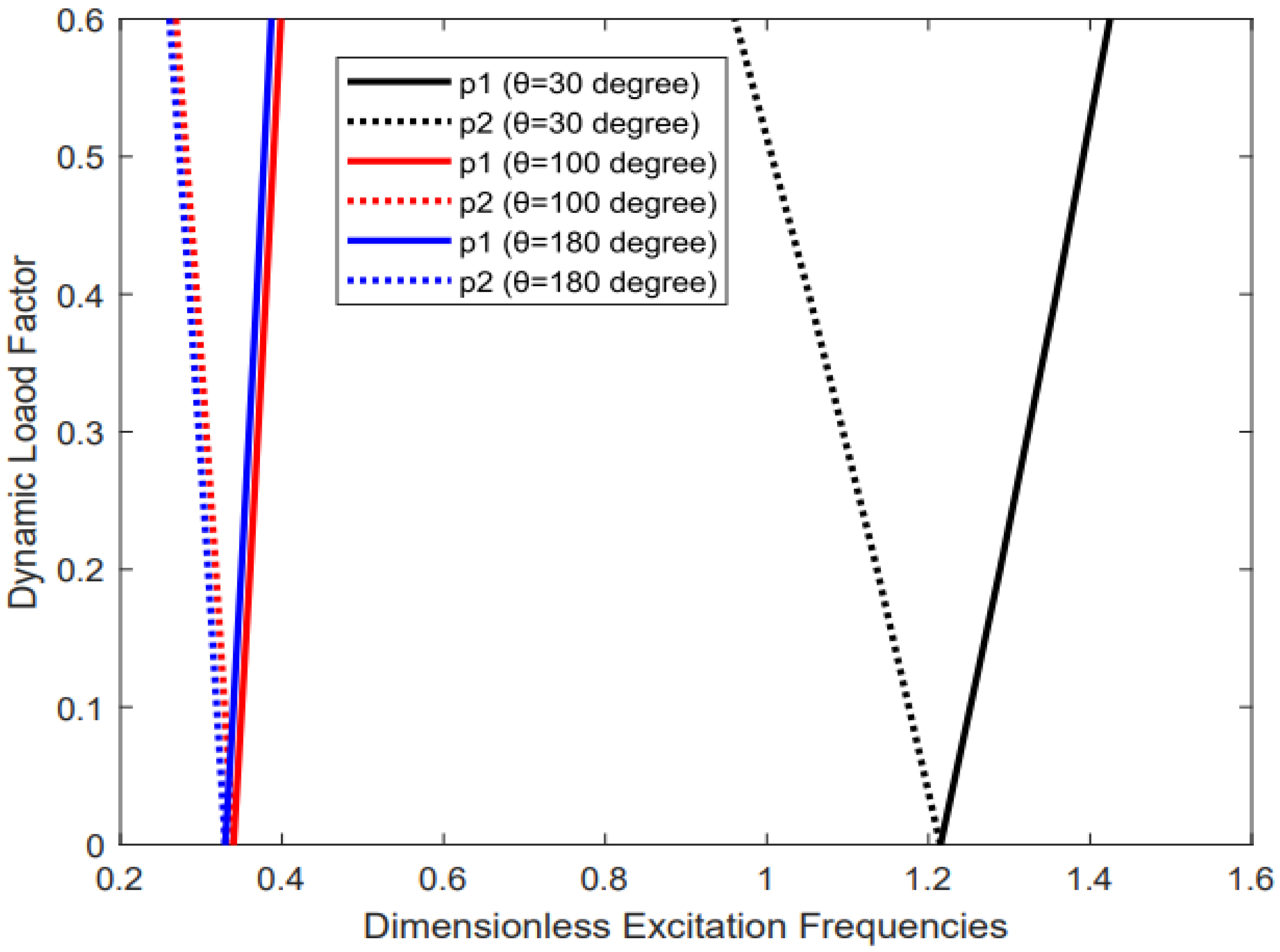
  • A small angle (i.e., θ 0 = 30 ° ) of the panel results in a large excitation frequency, but it is more influenced by the dynamic load. This behavior is fully reversed when the angle of the panel is large.
  • By increasing the circumferential wave number, the excitation frequencies decrease and then increase when the angle of the panel is large (i.e., θ 0 = 100 ° , 180 ° ), but when the angle of the panel is small (i.e., θ 0 = 30 ° ) the excitation frequencies increase by increasing the circumferential wave number.
  • The excitation frequencies increase when the static load factor decreases. Additionally, the width of instability increases as the static load factor and dynamic load factor increase.
  • The structure is less stable when it has porosity, and the weakness of the structure increases with an increase in the porosity.
  • For design purposes, care should be taken to decide the values of the static load factor and the porosity coefficient because a wrong selection leads to instability and then an early failure in the structure.
  • The dimensionless excitation frequencies and width of the instability region have a large value when the thickness is large and when the length is small.

Author Contributions

S.M.Z.: research proposal, methodology, results, discussion, interpretation, writing original draft, conceptualization, and editing. H.M.H.: research proposal, review, editing. All authors have read and agreed to the published version of the manuscript.

Funding

This research received no external funding.

Data Availability Statement

Not applicable.

Conflicts of Interest

The authors declare no conflict of interest.

Appendix A

Γ i , j   ( i , j = 1 , 2 , 3 , 4 , 5 ) are parameters and given by:
Γ 11 = ( I 10 α 2 + I 30 β 2 R 2 ) ,     Γ 12 = I 20 β R α + I 30 β R α ,     Γ 13 = I 20 α R ,     Γ 14 = ( I 11 α 2 + I 31 β 2 R 2 ) , Γ 15 = ( I 21 + I 31 ) β R α ,     Γ 21 = Γ 12 ,     Γ 22 = ( I 30 α 2 + I 10 β 2 R 2 + k I 30 1 R 2 ) ,     Γ 23 = ( ( I 10 + k I 30 ) 1 R 2 ) β Γ 24 = ( I 21 + I 31 ) β R α ,     Γ 25 = ( I 31 α 2 + I 11 β 2 R 2 k I 30 1 R 2 ) ,     Γ 31 = Γ 13 ,     Γ 32 = Γ 23 Γ 33 = ( I 10 1 R 2 + k I 30 ( β 2 R 2 + α 2 ) ) ,     Γ 34 = ( I 21 1 R k I 30 ) α ,     Γ 35 = ( I 11 1 R 2 + k I 30 R ) β Γ 41 = Γ 14 ,     Γ 42 = Γ 24 ,     Γ 43 = Γ 34 ,     Γ 44 = ( I 12 α 2 + I 32 β 2 R 2 + k I 30 ) ,     Γ 45 = ( I 22 + I 32 ) β R α Γ 51 = Γ 15 ,     Γ 52 = Γ 25 ,     Γ 53 = Γ 35 ,     Γ 54 = Γ 45 ,     Γ 55 = ( I 32 α 2 + I 12 β 2 R 2 + k I 30 )

Appendix B

D , K , t , H are defined as:
D = 1 Γ 11 ( Γ 12 K + Γ 13 + Γ 14 t + Γ 15 H ) ,     K = a 1 + a 2 t + a 3 H ,     t = j 1 + j 2 H H = ( a 1 + a 2 j 1 ) ( Γ 11 Γ 52 Γ 51 Γ 12 ) + j 1 ( Γ 11 Γ 54 Γ 51 Γ 14 ) + ( Γ 11 Γ 53 Γ 51 Γ 13 ) ( a 3 + a 2 j 2 ) ( Γ 11 Γ 52 Γ 51 Γ 12 ) + j 2 ( Γ 11 Γ 54 Γ 51 Γ 14 ) + ( Γ 11 Γ 55 Γ 51 Γ 15 )
where
j 1 = a 1 ( Γ 11 Γ 42 Γ 41 Γ 12 ) + ( Γ 11 Γ 43 Γ 41 Γ 13 ) a 2 ( Γ 11 Γ 42 Γ 41 Γ 12 ) + ( Γ 11 Γ 44 Γ 41 Γ 14 ) ,     j 2 = a 3 ( Γ 11 Γ 42 Γ 41 Γ 12 ) + ( Γ 11 Γ 45 Γ 41 Γ 15 ) a 2 ( Γ 11 Γ 42 Γ 41 Γ 12 ) + ( Γ 11 Γ 44 Γ 41 Γ 14 ) a 1 = Γ 11 Γ 23 Γ 21 Γ 13 Γ 11 Γ 22 Γ 21 Γ 12 ,     a 2 = Γ 11 Γ 24 Γ 21 Γ 14 Γ 11 Γ 22 Γ 21 Γ 12 ,     a 3 = Γ 11 Γ 25 Γ 21 Γ 15 Γ 11 Γ 22 Γ 21 Γ 12

References

  1. Babaei, M.; Hajmohammad, M.H.; Asemi, K. Natural frequency and dynamic analyses of functionally graded saturated porous annular sector plate and cylindrical panel based on 3D elasticity. Aeros. Sci. Technol. 2020, 96, 105524. [Google Scholar] [CrossRef]
  2. Mirzaei, M.; Kiani, Y. Free vibration of functionally graded carbon nanotube reinforced composite cylindrical panels. Compos. Struct. 2016, 142, 45–56. [Google Scholar] [CrossRef]
  3. Li, H.; Pang, F.; Chen, H.; Du, Y. Vibration analysis of functionally graded porous cylindrical shell with arbitrary boundary restraints by using a semi analytical method. Compos. Part B Eng. 2019, 164, 249–264. [Google Scholar] [CrossRef]
  4. Chu, H.-N. Influence of Large Amplitudes on Flexural Vibrations of a Thin Circular Cylindrical Shell. J. Aerosp. Sci. 1961, 28, 602–609. [Google Scholar] [CrossRef]
  5. Bich, D.H.; Xuan Nguyen, N. Nonlinear vibration of functionally graded circular cylindrical shells based on improved Donnell equations. J. Sound Vib. 2012, 331, 5488–5501. [Google Scholar] [CrossRef]
  6. Quoc, T.H.; Tham, V.; Van Tu, T.M. Free Vibration of Stiffened Functionally Graded Porous Cylindrical Shell Under Various Boundary Conditions. In Modern Mechanics and Applications; Springer: Singapore, 2022; pp. 347–361. [Google Scholar]
  7. Wang, Y.; Wu, D. Free vibration of the functionally graded porous cylindrical shell using a sinusoidal shear deformation theory. Aerosp. Sci. Technol. 2017, 66, 83–91. [Google Scholar] [CrossRef]
  8. Dang, X.H.; Nguyen, V.L.; Tran, M.T.; Nguyen Thi, B. Free Vibration Characteristics of Rotating Functionally Graded Porous Circular Cylindrical Shells with Different Boundary Conditions. Iran J. Sci. Technol. Trans. Mech. Eng. 2020, 46, 167–183. [Google Scholar] [CrossRef]
  9. Liew, K.M.; Ng, T.Y.; Zhao, X.; Reddy, J.N. Harmonic reproducing kernel particle method for free vibration analysis of rotating cylindrical shells. Comput. Methods Appl. Mech. Eng. 2002, 191, 4141–4157. [Google Scholar] [CrossRef]
  10. Sun, S.; Chu, S.; Cao, D. Vibration characteristics of thin rotating cylindrical shells with various boundary conditions. J. Sound Vib. 2012, 331, 4170–4186. [Google Scholar] [CrossRef]
  11. Xiang, S.; Li, G.C.; Zhang, W.; Yang, M.S. Natural frequencies of rotating functionally graded cylindrical shells. Appl. Math. Mech. 2012, 33, 345–356. [Google Scholar] [CrossRef]
  12. Zohar, A.; Aboudi, J. The free vibrations of a thin circular finite rotating cylinder. Int. J. Mech. Sci. 1973, 15, 269–278. [Google Scholar] [CrossRef]
  13. Lam, K.Y.; Loy, C.T. Free Vibrations of a Rotating Multi-Layered Cylindrical Shell. Int. J. Solids Struct. 1995, 32, 647–663. [Google Scholar] [CrossRef]
  14. Sheng, G.G.; Wang, X. The non-linear vibrations of rotating functionally graded cylindrical shells. Nonlinear Dyn. 2017, 87, 1095–1109. [Google Scholar] [CrossRef]
  15. Hosseini-Hashemi, S.; Ilkhani, M.R.; Fadaee, M. Accurate natural frequencies and critical speeds of a rotating functionally graded moderately thick cylindrical shell. Int. J. Mech. Sci. 2013, 76, 9–20. [Google Scholar] [CrossRef]
  16. Soldatos, K.P. Hadjigeorgiou vthree-dimensional solution of the free vibration problem of homogeneous isotropic cylindrical shells and panels. J. Sound Vib. 1990, 137, 369–384. [Google Scholar] [CrossRef]
  17. Keleshteri, M.M.; Jelovica, J. Nonlinear vibration behavior of functionally graded porous cylindrical panels. Compos. Struct. 2020, 239, 112028. [Google Scholar] [CrossRef]
  18. Loy, C.T.; Lam, K.Y. Vibrations of Rotating Thin Cylindrical Panels. Appl. Acoust. 1995, 46, 327–343. [Google Scholar] [CrossRef]
  19. Xie, F.; Tang, J.; Wang, A.; Shuai, C.; Wang, Q. Free vibration of functionally graded carbon nanotube reinforced composite cylindrical panels with general elastic supports. Curved Layer. Struct. 2018, 5, 95–115. [Google Scholar] [CrossRef]
  20. Zhang, H.; Shi, D.; Wang, Q.; Qin, B. Free vibration of functionally graded parabolic and circular panels with general boundary conditions. Curved Layer. Struct. 2017, 4, 52–84. [Google Scholar] [CrossRef]
  21. Dong, Y.H.; Zhu, B.; Wang, Y.; Li, Y.H.; Yang, J. Nonlinear free vibration of graded graphene reinforced cylindrical shells: Effects of spinning motion and axial load. J. Sound Vib. 2018, 437, 79–96. [Google Scholar] [CrossRef]
  22. Li, X.; Li, Y.H.; Xie, T.F. Vibration characteristics of a rotating composite laminated cylindrical shell in subsonic air flow and hygrothermal environment. Int. J. Mech. Sci. 2019, 150, 356–368. [Google Scholar] [CrossRef]
  23. Liew, K.M.; Yang, J.; Wu, Y.F. Nonlinear vibration of a coating-FGM-substrate cylindrical panel subjected to a temperature gradient. Comput. Methods Appl. Mech. Eng. 2006, 195, 1007–1026. [Google Scholar] [CrossRef]
  24. Safar Pour, H.; Ghanbari, B.; Ghadiri, M. Buckling and free vibration analysis of high speed rotating carbon nanotube reinforced cylindrical piezoelectric shell. Appl. Math. Model 2019, 65, 428–442. [Google Scholar] [CrossRef]
  25. Chen, Y.; Jin, G.; Ye, T.; Lee, H. Three-dimensional vibration analysis of rotating pre-twisted cylindrical isotropic and functionally graded shell panels. J. Sound Vib. 2022, 517, 116581. [Google Scholar] [CrossRef]
  26. Chan, D.Q.; Van Hoan, P.; Trung, N.T.; Hoa, L.K.; Huan, D.T. Nonlinear buckling and post-buckling of imperfect FG porous sandwich cylindrical panels subjected to axial loading under various boundary conditions. Acta Mech. 2021, 232, 1163–1179. [Google Scholar] [CrossRef]
  27. NGT, Y.; Lam, K.Y.; Reddy, J.N. parametric resonance of a rotating cylindrical shell subjected to periodic axial loads. J. Sound Vib. 1998, 214, 513–529. [Google Scholar]
  28. Liew, K.M.; Hu, Y.G.; Ng, T.Y.; Zhao, X. Dynamic stability of rotating cylindrical shells subjected to periodic axial loads. Int. J. Solids Struct. 2006, 43, 7553–7570. [Google Scholar] [CrossRef]
  29. Dai, Q.; Cao, Q. Parametric instability of rotating cylindrical shells subjected to periodic axial loads. Int. J. Mech. Sci. 2018, 146–147, 1–8. [Google Scholar] [CrossRef]
  30. Heydarpour, Y. Malekzadeh Dynamic Stability of Rotating FG-CNTRC Cylindrical Shells under Combined Static and Periodic Axial Loads. Int. J. Struct. Stab. Dyn. 2018, 18, 1850151. [Google Scholar] [CrossRef]
  31. Han, Q.; Chu, F. Parametric resonance of truncated conical shells rotating at periodically varying angular speed. J. Sound Vib. 2014, 333, 2866–2884. [Google Scholar] [CrossRef]
  32. Li, X.; Du, C.C.; Li, Y.H. Parametric resonance of a FG cylindrical thin shell with periodic rotating angular speeds in thermal environment. Appl. Math. Model 2018, 59, 393–409. [Google Scholar] [CrossRef]
  33. Li, X.; Jiang, W.T.; Chen, X.C. Parametric Instability of Rotating Functionally Graded Graphene Reinforced Truncated Conical Shells Subjected to Both Mechanical and Thermal Loading Conditions. Int. J. Struct. Stab. Dyn. 2022, 22, 2250067. [Google Scholar] [CrossRef]
  34. Phu, K.; Van Bich, D.H.; Doan, L.X. Nonlinear Dynamic Stability of Variable Thickness FGM Cylindrical Shells Subjected to Mechanical Load. In Modern Mechanics and Applications; Springer: Singapore, 2022; pp. 506–521. [Google Scholar]
  35. Zhao, S.; Yang, Z.; Kitipornchai, S.; Yang, J. Dynamic instability of functionally graded porous arches reinforced by graphene platelets. Thin-Walled Struct. 2020, 147, 106491. [Google Scholar] [CrossRef]
  36. Han, Q.; Qin, Z.; Zhao, J.; Chu, F. Parametric instability of cylindrical thin shell with periodic rotating speeds. Int. J. Non-Linear Mech. 2013, 57, 201–207. [Google Scholar] [CrossRef]
  37. Pellicano, F.; Amabili, M. Stability and vibration of empty and fluid-filled circular cylindrical shells under static and periodic axial loads. Int. J. Solids Struct. 2003, 40, 3229–3251. [Google Scholar] [CrossRef]
  38. Ng, T.Y.; Lam, K.Y.; Liew, K.M.; Reddy, J.N. Dynamic stability analysis of functionally graded cylindrical shells under periodic axial loading. Int. J. Solids Struct. 2001, 38, 1295–1309. [Google Scholar] [CrossRef]
  39. Sofiyev, A.H.; Kuruoglu, N. Parametric instability of shear deformable sandwich cylindrical shells containing an FGM core under static and time dependent periodic axial loads. Int. J. Mech. Sci. 2015, 101–102, 114–123. [Google Scholar] [CrossRef]
  40. Sofiyev, A.H. Influences of shear stresses on the dynamic instability of exponentially graded sandwich cylindrical shells. Compos. Part B Eng. 2015, 77, 349–362. [Google Scholar] [CrossRef]
  41. Dong, Y.H.; Li, Y.H.; Chen, D.; Yang, J. Vibration characteristics of functionally graded graphene reinforced porous nanocomposite cylindrical shells with spinning motion. Compos. Part B Eng. 2018, 145, 1–13. [Google Scholar] [CrossRef]
Figure 1. Geometric of the cylindrical panel under static and dynamic loads.
Vibration 05 00033 g001
Figure 2. Types of porosity distributions. (a) Type 1; (b) Type 2; (c) Type 3.
Vibration 05 00033 g002
Figure 3. The effect of porosity distribution.
Vibration 05 00033 g003
Figure 4. The effect of the panel angle.
Vibration 05 00033 g004
Figure 5. The effect of the porosity coefficient.
Vibration 05 00033 g005
Figure 6. The effect of static load.
Vibration 05 00033 g006
Figure 7. The effect of the h/R ratio.
Vibration 05 00033 g007
Figure 8. The effect of the L/S ratio.
Vibration 05 00033 g008
Table 1. Comparison of the natural frequency of cylindrical panels.
h/b θ 0 (degree)Soldatos and Hadjigeorgiou [16]Present Study
0.1300.70010.6393
600.80960.7589
900.95740.9296
0.2301.20321.1158
601.19791.1462
901.21991.2143
0.3301.59471.4945
601.5281.4804
901.46991.4864
Table 2. Comparison of dimensionless excitation frequencies.
d = 0.5
(m,n)Nt1SofIiyev [39]KuruogluPresent Study
P1P2P1P2
(1,1)066.566.5567.42167.421
0.166.96466.13267.841266.9984
0.367.78665.2968.673666.1449
0.568.59864.43669.496165.2802
d = 2
(1,3)060.19660.57160.58860.966
0.160.19659.81960.58860.209
0.361.31459.05661.71462.453
0.562.04958.28459.44258.664
Table 3. Comparison of dimensionless excitation frequencies.
nPorosity CoefficientYuewu and Dafang [7]Present Study
101.24291.2465
0.21.21551.2191
0.41.18931.1931
0.61.16771.1718
0.81.16331.1682
401.22561.246
0.21.20061.2208
0.41.17721.1974
0.61.1591.1795
0.81.15911.1805
Table 4. The effect of the circumferential wave number.
θ (Degree)Porosity Coefficient(m,n) = (1,1)(m,n) = (1,2)(m,n) = (1,3)
p (Type 2)p (Type 2)p (Type 2)
300.11.1813.68087.594
0.31.17673.66657.542
0.51.17833.67267.526
0.71.19563.7257.591
0.91.26593.93657.954
1000.10.34610.33670.723
0.30.33490.33550.722
0.50.32350.34160.726
0.70.3130.36250.739
0.90.3103 0.787
1800.10.33680.12710.212
0.30.32530.12460.211
0.50.31340.12240.212
0.70.30210.12120.216
0.90.29780.12430.23
Publisher’s Note: MDPI stays neutral with regard to jurisdictional claims in published maps and institutional affiliations.

