1. Introduction
Traditionally, vibration isolation systems have widely been used in industry to provide protection for sensitive equipment from vibration transmitted from the environment. These include the utilization of isolation to control the natural frequency of the system (
). These provide superior isolation at high frequencies (above
but result in vibration amplification at frequencies below this cut-off. While a natural solution to this problem is to lower the natural frequency of a system by utilizing very flexible springs, these springs are still required to support the structure’s mass. As such, this results in large static deflections, which are often not physically realizable [
1].
Several nonlinear systems have been proposed to combat this trade-off. In particular, high static low dynamic stiffness (HSLD) systems, such as quasi zero stiffness (QZS) systems have been the focus of significant research. While there are several proposed mechanisms of achieving quasi zero stiffness [
2,
3,
4,
5,
6,
7], all methods use the principle of placing positive stiffness elements in parallel with negative stiffness elements. When tuned correctly, the superposition of the negative and positive elements can create a range of motion with nearly zero stiffness [
8].
QZS systems are well documented in the literature. Many single degree of freedom (SDOF) designs have been developed, analyzed, and tested [
2,
6,
9,
10,
11,
12,
13,
14,
15,
16,
17,
18]. For most common systems, parameters affecting the static and dynamic properties are well understood, including how to optimize them for the best possible performance [
8,
19].
Recently, QZS elements have also been included in multi degree-of-freedom cascade systems, but this is much less understood. Gatti et al. used analytical and numerical techniques to investigate a two-degree of freedom (2DOF) system composed of one linear oscillator and one QZS oscillator [
20]. The effects of the system parameters were investigated with a particular focus on the ability for the damping to create detached resonant curves. Lu et al. further investigated the properties of two different nonlinear 2DOF systems [
21,
22]. This included the investigation of force transmissibility for a system that included both linear and nonlinear elements in different combinations [
22]. Transmissibility, also called “transmission ratio,” is the ratio of the response motion to the ground motion and can be measured with respect to force or displacement. An approximate solution for both force and displacement transmissibility of a cascade 2DOF QZS system was presented and compared with exact numerical simulations [
21]. Wang et al. provided an approximate solution for the force transmissibility of three different 2DOF QZS systems, comparing the models for their ability to isolate vibrations using four criteria [
23].
Providing a slightly different type of analysis, Wang et al. [
24] used numerical simulations for a MDOF system representing a seat that includes a controlled QZS system in the top layer. The simulations demonstrated the ability of the system to decrease the peak acceleration of the rider [
24]. The paper focuses on the response of a QZS system to an impulse input rather than a harmonic excitation. It shows that the uncontrolled QZS system outperforms the linear system, but adding control provides the lowest peak acceleration while not exceeding the maximum stroke of the seat.
All of the above work in the MDOF nonlinear system with QZS was conducted using numerical and approximate solutions. To the authors’ knowledge, there has been no attempt in the available literature to study these systems experimentally and to verify these models. This is especially true for models where displacement transmissibility is the focus. Displacement transmissibility is of particular importance for applications, including attenuating whole-body vibrations (WBV) in vehicles [
25] and ground shock waves during earthquakes [
26]. Considering the potential superior performance of these systems theoretically demonstrated in the literature, as well as their potential low cost when compared to active and semi-active systems, it is important to investigate the feasibility of designing such a system in practice. This paper proposes a design of a compact two-layer HSLD system capable of holding substantial weight. For the purposes of this paper, substantial weight is defined as close to 50 kg while maintaining the minimal stoke of the device. The prototype will be evaluated for its ability to provide superior vibration suppression, particularly at low frequencies where linear systems are ineffective. Superior vibration isolation includes (1) minimizing the resonant frequency and maximizing the isolation zone, (2) minimizing the magnitude of amplification at resonance, and (3) maximizing the ability to isolate large frequencies greater than the cut-off frequency. The 2DOF system will be compared to a linear SDOF system, a single-layer HSLD system, and a 2DOF linear system. The paper uses both a numerical and analytical framework to investigate the effects of various parameters that affect the dynamics of the system. The prototype uses positive stiffness elements in parallel with negative stiffness elements to achieve the HSLD conditions, as is the typical design for many SDOF prototypes presented in the literature.
2. Displacement Transmissibility of a SDOF QZS System
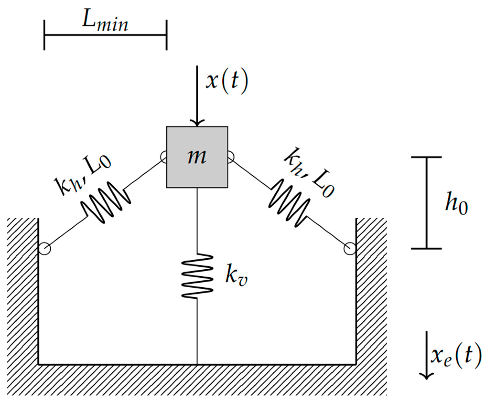
The simplest and most common form of the QZS system is constructed using oblique springs in parallel to positive stiffness elements, as shown in
Figure 1. This system is well understood within the literature. The reader is referred to the comprehensive analysis of the static properties of the system in the work of Alabuzhev et al. [
7] and Carrella et al. [
8], as well as their guidance on how to optimize the zero-stiffness condition. Carrella et al. [
27] and Brennan et al. [
28] investigated the dynamic properties of the system, while Xu et al. [
12] verified the theory of a SDOF system using experimental data. Carrella et al. [
29] showed through analytical and numerical techniques that force transmissibility and displacement transmissibility are not the same as they are for the linear system. The difference stems from the fact that transmissibility of the nonlinear system is directly dependent on the magnitude of the input force, and not displacement [
29]. Due to the comprehensive understanding of the SDOF QZS isolator within the literature, this paper will only give a brief overview of the approximate analytical solution for displacement transmissibility.
As was shown in the aforementioned papers, the exact equation of motion can be approximated using the Duffing equation, shown below.
where
.
is the displacement of the base motion, and
x is the displacement of the sprung mass.
,
,
, and
represent the mass, the damping, the linear stiffness component, and the nonlinear stiffness, respectively. This approximation is accurate while
[
29], where
. The stiffness elements can be approximated as follows [
29]:
where
and
represent the stiffness of the horizontal and vertical springs, respectively.
is the length of the springs when they are horizontal, while
is the original length of the springs under no-load conditions. Equation (1) can be written in non-dimensional form,
where
,
,
,
,
,
,
,
,
, and
.
The harmonic balance method (HMB) can be used to solve the nonlinear equations of motion [
30]. When a solution of
is assumed, the following relationships are obtained:
Within the solution, the terms containing
and
are ignored, as is typical while using the HBM [
30]. Squaring and combining these two equations and making use of the trigonometry identity
, the frequency–amplitude equation emerges as
Equation (7) is a simple quadratic equation in
and can therefore be solved quite easily, yielding the two branches of the amplitude–frequency curve. Using the amplitude–frequency relationship, the displacement transmissibility can be determined using the following relationship:
As mentioned previously, it is important to note that the transmissibility of the nonlinear system depends on the magnitude of the input force, unlike the linear case.
3. Displacement Transmissibility of a 2DOF QZS System
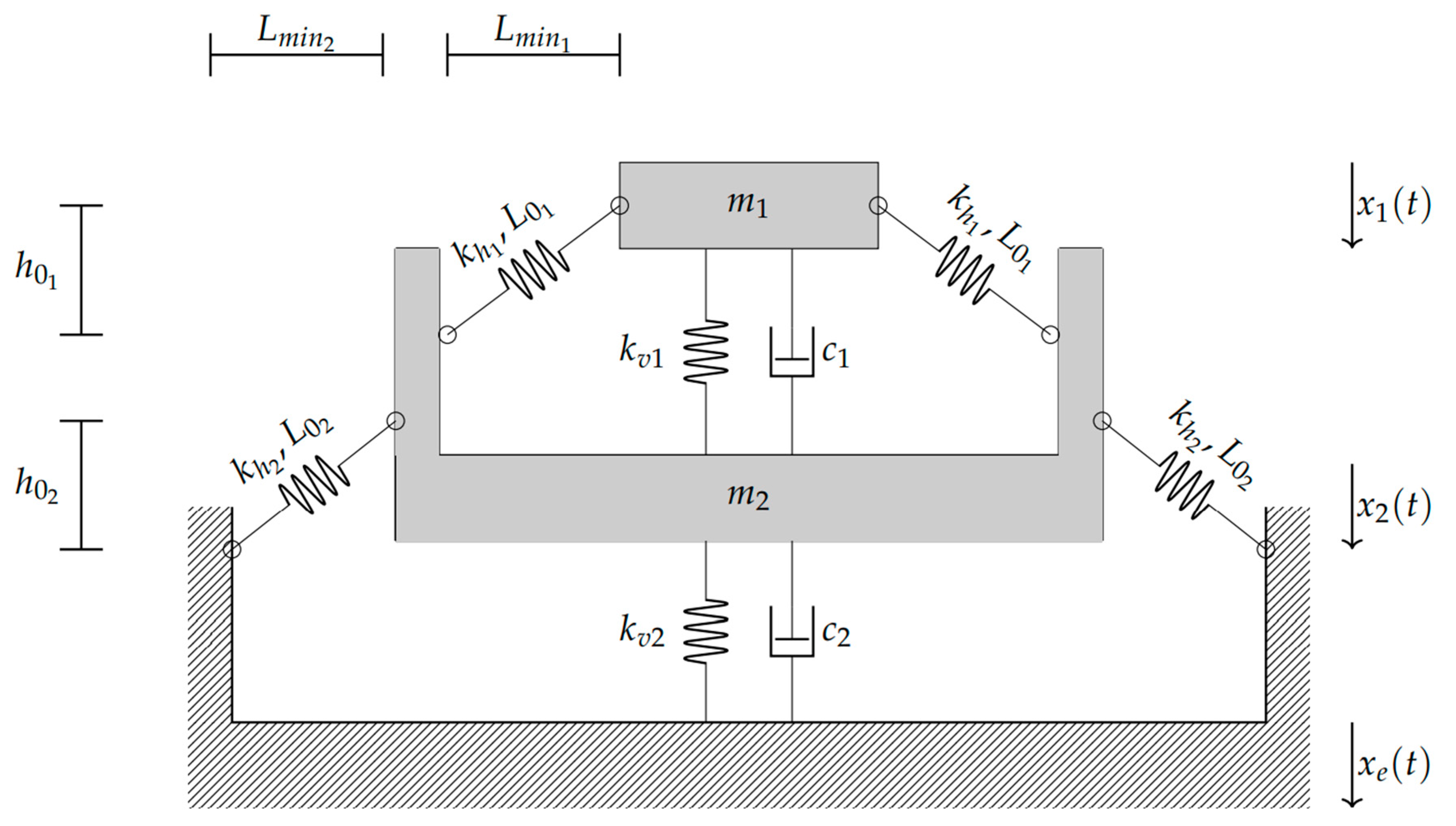
There are many ways to configure a 2DOF QZS system, each containing slightly different dynamics. Wang et al. compared three of these alternatives using force transmissibility and found that the model with the bottom nonlinear springs grounded works best across four different performance criteria [
23]. These criteria include minimizing peak dynamic displacement, minimizing peak transmissibility, and maximizing the sizes of both the unity and −40 dB isolation frequency bands [
23]. For this reason, and since the bottom-grounded model most closely matches the model of common multilayer structures such as buildings, the bottom-grounded model shown in
Figure 2 will be the focus of this paper.
When considering a displacement excitation frequency at the base of the system,
, the equations of motion can be written as follows:
where
,
,
,
,
is the input frequency, and
is time. This equation can be written in non-dimensional form as follows:
where
, and
,
,
,
,
, and
,
,
,
,
,
,
,
,
,
,
,
,
,
,
, and
.
While not dimensionless,
is defined throughout to be
, and
is defined as the distance
travels when the masses are placed on the springs and all the negative stiffness elements move to the neutral position. Assume a solution in the form of
Now ignoring the terms containing
and
, the harmonic balance method can be used to solve Equation (10), like the SDOF case. Unfortunately, the solution and associated parameters are more difficult to calculate algebraically. Instead, they are solved numerically using the open-source MATLAB
® library NLvib v1.3 [
31]. Finally, the displacement transmissibility is given by Equation (12).
4. Simulations
Simulations were conducted using two main methods. First, the approximate analytical method was implemented as described in the “Displacement transmissibility of a SDOF QZS system” and the “Displacement transmissibility of a 2DOF QZS system” sections above. For the SDOF case, the amplitude–frequency relationship and displacement transmissibility can both be calculated easily analytically. In the 2DOF case, the system is solved using a numerical approach, utilizing the harmonic balance method. This is carried out using the open source MATLAB
® library NLvib v1.3 [
31]. This library was integrated in the developed nonlinear dynamic model to solve the system response. In addition, the nonlinear equations of motion were simulated utilizing direct numerical integration employing a 4th order Runge–Kutta method. Unlike the harmonic balance method, where transmissibility curves are solved directly, the Runge–Kutta method obtains time series solutions, which are subsequently used to solve for the transmissibility curve. Each time series solution is run to steady state, at which point the magnitude of the peak amplitude is obtained. Where applicable, all models were verified using available data in the literature. The SDOF model was compared to the equations of Lu et al. [
22] and Carrella et al. [
29], while the 2DOF model was compared to those of Wang et al. [
23] and Lu et al. [
21].
A few attempts within the literature have presented a parametric study of MDOF HSLD stiffness systems [
21,
22,
23]. Most of these studies have focused on the effects of non-dimensional parameters on the force transmissibility plot of systems with very low damping and inconsistent input forces. While this is useful for gaining an overall understanding of the system, it makes it difficult to discern which parameters are important when designing and building HSLD stiffness systems. For example, Lu et al. [
21] provided a brief parametric study of the effects of
and
under very low damping
and an input amplitude that changes depending on the parameters used. While this is useful in some respects, when designing a system, it is useful to understand the sensitivity of changes in physical parameters on an individual basis, rather than changing two parameters at once. In addition, most practical systems have damping that is much greater than 1%, yielding transmissibility plots with much smaller peaks and hence different dynamics.
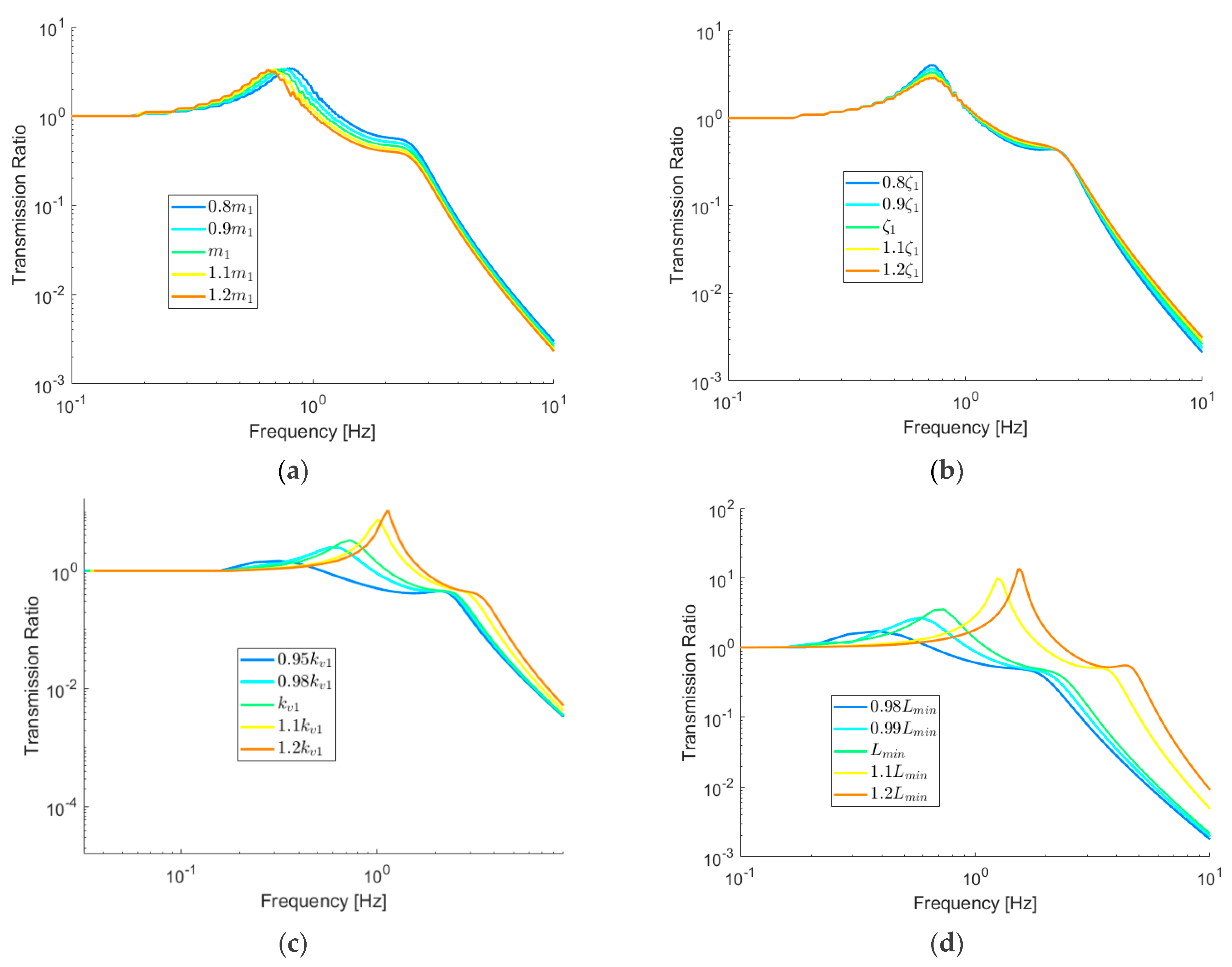
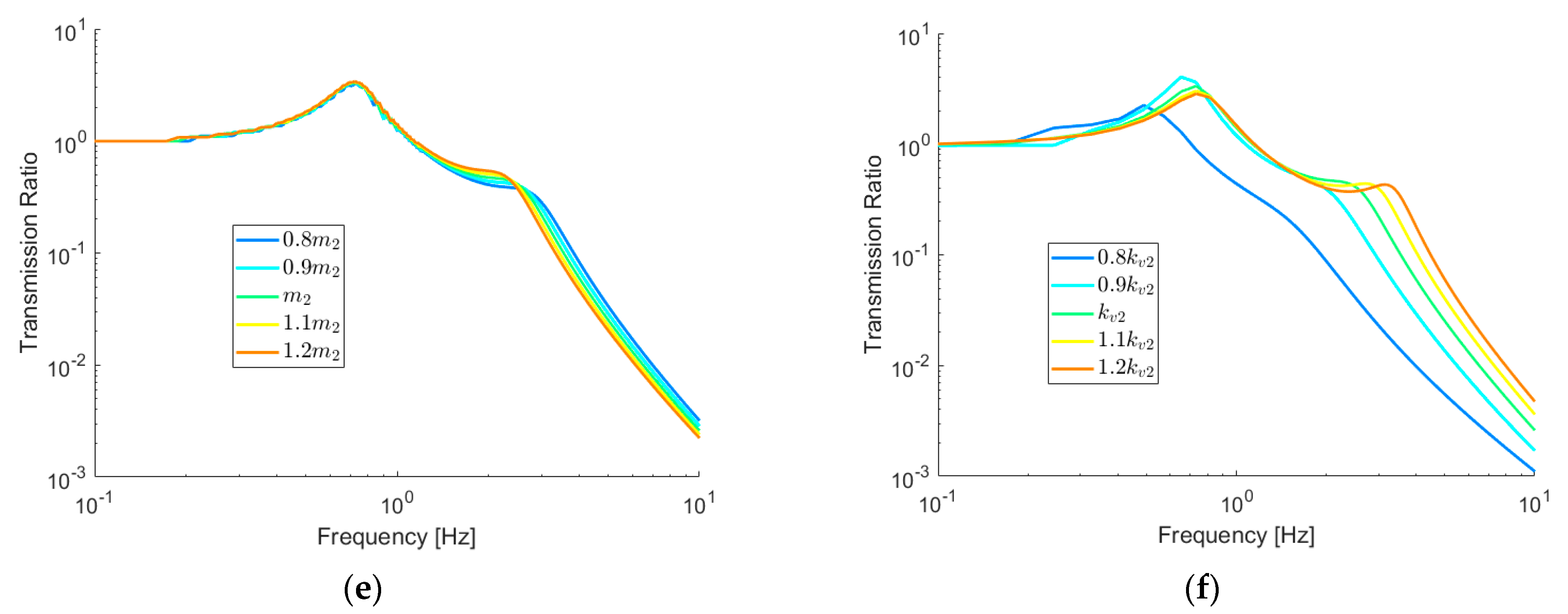
Figure 3 presents a sensitivity study for mass, damping, stiffness, and the geometrical parameters of the prototype developed within this paper. Where possible, while maintaining positive or zero stiffness,
,
,
,
,
and
are varied within ±20% from their nominal value. The nominal values used for the plots are shown in
Table 1. A plot showing the effects of changing
±20% is not shown because the effects are negligible. In all cases, the transmission ratio is defined to be between the ground and Mass 1.
Figure 3 shows that
and
have a negligible effect of the response of the system,
has a mild effect, and
,
and
each have a very profound affect. The stiffness and geometric parameters that influence the nonlinearity within the system and can therefore be utilized to reduce the localized stiffness. When the localized nonlinear stiffness approaches zero, the natural frequency of the response also approaches zero. For a system with localized positive HSLD stiffness, such as the system explored in this paper, there is incentive to reduce
or the vertical stiffness by a small amount to enhance the dynamic behavior of the overall system.
5. Experimental Investigation
To verify the principles explained in “Displacement transmissibility of a 2DOF QZS system” section, a 2DOF HSLD system was built as shown in
Figure 4. The model consists of two similar subsystems, separated by a mass placed between them. These two components will be referred to as Half 1 and Half 2 throughout the paper. The main purpose of the experimental portion of this study is to compare the dynamic response to the theoretical models, as well as further investigating the significance of the sensitivity analysis presented in the “Simulations” section. To test the dynamic response of the prototype, a Mikrolar R-3000 hexapod robot was used, as seen in
Figure 5. This robot can be programmed to provide complex, multi-axis motion to its platform. For the purposes of this paper, a simple vertical sinusoid of 2.5 mm amplitude (5 mm peak to peak) was utilized to investigate the vertical frequency response of the prototype. A frequency sweep was carried out from 0.5 Hz to 9 Hz, with 0.1 Hz step increments at the critical frequencies, and 0.5 Hz increments elsewhere. In the case of both the SDOF and 2DOF QZS system, the critical area is defined to be between 0.5 Hz and 3 Hz. For the linear SDOF system, the critical area is from 2.3 Hz to 4.5 Hz. While the frequency sweep was completed in the ascending and descending directions experimentally, no appreciable difference was observed in the results, and only the ascending results are displayed here. These results are expected for linear and nonlinear dynamic responses that do not contain a jump frequency.
Two triaxial accelerometers (Dalimar ceramic shear ICP® accel PCB model 356A17 tri-axial accelerometer) were placed on the platform of the hexapod robot and at the platform of Mass 1, respectively. One uniaxial accelerometer (Dalimar Modal array, ceramic shear ICP® accel PCB model 333B40) was placed on the platform of Mass 2. Since the motion was purely in the vertical direction, only the Z motion was captured for each accelerometer, and any X and Y accelerations were not analyzed.
Each layer of the 2DOF QZS system was built so that it could easily be reconfigured as a linear system by removing the oblique springs. This facilitates the investigation of behaviors of various combinations of linear and nonlinear systems.
The physical properties of the two individual halves of the system are summarized in
Table 1. The masses of
and
are estimated by summing the mass of any platforms and static components touching the masses, as well as half of the dynamic components associated with the mass. In the case of
, this includes the masses at the top of the 2DOF structure, the platform directly underneath them, and half the mass of the dynamic components associated with
and
. For
it includes the mass in the center of the two halves, both the platforms sandwiching it, as well as half the upper and lower dynamic components. While completing each test, the tuned amount of mass was placed onto the system such that each SDOF rested at the QZS condition during static equilibrium.
Stiffness elements were tested using a tensile testing machine (Instron Model 5969). Within each half of the 2DOF QZS prototype, there are 5 vertical springs and 16 oblique springs. In the case of the vertical springs, the Instron was used to test the overall stiffness of all five vertical springs placed in parallel within each half. All oblique springs were removed from the SDOF prototype, and the Instron was allowed to pass through the full range of motion of the device, while simultaneously measuring force and displacement. The force–displacement plot of Half 1 is displayed in
Figure 6. The tests were carried out at a rate of 10 cm/min, with a sampling rate of 10 Hz. As can be seen, the 5 parallel vertical conical springs are not perfectly linear. For displacements larger than 25 mm, the springs display a slight stiffening effect. This stiffening effect is attributed to the second layer of the coil spring contacting the base of the device.
Figure 6 fits two lines to these two portions of the plot separately. The slope of the latter part of the plot is used for the dynamic model of the HSLD system since this is where the range of motion resides. The plots for Half 2 are not displayed but are summarized in
Table 1.
The horizontal springs were also tested using the Instron, and the results indicated they were very linear throughout their range motion. Each of the 32 springs contained in the 2DOF prototype was tested, and an average stiffness was calculated. Results are summarized in
Table 1.
Figure 7 shows a comparison between the predicted transmission ratio for the SDOF system and the experimental counterpart for both the linear and HSLD stiffness cases. The dynamic response of the prototype agrees well with both the approximate and the exact simulations. While the linear system displayed a very low damping ratio of 2.5%, the HSLD system contained slightly more damping, about 4%. These slight differences are attributed to the additional damping in the 16 oblique springs, each of which was fitted with an axial guide to ensure only axial spring deformation. The addition of these springs along with their axial guides in the form of sliding pins adds considerable damping due to friction between touching components. To prevent pinching and galling of the aluminum material during motion, the machining tolerances of the oblique spring-guide rods and the blocks containing them were designed to be forgiving. However, under high stress, these tolerances lead to increased damping. In addition to this, bulging of the oblique springs on their respective spring guides also adds damping to the system.
Next, two halves of the model were put together to create the 2DOF system. These subsystems are designed to be like-for-like with the SDOF previously tested. The exception to this is that Half 2 contains additional static deflection on the vertical springs to account for the additional mass it bears. The MODF system was tested dynamically from 0.5–9 Hz. The transmissibility plot is shown in
Figure 8. Once again, there is good agreement between the numerical, analytical, and experimental data, with some noise and discrepancy introduced within the isolation zone. While the log plot amplifies the perceived error at large frequencies, the error between 1 and 3 Hz is large enough that it cannot be purely attributed to measurement error. In this region, the larger-than-predicted experimental transmissibility is due to one or more unmodeled vibration modes within the system. Since the four sets of spring guides for the oblique springs had small machining variations between them, friction varied slightly at each of the four sides of the device. This introduced a small amount of rotational movement into the system besides the vertical linear motion. This unmodeled vibration mode was most pronounced (resonated) around 2–3 Hz, causing the mathematical model to under-predict the transmissibility in this region. While the vibration mode described here was the most pronounced and easiest to see visually, it is possible that other modes were also present, such as rotations in different orientations.
6. Discussion
The purpose of this paper is to investigate the feasibility of incorporating MDOF HSLD stiffness systems into practical applications. The literature presents the theoretical idea as a very effective, cost-friendly approach for attenuating vibrations across the frequency spectrum. Several studies have shown superior theoretical performance of these systems that exceed the capabilities of linear and SDOF QZS systems [
21,
22,
23,
32]. However, the literature lacks experimental validation of these systems, as well as an understanding of the sensitivity of the design parameters associated with them.
The experimental results of this paper support the theory of superior performance, suggesting that a 2-layer HSLD stiffness system is able to outperform both linear and SDOF HSLD systems. This can clearly be seen in
Figure 8, where the 2DOF nonlinear system has a better dynamic response than all other systems using the three performance criteria. The first criterion is the ability of the device to decrease the resonant frequency and increase the size of the isolation region.
Figure 8 shows that additional layers of nonlinear elements decrease the frequency at which resonance takes place. Comparing the worst to best case scenario, the isolation region changes from above 4.6 Hz for the SDOF linear system to above 1.1 Hz for the 2DOF nonlinear system. This is a reduction of the amplification region to about 25% of its original size. Of course, linear systems could theoretically achieve a lower frequency. However, there is a limit to how low the natural frequency can be tuned using a conventional isolation spring. For example, typical isolation applications use the industry practice of 0.5 to 1 inch static deflection, which can be translated to a natural frequency of 3.1–4.4 Hz. In extreme cases, a 2-inch static defection can be utilized to obtain a natural frequency of 2.2 Hz. This constitutes the practical limit of traditional isolation springs. However, with HSLD isolators,
or
can be tuned to a much lower natural frequency. For example, when
is reduced to only 95% of its nominal value, the natural frequency is reduced from 0.7 Hz to 0.2 Hz, as seen in
Figure 3.
The second performance criterion considers the ability of the device to decrease the magnitude of the peak resonance. In this respect, the two-layer HSLD isolator also performs better than all other systems. The peak transmissibility is decreased to 3.3, much smaller than the 5.0 of the SDOF HSLD system, the 8.9 of the linear SDOF system, and the 45.2 of the 2DOF linear systems. This is a reduction to 7.3% of the worst-case scenario. An even greater reduction in the peak response can be achieved by tuning to a lower value (95%). This 5% reduction results in an approximately 10-fold reduction in the peak amplitude.
Finally, using the third performance criterion, the ability of the device to attenuate high frequency vibrations, the two degree of freedom HSLD system also arguably provides the best attenuation. While there is a narrow frequency band between 2.2 and 3.2 Hz where the SDOF HSLD isolator provides better attenuation, the 2DOF nonlinear isolator always performs better than any linear systems within the isolation region and below 10 Hz. The system provides a faster rate of decay at large frequencies than both SDOF systems, though the linear 2DOF does decay faster than it does.
The value in the comparison presented here lies in the fact that the same system was simulated and tested in all different configurations. While there are slight differences in the damping ratio and vertical stiffness of the two halves of the device, their dynamics remain similar enough for an accurate comparison to be made. This provides a concrete comparison between systems with very similar properties and shows that the addition of nonlinear layers improves performance.
These results are consistent with what is observed theoretically within the literature. While comparing the force transmissibility of linear SDOF, SDOF QZS, linear 2DOF, and 2DOF QZS systems, Wang et al. found that the nonlinear 2DOF isolator has the largest isolation zone and the smallest peak force transmissibility [
23]. Deng et al. compared multi degree of freedom systems using displacement transmissibility, and found that the addition of more nonlinear layers increases vibration isolation at low and ultra-low frequencies [
33]. This is consistent with the experimental results of this paper, which showed the isolation region getting larger with the addition of a second nonlinear layer.
The sensitivity analysis in
Figure 3 indicates the HSLD systems are very sensitive to stiffness and geometrical properties. This is especially true for devices that are tuned to be close to the QZS condition, such as the prototype that was built for the current paper. In these systems, very small changes in the vertical stiffness or geometrical properties cause large changes in the dynamic response, especially while moving towards the QZS condition.
Figure 3d shows that a 2% reduction in the
Lmin value, or a 2% increase in
L0 drastically improves the frequency response, especially when evaluated by the first and second criteria. A 2% change equates to 1.38 mm in the value of
Lmin and 2.36 mm in the value of
L0 within the prototype that was built. Machining tolerances can easily exceed these limitations, suggesting the need to incorporate adjustability into a design. For instance, the free length of compression springs typically has a high tolerance associated with them, close to 3% [
34]. This suggests it is very difficult to make a design that can accurately meet a QZS without adjustability that can be tuned after assembly of the device.
A similar conclusion is obtained when considering the tolerances associated with spring stiffness.
Figure 3c shows a large sensitivity of the dynamic response to changes that are as small as −5% and +20%. These tolerances can easily be exceeded in practice. For instance, while all springs within this study were bought from the same manufacturer and from the same batch of parts, the intrinsic variability in the parts, as well as the slight nonlinearities present within individual springs, was enough to disrupt the behavior of the system. In the case of the vertical conical coil springs used in this prototype, Instron testing observed stiffness changes from about 19,260 N/kg to 23,010 N/kg for Half 2, as summarized in
Table 1. This is nearly a 20% change in stiffness throughout the range of motion. This can lead to the system’s behavior being wildly different than expected, as is shown in
Figure 3c. To overcome this uncertainly, geometric adjustability should be incorporated into the design that allows the system to return to its designed behavior using correct tuning.
Figure 3 indicates that the dynamic response of the HSLD system is much less sensitive to the mass placed onto the system. When
m1 is changed ±20%, there is very little change in the shape of the dynamic response of the device. Instead, the curve is shifted to the right or left due to a change in the natural frequency of the upper layer. In practice, these results must be interpreted with caution. The mathematical model assumes the system is always at the point of the lowest stiffness while at resting equilibrium. When the mass is changed, the preload of the vertical springs must be changed to accommodate this such that the system is at the point of lowest stiffness when in resting equilibrium. If the design of the system does not allow for this, the dynamic model of the system will change much more drastically then presented in
Figure 8. This condition is especially true of systems tuned to achieve near QZS. Due to the very low stiffness of the system at the designed equilibrium point, the system is in fact very sensitive to changes in mass. Small changes in mass will lead to large static deflections, causing a large amount of drift from the optimal point.
7. Conclusions
This paper presents a direct experimental comparison between similar SDOF linear, SDOF HSLD, and 2DOF HSLD stiffness systems using a reconfigurable isolator design. In each case, nonlinearity is introduced using oblique springs that are assembled to provide negative stiffness to the system. When placed in parallel with positive stiffness elements, the overall effect is a system with reduced dynamic stiffness that can be tuned to near zero stiffness (QZS). The results of dynamic testing of the prototype under the three mentioned configurations indicate that the predicted theoretical response closely matches the experimental data, as can be seen in
Figure 7 and
Figure 8. In addition to this, both the theoretical and experimental data indicate that additional nonlinear layers enable a system to have a better dynamic response than a SDOF or linear system. This is especially true when considering the location of the resonant frequency, the size of the isolation zone, and when considering the magnitude of the peak transmissibility. Considering these results, as well as the relative simplicity, low cost, and passive behavior, enables the HSLD stiffness isolator to be an attractive choice for providing low frequency vibration isolation. Depending on the application, adding a second layer may be well worth the additional cost and complexity.
A sensitivity analysis of the non-dimensional parameters reveals that a 2DOF HSLD system is very sensitive to the stiffness, mass, and geometry of the device. This is particularly true when the device is tuned to approach the QZS condition, where changes of less than 5% in the parameters can drastically change the dynamics for the better or worse. Due to this sensitivity, adjustability in the geometrical properties should be used to account for uncontrollable tolerances within the springs, allowing the system to be tuned post manufacturing. The 2DOF HSLD system is best suited for applications where the mass is well defined and not changing over time. If this is not the case, the preloads of the vertical springs need to be adjustable to ensure that the oblique springs remain horizontal under static equilibrium.


