1. Introduction
Stiffened panels are commonly used in mechanical and aeronautical engineering, as they offer an excellent compromise between weight and strength. They are required to be lightweight and at the same time resistant to significant loads, e.g., the airframe of an aircraft fuselage. Unfortunately, attaching stiffeners to a plain plate generally increases its radiation efficiency and, consequently, it might reduce its acoustic transmission loss. According to Heckl [
1] and Maidanik [
2], there are two main physical reasons to explain such dynamics. Firstly, when the wavelength of the bending wave is much larger than the distance between the stiffeners, the main effect of the stiffeners is to introduce orthotropy into the plate and to substantially increase the equivalent stiffness to mass ratio, which is the main parameter driving the coincidence frequency effect. Since the corresponding wavelength depends strongly on the direction of propagation and so does the critical frequency (frequency at which the acoustic wavelength matches the structural bending wavelength), the presence of the stiffeners shifts the coincidence effect to lower frequencies when compared to the plane plate, increasing its radiation efficiency [
1]. Secondly, when the wavelength of the bending wave is much smaller than the distance between the stiffeners, the stiffeners have the approximate acoustic effect of dividing the plate into smaller panels whose radiation efficiency is greater than the radiation efficiency of the whole unstiffened plate [
2]. What has been said has a general validity, that is, the increase in radiation efficiency is characteristic of any type of stiffened panel. However, the vibro-acoustic behaviour of such panels is also closely related to its average vibration level, which is certainly lower for a reinforced panel according to the geometrical characteristics of the stiffeners, so that the exact acoustic power transmission level requires a specifically designed analysis.
In order to ensure an adequate level of acoustic comfort, e.g., inside the passenger cabin of an aircraft, a correct characterisation of the vibro-acoustic behaviour of these panels is essential, to carry out an accurate design aimed at reducing the above-mentioned transmitted sound power levels. This characterisation is achieved through vibro-acoustic analysis using different numerical approaches, each applicable under certain conditions [
3].
The vibro-acoustic analysis of small panels can be performed, in the low-medium frequency range, with deterministic numerical methods, e.g., the Finite Element Method (FEM) [
4] and/or the Boundary Element Method (BEM) [
5]. The limits are due to:
The need to discretize the continuum and to accurately reproduce the acoustic/structural waves, which implies an exponential increase of the computational costs along with the increase of the size of the system to be analysed and of the maximum frequency investigated;
The great sensitivity of higher order modes to small variations of geometry, construction and material properties; modal overlap results in high variability of frequency response functions (FRFs) for the aforementioned variations [
6] (FEM/BEM computer programs used for calculating mode shapes and frequencies are rather inaccurate for the higher order modes);
The increase of modelling effort in relation to geometric details.
Therefore, at high frequencies, a detailed deterministic model may be very difficult to solve. In the high frequency range and for large structures, the prediction of the response should be tackled as a probabilistic problem. The high-frequency response of a population of nominally similar artefacts, where the individual members differ slightly in many details, may be described by an ensemble-average behaviour and a statistical estimation of the distribution of responses around this average. Thus, Statistical Energy Analysis (SEA) is born [
7,
8]. In particular, the focus here is on a specific property of the SEA analysis environment, developed and optimised to study structures with reinforcing elements, called
Ribbed. In the VAOne SW [
9], the formulation used for a ribbed panel is based on Kirchhoff–Love [
10,
11] or Mindlin–Reissner shell theory [
12,
13]. The vibro-acoustic properties of the ribbed panel are derived from vibrational modes; the mode shapes and the corresponding natural frequencies allow an analytical calculation of the panel’s modal density and radiation efficiency. Finally, heuristic rules are then used to find the properties of this panel.
In the mid-frequency range, neither FEM/BEM nor SEA methods are fully appropriate. However, the short wavelength (short compared to the system dimensions) response of the system is typically reverberant, while the long wavelength (long compared to the system dimensions) response is typically deterministic. Thus, the possible solution lies in considering the problem of predicting the ensemble average response of a system of coupled subsystems, some of which are defined precisely (modelled with deterministic methods), whereas some others are uncertain (modelled with statistical methods). This is the core of the Hybrid method, which incorporates the dynamic equilibrium and power balance equations, combining deterministic and statistical techniques [
14,
15].
The stiffened panels have geometric characteristics such that they can be defined as periodic structures. The term “periodic structures” indicates structures which exhibit characteristics that repeat periodically in one, two or three-dimensions. In other words, a periodic structure can be considered as an assemblage of identical elements, called cells, which are coupled to each other on all sides and corners.
A technique to analyse wave propagation in periodic structures is the Wave FEM (WFEM) approach [
16]. In particular, the waves are associated with values of phase lag between opposite edges of a single periodic cell and can be found as solutions of an eigenproblem. For a given phase lag, the eigensolutions are the frequencies where waves propagate, and the eigenvectors are the associated deformations of the structure. This can be used to reduce the size of the dynamic stiffness matrix, solve the dynamic problem with a lowered computational cost and extend the range of analysis frequencies. Thus, this method allows the use of an FE approach on large periodic structures also at high frequencies. However, the periodicity condition makes it impossible to correctly enforce the right boundary conditions (b.c.), making this method inapplicable in the low frequency range because of a high structure sensitivity to specific boundary conditions.
In the absence of experimental results, the possibility of accurate numerical models of stiffened panels is supported by a theoretical/numerical approach [
17], based on the receptance method. This model was employed to evaluate the airborne sound insulation (transmission loss) of simply supported flat panels with stringer attachments, subjected to a diffuse acoustic load.
The analytical solution for governing equations of unstiffened plates is obtained in a simple way for simply supported or clamped rectangular plates, or for combinations of such b.c. [
18]; for all the remaining b.c. a very complex approximate solution can be found in the literature [
19]. Therefore, numerical approaches, such as the
Rayleigh–Ritz method or FEM, are preferable. In the analytical model [
17], the simply supported boundary conditions along the plate edges results in the precise knowledge of the eigenfunctions and the corresponding eigenfrequencies. For plates with different boundary conditions, it is always possible to approximate the modal shapes with a set of beam modes and the corresponding natural frequencies using the
Rayleigh energy technique [
20].
The complete characterisation of the vibro-acoustic behaviour of a panel also requires knowledge of the vibrational levels. For this reason, the capability of the model is extended by introducing the mathematical interpretation of a diffuse acoustic field (DAF), which is necessary to evaluate the space-average mean vibration velocity [
21].
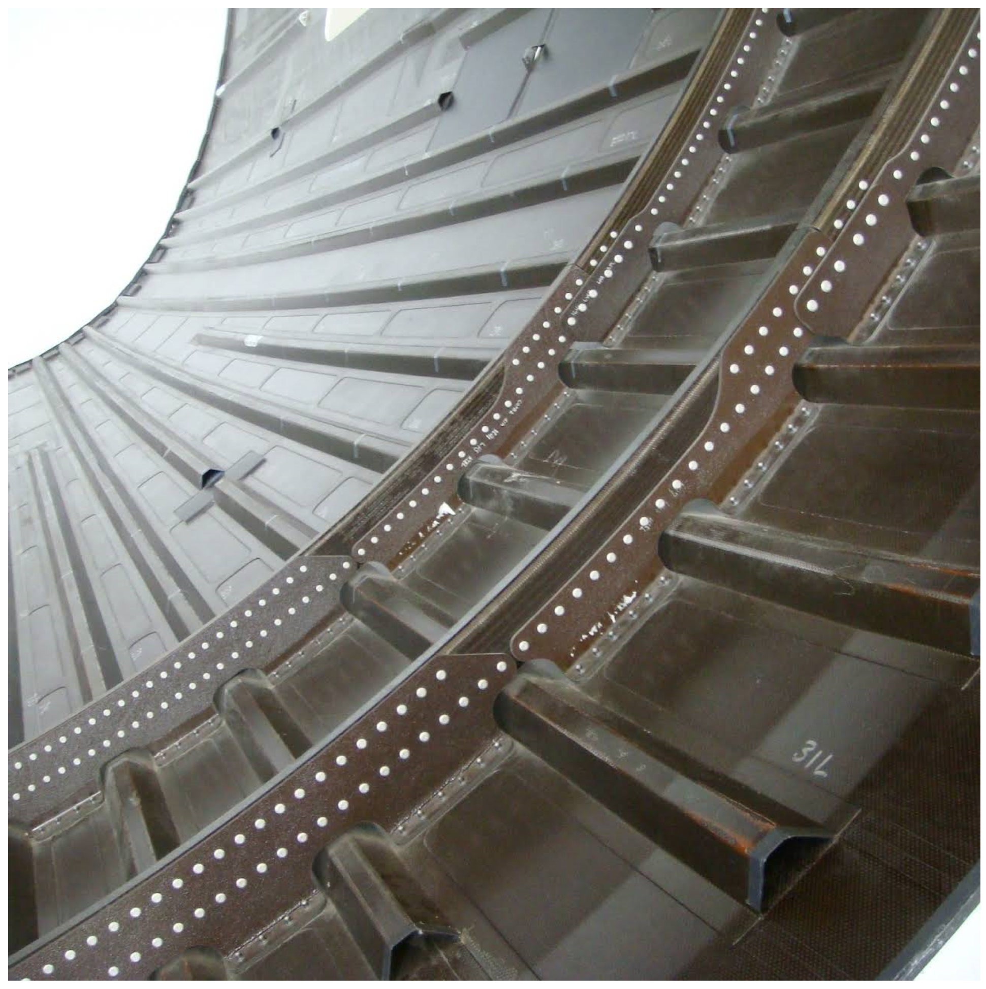
At this point, the necessary tools to understand the physics of sound transmission through panels with “unconventional” stiffeners (
Figure 1) are described, together with a criterion for the proper choice of the numerical method used for the different vibro-acoustic analyses. In fact, such stiffeners, unlike common compact stiffeners, are characterised by a very large cross-section in the transverse direction, with respect to the skin on which they are located; this results in dynamics that are difficult to predict by statistical approaches and, in general, by all those techniques based on the one-dimensional modelling of stringers.
The reduced computational costs and the straightforward and easy modelling requirement make the SEA Ribbed approach the only real solution for the evaluation of the TL and vibration levels in the high frequency range for large structures, as for the case of the airframe of an aircraft fuselage, composed by several reinforced panels. To this purpose, a procedure is proposed to extend the application of SEA Ribbed to unconventional stiffened panels while retaining the panel real dynamic behaviour. The idea is to evaluate the reinforced panel correct structural and acoustic dynamics through the most accurate approaches available in commercial codes, according to each code potentialities and limitations, and to assign these properties to an SEA Ribbed subsystem by properly adjusting its skin bending stiffness parameter, i.e., by calibrating a fictitious value for the shear modulus G. To this purpose, an optimisation process is set up to estimate the values of G as a function of frequency once the objective functions concerning the unconventional reinforced panel TL and average response have been evaluated through more sophisticated models.
2. Problem Description and Numerical Modelling Procedures
In order to correctly estimate the TL and space-average mean vibration velocity of stiffened panels, it is necessary to consider the appropriate requirements of each numerical approach. To this end, a description of the numerical modelling procedures for each method recalled in the previous section is hereafter presented. VAOne is the numerical code employed for all numerical analyses.
2.1. Fem Modelling Procedures—Low-Medium Modal Densities
The choice of FEM in the low frequency range is not only advantageous but also necessary in the light of the assumptions of the alternative approaches presented.
The first step is to create FE structural subsystems, which are used to represent the structural components in a vibro-acoustic model. There are no precise rules to be applied in the construction of FE subsystems. However, there are commonly used empirical guidelines:
Employ at least six (linear) elements for each propagation wavelength. The critical condition is at high frequencies, where the wavelength is minimal;
Avoid using a very fine mesh if not strictly necessary. Using many discretization elements increases the computational effort;
Use discretisation elements of regular geometry (mapped).
As shown in Reference [
22], the wave number of bending waves in homogeneous and isotropic plates is given by the present analytical equation:
where
E is the Young’s modulus,
is the Poisson’s ratio,
h is the plate thickness,
is the plate density and
f is the frequency.
If we consider the definition of wave number
and the possibility of writing the wavelength as a product of the number of discretization elements and their size (
), the minimum size of the discretization element as a function of plate properties and frequency is obtained:
The second step is to define:
The shell physical properties, i.e., fixing the type of FE subsystem (uniform plate, ribbed plate, etc.);
FE properties, i.e., defining the physical properties of the material associated to the subsystem;
The damping loss factor assigned to the FE subsystem.
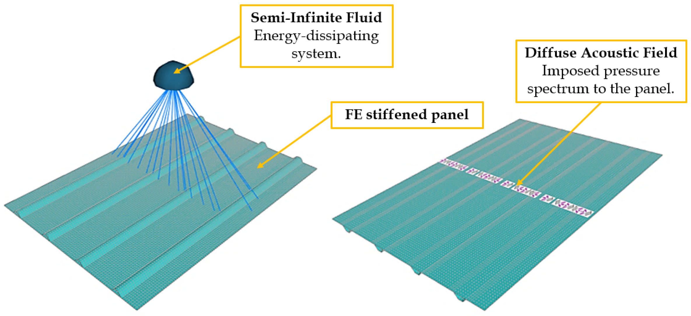
Once the structural FE subsystems have been realised, it is necessary to model the external fluid surrounding the structure in order to evaluate the TL. One possibility lies in the statistical representation of such fluid, considering an SEA acoustic cavity or an SEA semi-infinite fluid (SIF). In particular, the SIF represents, from a physical point of view, an unbounded exterior acoustic space where the acoustic waves radiated by a connected structural subsystem are not reflected back to the subsystem. From a conceptual point of view, it can be seen as an energy-dissipating sink.
The SIF should be connected to a coherent group of FE faces (not to the FE faces of the individual subsystems), this allows the SIF to interpret the radiation from the subsystems as correlated, i.e., the SIF will see a single radiated acoustic power relative to the FE face obtained by merging all those in the group.
The modelling phase ends with the application of the boundary conditions and the acoustic load (complete VAOne FEM model is shown in
Figure 2). It is worth mentioning that, in the low frequency range, the high sensitivity of acoustic response to stiffness distribution imposes a narrow-band analysis, with a modal basis extended to twice the maximum frequency of the analysis at least.
At this point the solver is able to extract the modal basis and the respective natural frequencies and subsequently evaluate the TL. More precisely, the power radiated by the entire structure is estimated by the SIF, while the power input (Equation (
3)) into the system is a function of the pressure load
p, the area
A on which it acts and fluid property (density
and speed of sound
), as shown in Reference [
9]:
whereas the space-average mean vibration velocity for the entire structural subsystem is estimated from knowledge of each section velocity and mass, through the estimate of the total energy which is weighted by the total mass of the FE subsystems.
2.2. Sea Ribbed Procedures—Large Modal Densities
At high frequencies and for large structures, a full deterministic model turns out to be very difficult to both realise and solve while a probabilistic approach is by far more advisable for handling a frequency response analysis. For this reason, in the subsequent sub-section, SEA modelling procedures employing the Ribbed subsystem option is described.
The development of an SEA Ribbed model is extremely simple, as neither mesh creation nor panel subdivision into different subsystems are necessary; only one single SEA subsystem needs to be defined having an adequate modal overlap factor (MOF). The complete characterisation of such a component is achieved by specifying:
The thickness and physical properties for the skin panel;
The ribs’ physical property;
The mean value of the spacing between the ribs;
The standard deviation about the mean value of the spacing between the ribs;
The offset of the rib centroid from the neutral axis of the underlying skin panel.
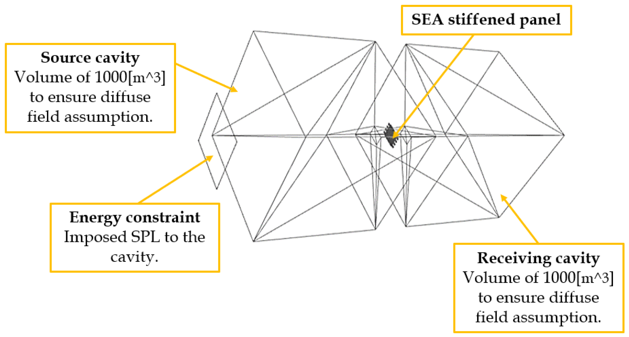
Differently from FEM, the estimate of the TL using statistical approaches is achieved by modelling the external surrounding fluid throughout a couple of SEA acoustic cavity subsystems (statistical volumes) reproducing a double room system of an experimental TL acoustic facility. To this aim, the panel whose transmission loss is to be calculated is located between a source reverberant environment (characterised by a fixed sound pressure level) and a reverberant receiver cavity, as shown in
Figure 3.
The input of energy from the source chamber to the panel and the acoustic emission of the latter into the receiving cavity is possible through either automatic or manual creation of area junctions, i.e., through the definition of energy exchange paths.
When the modelling phase is completed, the numerical simulation provides an estimate of the average sound pressure level (or energy) of the receiving cavity, due to all energy flow paths involved in the fluid–structure interaction. The estimate of an effective TL can be deduced from the following relationship [
9]:
where
A is the effective transmission area (junction areas),
is the acoustic wave velocity in the source cavity,
is the band centre frequency (in rad/s),
is the damping loss factor of the receiving cavity,
and
are the cavity energies and
and
are the modal densities of the cavities (in modes/(rad/s)).
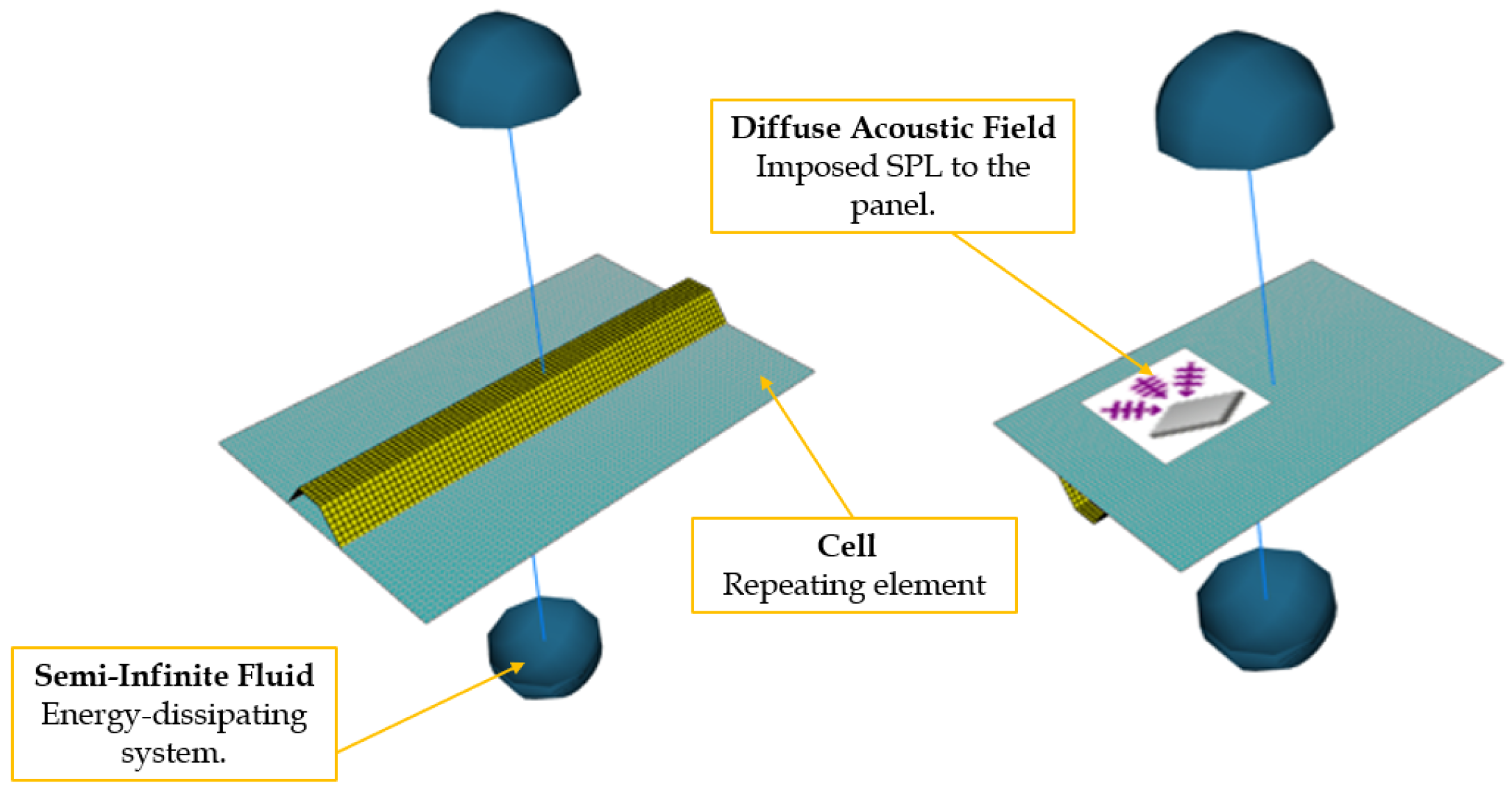
Theoretically, it would also be possible to extract the information on the space-average mean vibration velocity from the same model, however, in a typical reverberant chamber the blocked pressure is approximately 3 dB higher than the field pressure within the interior of the chamber [
23] when the acoustic wavelength is shorter than the object size.
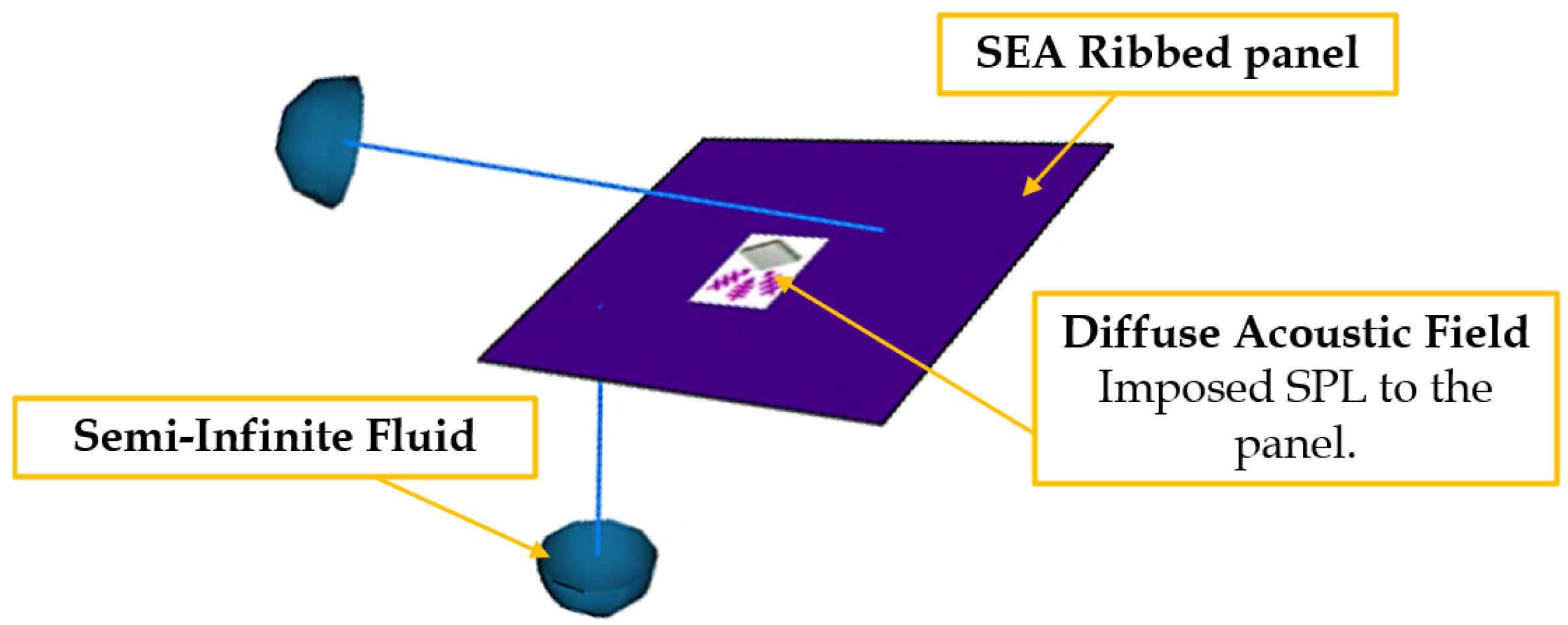
This causes an overestimation of the input power and consequently of the vibration levels. Therefore, there is a need for a further model (
Figure 4), created using the same technique adopted for an FEM model, i.e., applying a load and an SIF to the SEA Ribbed subsystem.
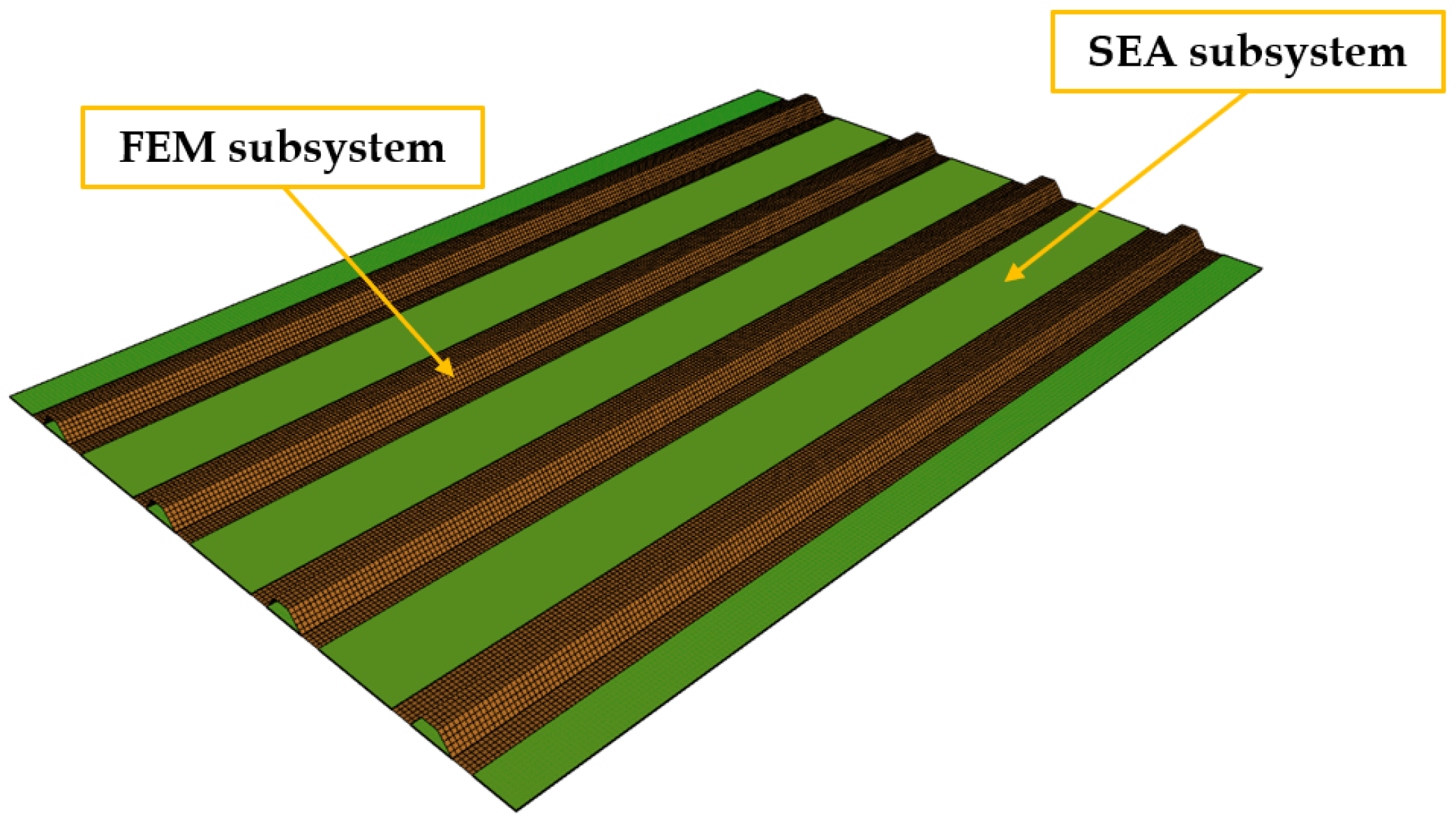
2.3. Hybrid Fe-Sea Procedures—Mixed Modal Densities
In the mid-frequency range, neither of the previous methods is entirely appropriate. The solution, as mentioned in the introduction, is to combine deterministic and statistical techniques to produce a Hybrid method.
The parts that behave deterministically (characterised by a low modal density) are modelled as FE subsystems, while parts that behave statistically (characterised by high modal density and statistical overlap) as SEA subsystems.
The procedures for creating these models (
Figure 5) are omitted as they are already proposed above. In fact, to realise the deterministic and statistical subsystems, it is necessary to follow the rules given for FEM and SEA respectively.
Similarly, to estimate TL and space-average mean vibration velocity it is necessary to follow the procedure proposed for SEA Ribbed modelling.
2.4. Wfem—Periodic Structures
Wave FEM (WFEM) is a technique for analysing the propagation of waves in periodic structures, i.e., structures that can be considered as an assembly of identical elements, called cells.
The realisation of WFEM models, shown in
Figure 6, consists of discretizing with FE the repetition cell, according to the same procedure and guidelines already mentioned for the FEM. However, more attention is required in the arrangement of the repeating element with respect to the cartesian axes and in the realisation of the mesh [
16]. Indeed, there should be a certain relative positioning between nodes of opposite edges. These considerations allow the periodicity condition to be applied correctly, thus reducing the degrees of freedom of the main problem.
3. Analytical Approach
The absence of experimental data required the use of an analytical approach [
17], based on receptance method, to support the development of accurate numerical models of stiffened panels. This approach is useful for assessing the transmission loss (TL) of simply supported flat panels with stringer attachments, subjected to a diffuse acoustic load (
5):
where
is the modal admittance,
is the modal radiation efficiency and
is a term that takes into account the stringers dynamics and their interaction with the skin.
The space-average mean vibration velocity can be formulated as in Reference [
21]:
where
represents the contribution of the mode (
m,
n) to the total velocity (
is an eigenfunction for the panel):
therefore, this contribution can be evaluated through knowledge of the modal force
(corresponding to external excitation) and
.
3.1. Space-Average Mean Vibration Velocity of a Plate Excited by a Daf
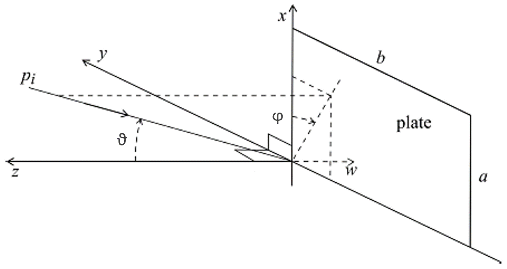
This derivation is based on the expression of the pressure field relative to a particular plane wave. Since a diffuse acoustic field (DAF) can be obtained by summing the effect of an infinite number of uncorrelated plane waves whose directions are equally spatially distributed [
24], the expression describing the vibrational components can be rewritten as:
where the
i-th component refers to one out of N incident plane waves, characterised by a polar angle
and azimuthal angle
(
Figure 7),
with
,
and
are the components along the reference axes of wave number
k:
,
and
.
The number of waves to be considered is the result of the trade-off between accuracy and computational effort. For this reason, a sensitivity analysis can be used to estimate this value.
3.2. Stringers Offset Adjustment
The theory behind the analytical model is developed from a set of assumptions. One, for example, consists of neglecting the mutual interaction between modes. However, according to some research [
25], it is legitimate to neglect the coupling terms between modes if the interest lies in the average responses, especially in the case where the fluid in contact with the structure has a low density compared to the structure (air).
The most restricting assumption considers the reinforcement element as placed symmetrically with respect to the middle plane of the skin. Actually, the stringers in real panels are placed entirely on one side of the skin, for example on the passenger cabin side in the case of the aircraft structures.
In order to better represent the real condition, a suitable increase of stringer inertial bending for the symmetrically modelled stringer is applied when the stringer is displaced on one side of the panel. The results obtained by increasing the stringer Inertial property on the basis on Equation (
10) (Huygens–Steiner theorem) was validated throughout FEM analyses from the panel, comparing the first bending modes of the real stiffened panel against those of the analytical panel with the shifted symmetric stiffeners.
In the above formulation, is the total bending inertia to be assigned to the analytical model to take account of the stinger offset, is the bending moment of inertia of the symmetric stringer (relative to its centroid), A is the section area, and d is the distance from the mid plate to the stringer centroid (the offset required to move the stringers symmetrically with respect to the skin and place it on a single side of the skin).
3.3. Generic Boundary Condition
The analytical solution for the governing plate equations is generally not obtainable for all combinations of boundary conditions. Therefore, the modal forms of rectangular plates can always be well approximated by a series of beam modes [
20]:
where
and
are beam mode shapes that satisfy the required boundary conditions and
are constants that can generally be derived using the
Rayleigh-Ritz procedure [
25].
The approximate solution for natural frequencies is instead developed using the
Rayleigh energy technique [
20]:
where
G,
H and
J are parameter functions of modal numbers
and boundary conditions, whose value is specified in Reference [
20].
is the flexural stiffness.
4. Numerical Techniques Results
In this section, the analytical model is used to support the development of accurate numerical models for vibro-acoustic analyses of conventional and non-conventional stiffened panels.
Some common features have been adopted for all examined models and procedures. Regardless of the type of panel, the skin is always simply supported, mounted in a rigid baffle and excited by a Diffuse Acoustic Field (DAF), which is characterised by a pressure spectrum with a unitary Power Spectral Density (1 PaHz) in all the examined frequency range.
The mechanical characteristics of the aluminium, used for the skin and the stiffeners, are shown in
Table 1:
The fluid used in the VAOne models to evaluate the transmitted sound power is air with a density of 1.21 kg/m and a speed of sound of 343 m/s.
All examined methods (FEM, WFEM and FE-SEA) support both stringer modelling options: one-dimensional (Beam) or two-dimensional (Shell) elements. The space-average mean vibration velocity is obtained from the power spectral density of the signal itself. More specifically, it corresponds to the square root of the PSD.
The analytical vibro-acoustic response is computed in the frequency band 0.5–16.000 Hz with a constant step, including all modes below twice the maximum frequency (32 kHz). To reduce the computational effort, the analysis is split by changing the step and modal base extension sizes according to the frequency range reported in
Table 2:
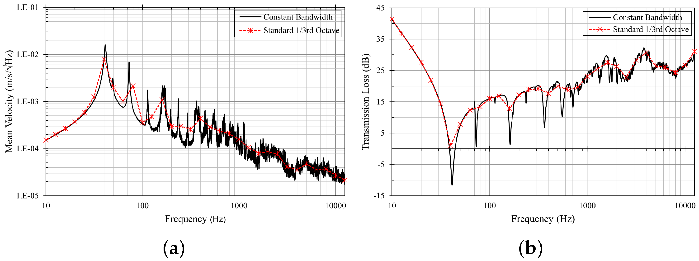
Constant narrow-band results are then converted to a third-octave band by performing an averaging operation; this step is fundamental, not only for greater graphical clarity, but also for consistent comparison with results obtained from statistical approaches. For this purpose, an additional routine is created to average the values of the variables within the band of interest.
To estimate the space-average mean vibration velocity corresponding to a particular band, it is necessary to estimate the average energy content in such band. Since energy is proportional to the square of the vibrational velocity, in the case of constant-band sampling, it is sufficient to sum the squares of the velocities in the desired band and divide by the corresponding number of samplings (
Figure 8a). With reference to the transmission loss, it is necessary to find an average value of the ratio of incident power to transmitted power (
Figure 8b).
In general, any deterministic model requires the setup of a narrow-band analysis.
4.1. Flat Panel with Symmetrical Conventional Stiffeners (Z-Section)
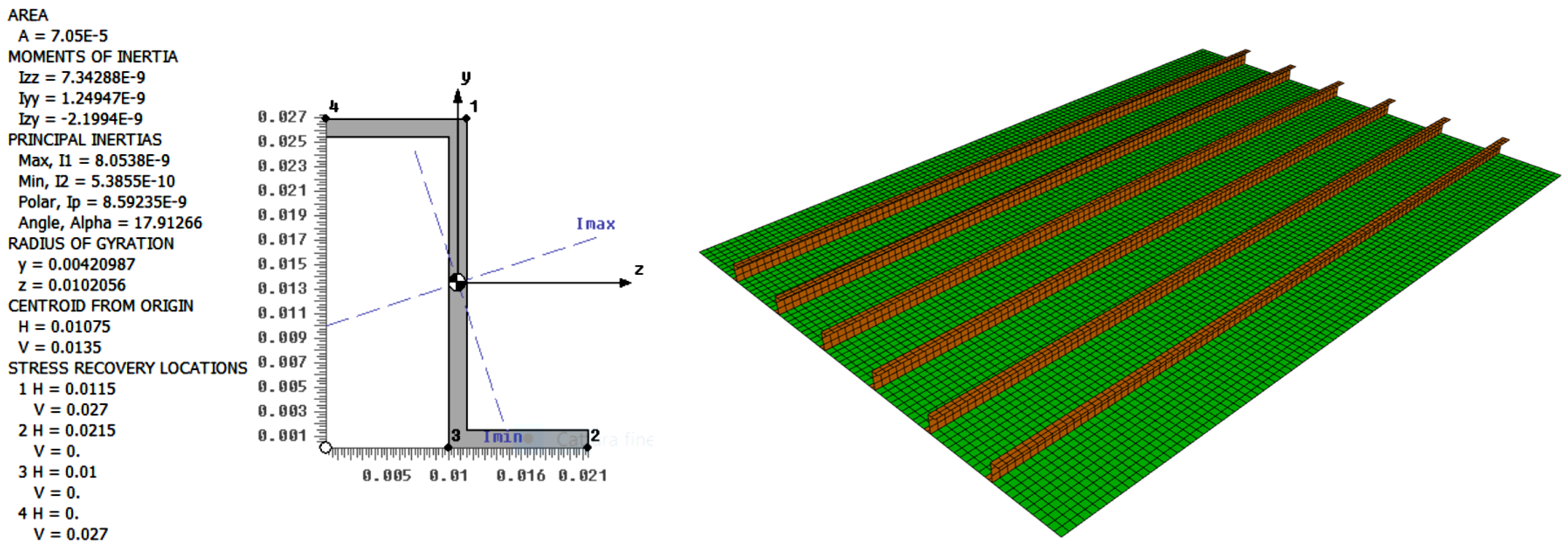
The skin of the stiffened panel used is an aluminium sheet with a thickness of 1.5 mm and in plane extension 700 × 1000 mm. The six stringers are beams with a Z cross-section positioned symmetrically with respect to the skin’s mid-plane (
Figure 9).
From Equation (
2), it is possible to estimate the dimension of the discretisation elements for FEM and WFEM models. In the former, the analysis is extended up to 2000 Hz (constant bandwidth of 2 Hz), making it necessary to ensure at least six elements per wavelength at 4000 Hz (modal base range). For the WFEM model, the analysis is extended up to 12.5 kHz (third-octave band) while the modal base is extended by default up to 2.2 times the maximum analysis frequency. These conditions, combined with the geometric and physical characteristics of the skin, result in a minimum FE size of 10 mm and 4 mm for FEM and WFEM models respectively. On the other hand, SEA models require a high modal density for the subsystems, or at least five modes per each examined band. In the case of the SEA Ribbed model, constituted by a single subsystem, a MOF
1 above 1000 Hz (
Figure 10a) is observed, whereas, in the case of the Hybrid model, constituted by several SEA subsystems (Plate), i.e., the parts of skin interposed between one stiffener and the other, an MOF
1 above 3000 Hz (
Figure 10b) is observed.
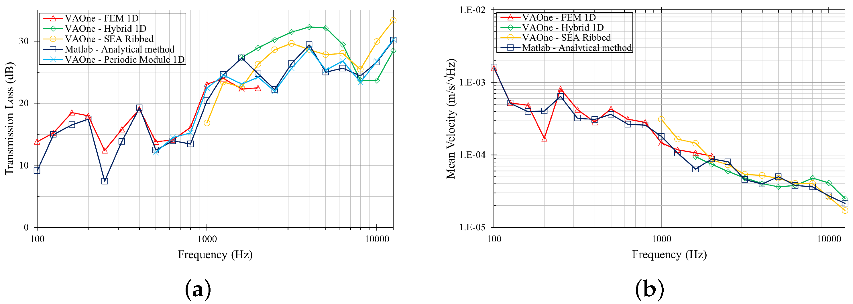
The vibro-acoustic responses, obtained from the different models, are plotted within the respective frequency validity range. Such results are regrouped according to the type of elements used to model the stringers: 1D FE (
Figure 11) or 2D FE (
Figure 12).
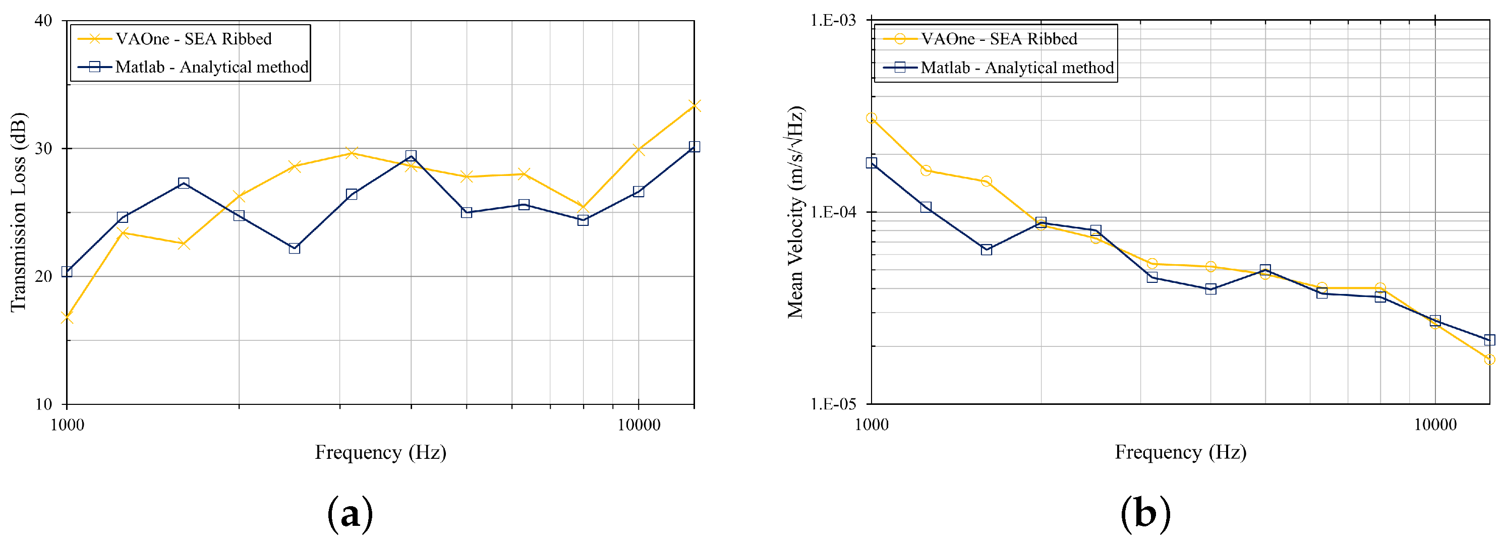
Considering only the models whose stiffeners are modelled with 1D elements (
Figure 11) and referring to the analytical TL and mean velocity (blue curve), it is possible to observe very good matching with both the FEM solution (red curve) in the low-medium frequency range and the WFEM solution (VAOne—Periodic Module/light-blue curve) in the medium/high frequency range. The small differences observed can be attributed to the simplifying assumptions of the analytical model.
The FE-SEA Hybrid model requires the skin to be modelled with statistical subsystems (SEA shell subsystems) for the parts interposed between two stiffeners, while the reinforcement, being very rigid, are modelled as FE subsystems. The size of the FEs constituting the stiffeners is accurately estimated through Equation (
2), while the MOF of the SEA subsystem used, shown in the (
Figure 10b), theoretically allows the use of such a model above 3000 [Hz].
Considering as a reference line that associated to the analytical approach (blue curve), the responses of FE-SEA Hybrid model (green curve) are characterised by a consistent trend of mean vibration velocity, whereas there is a constant overestimation of the TL under the critical frequency, as probably due to the small size of the physical SEA subsystems (parts of the skin interposed between two stiffeners).
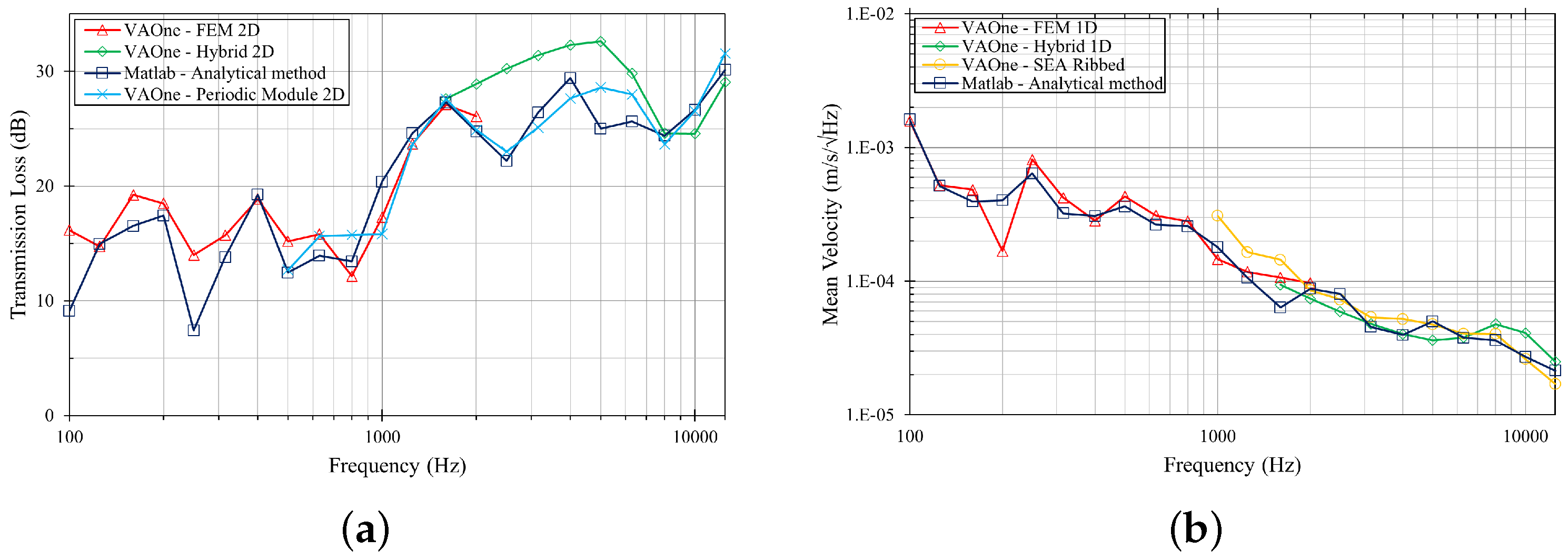
A similar consideration can be inferred for the models with 2D (
Figure 12) stiffeners.
It must be noted that, in the analytical model, the stiffener is described as a 1D beam element; the solution of this model is intentionally reported in both
Figure 11 and
Figure 12 in order to make possible an exhaustive comparison also with the vibro-acoustic responses of the models with 2D stiffeners. In conclusion it is possible to assert that there is no difference in the responses when modelling the stiffener by 1D or 2D elements, as long as stiff and compact stiffeners are employed, as for the examined case, and this is crucial for several reasons:
Using FE 1D reduces the effective number of degrees of freedom and consequently reduces the computational effort;
Using FE 1D simplifies the model development phase;
Corrected vibro-acoustic response estimates can be obtained from SEA Ribbed models.
4.2. Flat Panel with One-Side Conventional Stiffeners (Z-Section)
The skin of the stiffened panel used is an aluminium sheet with a thickness of 1.5 mm and in plane extension 700 × 1000 mm. The six stringers are beams with a Z cross-section positioned entirely on one side of the panel (
Figure 13).
Comparisons of the transmission loss and vibration levels, predicted by the different models, for a stiffened panel with conventional stiffeners placed entirely on one side of the skin, are shown in
Figure 14 and
Figure 15. Such a panel presents the same physical-geometric characteristics as the previous one; therefore, it is possible to refer to the subsection above for clarification on modelling and analysis procedures.
The responses obtained confirm the possibility of circumventing the drawbacks inherent the analytical solution that can only tackle stiffeners placed symmetrically with respect to the skin. The obtained results are useful for further strengthening the conclusions of
Section 4.1: for many conventional stiffeners, according to stiffener properties, it is possible and advantageous to model conventional stiffeners with one-dimensional beam-type elements.
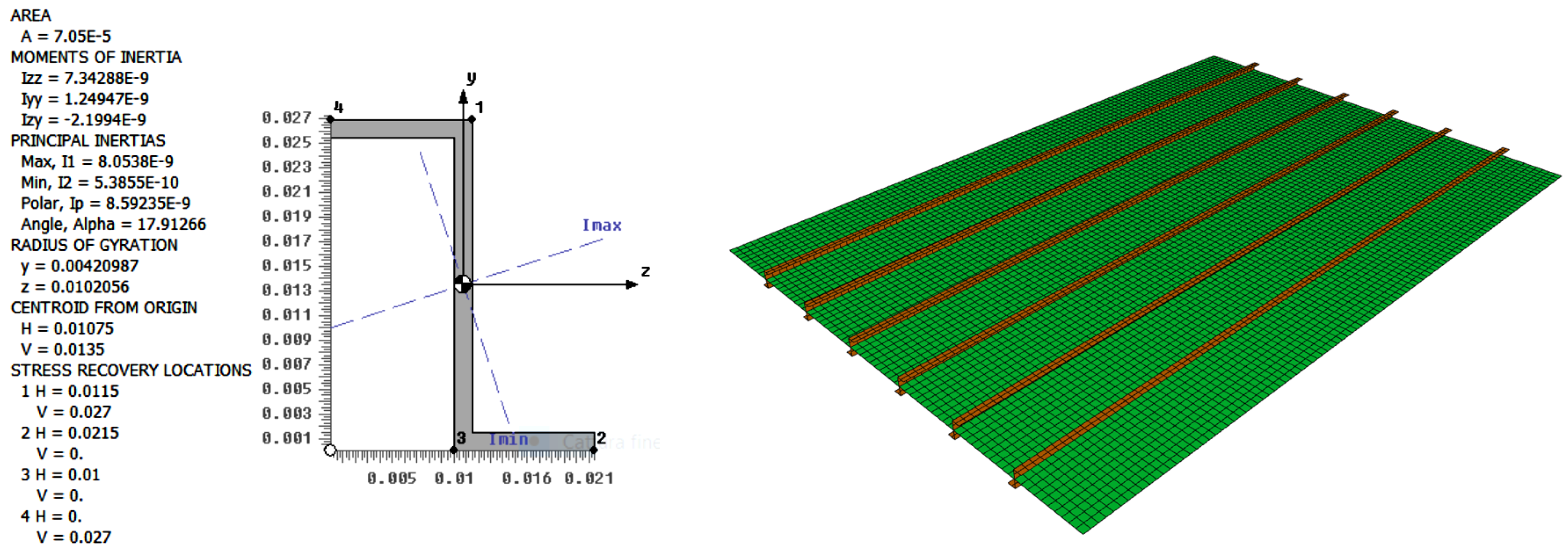
4.3. Flat Panel with One-Side Unconventional Stiffeners (Hat-Section)
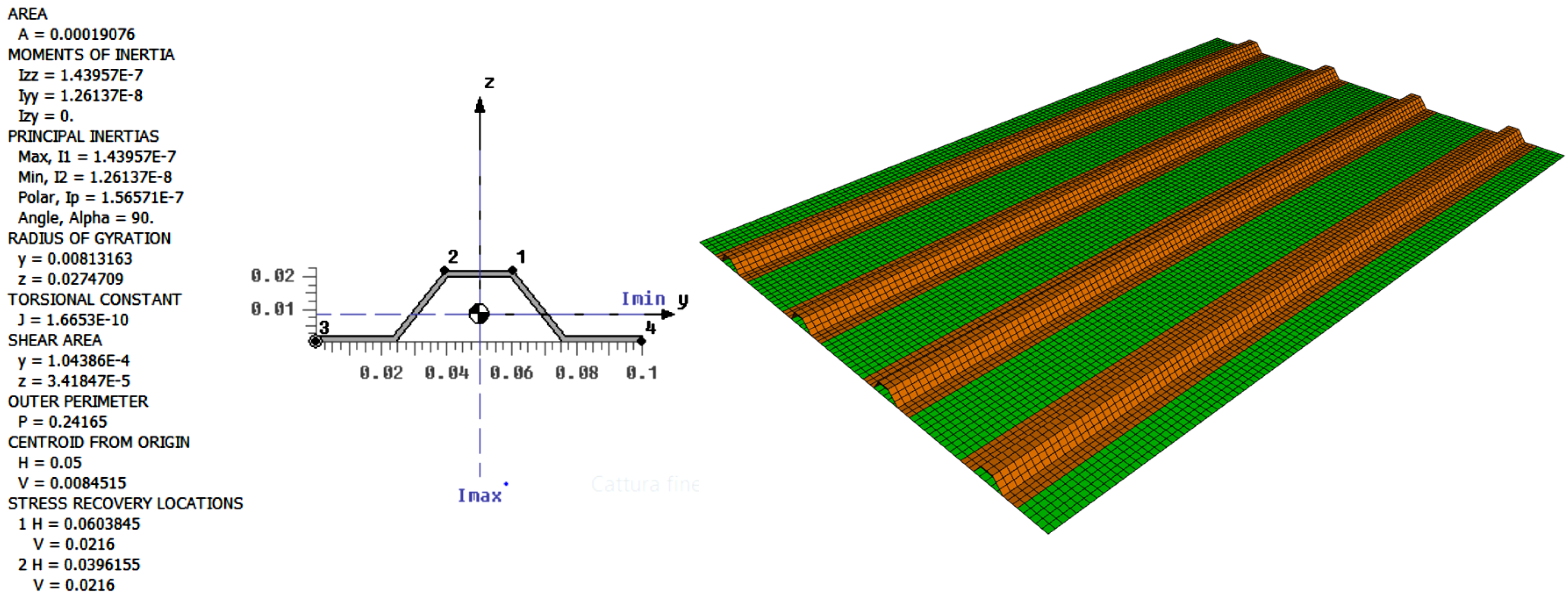
The skin of the stiffened panel used is an aluminium sheet with a thickness of 1.8 mm and in plane extension 800 × 1200 mm. The four stringers are beams with a Hat cross-section positioned entirely on one side of the panel (
Figure 16).
The FEM analysis is realised with a constant bandwidth of 2 Hz and is extended up to 2000 Hz, making it necessary to guarantee at least 6 elements per wavelength at 4000 Hz, while, for the WFEM model, the analysis is in third-octave band and is extended up to 10 kHz (the modal basis is extended by default up to 2.2 times the maximum analysis frequency). These conditions, combined with the geometric and physical characteristics of the skin, result in a minimum FE element size of 11 mm and 4.5 mm for the FEM and WFEM models, respectively.
For what concerns the Hybrid models employing a 1D FEM representation of the stiffeners (Hybrid 1D), it is generated by considering the unconventional stiffeners still modelled throughout 1D FEM elements, while the skin parts are all represented as SEA subsystems. This model allows for a strong simplification, but it is expected to provide a poor accuracy in predicting the system dynamic response. It is developed to confirm the need for a much more detailed models in case of unconventional stringers.
Differently from the case studies presented in
Section 4.1 and
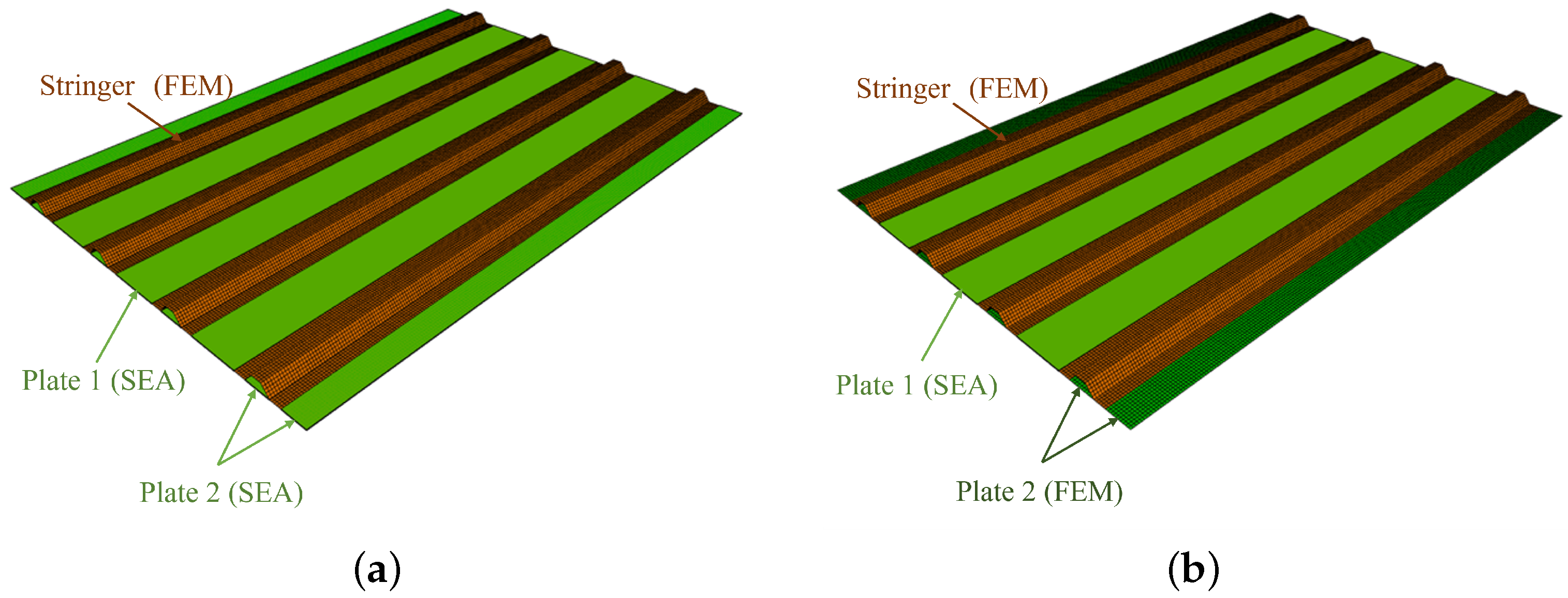
Section 4.2, now two Hybrid 2D FE-SEA models are realised. The first of them has all skin parts modelled as statistical subsystems while the stiffeners are represented as deterministic subsystems (Hybrid 2D (1)—
Figure 17a). In consideration of the small width of the skin parts located below the stiffeners and at the extremities, and in order to obtain a more accurate solution at lower frequencies, an additional Hybrid model was developed (Hybrid 2D (2)—
Figure 17b) having also such skin parts modelled as FEM subsystems.
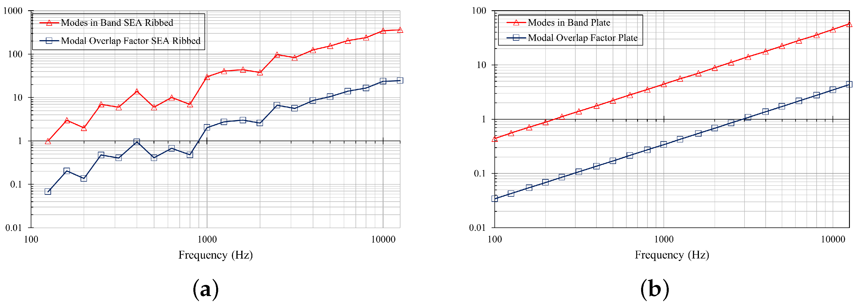
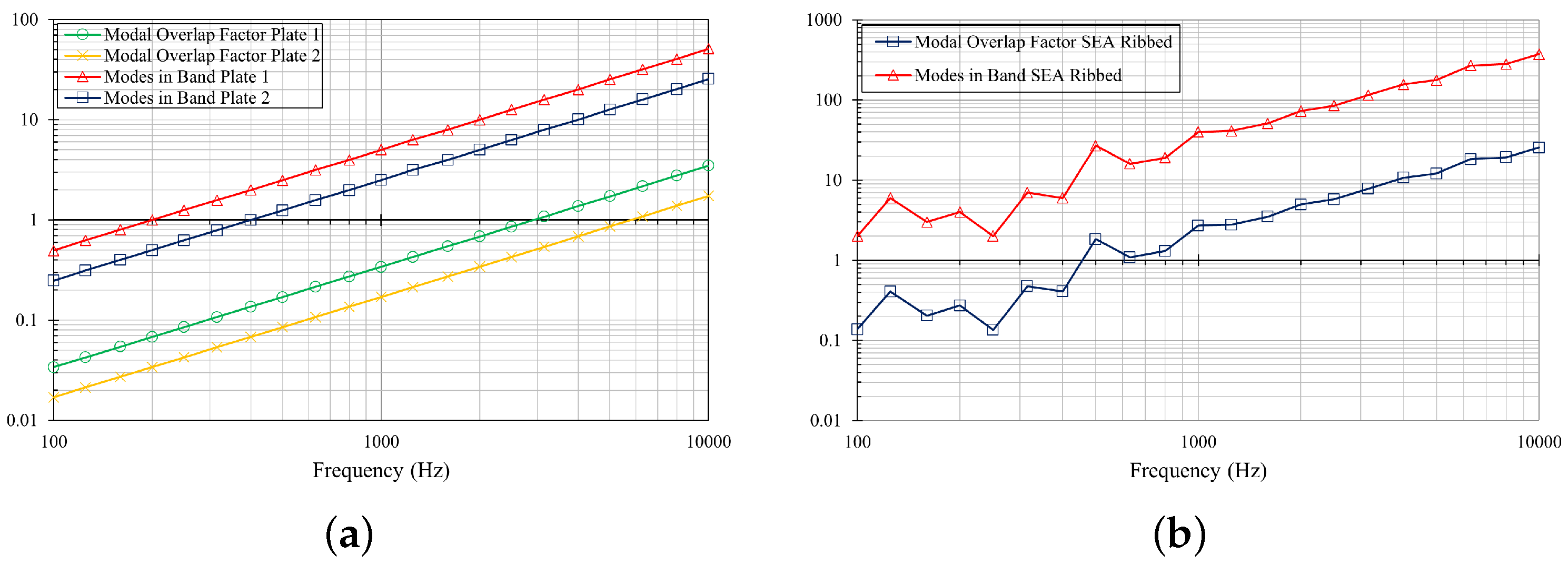
To better clarify the characteristics of the last Hybrid models, only those parts of the skin included between the stringers (identified as Plate 1 in
Figure 17a), having a MOF greater than one in the mid-frequency range (
Figure 18a), are modelled as SEA components, whereas the remaining skin parts (identified as Plate 2 in
Figure 17a) covered by the stringer or located at the panel extremities are modelled as FEM components (
Figure 17b).
The SEA Ribbed subsystem presents a monotonically increasing MOF that is greater than one from nearly 800 Hz (
Figure 18b).
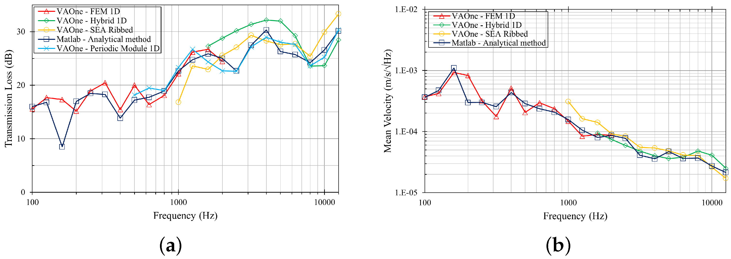
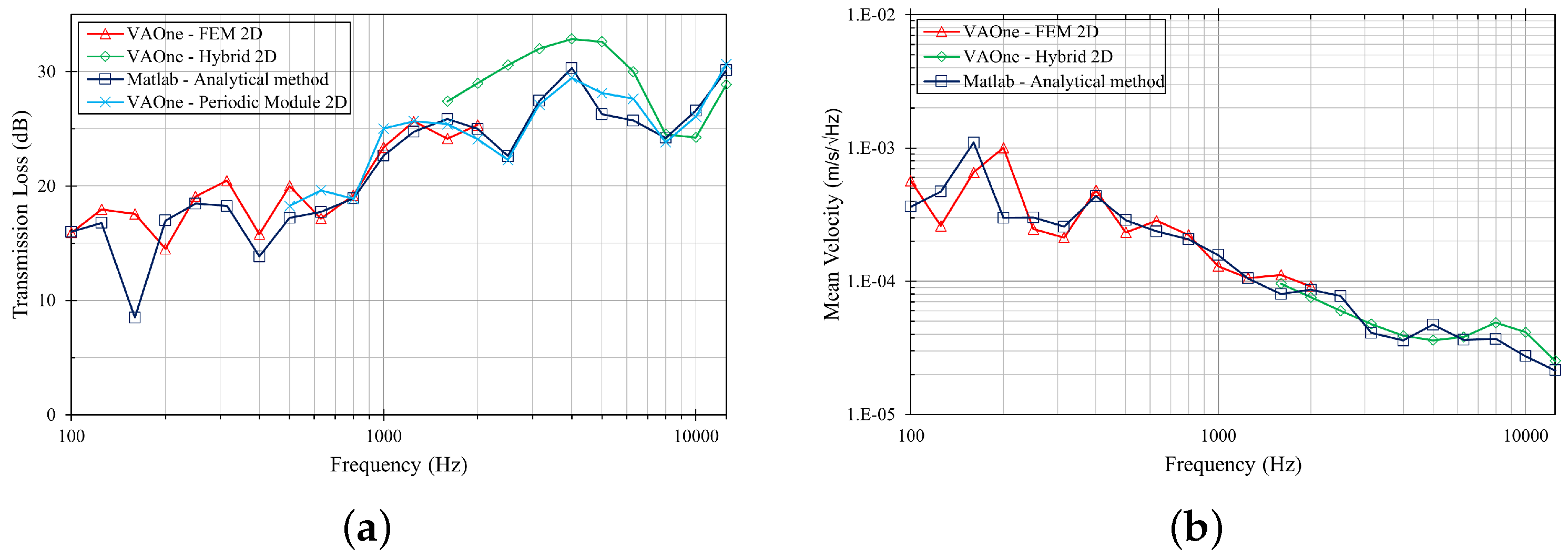
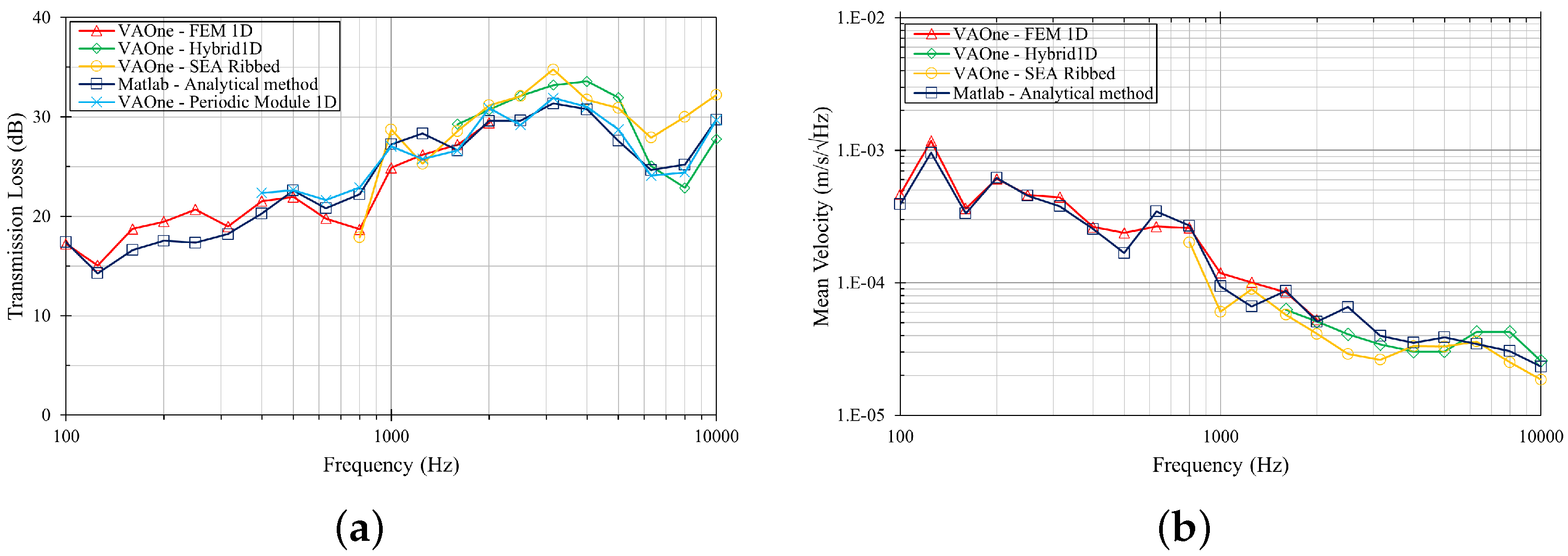
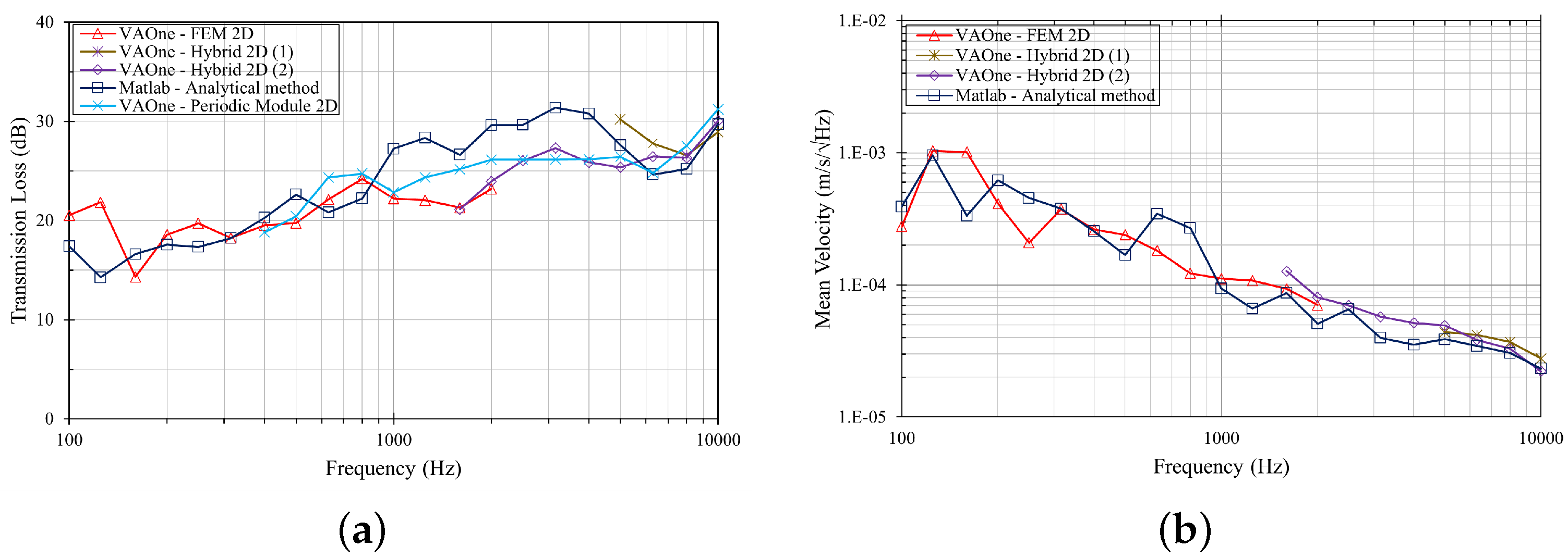
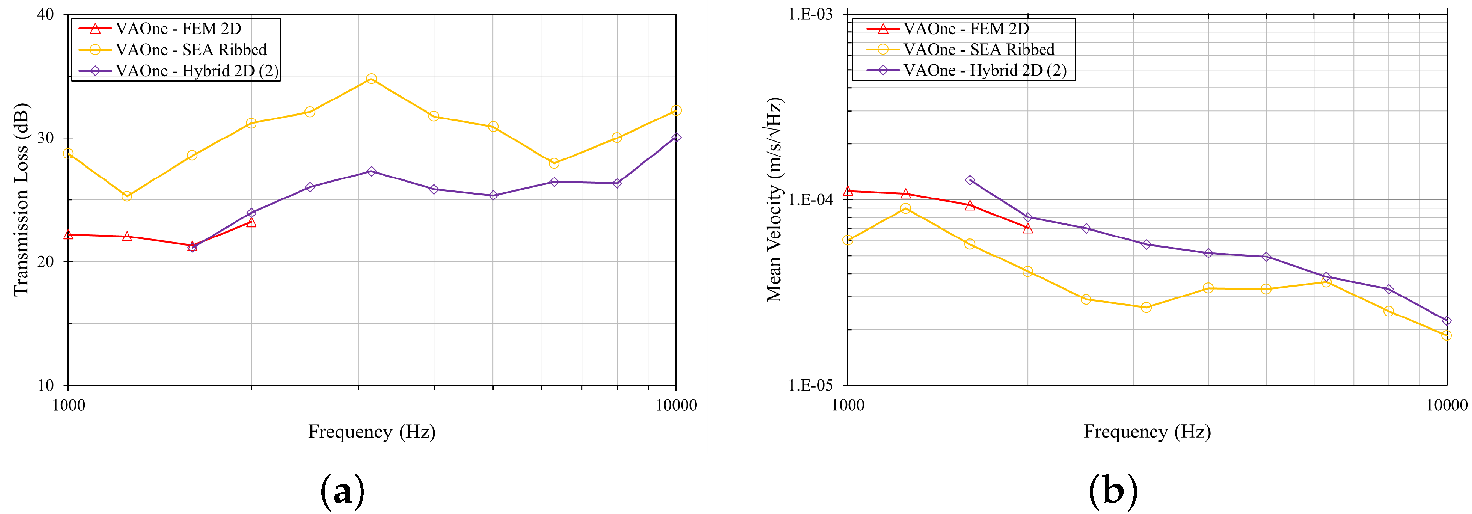
Comparison of the transmission loss and vibration levels predicted by the different models for a stiffened panel with unconventional hat-stringers are shown in
Figure 19 and
Figure 20.
The vibro-acoustic response of all the 1D stringers models (analytical, SEA ribbed and FEM) are consistent over the whole frequency range (nearly same results as shown in
Figure 19). The TL of the models with 2D stiffeners (FEM, Hybrid FE-SEA, periodic solution, all of them with stiffeners modelled with shell-type FEs), deviates from that provided by 1D stringers models starting from 900 Hz, as shown in
Figure 20 where only the analytical solution (blue curve) was reported as representative of all the 1D stringers models.
As already highlighted, SEA modelling with the Ribbed element is the only approach that can be used to estimate the vibro-acoustic responses of large and stiffened structures in the high frequency range.
At the same time, as confirmed from the results reported in
Figure 20, a conventional Ribbed element in which stiffeners are modelled according to 1D properties are not accurate in dealing with unconventional stiffeners. The scientific explanation behind such behaviour is associated with extreme simplification in considering the specific reinforcing element as one-dimensional, thus neglecting the significant dynamic contribution appearing at medium frequency range, deriving from being a two-dimensional structural components.
The need for a simplified procedure allowing us to preserve the potential of SEA Ribbed modelling while improving the accuracy for the examined unconventional panel has been fulfilled by taking advantage of specific features available in VAOne code, as described in the next section.
5. Equivalent Sea Ribbed Model
In the previous section, the impossibility of directly using SEA Ribbed to predict the vibro-acoustic behaviour of panels with unconventional stiffeners was observed (
Figure 21), whereas for conventional panels, the same approach provides an adequate trend estimate (
Figure 22).
In the following section, an attempt will be made to define an SEA Ribbed equivalent panel, having fictitious assigned properties (shear modulus), opportunely calibrated to replicate the dynamic behaviour of panels with unconventional stringers. As demonstrated in the previous section, the Hybrid model in which the entire stiffener area is represented as an FEM subsystem to retain the complex structural dynamic interaction mechanism, is assumed to be the most reliable reference to be employed to evaluate the TL and vibration level characterizing the reinforced panel response to a diffuse acoustic field in the medium-high frequency range.
5.1. Optimisation Process
The design of an equivalent structure with an optimised fictitious value of the shear modulus can be achieved by using optimisation tools, which are commercially available. For example, in Matlab, the fmincon can be used to solve the optimisation problem from the definition of some specific parameters: an objective function, initial conditions and constraints.
The objective function (Equation (
13)) can be defined as the root mean square error (RMSE), which measures the average of the squares of differences between the reference curves (
and
) and the actual curves (
and
v). These values are functions of frequency and can be represented by vectors of N components, where N is the number of third-octave frequency response values acquired in the overall examined frequency range.
The vibro-acoustic response (
TL and space-average mean vibration velocity) of the unconventional stiffened panels, obtained by FEM and Hybrid FE-SEA approaches (
Figure 21), can be considered as the benchmark (reference values).
In order to allow for both acoustic and vibrational response, the RMSE will be the sum of the of transmission loss and mean vibrational velocity RMSEs. Since there are different orders of magnitude between the TL and the velocity, it is essential to normalise the contributions with the corresponding mean reference value ( and ). The latter is simply obtained from the arithmetic mean of the reference vibro-acoustic response vector, i.e., by summing all the values of the vector’s components and dividing by the number of components. A W term is also introduced to weight the acoustic or vibrational contribution differently.
5.2. General Laminate Property Applied to Ribbed Sea Subsystems
The general laminate is a physical property used to assign specific physical parameters to SEA shell subsystems in VAOne code. Such property is used to model composite panels fabricated from a lay-up of isotropic elastic, orthotropic elastic and visco-elastic layers. In particular, a frequency-varying shear modulus can be assigned as the elastic property to the skin component of an SEA Ribbed subsystem.
The concept is to use the optimisation procedure to search for the shear modulus function that minimises the previously mentioned objective function (Equation (
13)).
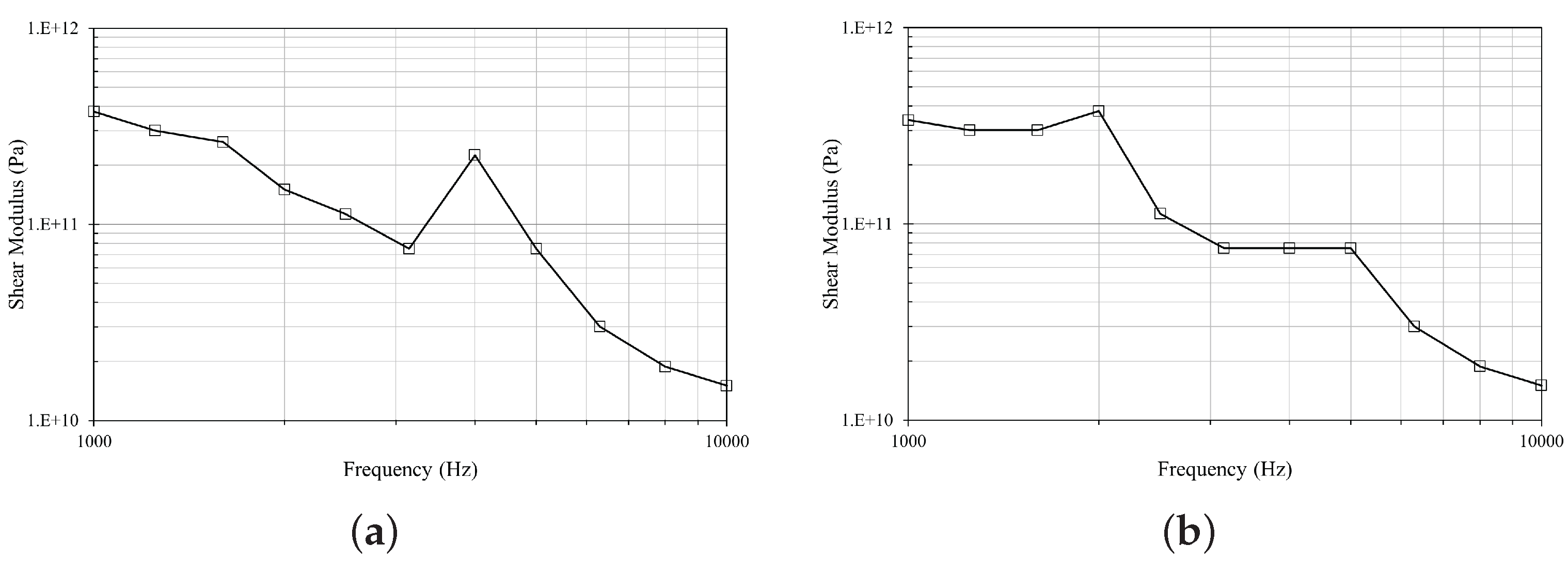
Two objective functions are considered: one with an RMSE that considers only the transmission loss contribution as reference (
) and another taking into account both the transmission loss and the velocity contribution (
). The corresponding equivalent shear modulus obtained are shown in
Figure 23.
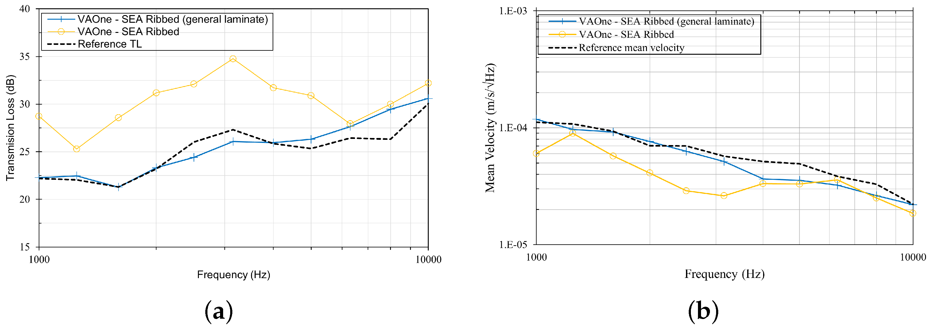
In
Figure 24 and
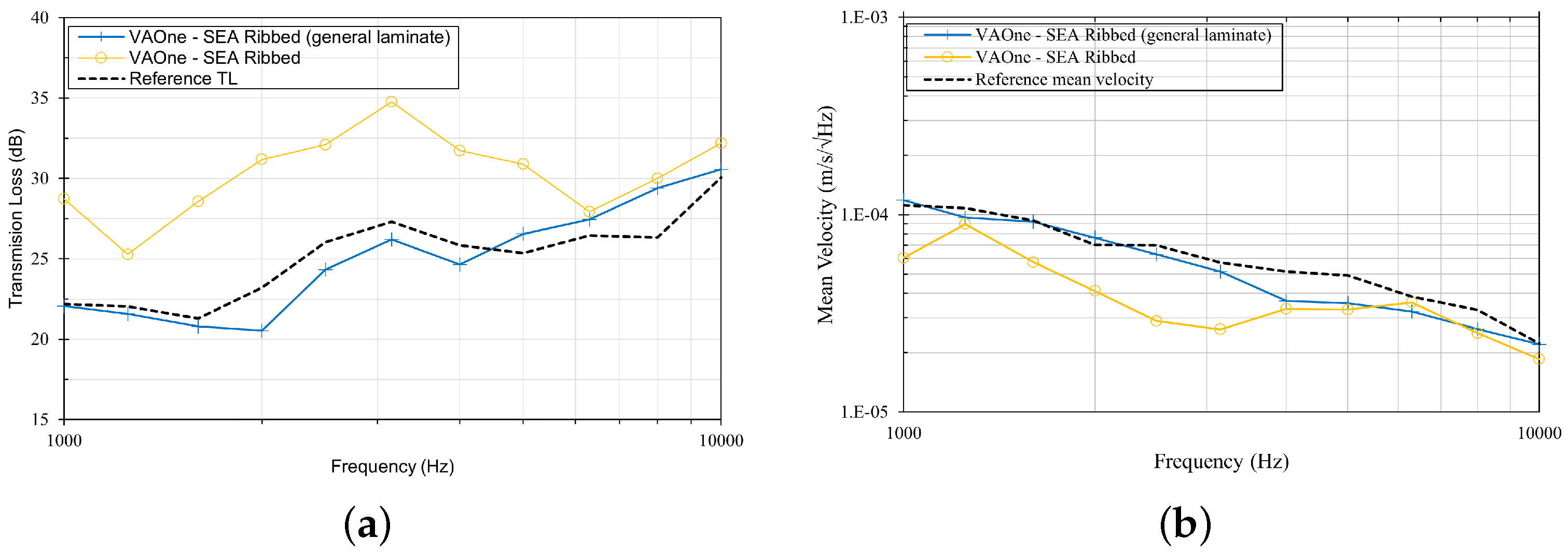
Figure 25, a comparison of the vibro-acoustic responses obtained by the SEA Ribbed panel modelled with a calibrated shear modulus and the reference values (FEM and Hybrid FE-SEA responses) can be observed.
A very good match of the vibro-acoustic responses up to 6000 Hz is obtained considering an objective function based on the only TL (
Figure 24). For higher frequencies, an increasing discrepancy is recorded but still with remarkable improvements with respect to the non-optimised SEA ribbed panel. If velocity is also considered in the objective function (
Figure 25), a slight worsening of the TL matching is observed with a correspondent slight improvement in terms of mean vibration velocity matching.
Panel assemblies with unconventional stiffeners are therefore suitable to be studied with pure SEA approaches downstream of the previously presented procedure. Experimental data or vibro-acoustic responses, of a single panel with unconventional stiffeners, obtained from more sophisticated modelling techniques can be used as a benchmark in an optimisation process to design an equivalent panel able to reproduce the exact dynamics when using an SEA Ribbed modelling approach. Such a technique can then be employed to deal with complex structures by assembling different SEA Ribbed subsystems, then preserving the advantages of SEA modelling.
6. Conclusions
This work was focused on the characterisation of the dynamic behaviour of aeronautical panels reinforced with unconventional stringers, as well as on the identification of numerical models able to accurately reproduce the dynamics of the examined structures. To this end, the most appropriate modelling procedures to be implemented were identified.
An analytical method able to predict the transmission loss and mean vibrational velocity of a stiffened panel having different boundary conditions, excited by a diffuse acoustic field, was implemented and extended to allow for the assessment of the panel mean vibration velocity response. This procedure was necessary to confirm the predictive capabilities and limits of different numerical techniques, with special attention devoted to the SEA Ribbed approach, which is considered the only feasible one in the medium/high frequency range to study complex systems constituted by large stiffened panels, such as in the case of a fuselage of a general aviation aircraft.
In the case of conventional stiffened panels, the accuracy of the results obtained by SEA Ribbed modelling was assessed, so that models with stiffeners represented by two-dimensional elements (shells) can be skipped with consequent savings in terms of run times and pre-processing effort, as long as the stiffener section can be assumed as stiff and compact enough in the investigated frequency range. Whereas, in the case of unconventional stiffened panels, it has been established that FEM is still essential in the low/medium frequency range, while Hybrid FE/SEA and/or WFEM are required in the medium/high frequency range. The Hybrid approach, although performing well, brings with it the limitations of FEM (computational effort that grows exponentially with the frequency of analysis) and this makes it inapplicable to structures composed of several stiffened panels (e.g., an aircraft fuselage). At the same time, it has been shown how the SEA Ribbed approach, purposely developed to implement simplified stiffened shells subsystems in an SEA model, provides inadequate responses for the examined structure, particularly at the frequencies of greatest interest, i.e., the medium/high frequencies.
In order to preserve the intrinsic simplicity of the SEA Ribbed modelling for vibro-acoustic analyses performed on complex structures, the possibility of defining an equivalent SEA Ribbed panel model characterised by a fictitious frequency dependent shear modulus, able to reproduce the correct vibro-acoustic dynamics of the structure, was examined, providing a very encouraging response.
Future activities will be devoted to validating the models and methodologies described through experimental data acquired for the typology of structure investigated in the present work, along with other analyses performed with commercial numerical tools to further assess the accuracy of the proposed models.


