Article

High-Performance Properties of an Aerospace Epoxy Resin Loaded with Carbon Nanofibers and Glycidyl Polyhedral Oligomeric Silsesquioxane

by
Liberata Guadagno
1,
Spiros Pantelakis
2,
Andreas Strohmayer
3 and
Marialuigia Raimondo
1,*
1
Department of Industrial Engineering, University of Salerno, Via Giovanni Paolo II, 132, 84084 Fisciano, Italy
2
Department of Mechanical Engineering and Aeronautics, University of Patras, Panepistimioupolis Rion, 26500 Patras, Greece
3
Department of Aircraft Design, Institute of Aircraft Design (IFB), University of Stuttgart, Pfaffenwaldring 31, 70569 Stuttgart, Germany
*
Author to whom correspondence should be addressed.
Aerospace 2022, 9(4), 222; https://doi.org/10.3390/aerospace9040222
Submission received: 22 February 2022 / Revised: 6 April 2022 / Accepted: 12 April 2022 / Published: 16 April 2022
(This article belongs to the Special Issue Advances in Aerospace Sciences and Technology III)

Abstract

:
This paper proposes a new multifunctional flame retardant carbon nanofiber/glycidyl polyhedral oligomeric silsesquioxane (GPOSS) epoxy formulation specially designed for lightweight composite materials capable of fulfilling the ever-changing demands of the future aerospace industry. The multifunctional resin was designed to satisfy structural and functional requirements. In particular, this paper explores the advantages deriving from the combined use of GPOSS and CNFs (short carbon nanofibers) to obtain multifunctional resins. The multifunctional material was prepared by incorporating in the epoxy matrix heat-treated carbon nanofibers (CNFs) at the percentage of 0.5 wt% and GPOSS compound at 5 wt% in order to increase the mechanical performance, electrical conductivity, thermal stability and flame resistance property of the resulting nanocomposite. Dynamic mechanical analysis (DMA) shows that the values of the Storage Modulus (S.M.) of the resin alone and the resin containing solubilized GPOSS nanocages are almost similar in a wide range of temperatures (from 30 °C to 165 °C). The presence of CNFs, in the percentage of 0.5 wt%, determines an enhancement in the S.M. of 700 MPa from −30 °C to 180 °C with respect to the resin matrix and the resin/GPOSS systems. Hence, a value higher than 2700 MPa is detected from 30 °C to 110 °C. Furthermore, the electrical conductivity of the sample containing both GPOSS and CNFs reaches the value of 1.35 × 10⁻¹ S/m, which is a very satisfying value to contrast the electrical insulating property of the epoxy systems. For the first time, TUNA tests have been performed on the formulation where the advantages of GPOSS and CNFs are combined. TUNA investigation highlights an electrically conductive network well distributed in the sample. The ignition time of the multifunctional nanocomposite is higher than that of the sample containing GPOSS alone of about 35%.

Graphical Abstract

1. Introduction

1.1. Overview of Smart and Multifunctional Materials in the Aerospace Industry

The aerospace industry is one of the key sectors that has driven the growth in the use of composite materials in recent years [1,2,3,4,5], thanks to large manufacturers attracted by the considerable potential for reducing fuel consumption and carbon dioxide emissions [6,7,8,9]. Commercial operators in the sector increasingly tend to emphasize the importance of some factors such as energy-saving, environmental compatibility, reliability, safety and comfort of transport [10]. This involves developments in research and applications oriented towards the study of newly conceived structural architectures, the dissemination of more accurate analysis methodologies, the rationalization of inspection methods and procedures, and the optimization of production processes, as well as towards use of new materials. On the basis of these themes, the lines of research involving composite materials and, more specifically, smart materials, are strategic [11]. In many cases, such smart materials are also referred to as multifunctional materials because they are required to perform multiple functions (self-healing and remodeling materials, materials for sustainability and energy, advanced manufacturing of multifunctional materials, sensor, actuation, and control) [12,13]. Materials for aerospace applications face many challenges. Specifically, these materials are able to recognize and evaluate the extent of an external stimulus, and to react reversibly with an appropriate response by changing both physical and mechanical properties. They are therefore capable of combining mechanical and functional properties in a single system.

1.2. Technological Impact of the Multifunctional Systems

The ability of multifunctional systems to respond to their environment in a useful manner has a broad technological impact. In fact, they can allow:
(a)
Overcoming the criticalities that arise during the operational life of the aircraft linked to the deterioration of the structure with worsening of the general mechanical properties,
(b)
Minimizing the effects due to unusual load conditions,
(c)
Reducing the effects of fatigue, compensate for harsh local conditions,
(d)
Reducing vibration levels,
(e)
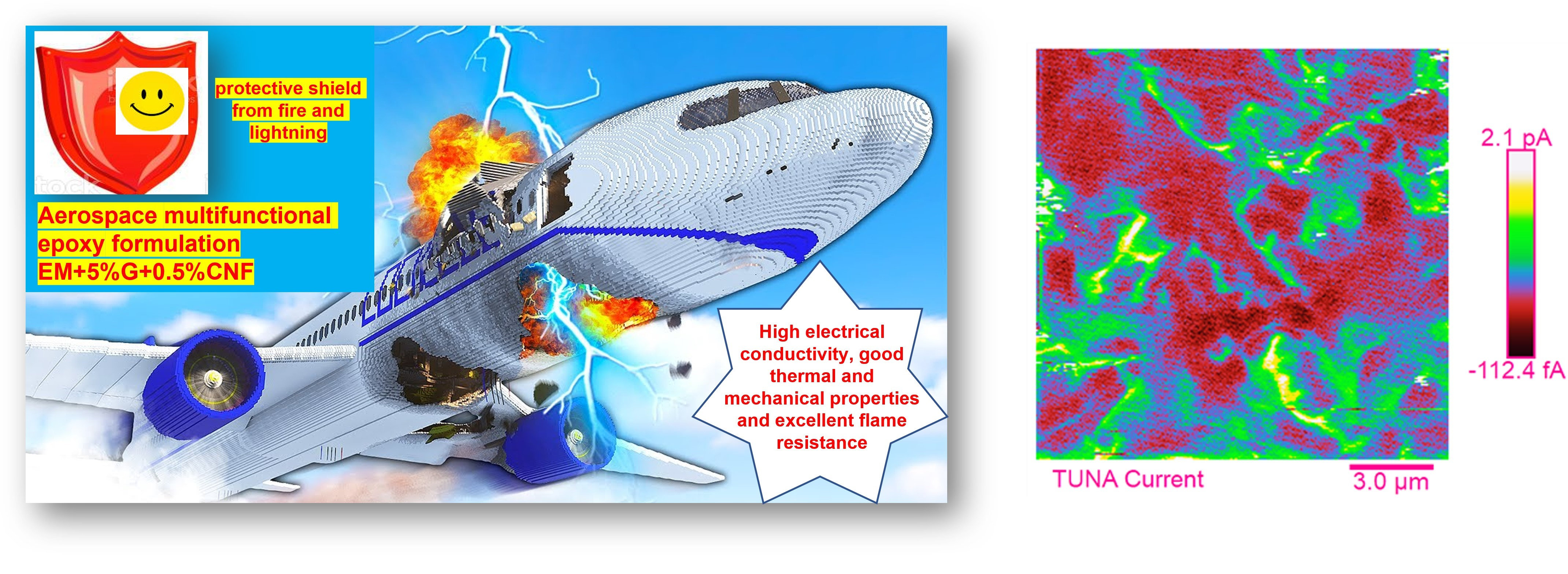
effective shielding from electromagnetic interference with protection against lightning damage,
(f)
Ensuring good resistance in the event of high temperatures and fire.
The ever-increasing demand in the aeronautical/aerospace structural design of materials with high mechanical performance has determined, in recent decades, the diffusion of polymer matrix composites (PMCs) mainly reinforced with carbon fibers (Carbon Fiber-Reinforced Polymers, CFRP). The main limitations in the use of PMCs are the high sensitivity to environmental agents and low operating temperatures. Furthermore, these materials do not withstand exposure to fire, and this is due to the possible ignition of the epoxy matrix. In this context, it becomes essential to develop a composite that combines the structural performance of CFRPs with good resistance to high temperatures and fire [14], as well as effective lightning protection [15] while preserving thermal stability and good mechanical properties.

1.3. Objectives and Novelty of the Research Work

This work presents a new hybrid epoxy composite that effectively meets the requirement of multifunctionality through an intelligent combination of a structural function with two additional functional capabilities, namely electrical and flame-retardant properties. To impart electrical conductivity to the final nanocomposite, carbon nanofibers heat-treated at 2500 °C [16,17], suitably designed to carry lightning currents, were well-dispersed within the host tetrafunctional epoxy matrix. It is worth noting that the use of conductive material is required as the dissipation of electrostatic charges is essential in applications for the aerospace industry where highly sensitive electronic components are present. In fact, there are many problems facing aircraft in the air during flight, such as lightning strikes [18], which knock the aircraft’s surfaces such as the fuselage, where a high current is generated, which, if not dissipated, will enter the airplane and causes dangerous fires. In this regard, our work proposes a new multifunctional formulation where POSS-based nanocages are used for flame protection of carbon fiber-reinforced aeronautic composites. In particular, for the formulated nanofilled resin, direct current (DC) conductivity value is 1.35 × 10⁻¹ S m−1, limiting oxygen index (LOI) (% O2) value is 29 and the peak of heat release rate (PHRR) is 506 kW m−2. In light of the results obtained, the developed smart formulation represents a valid and winning alternative solution to overcome some problems facing aircraft in the air, such as lightning, thus avoiding the accumulation of electrostatic charges and ignition of flames on the surfaces of the aircraft, thereby improving the safety of passengers without impacting the aircraft weight with heavy metal nets. The GPOSS, solubilized at the molecular level in the matrix, performs a dual function of flame retardant and viscosity modulator [19,20], thus favoring the optimal dispersion of the carbon nanofibers and, at the same time, ensuring good mechanical performance. Polyhedral oligomeric silsesquioxanes (POSS) are a class of nanostructured silica-based compounds that can be considered as organic and inorganic hybrid materials. POSS are characterized by Si-O-Si bonds that form the nanometer-sized cage-like structures with Si atoms at the top [21] with the organic pendent groups suitably designed to reach the wished affinity with the host polymeric matrix [22]. Recent papers have also analyzed POSS interaction (Si-O-Si) with epoxy [23,24,25]. POSS find wide application as nanofillers for polymeric composites due to their environmental neutrality, good heat resistance and excellent thermo-oxidative stability [26,27,28]. They are characterized by the ability to produce a ceramic phase at high temperatures (silica and/or silicon oxycarbide), which favors the formation of a barrier capable of hindering the diffusion of oxygen during combustion, thus increasing the flame resistance of the material. The use of POSS has also received great attention due to its ability to improve mechanical and thermal properties of composite materials [29]. In summary, the innovative aspect of this research concerns the development of a new multifunctional formulation obtained with a targeted selection of molecules capable of imparting functional properties to the resin while preserving outstanding mechanical performance. Moreover, TUNA was used for nanometric-scale electrical characterization.

2. Materials and Methods

In this work, carbon nanofibers (CNFs) belonging to the Pyrograf III family were used as conductive nanofillers. They were manufactured by Applied Sciences, Inc., Cedarville, OH, USA using Vapor-grown Carbon Fiber (VGCF) Manufacturing Technology. CNFs are available in a free-flowing powder form (typically 99% mass is in a fibrous form). They have been heat-treated at 2500 °C to ensure a winning combination of electrical and mechanical properties [16,17,30,31,32]. The heat treatment makes the CNF walls straight and smooth, as is evident from the morphological survey shown in the Section 3. Carbon nanofibers are characterized by the following structural parameters: lengths ranging from 50 to 100 µm, nanofiber wall density between 2.0 and 2.1 g cm−3, density values between 1.4 and 1.6 g cm−3, specific surface area of 54 m2 g−1, average pore volume of 0.120 cm3 g−1, and average pore diameter of 89.30 angstroms. The unfilled epoxy matrix, defined hereinafter with the acronym EM, is composed of the tetraglycidyl methylene dianiline (TGMDA) tetrafunctional resin (80 wt%), 1,4-Butanediol diglycidyl ether (BDE) reactive diluent (20 wt%), and diaminodiphenyl sulfone (DDS) curing agent in a stoichiometric quantity solubilized at 120 °C for 20 min. All these chemicals were supplied by Sigma-Aldrich. The steps of the preparation procedure that lead to obtaining the multifunctional epoxy mixture containing GPOSS and CNFs are described below. GPOSS, purchased from Hybrid Plastics Company (Hattiesburg, MS, USA), has the following characteristics: (a) molecular/chemical formula: (C6H11O2)n(SiO1.5)n n = 8, 10, 12; (b) molecular weight: 1337.88 (for n = 8). Figure 1 shows the chemical structure of GPOSS.
GPOSS (5 wt%), here named G, in the form of viscous liquid was solubilized (at molecular level) in the epoxy blend formed by TGMDA and BDE using two steps consisting of ultrasonication (Hielscher model UP200S (200 W, 24 kHz)) and subsequent magnetic stirring for 1 h in heated oil bath at 120 °C. The stirring step causes the complete dissolution of the filamentous residues of the GPOSS until the mixture becomes clear. Finally, the multifunctional nanocomposite EM + 5%G + 0.5%CNF was obtained by incorporating CNF nanofiller at 0.5 wt% into the liquid mixture containing TGMDA, BDE and G compounds through an ultrasonication for 20 min and then by solubilizing a stoichiometric amount of DDS at 120 °C for 20 min. It is worth noting that 0.5 wt% corresponds to the weight percentage of nanofillers CNFs above the Electrical Percolation Threshold (EPT) [16]. Similarly, the sample EM + 5%G was obtained by solubilizing a stoichiometric quantity of DDS at 120 °C for 20 min in the liquid mixture consisting of TGMDA, BDE, and G compounds. Furthermore, the sample EM + 0.5%CNF was obtained by dispersing CNF at 0.5 wt% within the liquid mixture containing TGMDA and BDE through an ultrasonication for 20 min and then by solubilizing a stoichiometric amount of DDS at 120 °C for 20 min. All formulated samples were solidified in an oven at 125 °C for 1 h and then at 200 °C for 3 h.
The flame resistance of GPOSS-based epoxy samples was evaluated by limiting oxygen index (LOI) measurement and mass loss calorimetry. The LOI tests were carried out by igniting barrels of 80 × 10 × 3 mm3 suitably fixed in a vertical position with a burner. ASTM 2863 was used to measure the LOI, which represents the minimum concentration of oxygen in a nitrogen/oxygen mixture necessary to simply sustain the sample combustion. For mass loss calorimeter tests, plates of 100 × 100 × 3 mm3 were exposed to a radiant cone (50 kW m−2) by means of a forced ignition. The measurement of the heat of combustion released was carried out using a thermopile as required by the standard ISO 13927.
A Mettler DSC 822 differential scanning calorimeter (Mettler-Toledo, Novate Milanese, Italy) in a flowing nitrogen atmosphere was utilized to provide calorimetric data for calculating the curing degree (CD) of the samples. Thermogravimetric analysis (TGA) (Mettler TGA/SDTA 851 thermobalance) was accomplished by heating the samples from 0 °C to 900 °C at a 10 °C/min heating rate under both nitrogen and air flows.
Solid samples with dimensions 2 × 10 × 35 mm3 were subjected to dynamic mechanical analysis (Tritec 2000 DMA -Triton Technology, Leicester, UK) in the temperature range between 30 °C and 320 °C at the scanning rate of 3 °C/min, with displacement amplitude of 0.03 mm and frequency of 1 Hz.
Pictures of the CNF, EM + 0.5%CNF, and EM + 5%G + 0.5%CNF were acquired using a Scanning Electron Microscope—SEM (mod. LEO 1525, Carl Zeiss SMT AG, Oberkochen, Germany). Thin slices were obtained by cutting the solid samples EM + 0.5%CNF and EM + 5%G + 0.5%CNF with a microtome. These slices, before being morphologically analyzed, underwent an oxidizing treatment with an etching solution [16,19] in order to remove the amorphous part constituted by the resin, thus allowing us to discover the carbon nanofibers and evaluate the state of dispersion of them within the epoxy matrix.
The conductivity map of the nanodomains of the etched multifunctional composite EM + 5%G + 0.5%CNF was carried out by TUNA-AFM operating in contact mode with a cantilever holder and the sample containing conductive CNFs, electrically connected to an external voltage source. Platinum-coated probes with nominal spring constants of 35 N m−1 and an electrically conductive tip of 20 nm were used to perform the TUNA-AFM measurements, adopting the following control parameters: DC sample bias from 1 V to 2 V, current sensitivity of 1 nA/V, current range of 200 nA, number of pixels in X and Y (samples/lines) equal to 256, and scan rate in the range 0.9–1.5 Hz s−1. To ensure the reproducibility of the measurements, various areas of the sample were analyzed. The pictures were examined by Bruker software Nanoscope Analysis 1.80 (Build R1.126200).
The infrared spectra were obtained in absorbance by using a Bruker Vertex 70 FTIR-spectrophotometer (Billerica, MA, USA) with a resolution of 2 cm−1 (32 scans collected) in the range of 400–4000 cm−1, and the samples were spread on the KBr slice.

3. Results and Discussion

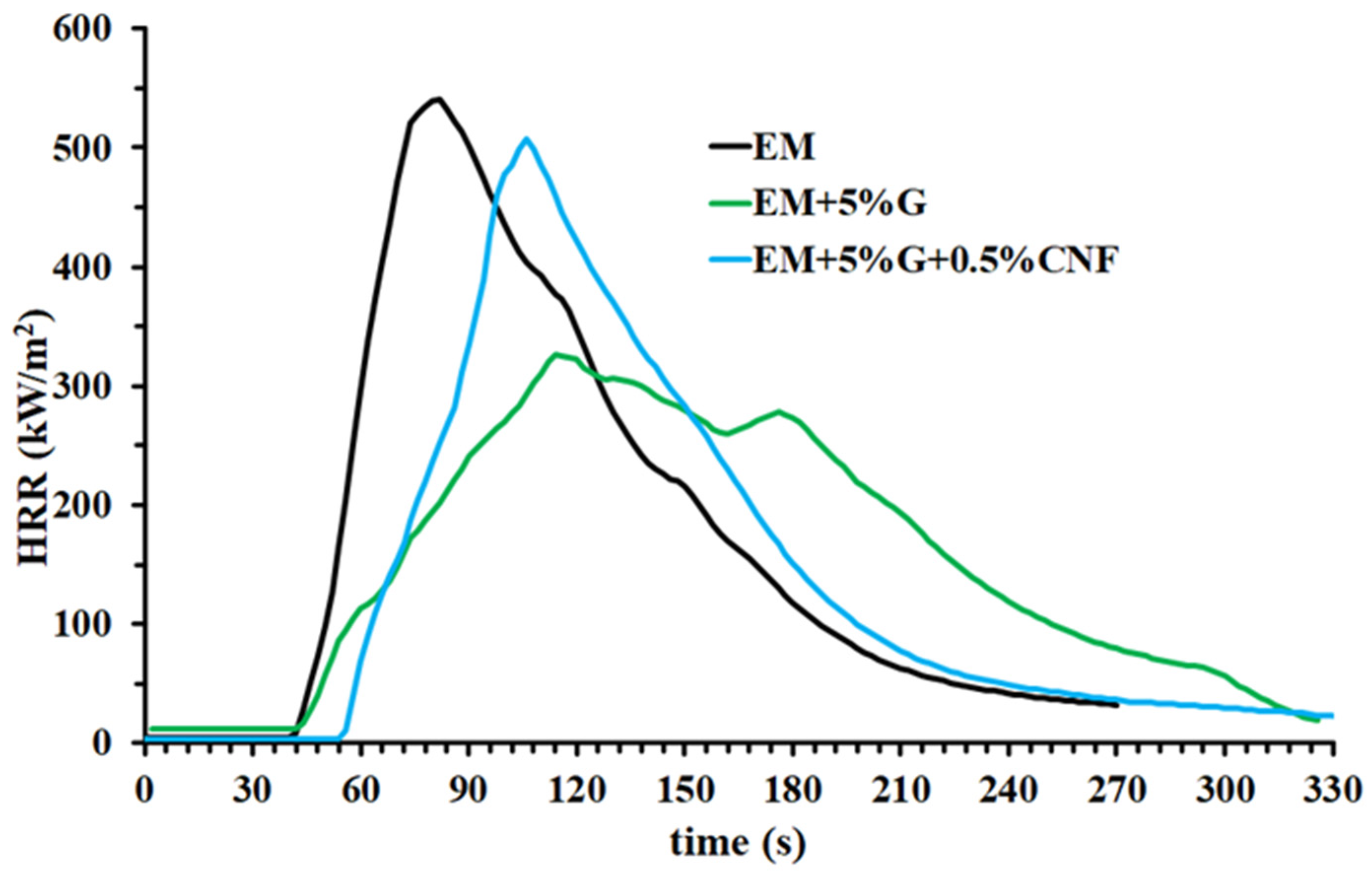
3.1. Fire Behavior of the Investigated Formulations

The fire behavior of the multifunctional nanocomposite EM + 5%G + 0.5%CNF containing the flame-retardant GPOSS (G) and the conductive carbon nanofibers (CNF) was investigated through the measurement of the limiting oxygen index, or LOI, which is the most commonly used method for evaluating the burning capability (in fact, the higher the LOI value, the higher the non-flammability) and mass loss calorimetry. The mass loss calorimeter allows determining the effective heat of combustion, which is constant for a given material when burnt at a fixed heat flux under constant ventilation conditions, assuming that the combustion of the material does not lead to complete oxidation. The peak of heat release rate (PHRR) stands for the utmost quantity of heat emitted by the material in the course of the combustion process and often it happens quickly, later than combustion. PHRR is one of the most significant burning parameters for estimating the fire safety of the material [33]. For this parameter, a lower value denotes a better flame retardant performance [34]. A meaningful indicator for estimating the flammability resistance of the polymer materials is the time-to-ignition, which is defined as the minimum exposure time needed for the sample to ignite and maintain flaming combustion [35]. This parameter therefore provides indications on how easily a material exposed to a given heat flow and in an oxygen-controlled environment can ignite and on the rate at which flaming combustion occurs. It contemplates various phenomena, such as the time it takes for the sample surface to reach pyrolysis temperature, as well as the material’s ability to produce a critical concentration of volatile flammable gases during the thermal decomposition process. Table 1 brings together the fire reaction properties of the analyzed epoxy samples for an incident heat flux of 50 kW/m2, namely the limiting oxygen index (LOI), the peak of heat release rate (PHRR) and the Time-to-Ignition (tig) values; errors based on the maximum deviation from the individual mean values are also reported.
In particular, Figure 2 exhibits the heat release rate (HRR) curve with time of the sample EM + 5%G + 0.5%CNF by comparing it with both curves of the unfilled resin EM and of the resin filled with the flame-retardant molecule GPOSS (G), namely the EM + 5%G sample. There is no doubt that the flame-retardant behavior found for the multifunctional composite EM + 5%G + 0.5%CNF, for which the LOI value of 29 is recorded, is due to the presence of GPOSS. In fact, GPOSS has a structure fully epoxidized with glycidyl groups, which make it compatible with epoxy resin and reactive diluent. The addition of 5 wt% of GPOSS strongly affects the flammability of the resin, leading to a notable increase in LOI from 27% of the neat epoxy resin EM to 33% for the sample EM + 5%G containing GPOSS [19,20]. For the multifunctional sample EM + 5%G + 0.5%CNF, we can observe the decrease in PHRR value (~7%) and the increase in LOI value (~8%) with respect to the unfilled resin EM. Moreover, it must be said that a really noteworthy result is represented by the significant increase of 35% in the time-to-ignition discovered for the sample EM + 5%G + 0.5%CNF (54 s) with respect to the unfilled resin EM (40 s) and even 29% compared to the sample EM + 5%G (42 s) containing GPOSS. Thus, the multifunctional nanocomposite EM + 5%G + 0.5%CNF shows the highest value of the time-to-ignition compared to that found for all other formulations analyzed in this work, playing a crucial role in perspective for all those applications in the aeronautical sector that require advanced materials that act as flame retardants, as well as having synergistic structural and functional capabilities also imparted by the use of conductive nanofillers.

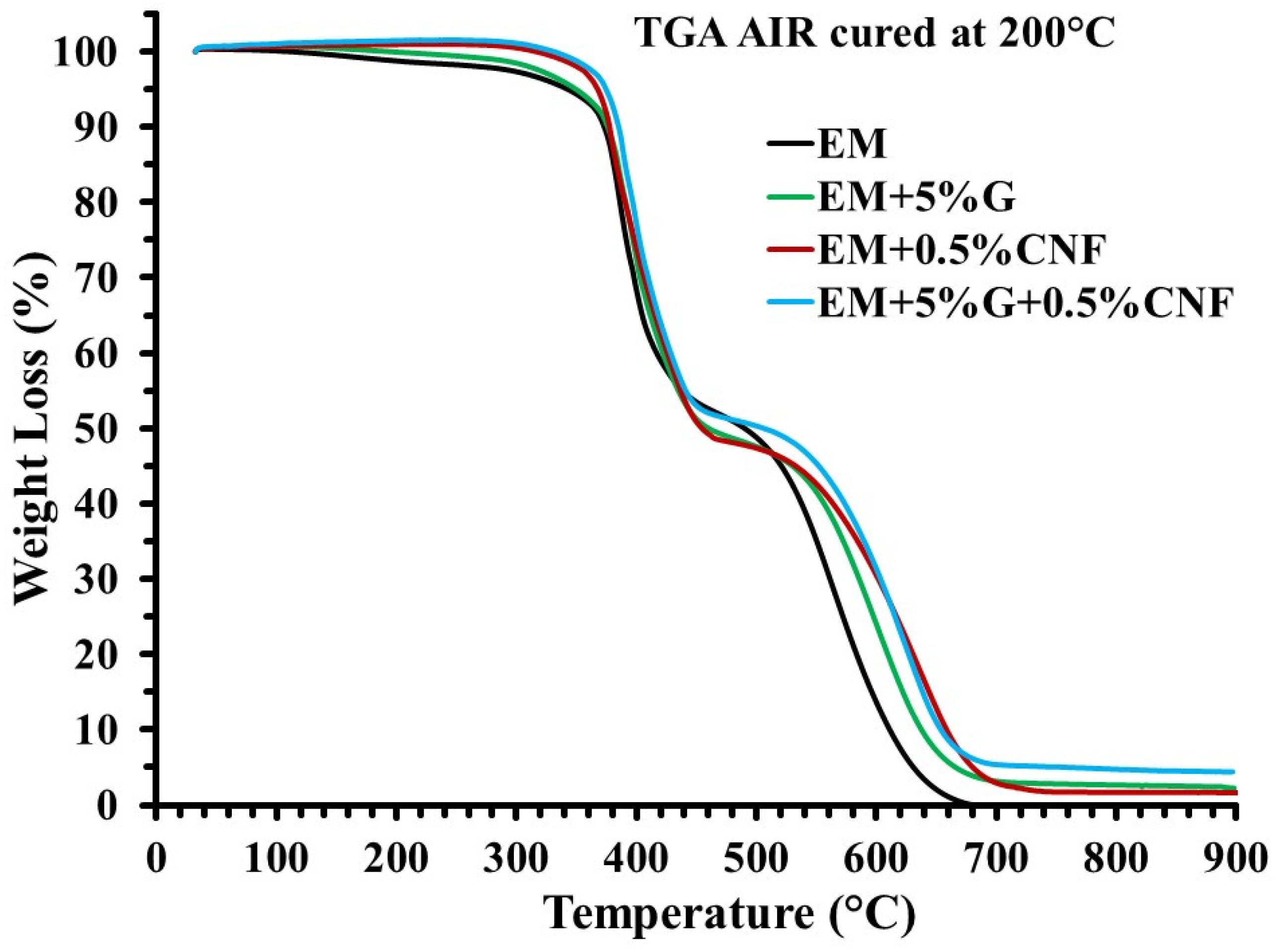
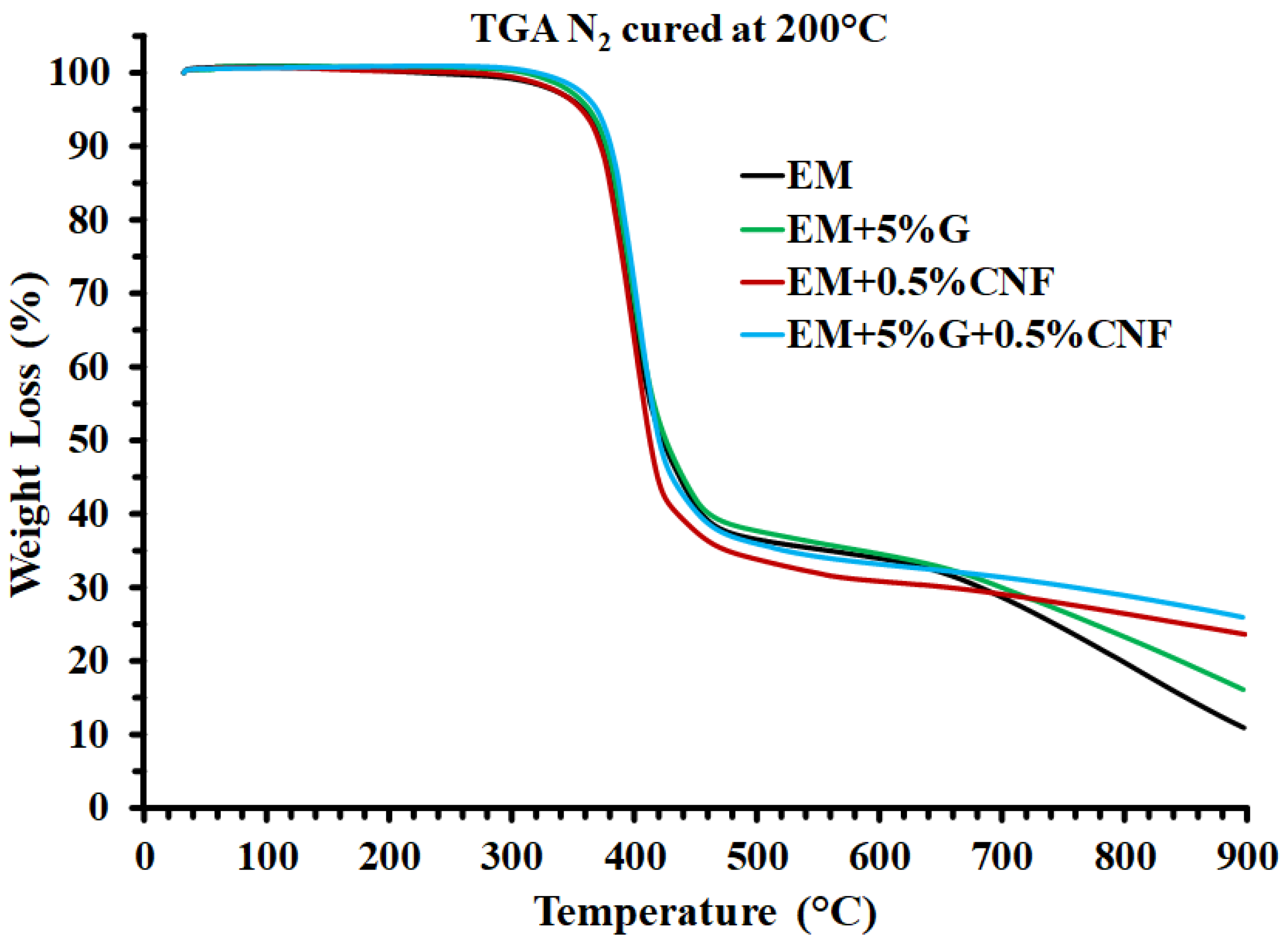
3.2. Thermal Behavior of the Investigated Formulations

Table 2 shows the curing degree (CD) values of different epoxy formulations, that is EM, EM + 5%G, EM + 0.5%CNF, EM + 5%G + 0.5%CNF. These values were assessed by differential scanning calorimetry (DSC) analysis [17] in an isothermal regime, as it represents the condition that characterizes the realization of various industrial processes. The planned curing cycle was performed in the oven by heating the samples at 125 °C for 1 h and then at 200 °C for 3 h. From Table 2, it is easy to see that the CD value is high for all the samples analyzed, reaching 100% for the sample loaded with 0.5% of carbon nanofibers (EM + 0.5%CNF). This result demonstrates that the conductive nanofiller plays a decisive role in increasing the efficiency of the curing process. The multifunctional composite EM + 5%G + 0.5%CNF shows a CD value of 90%, which, although it is lower than that of EM + 0.5%CNF due to the presence of the flame-retardant GPOSS, fully satisfies the stringent industrial requirements for the application of structural and functional resins in the aeronautical field.
The thermal behavior of the formulated epoxy samples was investigated by using thermogravimetric analysis (TGA). Figure 3 and Figure 4 show the TGA curves in air and in inert (N2) atmosphere of the samples EM, EM + 5%G, EM + 0.5%CNF, and EM + 0.5%CNF + 5%G, respectively.
Table 3 shows the values of thermal degradation temperatures corresponding to a weight loss of 5 wt% and 10 wt% (Td5% and Td10%, respectively), and the values of residue at 900 °C, for the measurements performed both in air and in nitrogen. In air, within the experimental temperature range, a two-step thermal degradation process can be observed for the analyzed samples, implying that the incorporation of GPOSS (G) and carbon nanofibers (CNF) in the matrix does not greatly alter the degradation mechanism of the formulation. As awaited, no residual yield was obtained at 900 °C for the unfilled resin EM (see Table 3). The residual yield, in air, for the resin containing GPOSS (G) and carbon nanofibers (CNF) is about 4 wt%, a value very near to the theoretical values of the residual silica contents in the resin [20].
From TGA in air (Figure 3), it can be seen that the nanofilled formulations are more thermostable than the EM unfilled epoxy matrix and the thermostability increases progressively for both the weight loss steps in passing from sample EM + 5%G to multifunctional nanocomposite EM + 0.5%CNF + 5%G, which exhibits the greatest stability to oxidative thermal degradation (see Table 3). In particular, TGA curves in the air highlight that, compared with the unfilled sample EM, the multifunctional epoxy resin EM + 0.5%CNF + 5%G shows a substantial increase in the thermal stability related to both the first and second stage of the degradation process. This increase, on the other hand, appears less pronounced in nitrogen (see Figure 4), especially in the first stage. Moreover, we can observe two distinctive and well-separated turns also for TGA curves in nitrogen.
The TGA curves in air show that CNFs play a decisive role in the stabilization of the formulation during the degradation phase. A similar effect, although much smaller, is also obtained from the dispersion of the GPOSS (G) flame retardant in the matrix (green curve). The synergistic action of GPOSS and CNFs most likely justifies the greater thermal stability detected for the multifunctional EM + 0.5%CNF + 5%G compared to all the formulations analyzed. In fact, the greater network density facilitates the formation of a structure that is more dimensionally stable and, therefore, impedes the degradation of the nanocomposite at elevated temperatures. It is worth noting that, the different trends of the TGA curves in air and nitrogen are indicative of the fact that the beginning of both the first and the second phase depends very much on the availability of oxygen.

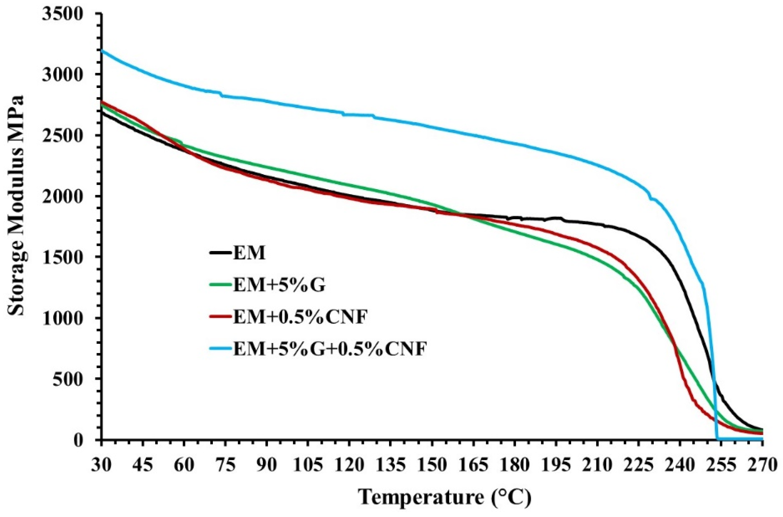
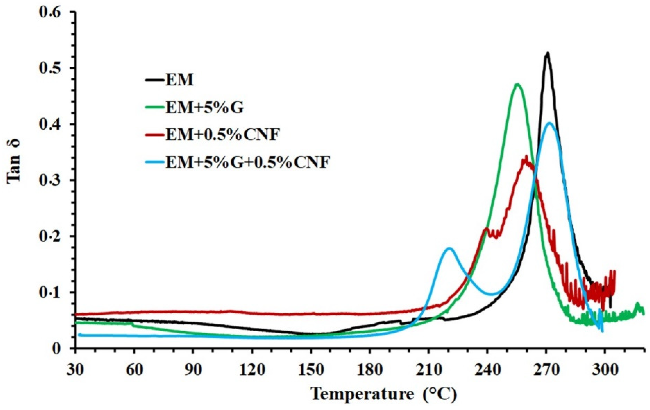
3.3. Dynamic Mechanical Behavior of the Investigated Formulations

Figure 5 presents the storage modulus of the investigated epoxy formulations.
From Figure 5, for the multifunctional nanocomposite EM + 0.5%CNF + 5%G, we can clearly observe an increase in the storage modulus across the wide temperature range between 30 °C and 255 °C compared to the other analyzed samples while maintaining the same trend. It is well-known that the POSS molecule is characterized by an inorganic rigid cage type structure (RSiO1.5) containing silicon and oxygen and organic groups attached to the silicon atoms [36]. The slight reinforcement effect manifested by GPOSS, in the range of temperature between 60 °C and 150 °C, with respect to the resin alone, can be explained in consideration of the fact that when the GPOSS is solubilized at the molecular level inside the epoxy matrix, the rigid silica cage determines the hardening of the resin also by virtue of the fact that the number of polyadditions increases due to the organic functionality identified by the glycidyl groups present on the GPOSS molecule. The strong increase in the storage modulus values determined by the combination of CNFs and GPOSS is most likely due to additional attractive interactions, based on hydrogen bonds, between -OH groups present on the wall of CNFs [31] and the oxygen atoms on the organic groups attached to the silicon atoms around the rigid nanocage of the POSS. Figure 6 presents the loss factor (tan δ) of the investigated epoxy formulations.
The DMA analysis shows the temperature of the damping peak identified as the glass transition temperature (Tg) for the different formulations tested (see Figure 6). From the graph in Figure 6, it can easily be seen that all epoxy samples have high Tg values between 255 °C and 270 °C, which are fully within a broad range for structural applications. In particular, in Figure 6, we can see that the sample EM + 5%G, containing only GPOSS, is characterized by the presence of a single tan δ peak centered at about 255 °C, which is associated with the glass transition temperature. Instead, for the multifunctional sample EM + 5%G + 0.5%CNF, containing both GPOSS and CNF, together with the main tan δ peak associated with the glass transition temperature, which manifests the max of the Tg at the same value (around 270 °C) shown by the unfilled epoxy matrix (EM), it is possible to observe another peak at a lower temperature. This second peak at around 220 °C is attributable to the presence of an additional phase with a different crosslinking density, which is placed at the interphase with nanofiller and resin. The presence of the carbon nanofiller strongly influences the structure of the epoxy matrix. In fact, during the curing, the crosslinking reaction is interrupted by the conductive network formed by the carbon nanofibers with the consequent formation of a phase with a reduced curing degree characterized by a lower glass transition. This behavior has been already observed for resin filled with other nanostructured forms of carbon, where together with the main glass transition temperature, a second peak in the tan δ at a lower temperature is observed. It has been highlighted that this second peak is due to a phase characterized by greater mobility of chain segments, most probably those near the walls of carbon nanofillers [37]. From Figure 6, for the sample EM + 5%G + 0.5%CNF, we can observe, in the light blue color, graph relaxation mechanisms at lower temperatures linked with a phase fraction with greater mobility (transition at lower temperatures) demonstrative of domains with a lower crosslinking density. In the resin, the coexistence of the two phases with different crosslinking densities is justified by the fact that the intensity of the main peak is reduced in favor of the one at a lower temperature. The explanation for this result seems to also be supported by thermal data. In fact, the multifunctional sample containing carbon nanofibers and GPOSS solidified in a static temperature regime is characterized by a curing degree (CD) lower than 100%.

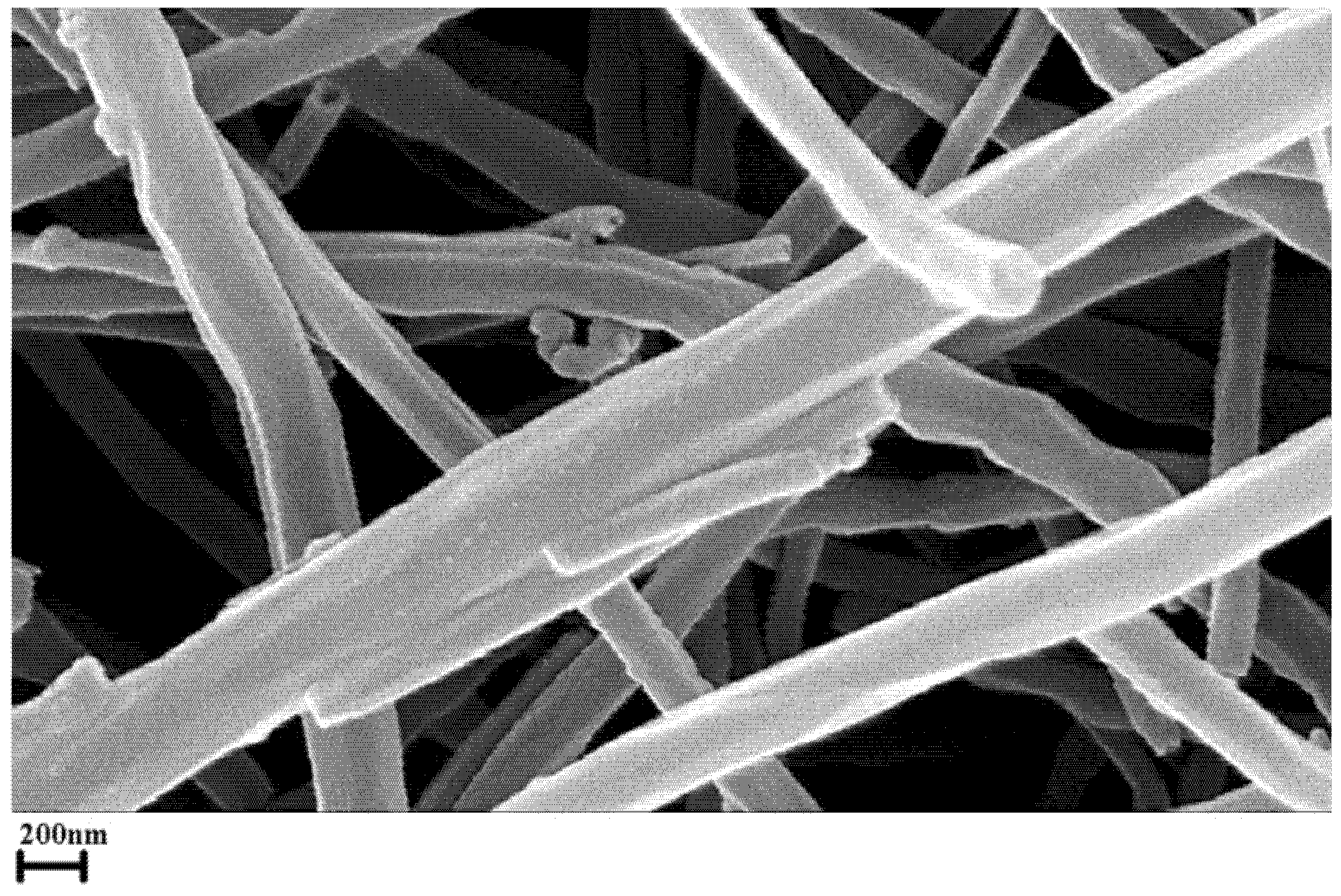
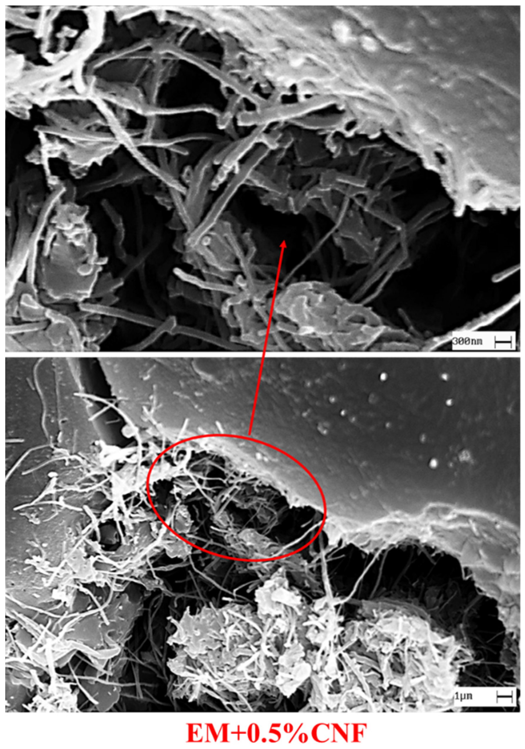
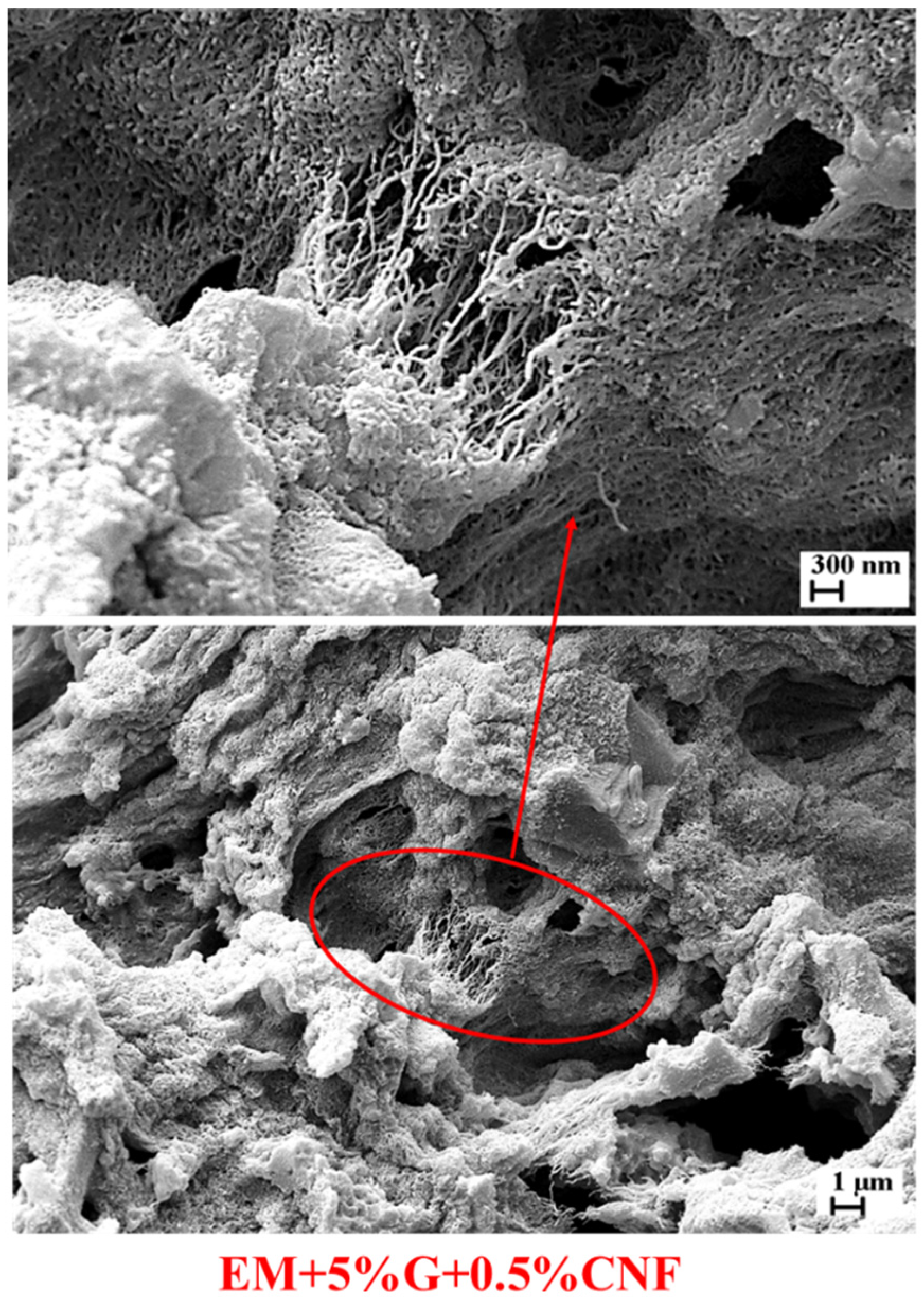
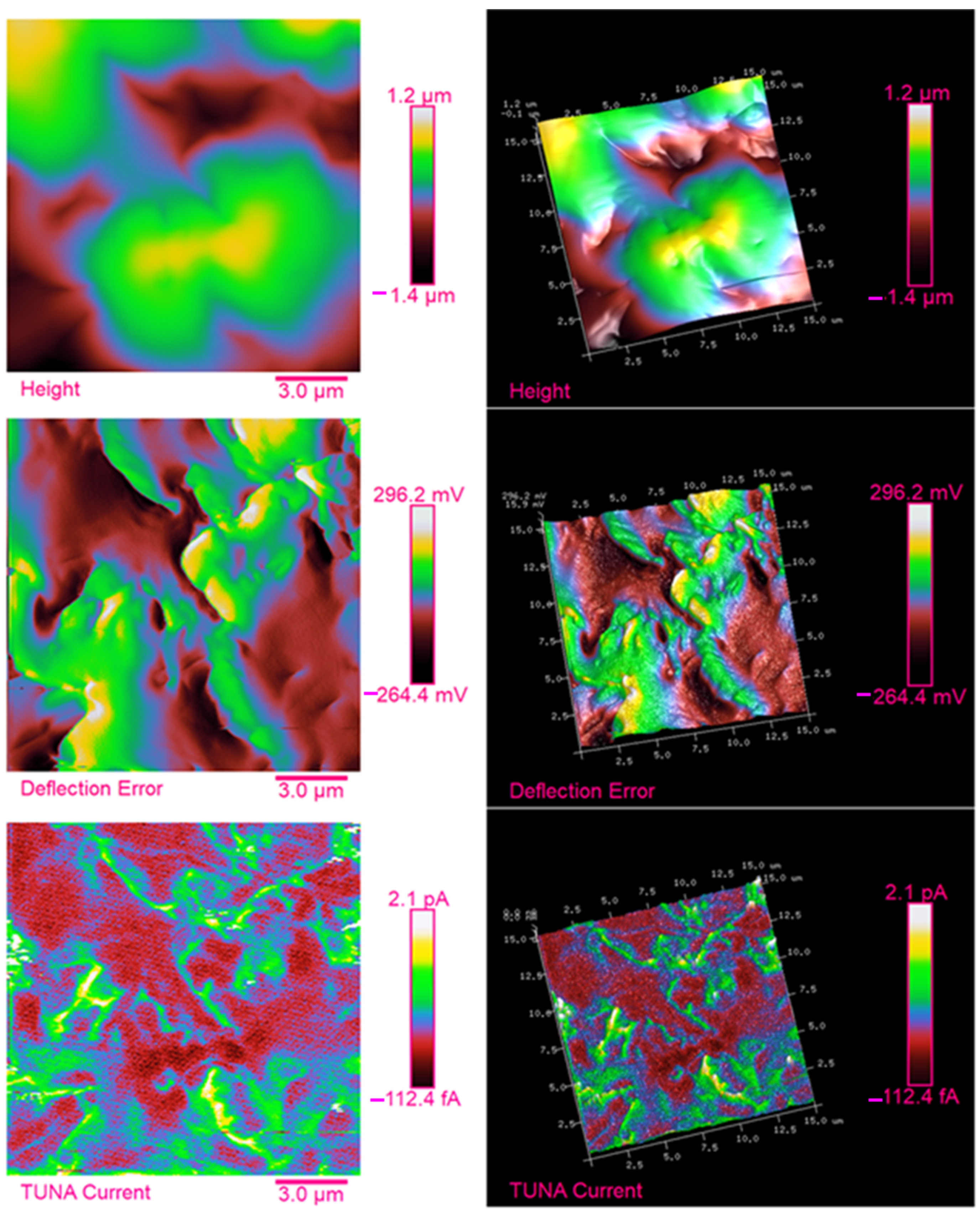
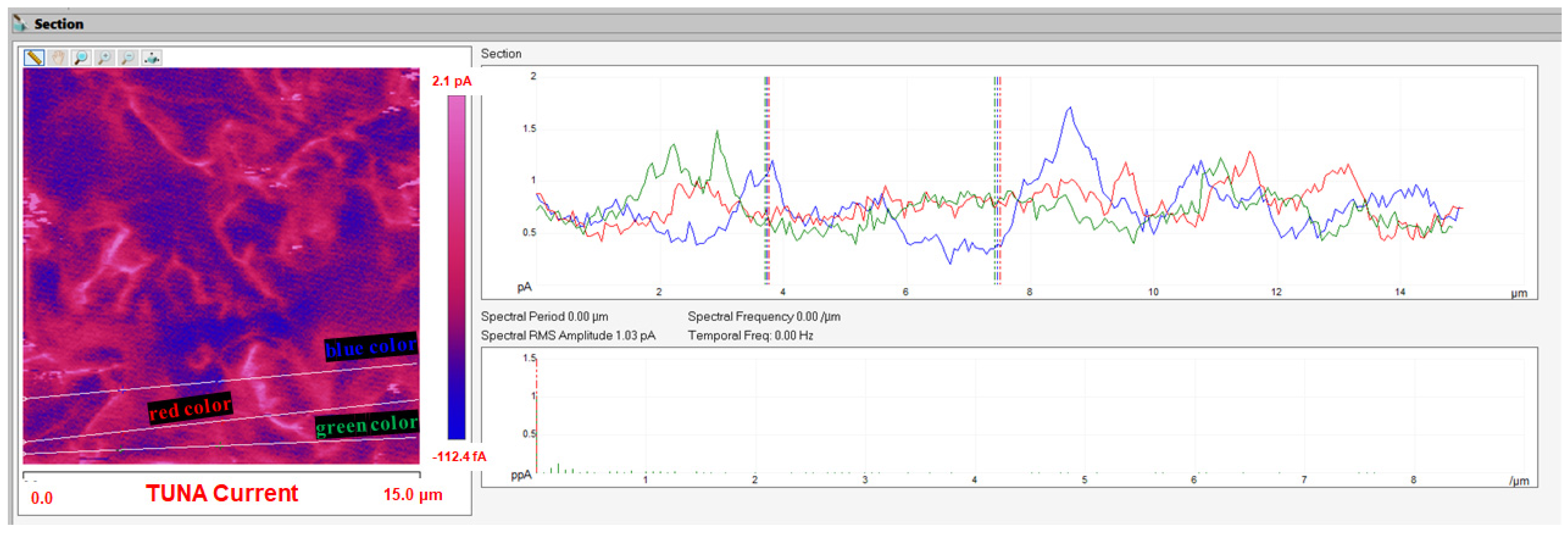
3.4. Morphological Characterization of Carbon Nanofibers and Nanofilled Epoxy Samples

The SEM image of Figure 7 shows the morphological characteristics of the carbon nanofibers used in this work. The carbon nanofibers, as a consequence of the thermal treatment at 2500 °C, exhibit a rigid and straight structure due to the flattening of the CNF graphemic carbonaceous curved layers that have fused, giving rise to a minimum spacing between them. The same carbon nanofibers, when not subjected to high-temperature heat treatment, are characterized by a peculiar morphology called “Dixie Cup” [31]. In order to evaluate the level of dispersion of CNF inside the polymeric matrix both in the absence (EM + 0.5%CNF sample) and in the presence of the flame-retardant molecule GPOSS (EM + 5%G + 0.5%CNF sample), the morphological analysis was carried out by means of SEM.
Figure 8 and Figure 9 exhibit the SEM images at two different magnifications of the fracture surface of specimens EM + 0.5%CNF and EM + 5%G + 0.5%CNF, respectively. By comparing the SEM images of the two nanocomposites, it can be easily seen that the sample containing GPOSS (Figure 9) has a more satisfying distribution of carbon nanofibers than the sample where GPOSS is absent (Figure 8). Furthermore, a continuous network of carbon nanofibers can be detected, which imparts electrical conductivity to both nanocomposites. This conductive network appears especially evident in several dark areas of the SEM images where the etching procedure, consuming the resin surrounding the carbon nanofibers, has allowed them to be exposed. In this regard, it is important to underline that, for the matrix containing GPOSS, the conductive network appears denser, showing a singular interwoven mesh aspect that extends over the entire investigated surface where the nanofibers really appear better dispersed (Figure 9). A crucial role in improving the dispersion of the nanofiller is played by the presence of GPOSS, which lowers the viscosity of the epoxy matrix in which it is solubilized at the molecular level [38,39].
The multifunctional nanocomposite EM + 5%G + 0.5%CNF was subjected to morphological analysis by tunneling atomic force microscopy (TUNA-AFM) in order to evaluate the distribution of the conductive carbon nanofibers (CNF) inside the epoxy resin in the presence of GPOSS solubilized at molecular level. This technique permits a direct correlation of local topography with electrical properties of the nanofilled-based samples [16,19,32] measuring ultra-low currents ranging from 80 fA to 120 pA. In Figure 10, three different types of images, namely height, deflection error and TUNA current, both two-dimensional (2D) and three-dimensional (3D), are shown. They were captured simultaneously when a small tip is used to scan across the same area of the sample. These images allow the reader to have a clear view of the morphological characteristics observed in the light of the complementary information deriving from the three images that help to more easily detect the shape of the structure of the investigated sample. More specifically, the height image is essentially a topographic image shown as a map of pixels of different colors, where a colored bar associates color with height. This type of image allows us to estimate both lateral (X and Y) and vertical (Z) measurements. However, since such “height maps” do not always really resemble the object in question in shape, the topography image is further enhanced by adding the deflection signal to the surface structure. When operating in conditions of constant force, the deflection signal is also referred to as an error signal (“Deflection Error” image) since deflection is the feedback parameter; any characteristic or morphology that appears is due to the “error” in the feedback loop, or rather due to the feedback loop, which must intervene to keep the deflection setpoint constant. The TUNA current image is surprisingly interesting since it allows us to localize the conductive electrical domains at the nanometric scale and to identify the presence of conductive networks within the matrix in which the nanofiller is dispersed, also providing indications on the strength of the interfacial interactions between the nanofiller and the host matrix. From Figure 10, we can easily observe the carbon nanofibers, which constitute the conductive phase of the multifunctional nanocomposite, and which are well dispersed within the polymeric matrix thanks also to the presence of GPOSS, which allows us to reduce the viscosity of the nano-loaded system. All the TUNA images, but in particular the TUNA current pictures, allow us to discriminate a highly cross-linked conductive network that is highlighted by bright and intense colors ranging from light blue to yellow, which are associated with the scale bar shown on the right of the image. For this conductive network that extends along the entire investigated sample surface, local current values ranging from −112.4 fA to 2.1 pA are recorded, which satisfactorily justify the conductive behavior of the nanocomposite EM + 5%G + 0.5%CNF, whose electrical conductivity is 1.35 × 10⁻¹ S/m. This electrical conductivity value is higher than that recorded by the EM + 0.5%CNF sample loaded with the same percentage of carbon nanofibers but without the GPOSS, which is equal to 5.84 × 10⁻² S/m. For the unfilled epoxy formulation EM, as expected, a value of 8.17 × 10⁻¹⁴ S/m was instead recorded, thus confirming its insulating behavior. The action of GPOSS, as a viscosity modulator, results in a better dispersion of the carbon nanofibers within the insulating polymeric matrix with which they are strongly interconnected, forming a conductive nanometric network. In this regard, it is important to underline that the flow current due to the tunneling effect passing along the carbon nanofibers guarantees an effective transfer of the electrical properties to the insulating matrix thanks to the cross-linked conductive structure. In fact, on the whole investigated sample surface, it was possible to record current values as shown by the scale bar observable to the right of the TUNA image. Nanodomains characterized by higher current values are highlighted by the lighter pink-fuchsia colors of the scale bar.
In order to estimate the CNF dispersion in the resin, Figure 11 shows the shape of the current changes visible in green, red and blue colors (see on the right) associated with the three white lines in the TUNA current image (see on the left) of the EM + 5%G + 0.5%CNF sample. We can see a good distribution of the carbon nanofibers within the host matrix. This can be deduced from the fact that the frequency of the changes due to filler/matrix interchanges along the three lines is quite constant, even if we can observe some areas of the sample where the current variations seem greater in correspondence with more conductive electricity.
Using FTIR spectroscopy, we carried out an analysis of the curing behavior of the multifunctional nanocomposite through the variation in the band intensity of the functional groups, first at room temperature (before the curing treatment) and then at the two highest temperatures of 125 °C and up to 200 °C, which correspond to the temperatures programmed for the curing cycle of the investigated samples. In Figure 12, where spectroscopic analysis of the EM + 5%G + 0.5%CNF sample at room temperature and up to 125 °C for different times is reported, and in Figure 13, where the comparison between FTIR curves of the EM + 5%G + 0.5%CNF sample before curing (RT) and after curing (125 °C 1 h and 200 °C 3 h) is shown, the characteristic absorption peak of epoxide group at 908 cm−1 is highlighted in order to observe its evolution during the polymerization reaction of the multifunctional nanocomposite.
The crosslinking kinetics carried out by FTIR allows estimating, starting from the uncured sample at room temperature (RT), a change in the intensity of this signal as a function of the crosslinking time at temperatures of 125 °C up to 200 °C that have been defined for the curing cycle to which the EM + 5%G + 0.5%CNF nanocomposite was subjected. From the FTIR spectra, we can see that the peak of the epoxy group is very pronounced before crosslinking, i.e., at room temperature, remaining up to a temperature of 125 °C for 1 h (see Figure 12), highlighting that the polymerization time up to 1 h did not significantly influence the opening reaction of the epoxy ring. In this paper, the spectroscopic investigation made it possible to investigate the polymerization mechanism of the tetrafunctional precursor TGMDA with the cross-linking agent DDS, whose strong reactivity is attributable to the high nucleophilicity of the nitrogen atom of the amino group, which is characterized by well-defined absorptions. Despite the fact that the N-H stretching is positioned between 3500 and 3300 cm−1, the primary amines present a doublet (indicating the symmetric and antisymmetric stretching modes), while the secondary amines present one single band. From the comparison of the FTIR spectra in Figure 13, we can observe after the curing at 200 °C for 3 h the disappearance of the peak at 908 cm−1 due to C-O stretching of oxirane group and the N-H stretching vibration bands of DDS at 3060–3500 cm−1, indicating the opening of epoxy rings. Therefore, the absence of the aforementioned FTIR signals and presence of the O-H stretch (originating from the attack of NH2 to the epoxide ring) at 3200–3650 cm−1 confirms the conversion of the epoxy group into the corresponding polymer, as well as the completion of the curing process through the chemical reactions that led to the creation of a crosslinked polymeric network. The changes in the intensity of the characteristic infrared signals discussed here are particularly noticeable when compared to the peaks at 1143 cm−1 and 1105 cm−1 related to the strong asymmetric and symmetric SO2 stretching of the DDS hardener [40] and the peaks at 1595 cm−1 and 1515 cm−1 attributable to the phenyl groups [41], which remain unchanged during the curing process.

4. Conclusions

Assuming that the material selection for advanced composites plays a crucial role in the aerospace sector, in this work, we have successfully formulated and characterized a smart epoxy nanocomposite with multifunctional properties capable of simultaneously performing several functions by increasing mechanical performance, flame resistance and electrical conductivity. The synergistic effect of the flame-retardant GPOSS, solubilized at the molecular level, and the conductive carbon nanofibers well dispersed in the aeronautical resin have helped to create a smart nanofilled system potentially effective in meeting many important requirements of aeronautical materials.
In particular, DMA analysis proves that the presence of GPOSS, solubilized at molecular level in the epoxy matrix, leaves the value of the storage modulus almost unchanged in a wide range of temperatures (from 30 °C to 165 °C).
The additional presence of CNFs (0.5 wt%) determines an enhancement in the storage modulus of 700 MPa from −30 °C to 180 °C with respect to the resin matrix and the resin/GPOSS systems. Hence, a value higher than 2700 MPa is detected from 30 °C to 110 °C.
Furthermore, the electrical conductivity of the multifunctional nanocomposite containing both GPOSS and CNFs reaches the value of 1.35 × 10⁻¹ S/m, which is a very satisfying value to contrast the electrical insulating property of the epoxy systems. The tunneling atomic force microscopy (TUNA) technique highlights the electrically conductive network well distributed in the sample. The ignition time of the multifunctional nanocomposite is higher than that of the sample containing GPOSS alone of about 35%.

Author Contributions

Conceptualization, M.R. and L.G.; methodology, M.R., S.P. and A.S.; software, S.P. and A.S.; validation, M.R. and L.G.; formal analysis, M.R. and L.G.; investigation, M.R. and L.G.; resources, M.R. and L.G.; data curation, M.R., S.P. and A.S.; writing—original draft preparation, M.R.; writing—review and editing, M.R.; visualization, M.R. and L.G.; supervision, L.G., S.P. and A.S.; project administration, L.G.; funding acquisition, L.G. All authors have read and agreed to the published version of the manuscript.

Funding

This research was funded with support from the European Union (Horizon 2020—G.A. EU Project 760940-MASTRO).

Institutional Review Board Statement

Not applicable.

Informed Consent Statement

Not applicable.

Data Availability Statement

Data are contained within the article.

Conflicts of Interest

The authors declare no conflict of interest.

References

  1. Vertuccio, L.; Guadagno, L.; Spinelli, G.; Russo, S.; Iannuzzo, G. Effect of carbon nanotube and functionalized liquid rubber on mechanical and electrical properties of epoxy adhesives for aircraft structures. Compos. B Eng. 2017, 129, 1–10. [Google Scholar] [CrossRef]
  2. Soutis, C. 1—Introduction: Engineering requirements for aerospace composite materials. In Polymer Composites in the Aerospace Industry; Irving, P.E., Soutis, C., Eds.; Woodhead Publishing: Cambridge, UK, 2015; pp. 1–18. ISBN 9780857095237. [Google Scholar]
  3. Joshi, M.; Chatterjee, U. 8—Polymer nanocomposite: An advanced material for aerospace applications. In Advanced Composite Materials for Aerospace Engineering; Rana, S., Fangueiro, R., Eds.; Woodhead Publishing: Cambridge, UK, 2016; pp. 241–264. ISBN 9780081009390. [Google Scholar]
  4. Sardiwal, S.K.; Sami, M.A.; Anoop, B.V.S.; Susmita, G.; Vooturi, L.; Uddin, S.A. Advanced Composite Materials in Typical Aerospace Applications. Glob. J. Res. Eng. D Chem. Eng. 2014, 14, 1–7. [Google Scholar]
  5. Das, M.; Sahu, S.; Parhi, D.R. A Review of Application of Composite Materials for Aerospace Structures and its Damage Detection Using Artificial Intelligence Techniques (18 October 2020). In Proceedings of the International Conference on Artificial Intelligence in Manufacturing & Renewable Energy (ICAIMRE), Bhubaneswar, Odisha, India, 25–26 October 2019; Available online: https://ssrn.com/abstract=3714181 (accessed on 18 October 2020). [CrossRef]
  6. Tasca, A.L.; Cipolla, V.; Abu Salem, K.; Puccini, M. Innovative Box-Wing Aircraft: Emissions and Climate Change. Sustainability 2021, 13, 3282. [Google Scholar] [CrossRef]
  7. Chua, M.H.; Smyth, B.M.; Murphy, A.; Butterfield, J. Understanding Aerospace Composite Components’ Supply Chain Carbon Emissions. In Proceedings of the Irish Manufacturing Conference, IMC32, Belfast, UK, 3–4 September 2015; Available online: http://www.qub.ac.uk/sites/imc32/ (accessed on 15 February 2017).
  8. Zhu, L.; Li, N.; Childs, P.R.N. Light-weighting in aerospace component and system design. Propuls. Power Res. 2018, 7, 103–119. [Google Scholar] [CrossRef]
  9. Marino, M.; Sabatini, R. Advanced Lightweight Aircraft Design Configurations for Green Operations. In Proceedings of the Practical Responses to Climate Change 2014 (PRCC 2014), Engineers Australia, Barton, UK, 25–27 November 2014; pp. 1–9. Available online: https://researchrepository.rmit.edu.au/discovery/delivery/61RMIT_INST:RMITU/12247769960001341 (accessed on 22 April 2015).
  10. Ortega Alba, S.; Manana, M. Energy Research in Airports: A Review. Energies 2016, 9, 349. [Google Scholar] [CrossRef] [Green Version]
  11. Costa, P.; Costa, C.M.; Lanceros-Mendez, S. Chapter Fourteen—Functional, lightweight materials: Outlook, future trends, and challenges. In Woodhead Publishing in Materials, Advanced Lightweight Multifunctional Materials; Costa, P., Costa, C.M., Lanceros-Mendez, S., Eds.; Woodhead Publishing: Cambridge, UK, 2021; pp. 503–507. ISBN 9780128185018. [Google Scholar] [CrossRef]
  12. Vertuccio, L.; Guadagno, L.; Spinelli, G.; Lamberti, P.; Zarrelli, M.; Russo, S.; Iannuzzo, G. Smart coatings of epoxy based CNTs designed to meet practical expectations in aeronautics. Compos. B Eng. 2018, 147, 42–46. [Google Scholar] [CrossRef]
  13. Lendlein, A.; Trask, R.S. Multifunctional materials: Concepts, function-structure relationships, knowledge-based design, translational materials research. Multifunct. Mater. 2018, 1, 010201. [Google Scholar] [CrossRef]
  14. Oliwa, R.; Heneczkowski, M.; Oleksy, M.; Galina, H. Epoxy composites of reduced flammability. Compos. B Eng. 2016, 95, 1–8. [Google Scholar] [CrossRef]
  15. Gagné, M.; Therriau, D. Lightning strike protection of composites. Prog. Aerosp. Sci. 2014, 64, 1–16. [Google Scholar] [CrossRef]
  16. Raimondo, M.; Guadagno, L.; Vertuccio, L.; Naddeo, C.; Barra, G.; Spinelli, G.; Lamberti, P.; Tucci, V.; Lafdi, K. Electrical conductivity of carbon nanofiber reinforced resins: Potentiality of Tunneling Atomic Force Microscopy (TUNA) technique. Compos. B Eng. 2018, 143, 148–160. [Google Scholar] [CrossRef]
  17. Raimondo, M.; Naddeo, C.; Vertuccio, L.; Lafdi, K.; Sorrentino, A.; Guadagno, L. Carbon-Based Aeronautical Epoxy Nanocomposites: Effectiveness of Atomic Force Microscopy (AFM) in Investigating the Dispersion of Different Carbonaceous Nanoparticles. Polymers 2019, 11, 832. [Google Scholar] [CrossRef] [PubMed] [Green Version]
  18. Alemour, B.; Bradan, O.; Hassan, M.R. A Review of Using Conductive Composite Materials in Solving Lightening Strike and Ice Accumulation Problems in Aviation. J. Aerosp. Technol. Manag. 2019, 11, e1919. [Google Scholar] [CrossRef]
  19. Raimondo, M.; Guadagno, L.; Speranza, V.; Bonnaud, L.; Dubois, P.; Lafdi, K. Multifunctional graphene/POSS epoxy resin tailored for aircraft lightning strike protection. Compos. B Eng. 2018, 140, 44–56. [Google Scholar] [CrossRef]
  20. Raimondo, M.; Russo, S.; Guadagno, L.; Longo, P.; Chirico, S.; Mariconda, A.; Bonnaud, L.; Murariu, O.; Dubois, P. Effect of incorporation of POSS compounds and phosphorous hardeners on thermal and fire resistance of nanofilled aeronautic resins. RSC Adv. 2015, 5, 10974–10986. [Google Scholar] [CrossRef] [Green Version]
  21. Yang, H.; He, C.; Russell, T.P.; Wang, D. Epoxy-polyhedral oligomeric silsesquioxanes (POSS) nanocomposite vitrimers with high strength, toughness, and efficient relaxation. Giant 2020, 4, 100035. [Google Scholar] [CrossRef]
  22. Harrison, P.G. Silicate cages: Precursors to new materials. J. Organomet. Chem. 1997, 542, 141–183. [Google Scholar] [CrossRef]
  23. Shi, M.; Ao, Y.; Yu, L.; Sheng, L.; Li, S.; Peng, J.; Chen, H.; Huang, W.; Li, J.; Zhai, M. Epoxy-POSS/silicone rubber nanocomposites with excellent thermal stability and radiation resistance. Chin. Chem. Lett. 2022; in press. [Google Scholar] [CrossRef]
  24. Bram, A.I.; Gouzman, I.; Bolker, A.; Atar, N.; Eliaz, N.; Verker, R. Influence of POSS Type on the Space Environment Durability of Epoxy-POSS Nanocomposites. Nanomaterials 2022, 12, 257. [Google Scholar] [CrossRef]
  25. Zhi, M.; Liu, Q.; Chen, H.; Chen, X.; Feng, S.; He, Y. Thermal Stability and Flame Retardancy Properties of Epoxy Resin Modified with Functionalized Graphene Oxide Containing Phosphorus and Silicon Elements. ACS Omega 2019, 4, 10975–10984. [Google Scholar] [CrossRef] [Green Version]
  26. Kannan, R.Y.; Salacinski, H.J.; Butler, P.E.; Seifalian, A.M. Polyhedral oligomeric silsesquioxane nanocomposites: The next generation material for biomedical applications. Acc. Chem. Res. 2005, 38, 879–884. [Google Scholar] [CrossRef]
  27. Tanaka, K.; Chujo, Y. Advanced functional materials based on polyhedral oligomeric silsesquioxane (POSS). J. Mater. Chem. 2012, 22, 1733–1746. [Google Scholar] [CrossRef]
  28. Zhang, W.; Camino, G.; Yang, R. Polymer/polyhedral oligomeric silsesquioxane (POSS) nanocomposites: An overview of fire retardance. Prog. Polym. Sci. 2017, 67, 77–125. [Google Scholar] [CrossRef]
  29. Chua, M.H.; Zhou, H.; Xu, J. Chapter 15—Polymer-POSS hybrid materials as fire retardants. In Polyhedral Oligomeric Silsesquioxane (POSS) Polymer Nanocomposites; Thomas, S., Somasekharan, L., Eds.; Elsevier: Amsterdam, The Netherlands, 2021; pp. 305–332. ISBN 9780128213476. [Google Scholar]
  30. Nobile, M.R.; Raimondo, M.; Lafdi, K.; Fierro, A.; Rosolia, S.; Guadagno, L. Relationships between nanofiller morphology and viscoelastic properties in CNF/epoxy resins. Polym. Compos. 2015, 36, 1152–1160. [Google Scholar] [CrossRef]
  31. Guadagno, L.; Raimondo, M.; Vittoria, V.; Vertuccio, L.; Lafdi, K.; De Vivo, B.; Lamberti, P.; Spinelli, G.; Tucci, V. The role of carbon nanofiber defects on the electrical and mechanical properties of CNF-based resins. Nanotechnology 2013, 24, 305704. [Google Scholar] [CrossRef] [PubMed]
  32. Raimondo, M.; Naddeo, C.; Catauro, M.; Guadagno, L. Thermo-mechanical properties and electrical mapping of nanoscale domains of carbon-based structural resins. J. Therm. Anal. Calorim. 2022; in press. [Google Scholar] [CrossRef]
  33. Benzarti, K.; Colin, X. 12—Understanding the durability of advanced fibre-reinforced polymer (FRP) composites for structural applications. In Woodhead Publishing Series in Civil and Structural Engineering, Advanced Fibre-Reinforced Polymer (FRP) Composites for Structural Applications; Bai, J., Ed.; Woodhead Publishing: Cambridge, UK, 2013; pp. 361–439. ISBN 9780857094186. [Google Scholar] [CrossRef]
  34. Wang, J.; Xue, L.; Zhao, B.; Lin, G.; Jin, X.; Liu, D.; Zhu, H.; Yang, J.; Shang, K. Flame Retardancy, Fire Behavior, and Flame Retardant Mechanism of Intumescent Flame Retardant EPDM Containing Ammonium Polyphosphate/Pentaerythrotol and Expandable Graphite. Materials 2019, 12, 4035. [Google Scholar] [CrossRef] [PubMed] [Green Version]
  35. Bannov, A.G.; Nazarenko, O.B.; Maksimovskii, E.A.; Popov, M.V.; Berdyugina, I.S. Thermal Behavior and Flammability of Epoxy Composites Based on Multi-Walled Carbon Nanotubes and Expanded Graphite: A Comparative Study. Appl. Sci. 2020, 10, 6928. [Google Scholar] [CrossRef]
  36. Mishra, K.; Pandey, G.; Singh, R.P. Enhancing the mechanical properties of an epoxy resin using polyhedral oligomeric silsesquioxane (POSS) as nano-reinforcement. Polym. Test. 2017, 62, 210–218. [Google Scholar] [CrossRef]
  37. Guadagno, L.; Naddeo, C.; Raimondo, M.; Barra, G.; Vertuccio, L.; Russo, S.; Lafdi, K.; Tucci, V.; Spinelli, G.; Lamberti, P. Influence of carbon nanoparticles/epoxy matrix interaction on mechanical, electrical and transport properties of structural advanced materials. Nanotechnology 2017, 28, 094001. [Google Scholar] [CrossRef]
  38. Guadagno, L.; Naddeo, C.; Raimondo, M.; Barra, G.; Vertuccio, L.; Sorrentino, A.; Binder, W.H.; Kadlec, M. Development of self-healing multifunctional materials. Compos. B Eng. 2017, 128, 30–38. [Google Scholar] [CrossRef]
  39. Polydoropoulou, P.V.; Katsiropoulos, C.V.; Pantelakis, S.G.; Raimondo, M.; Guadagno, L. A critical assessment of multifunctional polymers with regard to their potential use in structural applications. Compos. B Eng. 2019, 157, 150–162. [Google Scholar] [CrossRef]
  40. Pretsch, E.; Bühlmann, P.; Badertscher, M. Structure Determination of Organic Compounds Tables of Spectral Data Fourth, revised and enlarged ed.; Springer: Berlin/Heidelberg, Germany, 2009. [Google Scholar]
  41. Cheng, J.; Li, J.; Zhang, J.Y. Curing behavior and thermal properties of trifunctional epoxy resin cured by 4, 4′-diaminodiphenyl sulfone. Express Polym. Lett. 2009, 3, 501–509. [Google Scholar] [CrossRef]
Figure 1. Chemical structure of GPOSS.
Aerospace 09 00222 g001
Figure 2. Heat release rate (HRR) curves of the investigated formulations under a heat flux of 50 kW/m2.
Aerospace 09 00222 g002
Figure 3. TGA curves in air of the epoxy samples isothermally solidified.
Aerospace 09 00222 g003
Figure 4. TGA curves in nitrogen of the epoxy samples isothermally solidified.
Aerospace 09 00222 g004
Figure 5. Storage modulus of the epoxy samples isothermally solidified.
Aerospace 09 00222 g005
Figure 6. Loss factor (tan δ) of the epoxy samples isothermally solidified.
Aerospace 09 00222 g006
Figure 7. SEM image of the carbon nanofibers (CNFs).
Aerospace 09 00222 g007
Figure 8. SEM images at different magnifications of the EM + 0.5%CNF sample.
Aerospace 09 00222 g008
Figure 9. SEM images at different magnifications of the EM + 5%G + 0.5%CNF sample.
Aerospace 09 00222 g009
Figure 10. Two-dimensional (on the left) and three-dimensional (on the right) TUNA pictures of the EM + 5%G + 0.5%CNF sample.
Aerospace 09 00222 g010
Figure 11. Shape of the current changes associated with the TUNA current image of the EM + 5%G + 0.5%CNF sample.
Aerospace 09 00222 g011
Figure 12. Spectroscopic analysis of the EM + 5%G + 0.5%CNF sample at room temperature and up to 125 °C for different times.
Aerospace 09 00222 g012
Figure 13. Comparison between FTIR curves of the EM + 5%G + 0.5%CNF sample before curing (RT) and after curing (125 °C 1 h and 200 °C 3 h).
Aerospace 09 00222 g013
Table 1. LOI, PHRR, and Time-to-Ignition (ti) values of the investigated formulations.
SampleLOI
(%O2) (% ± 1)
PHRR (kW/m2)tig (% ± 2)
(s)
EM27540 ± 8140
EM + 5%G33327 ± 4942
EM + 5%G + 0.5%CNF29506 ± 8254
Table 2. CD values of the epoxy samples isothermally solidified.
SampleCuring Temperature (°C)CD (%)
EM125 °C 1 h + 200 °C 3 h92.7
EM + 5%G125 °C 1 h + 200 °C 3 h90.8
EM + 0.5%CNF125 °C 1 h + 200 °C 3 h100
EM + 5%G + 0.5%CNF125 °C 1 h + 200 °C 3 h90.0
Table 3. Values of thermal degradation temperatures Td5% and Td10%, and the residue at 900 °C.
SampleAir FlowNitrogen Flow
Td5%Td10%Residue at 900 °CTd5%Td10%Residue at 900 °C
EM343373035437511
EM + 5%G350376236337716
EM + 0.5%CNF368377~235737324
EM + 5%G + 0.5%CNF375385436938126
Publisher’s Note: MDPI stays neutral with regard to jurisdictional claims in published maps and institutional affiliations.

