Technical Note

Automatic Balancing for Satellite Simulators with Mixed Mechanical and Magnetic Actuation

1
Department of Industrial Engineering, Alma Mater Studiorum Università di Bologna, Via Fontanelle 40, 47121 Forlì, Italy
2
Interdepartmental Centre for Industrial Research in Aerospace, Alma Mater Studiorum Università di Bologna, Via Baldassarre Carnaccini 12, 47121 Forlì, Italy
*
Author to whom correspondence should be addressed.
Aerospace 2022, 9(4), 223; https://doi.org/10.3390/aerospace9040223
Submission received: 1 March 2022 / Revised: 6 April 2022 / Accepted: 13 April 2022 / Published: 16 April 2022
(This article belongs to the Special Issue Verification Approaches for Nano- and Micro-Satellites II)

Abstract

:
Dynamic spacecraft simulators are becoming a widespread tool to enable effective on-ground verification of the attitude determination and control subsystem (ADCS). In such facilities, the on-orbit rotational dynamics shall be simulated, thereby requiring minimization of the external torques acting on the satellite mock-up. Gravity torque is often the largest among the disturbances, and an automatic procedure for balancing is usually foreseen in such facilities as it is significantly faster and more accurate than manual methods. In this note, we present an automatic balancing technique which combines mechanical and magnetic actuation by the joint use of sliding masses and magnetorquers. A feedback control is employed for in-plane balancing in which the proportional and integral actions are provided by moving the masses, while the derivative action is provided by the magnetorquers. Compared to an earlier implementation by the authors relying on shifting masses only, the novel approach is shown to reduce the in-plane unbalance by an additional 45% on average.

1. Introduction

Adequate on-ground verification is of paramount importance for the successful operation of a satellite attitude determination and control subsystem (ADCS). To this end, dynamic attitude simulators have been used for many decades [1]. Thanks to the increasing popularity of small satellites, attitude simulators are now becoming a very popular tool not only for research but also for education [2].
These facilities need to emulate an almost torque-free rotational motion, which is often achieved by positioning the spacecraft mock-up on a platform sustained by a spherical air bearing. Among the different disturbances affecting the dynamics of spherical air bearings, the gravitational torque is usually the largest [3]. It arises due to the offset between the center of mass (CM) and the center of rotation (CR), which must be minimized. The simplest way to reduce this disturbance is by manual balancing [4], which is very time-consuming (depending on the specific implementation [1]). Automatic balancing overcomes this limit and can improve the offset compensation obtained manually [5,6]. It requires the implementation of an automatic control system capable of moving the center of mass of the platform, which is usually obtained by using actuated shifting masses. The position of the center of mass can be estimated through input-output data processing whenever additional actuators are present on-board the mock-up [7,8] or through a least-squares filter based on the dynamical model [9,10]. Alternatively, a two-step procedure can be implemented, in which in-plane balancing is followed by the estimation and compensation of the vertical offset [11,12]. This approach was followed in [13,14], where an automatic balancing system (ABS) was designed and tested as part of a three-degrees-of-freedom simulator for ADCS verification of CubeSats. The ABS employed three sliding masses independently actuated by three stepper motors. The motors were used for the real-time in-plane balancing algorithm based on proportional-integral-derivative (PID) feedback (step 1), while the third motor alone was used in a subsequent step to compensate for the vertical CM-to-CR offset. This latter was estimated, along with the inertia parameters, through off-line least-squares filtering of the angular velocity data sampled during free platform oscillations (step 2). Indeed, platform balancing is inherently related to inertia identification [15,16,17,18], with the latter usually required to complete the former.
The increasing popularity of attitude simulators for small satellites keeps pushing forward the development of new implementations of ABS [19,20,21,22]. For a recent thorough survey and analysis of existing methods, the reader is referred to [23].
Despite ABS based solely upon shifting masses having been proven to be effective in several works [5,6,11,12,13,19], they do have their own limitations. For example, the motors driving the masses have limited response time, and suffer from backlash. In-plane balancing usually is based on a control system using data provided by an onboard inertial measurement unit (IMU). If the feedback loop includes angular rate measurements, then high-frequency noise from gyros may enter the system, resulting in unwanted mechanical vibration that, in turn, can increase gyro noise amplitude.
By recognizing that most nanosatellites in Earth orbit are equipped with magnetic actuators (e.g., coils or magnetorquers), and many attitude testbeds feature magnetic simulation capabilities (through, e.g., Helmholtz coils), in this work we propose an automatic in-plane balancing method which tries to overcome the above drawback by relying upon a combined mechanical/magnetic actuation through shifting masses and magnetorquers. The core idea is to distribute the required control effort to the two kinds of actuators. The proportional and integral parts are realized by mass displacement, while the derivative/damping part is realized by the magnetic torque originated thanks to the magnetorquers’ dipole. In doing so, smoother positioning for the sliding masses is achieved, which results in a more effective unbalance reduction, as demonstrated by the experimental testing reported in this Note.
The modifications required by the proposed balancing technique with respect to a standard approach based only on shifting masses are minimal, provided that the testbed is equipped with a magnetic field simulator; we thus believe that our results might be profitably exploited in other similar facilities.

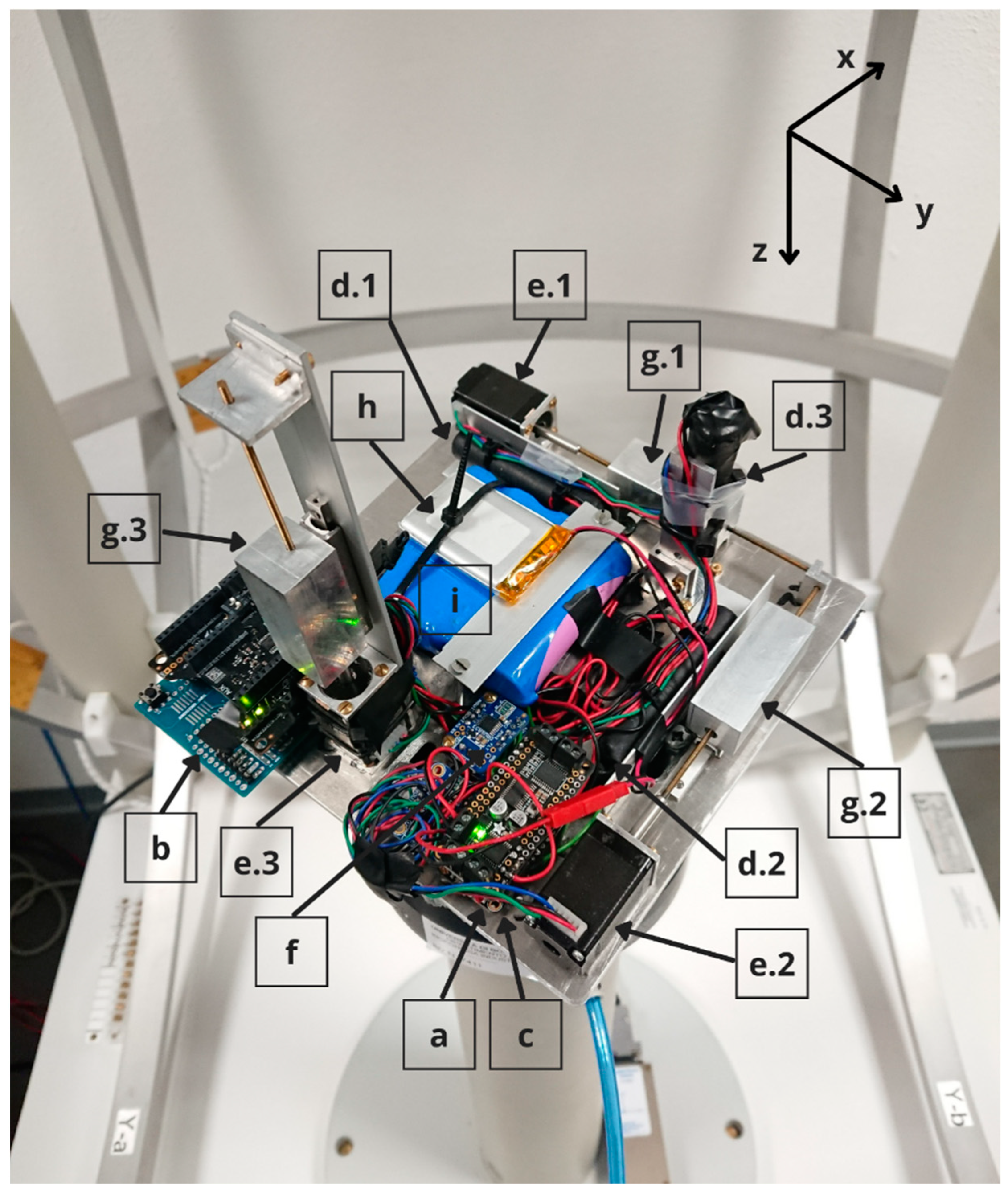
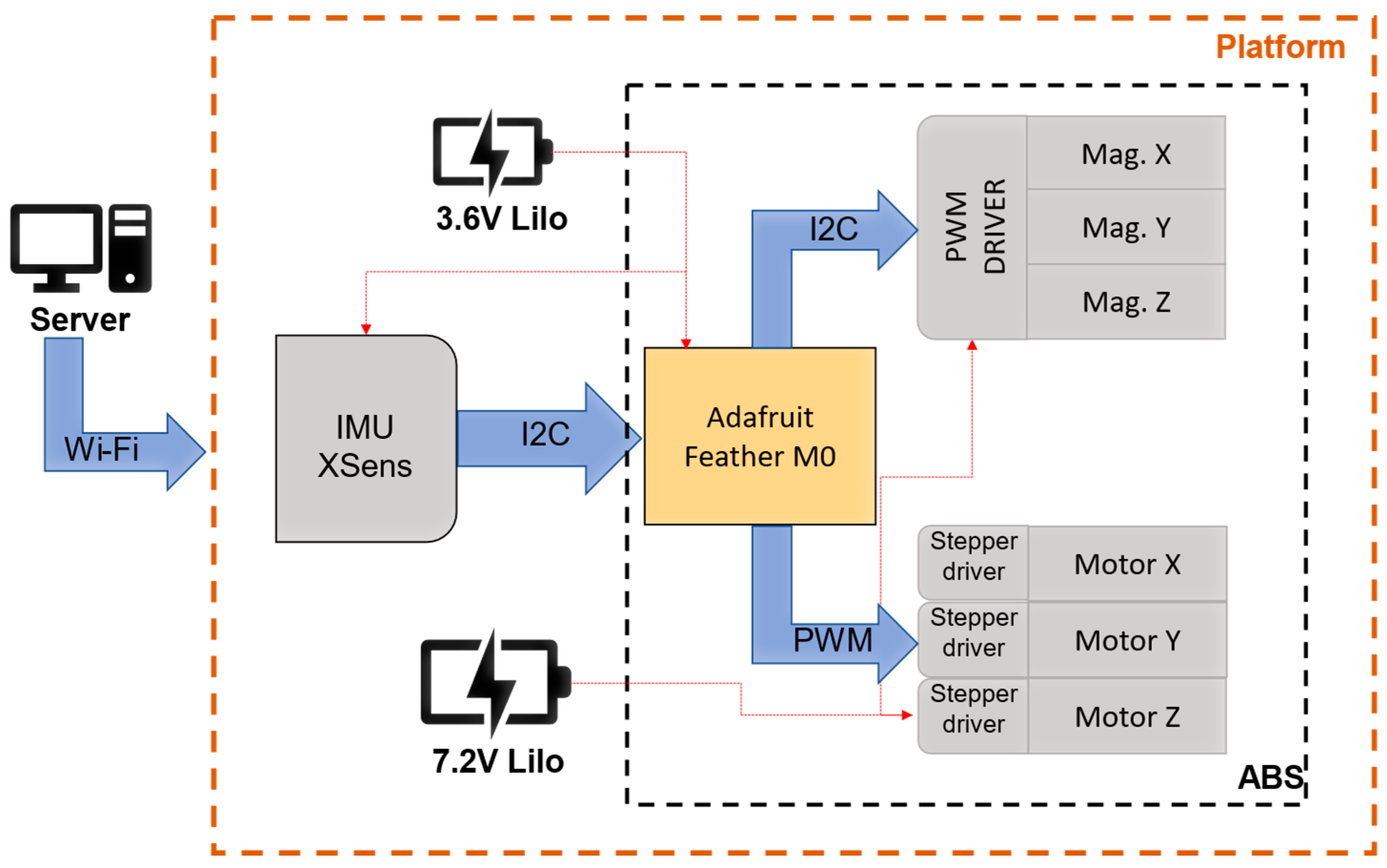
2. Materials and Methods

We adopted as an experimental testbed for the mixed mechanical and magnetic ABS a tabletop rotating platform hosting a CubeSat ADCS mock-up; see Figure 1. The tabletop platform, which is made of amagnetic aluminum, accommodates the mechanics and electronics of the ABS. The mock-up is equipped with a set of three mutually orthogonal magnetorquers, capable of generating 1 Am2 of magnetic dipole each, and with an Arduino Feather M0 microcontroller (item a, following the nomenclature in Figure 1) that communicates through I2C with an XSens MTi-1 IMU (b) and an Adafruit Motor FeatherWing board (c). The FeatherWing board drives the magnetorquers (d.1, d.2, d.3) thanks to a dedicated pulse-width-modulation (PWM) chip. Three stepper motors (e.1, e.2, e.3) are commanded by stepper drivers (f) that are controlled by the M0 microcontroller. Each motor moves a mass of 0.041 Kg (g.1, g.2, g.3) with a minimum step of 2 µm. The IMU and the M0 microcontroller are powered by a 3.6 V Lithium-Ion (LiIO) battery (h), while a 7.2 V LiIO battery (i) powers the three stepper motors and the three magnetorquers.
The overall system architecture is depicted in Figure 2.

Mathematical Model for ABS
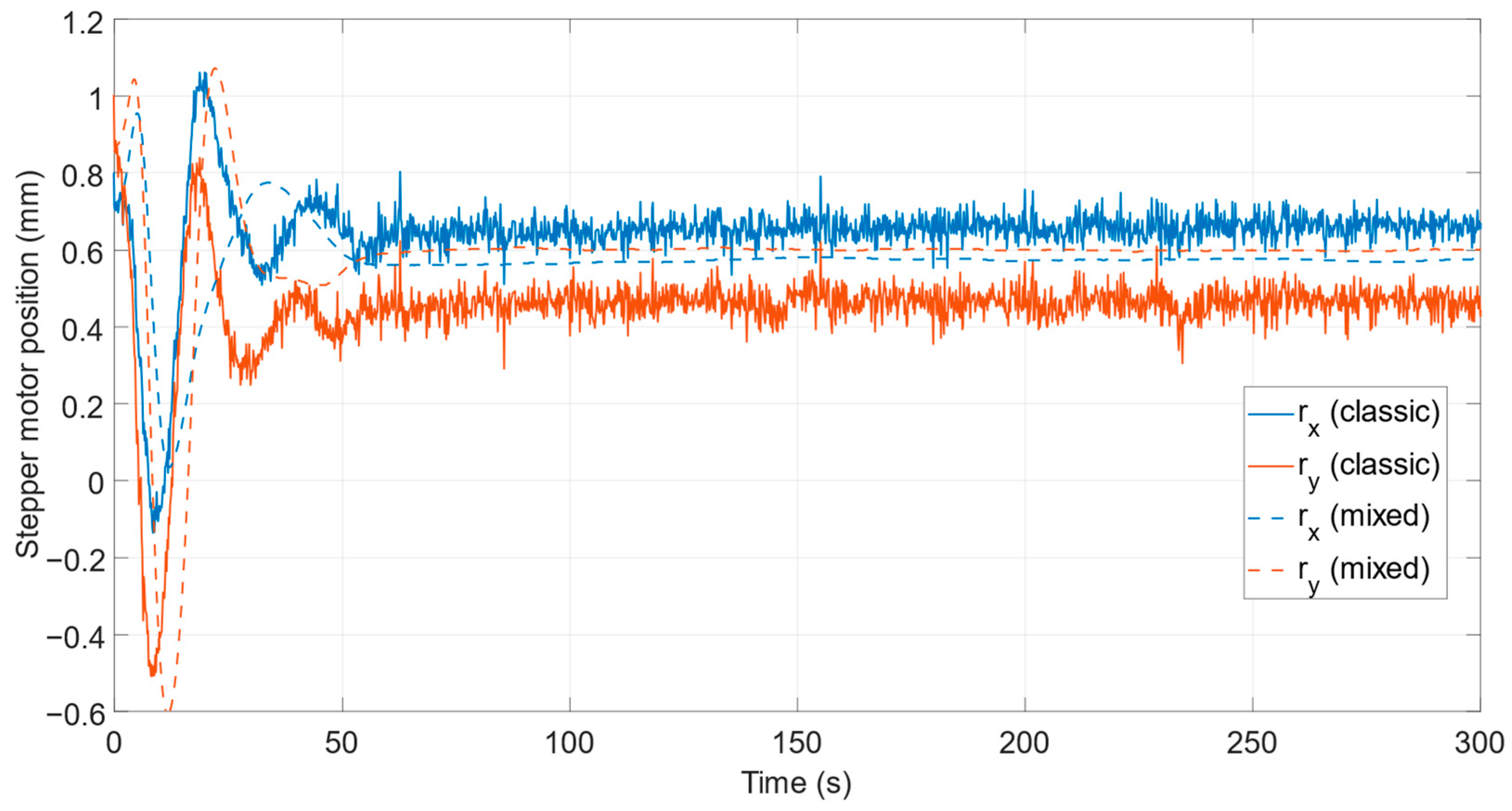
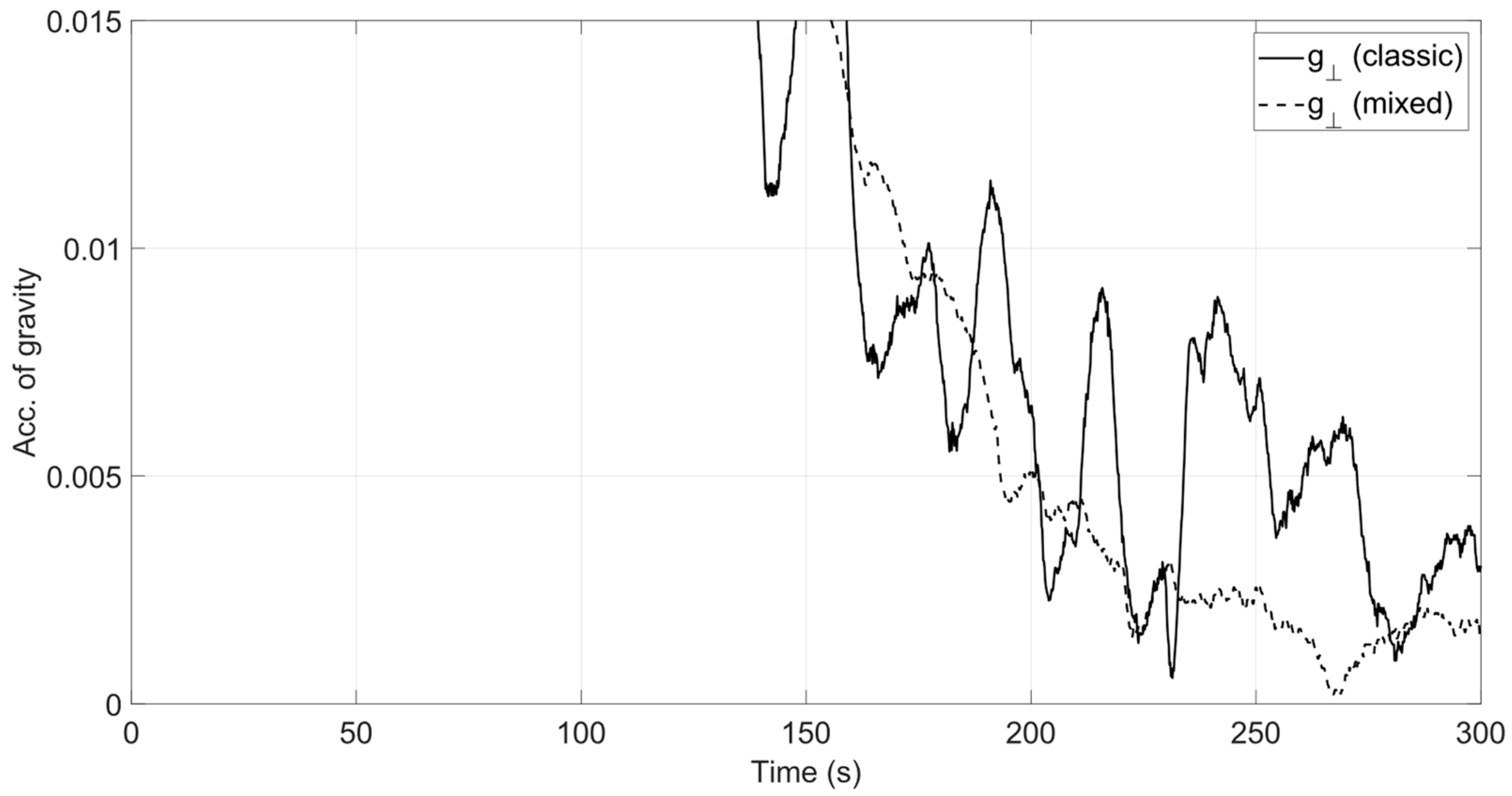
In this work, we focus on the real-time in-plane balancing, which is the first of the two-step procedures developed in [13] and is recalled in the Introduction, whose objective is to align the CM-to-CR offset to the z (out-of-plane) body axis. The main assumptions retained for the mathematical modeling of the system dynamics are the same as described in [13] and will be omitted here for brevity, stating only the main results.
The dynamical system under study is described by [24]:
J x ω ˙ x b + ( J z J y ) ω y b ω z b = m tot ( r CR , y g z b r CR , z g y b ) + τ u , x J y ω ˙ y b + ( J x J z ) ω x b ω z b = m tot ( r CR , z g x b r CR , x g z b ) + τ u , y J z ω ˙ z b + ( J y J x ) ω x b ω y b = m tot ( r CR , x g y b r CR , y g x b ) + τ u , z
where J x , J y and J z are the principal moments of inertia of the inertia matrix that is assumed to be diagonal in the chosen reference frame, ω b = [ ω x b ω y b ω z b ] T is the absolute angular velocity, r CR = [ r CR , x   r CR , y   r CR , z ] T is the CR-to-CM offset, g b = [ g x b g y b g z b ] T is the gravity vector and m tot is the total mass of the free-to-rotate body. In the following, for ease of notation, the superscript b will be omitted. τ u = [ τ u , x   τ u , y   τ u , z ] T is the control torque which, in the envisaged mixed mechanical-magnetic balancing technique, is the sum of two contributions τ s m (mechanical) and τ m a g (magnetic) as in:
τ u = τ s m + τ m a g = r b × m b g + d × b ,
where m b is the sliding mass, r b is the mass displacement vector in body axes, d is the dipole vector created by the set of magnetorquers, and b is the external magnetic field vector, assumed to be controllable (which is the case in our simulator thanks to a Helmholtz cage). In the following, we will assume the external magnetic field b to be anti-parallel to the local vertical (i.e., positive upward).
The desired profiles for the mass displacement r b and the magnetic dipole d will be derived prescribing a control torque according to the following PID feedback law:
τ u = K p g ^ × z ^ K d ω K d K i i , g ^ = g | g | ,   i = ( 0 t   g ^ d ς ) × z ^
whose aim is to align z ^ body axis to gravity by driving g ^ × z ^ to 0. Indeed, if the system converges to an equilibrium for which z ^   and   g ^ are parallel, then the only non-zero component of     r CR must lie along z ^ , which is the definition of planar balancing. In Equation (3), ω and i represent, respectively, the projection of the angular velocity and of the integral error signal i in the plane orthogonal to g ^ .
The contribution to the total torque actuated by the sliding masses τ s m consists of the proportional and integral parts of Equation (3):
τ s m = K p g ^ × z ^ K d K i i .
By comparing the rightmost side of Equation (2) to Equations (3) and (4), the mass displacement which generates the desired τ s m can be computed as [12]:
r b = g ^ × τ s m | g | m b = K p | g | m b [ z ^ K d K i g ^ × ( 0 t g ^ d ς ) × z ^ ]
where z ^ is the projection of z ^ in the plane perpendicular to g ^ . The contribution to the total torque to be actuated by the magnetorquers is instead:
τ m a g = K d ω ,
which is obtained by setting the magnetic dipole d equal to:
d = 1 b b ^ × τ m a g = K d b g ^ × ω ,
where the rightmost side has been derived upon substitution of Equation (6), noticing that g ^ × ω = g ^ × ω .
The planar balancing method based on the joint use of Equations (5) and (7) will be compared to a purely mechanical one, where the control torque in Equation (3) is entirely obtained through mass displacement, i.e., by setting:
r b = g ^ × τ u | g | m b = K p | g | m b { z ^ K d g ^ × [ ω + K i ( 0 t g ^ d ς ) × z ^ ] } ,
which differs from Equation (5) due to the additional derivative damping term.

3. Results

The proposed approach for in-plane balancing has been verified through experiments using the testbed described in Section 2, by making joint use of the actuated masses ( m b = 0.123 kg) and of the magnetorquers according to the control laws in Equations (5) and (7). The required measurements, namely the components of the angular rate and gravity vectors, are obtained from the on-board IMU. Both the measurement and control stages are run at a frequency of 20 Hz. The new methodology is compared to the classic one, Equation (8), by performing several tests according to the following set-up.
We start from a balanced platform which underwent multiple iterations of the two-step algorithm developed in [13]. Before beginning each test, a known offset is created in the horizontal plane by commanding the same fixed position to the sliding masses. The platform would then tilt towards a given rest position which is used as the initial condition. The experiment duration is maintained fixed at 300 s for each batch of tests. During the tests employing the magnetorquers, the Helmholtz cage is set to generate a magnetic field parallel to the local vertical (positive upwards) with a magnitude b = 6 × 10⁻⁴ T.
The two methods are compared in terms of residual torque after balancing the range of the masses’ positions r x , r y and steady-state rms value of the dimensionless gravity vector components g ^ x , g ^ y , g ^ = g ^ x 2 + g ^ y 2 , which ideally should become null when a perfect in-plane balance is achieved. The residual torque is estimated using the method described in [13] by computing the variation of the angular momentum of the free-floating balanced platform. This, in turn, is obtained by evaluating the left-hand-side of Equation (1) using the measured angular rates.
The test conditions and results for two different batches of tests are collected in Table 1 and Table 2. Values reported are averaged across each batch population.
A comparison between the stepper motors’ position in the two cases is shown in Figure 3, while Figure 4 depicts the in-plane components of the dimensionless gravitational acceleration, g ^ . In Figure 5, the dipole generated by the magnetorquers during the balancing procedure is shown.
Figure 6 shows the temporal evolution of the estimated total residual torque after multiple iterations of the two-step procedure using both the stepper motors and the magnetorquers.

4. Discussion

A major difference between the two methods consists in the smoother variation of the sliding masses’ positions when magnetorquers are employed for angular velocity damping, both during transients and upon convergence; see Figure 3. As a result, the peak-to-peak variation of the stepper motor positions once the steady state is reached is reduced. Similarly, the steady-state values of the in-plane components of gravity acceleration are also smaller; see Figure 4.
Although both methods effectively reduce the unbalance, the new mixed mechanical-magnetic technique outperforms the classic one. The performance increase can be appreciated using two indexes. First, for a direct assessment of the in-plane balancing effectiveness, we compare the magnitude of the in-plane component of the dimensionless gravity acceleration upon convergence, g ^ , whose root-mean-square value is smaller by about 45% when adopting the new method. Note that g ^ coincides with | g ^ × z ^ | , the norm of the feedback error signal in Equation (3), thereby providing a direct measure of the controller performance.
Secondly, we consider the magnitude of the overall torque acting on the platform after balancing, which is about 14% smaller on average; see Table 1 and Table 2. Given that the torque magnitude estimated by inspection of the free-floating platform oscillations is the total one (i.e., not only due to unbalance, but also, e.g., due to aerodynamic drag and air-bearing friction), this index provides a mainly qualitative assessment of the improvement brought by the new method and of the adequacy of the experimental platform to emulate low-disturbance rotational dynamics. Multiple balancing iterations can also be performed to further decrease the residual torque acting on the rotating platform. In doing so, the torque norm can be maintained below ≈ 4.3 × 10⁻⁵ Nm during free platform oscillations, as depicted in Figure 6.
In summary, the new mixed mechanical-magnetic actuation strategy, when compared to the mechanical-only one, has brought two advantages to our facility, namely i) more effective in-plane balancing, and ii) a smaller total disturbance torque acting on the balanced platform.

5. Conclusions

In this Note, we have presented an approach to the automatic balancing of dynamic attitude simulators making use of mixed mechanical/magnetic actuation through shifting masses and magnetorquers. The method consists of splitting the balancing torque into two parts: a proportional-integral action, obtained by moving the sliding masses, plus a derivative action obtained through an onboard generated magnetic dipole. When experimentally compared to balancing relying upon sliding masses only, the method presented herein yielded a residual in-plane unbalance that was about 45% smaller, which in turn allowed achieving a reduced value of disturbance torque acting on the balanced platform.

Author Contributions

Conceptualization, D.M. and A.B.; methodology, A.B. and A.C.; software, A.B. and A.C.; investigation, A.C.; writing—original draft preparation, A.C. and D.M.; writing—review and editing, D.M. and A.B.; supervision, D.M. All authors have read and agreed to the published version of the manuscript.

Funding

This research received no external funding.

Institutional Review Board Statement

Not applicable.

Informed Consent Statement

Not applicable.

Data Availability Statement

The data presented in this study are available on request from the corresponding author.

Conflicts of Interest

The authors declare no conflict of interest.

References

  1. Schwartz, J.L.; Peck, M.A.; Hall, C.D. Historical Review of Air-Bearing Spacecraft Simulators. J. Guid. Control Dyn. 2003, 26, 513–522. [Google Scholar] [CrossRef] [Green Version]
  2. Karpenko, S.O.; Ovchinnikov, M.Y. Laboratory Facility for Testing of Micro- and Nanosatellite Attitude Control Systems. Keldysh Inst. Prepr. 2008, 38, 1–32. [Google Scholar]
  3. Kwan, T.H.; Lee, K.M.B.; Yan, J.; Wu, X. An Air Bearing Table for Satellite Attitude Control Simulation. In Proceedings of the 2015 IEEE 10th Conference on Industrial Electronics and Applications (ICIEA), Auckland, New Zealand, 15–17 June 2015; pp. 1420–1425. [Google Scholar]
  4. Fullmer, R. Dynamic Ground Testing of the Skipper Attitude Control System. In Proceedings of the 34th Aerospace Sciences Meeting and Exhibit, Aerospace Sciences Meetings, Reno, NV, USA, 15−18 January 1996; American Institute of Aeronautics and Astronautics: Virginia Reston, VA, USA, 1996. [Google Scholar]
  5. Da Silva, R.C.; Guimarães, F.C.; De Loiola, J.V.L.; Borges, R.A.; Battistini, S.; Cappelletti, C. Tabletop Testbed for Attitude Determination and Control of Nanosatellites. J. Aerosp. Eng. 2019, 32, 04018122. [Google Scholar] [CrossRef] [Green Version]
  6. Young, J. Balancing of a small satellite attitude control simulator on an air bearing. In Proceedings of the Utah Space Grant Consortium Symposium, Salt Lake City, UT, USA, 19 June 1998; pp. 1–7. [Google Scholar]
  7. Schwartz, J.L.; Hall, C.D. System Identification of a Spherical Air-Bearing Spacecraft Simulator. In Proceedings of the AAS/AIAA Space Flight Mechanics Conference, No. AAS 04-122, Maui, HI, USA, 8–12 February 2004. [Google Scholar]
  8. Schwartz, J.L.; Hall, C.D. Comparison of system identification techniques for a spherical air-bearing spacecraft simulator. In Proceedings of the AAS/AIAA Astrodynamics Specialist Conference, Ponce, Puerto Rico, 9–13 February 2003. [Google Scholar]
  9. Thomas, D.; Wolosik, A.T.; Black, J. CubeSat Attitude Control Simulator Design. In Proceedings of the 2018 AIAA Modeling and Simulation Technologies Conference, Kissimmee, FL, USA, 8–12 January 2018; American Institute of Aeronautics and Astronautics: Virginia Reston, VA, USA, 2018. [Google Scholar]
  10. Gavrilovich, I.; Krut, S.; Gouttefarde, M.; Pierrot, F.; Dusseau, L. Robotic Test Bench for CubeSat Ground Testing: Concept and Satellite Dynamic Parameter Identification. In Proceedings of the 2015 IEEE/RSJ International Conference on Intelligent Robots and Systems (IROS), Hamburg, Germany, 28 September–3 October 2015; pp. 5447–5453. [Google Scholar]
  11. Prado, J.; Bisiacchi, G.; Reyes, L.; Vicente, E.; Contreras, F.; Mesinas, M.; Juárez, A. Three-axis air-bearing based platform for small satellite attitude determination and control simulation. J. Appl. Res. Technol. 2005, 3, 222–237. [Google Scholar] [CrossRef]
  12. Chesi, S.; Gong, Q.; Pellegrini, V.; Cristi, R.; Romano, M. Automatic Mass Balancing of a Spacecraft Three-Axis Simulator: Analysis and Experimentation. J. Guid. Control Dyn. 2014, 37, 197–206. [Google Scholar] [CrossRef] [Green Version]
  13. Bahu, A.; Modenini, D. Automatic mass balancing system for a dynamic CubeSat attitude simulator: Development and experimental validation. CEAS Space J. 2020, 12, 597–611. [Google Scholar] [CrossRef]
  14. Bahu, A.; Modenini, D. On-ground experimental verification of magnetic attitude control for nanosatellites. In Proceedings of the 2021 IEEE 8th International Workshop on Metrology for AeroSpace (MetroAeroSpace), Naples, Italy, 23–25 June 2021; pp. 568–573. [Google Scholar] [CrossRef]
  15. Keim, J.A.; Açıkmeşe, B.; Shields, J. Spacecraft inertia estimation via constrained least squares. In Proceedings of the 2006 IEEE Aerospace Conference, Big Sky, MT, USA, 4–11 March 2006. [Google Scholar] [CrossRef]
  16. Kim, D.-H.; Choi, D.-G.; Oh, H.-S. Inertia Estimation of Spacecraft Based on Modified Law of Conservation of Angular Momentum. J. Astron. Space Sci. 2010, 27, 353–357. [Google Scholar] [CrossRef]
  17. Kim, D.; Yang, S.; Lee, S. Rigid body inertia estimation using extended Kalman and Savitzky–Golay filters. Math. Probl. Eng. 2016, 2016, 2962671. [Google Scholar] [CrossRef]
  18. Bellar, A.; Mohammed, M.A.S. Satellite Inertia Parameters Estimation Based on Extended Kalman Filter. J. Aerosp. Technol. Manag. 2019, 11, 1619. [Google Scholar] [CrossRef]
  19. Liu, Y.; Li, L.; Fu, Z.; Tan, J.; Li, K. Automatic Mass Balancing of a Spacecraft Simulator Based on Non-Orthogonal Structure. In Proceedings of the 2016 UKACC 11th International Conference on Control (CONTROL), Belfast, UK, 31 August–2 September 2016; IEEE: Piscataway, NJ, USA, 2016; pp. 1–6. [Google Scholar]
  20. Hua, B.; Chen, L.; Wu, Y.; Chen, Z. A study of PID and L1 adaptive control for automatic balancing of a spacecraft three-axis simulator. Int. J. Intell. Comput. Cybern. 2018, 11, 269–284. [Google Scholar] [CrossRef]
  21. Sharifi, G.; Mirshams, M.; Ousaloo, H.S. Mass properties identification and automatic mass balancing system for satellite attitude dynamics simulator. Proc. Inst. Mech. Eng. Part G J. Aerosp. Eng. 2017, 233, 896–907. [Google Scholar] [CrossRef]
  22. Ousaloo, H.S.; Sharifi, G.; Akbarinia, B. Extended validation of a ground-based three-axis spacecraft simulator model. Proc. Inst. Mech. Eng. Part G J. Aerosp. Eng. 2021, 235, 151–170. [Google Scholar] [CrossRef]
  23. da Silva, R.C.; Borges, R.A.; Battistini, S.; Cappelletti, C. A review of balancing methods for satellite simulators. Acta Astronaut. 2021, 187, 537–545. [Google Scholar] [CrossRef]
  24. De Ruiter, A.H.J.; Damaren, C.; Forbes, J.R. Spacecraft Dynamics and Control: An Introduction; Wiley: Chichester, UK, 2013; ISBN 978-1-118-40332-7. [Google Scholar]
Figure 1. The CubeSat ADCS mock-up and ABS on the air bearing (see text for explanation).
Aerospace 09 00223 g001
Figure 2. Platform architecture.
Aerospace 09 00223 g002
Figure 3. Comparison of the sliding masses’ position in the case of classic balancing (solid line) and mixed balancing (dashed line).
Aerospace 09 00223 g003
Figure 4. Comparison of the projection in the x-y plane of the normalized gravity acceleration in the case of classic balancing (solid line) and mixed balancing (dashed line).
Aerospace 09 00223 g004
Figure 5. Magnetorquers dipole during mixed balancing.
Aerospace 09 00223 g005
Figure 6. External torque acting on the balanced platform after iterated mechanical-magnetic balancing sessions.
Aerospace 09 00223 g006
Table 1. Gravitational acceleration, masses position and residual torque for the first set of tests.
MechanicalMechanical/Magnetic
Initial offset (mm)−0.5 −0.5
Initial angular rateNullNull
Proportional gain Kp (Nm)1 × 10−31 × 10−3
Derivative gain Kd (Nm∙s)1.8 × 10−31.8 × 10−3
Integral gain KdKi (Nm/s)2 × 10−52 × 10−5
No. of tests44
g ^ x steady rms value (-) 3.74 × 10⁻³ 2.15 × 10⁻³
g ^ y steady rms value (-) 5.31 × 10⁻³ 1.54 × 10⁻³
g ^ steady rms value (-)6.49 × 10⁻³ 2.64 × 10⁻³
r x peak-to-peak (mm)0.1780.014
r y peak-to-peak (mm)0.2020.010
r x standard dev. (mm)0.0260.004
r y standard dev. (mm)0.0300.002
Res. Torque (Nm)8.3 × 10⁻⁵ 6.8 × 10⁻⁵
Table 2. Gravitational acceleration, masses position and residual torque for the second set of tests.
MechanicalMechanical/Magnetic
Initial offset (mm)0.5 0.5
Initial angular rateNullnull
Proportional gain Kp (Nm)1 × 10−31 × 10−3
Derivative gain Kd (Nm∙s)1.8 × 10−31.8 × 10−3
Integral gain KdKi (Nm/s)2 × 10−52 × 10−5
No. of tests44
g ^ x steady rms value (-) 2.44 × 10−31.54 × 10−3
g ^ y steady rms value (-) 3.87 × 10−32.71 × 10−3
g ^ steady rms value (-)4.57 × 10−33.12 × 10−3
r x peak-to-peak (mm)0.1420.020
r y peak-to-peak (mm)0.148 0.012
r x standard dev. (mm)0.022 0.004
r y standard dev. (mm)0.024 0.004
Res. Torque (Nm)7.9 × 10⁻⁵ 7.1 × 10⁻⁵
Publisher’s Note: MDPI stays neutral with regard to jurisdictional claims in published maps and institutional affiliations.

