Article

Mission Test Campaign for the EIRSAT-1 Engineering Qualification Model

by
Maeve Doyle
1,2,*,
Rachel Dunwoody
1,2,
Gabriel Finneran
1,2,
David Murphy
1,2,
Jack Reilly
1,2,
Joseph Thompson
2,3,
Sai Krishna Reddy Akarapu
1,2,
Joseph Mangan
1,2,
Sarah Walsh
1,2,
Jessica Erkal
1,2,
Fergal Marshall
1,2,4,
Lána Salmon
1,2,
Eoghan Somers
2,3,
Lily Ha
5,
David Palma
6,
Antonio Martin-Carrillo
1,2,
Sheila McBreen
1,2,
David McKeown
2,3,
William O’Connor
2,3,
Brian Shortt
7,
Alexey Uliyanov
1,2,
Ronan Wall
1,2 and
Lorraine Hanlon
1,2
add Show full author list remove Hide full author list
1
School of Physics, University College Dublin, D04 V1W8 Dublin, Ireland
2
Centre for Space Research, University College Dublin, D04 V1W8 Dublin, Ireland
3
School of Mechanical and Materials Engineering, University College Dublin, D04 V1W8 Dublin, Ireland
4
School of Computer Science, University College Dublin, D04 V1W8 Dublin, Ireland
5
HE Space Operations for European Space Agency, ESTEC, 2201 Noordwijk, The Netherlands
6
Redu Space Services for European Space Agency, ESEC, 6890 Libin, Belgium
7
Future Missions Department, Directorate of Science, European Space Agency, ESTEC, 2201 Noordwijk, The Netherlands
*
Author to whom correspondence should be addressed.
Aerospace 2022, 9(2), 100; https://doi.org/10.3390/aerospace9020100
Submission received: 13 January 2022 / Revised: 4 February 2022 / Accepted: 8 February 2022 / Published: 13 February 2022
(This article belongs to the Special Issue Verification Approaches for Nano- and Micro-Satellites II)

Abstract

:
The compact, standardised form factor of CubeSats allows for the use of commercial off-the-shelf components, reducing traditional barriers to entry, such as cost and development time. More than 1500 of these small spacecraft have been launched in the past 20 years, with improving capabilities that enable a wide range of mission profiles. The Educational Irish Research Satellite, EIRSAT-1, is a CubeSat being developed by a student-led team with goals that span education, technology demonstration and science. A comprehensive mission test plan, in which in-flight conditions are simulated, has been developed for EIRSAT-1 and implemented using an engineering qualification model of the spacecraft. In addition to verifying 41 mission requirements, the successful execution of the mission test plan established that the full satellite system can perform the intended mission. Mission testing also proved to be an invaluable tool to prepare for launch and operations, providing the team with a more complete understanding of the satellite’s expected on-orbit behaviour. This work presents a detailed description of the mission test planning process and implementation, as well as key results and lessons learned. In doing so, this work aims to improve the on-orbit reliability of CubeSats by disseminating resources and good practice around mission testing.

1. Introduction

The capabilities of nanosatellites have been growing rapidly since the first CubeSats were launched in the early 2000s [1]. CubeSats are nanosatellites measured in units (U) of 10 cm × 10 cm × 10 cm, weighing ∼1.3 kg/U [2]. CubeSat designs can extend to multiple U, up to 16U, with the most common being 3U [3,4]. Their small size and standardised form factor drive their popularity, as the resources required to develop a space mission are drastically reduced in comparison to those required to implement traditional, one-off spacecraft.
CubeSats were originally envisaged primarily as educational tools [5,6,7]. However, in the past decade, the capabilities of these low-cost, fast-delivery spacecraft have dramatically increased and their usefulness has been widely recognised beyond academia [1]. CubeSats have been used successfully as technology demonstration platforms [8], in Earth Observation missions [9], as communications relays [10], and for astrophysics [11,12,13].
A challenge to the increasing profile of CubeSats as a mainstream satellite platform has been their historically high failure rate [14]. Although vastly improved since the early 2000s, as of May 2018, only ∼17% of all CubeSats launched had fully achieved their mission objectives, while ∼53% had met most of their primary objectives (some of these missions were still in progress at the time of this study) [3]. Different analyses reach similar conclusions on failure rates, although exact numbers vary depending on the completeness of the CubeSat sample considered and the criteria used to define success [1,15]. Among missions that do not succeed, a common issue is found to be early mission loss, immediately or soon after launch [3,14,16]. In addition to the fact that extensive flight heritage has been achieved only relatively recently, these failure rates can largely be attributed to the disruptive CubeSat design philosophy, where increased levels of risk are accepted to reduce a project’s cost (e.g., by using commercial-off-the-shelf components) and time-scale for implementation. The accelerated schedule can lead to a reduction in the scope of testing performed by CubeSat teams [14]. In a survey of six CubeSat teams, most of those who had conducted extensive levels of system testing experienced mainly nominal on-orbit operations, while the team who had insufficient time to do so failed to establish contact with their satellite [17]. Analyses of CubeSat failures have also shown that a significant fraction of such cases could likely have been identified and avoided by more comprehensive system-level functional testing before launch [14,16,18]. The primary use of CubeSats as educational tools and for building capability at institutional or national levels [19], where expertise in satellite development may be limited, is also a contributory factor as university-led projects are typically found to experience higher rates of failure compared to, for example, those from industry [14,20].
Functional tests, which are carried out under both ambient and environmental conditions, are used to significantly reduce risk by demonstrating that a CubeSat can satisfy mission requirements and survive the space environment while doing so [21,22,23]. In this context, environmental conditions are generally simulated through vibration, thermal vacuum (TVAC) and radiation testing of individual subsystems and/or the full satellite system [21,22,23,24,25]. Mission tests, in which end-to-end mission scenarios are simulated in a ‘test as you fly’ approach, where the mission is operated in a flight-equivalent state prior to launch, can further reduce risk by verifying long-term performance requirements and operational scenarios (Section 3).
The aim of this work is to support CubeSat teams wishing to implement mission testing by documenting in detail the mission tests developed and performed for EIRSAT-1. Section 2 provides a brief description of the EIRSAT-1 mission to give context for mission testing, an introduction to which is given in Section 3. In Section 4, a detailed description of the mission test plan developed for EIRSAT-1 is presented. Section 5 discusses key results and lessons learned from implementing this plan during a test campaign with an engineering qualification model of EIRSAT-1, and future plans are reviewed in Section 6.
This work presents an in-depth account of the development and implementation of a mission test plan using EIRSAT-1 as a case study, providing resources and examples that are not widely available in the current literature. The overarching goal of this and previous work [17] is to contribute to the improved reliability of CubeSats, in particular, university-class CubeSats.

2. EIRSAT-1 in a Nutshell

EIRSAT-1, shown in Figure 1, is a 2U CubeSat being implemented by a student-led team at University College Dublin (UCD) [26]. The project to design, build, test and launch this CubeSat as Ireland’s first satellite is supported by the Education Office of the European Space Agency (ESA), under the 2nd round of the Fly Your Satellite! (FYS!) Programme [27].
As the first Irish satellite, one of the main objectives of the EIRSAT-1 mission is to enhance the capabilities of the national higher education sector in space science and engineering. The project also has a number of technology demonstration and scientific aims [26], to be realised by three novel payloads that have been developed in house. The ‘ENBIO Module’ (EMOD) is a thermal materials experiment [28,29], ‘Wave-Based Control’ (WBC) is a software-based attitude control test-bed [30], and the ‘Gamma-ray Module’ (GMOD) is a miniaturised γ -ray detector [31,32] that will observe high-energy radiation from astrophysical phenomena known as gamma-ray bursts (GRBs) [33].
The EIRSAT-1 spacecraft consists of custom hardware that has been designed and developed for both the GMOD and EMOD payloads and the antenna deployment module (ADM) [34], along with commercial off-the-shelf (COTS) components supplied by AAC Clyde Space [35]. All of the COTS components have flight heritage. This includes the battery, electrical power system (EPS), UHF/VHF radio frequency (RF) communications component (CMC), attitude determine and control system (ADCS), and an on-board computer (OBC), which acts as the main flight computer. In addition to firmware supplied with these COTS components, key parts of the flight software have also been developed in house [36,37].
Two versions of the spacecraft are being built—an engineering qualification model (EQM) and a near-identical flight model (FM) [21]. Once built, each model is subject to a series of rigorous tests, which are required to be undertaken by all teams participating in the FYS! Programme. Although significant guidance is received from FYS!, defining the details of test implementation is the responsibility of each team. With the aim of reducing project risk, significant resources have been invested into developing an extensive mission test plan for EIRSAT-1 [17].

3. Mission Testing

Summarising the European Cooperation for Space Standardisation (ECSS) description [38]:
During a mission test, in-flight operational scenarios, including scenarios that call for both standard and contingency procedures, are to be simulated in a mission representative manner. These scenarios should cover the entire mission profile, and should be simulated in the actual flight sequence as part of an uninterrupted test (i.e., the spacecraft should not be powered down between scenarios).
In addition to requirement verification, mission testing is used to validate that the system can perform the intended mission using the ‘test as you fly’ approach. While ‘day-in-the-life’ (DITL) testing adopts a similar approach with similar aims, DITL test time frames are typically much shorter and focus on the first hours to day(s) of operation [39]. Mission testing addresses potential issues related to the actual on-orbit operation of the satellite, for example in the sequencing or duration of operations. As a result, mission testing uniquely reduces risk and builds confidence in the long-term on-orbit reliability of the spacecraft and its operations. Despite these advantages, mission testing is not always performed by CubeSat teams and when it is, the scope of the tests performed varies significantly [17]. This is likely driven by several factors, including: (1) to facilitate a low-cost, fast-delivery CubeSat project, mission testing is not always within scope [40]; (2) implementing a mission representative test requires significant resources to plan and execute; (3) although mission testing (or, at a minimum, DITL testing) is carried out by some CubeSat teams [41,42,43], there is limited information in the literature on the details of the testing performed that can be used as a reference by other CubeSat projects.

4. EIRSAT-1 Mission Test Overview

Mission test plans were developed for EIRSAT-1 over the course of several months. These were shaped initially by inputs from FYS!, who provided general support and also held relevant workshops and seminars (e.g., a series of mission planning and operations seminars led by ESA’s OPS-SAT team [44]). A literature review was additionally conducted, which led to a widely disseminated survey being carried out on CubeSat mission testing [17]. Extensive discussions with experts in the field (e.g., CubeSat hardware and software suppliers) further informed the planning phase. Later development of the test plans was then also advanced by a series of day-long, ‘mock’ mission tests, led by EIRSAT-1’s Operations Team.
Incorporating mission representative constraints, such as communication and power restrictions, along with an extensive range of scenarios, introduces a significant level of complexity. Therefore, in addition to providing details of the simulated scenarios and constraints (Section 4.1), details of the schedule (Section 4.2), personnel (Section 4.3), documentation (Section 4.4), tools (Section 4.5) and setup (Section 4.6) used to conduct EIRSAT-1’s mission tests will also be provided in this work. An overview summarising the mission test organisation to be described in these sections is given in Figure 2.

4.1. Mission Scenarios and Constraints

EIRSAT-1’s mission test plan is composed of more than 20 well-defined simulated scenarios that address both nominal and off-nominal behaviour that may occur on orbit. In this context, a scenario is defined as a set of events or circumstances that impact the mission and/or plan for mission operations. These scenarios were largely shaped by the mission requirements, considering what must be achieved on orbit to meet the requirements, and when they must be satisfied. Similar exercises had previously been completed, for example, when designing the flight software’s separation sequence and mode management routines [36]. Additionally, the off-nominal scenarios were developed to test and de-risk situations that rely on EIRSAT-1’s methods of fault detection, isolation and recovery (FDIR). For instance, these methods include watchdog timers, an automatically triggered ‘safe’ mode/configuration (in which only vital functionality is enabled), low-voltage protections, and on-orbit reprogramming capabilities.
Table 1 presents a subset of the scenarios along with their objectives. The complete set is presented in Appendix A. Out of all possible in-flight scenarios, the scenarios given in this appendix were chosen as: (1) scenarios known or highly likely to be required to operate the mission; (2) scenarios that consider off-nominal circumstances that present a high risk of mission loss or that are likely to occur at some point during the mission lifetime.
The objectives defined for each scenario should ideally be achieved during the mission test, otherwise there is a risk of mission loss if similar scenarios were to be encountered on orbit. To help determine whether the objectives have been achieved, lower-level, more mission-specific pass/fail criteria have also been defined, encompassing more than 40 mission requirements (out of a total ∼350 requirements, the remainder of which are verified through other means of testing, inspection, etc. [21,45]). The breakdown of scenario objectives into pass/fail criteria, incorporating mission requirements, is demonstrated in Figure 3.
The aim of scenarios 1–5 in Table 1 is to simulate ground-based, pre-launch preparations through to the launch and early operations phase (LEOP), a phase which typically presents significant risk of mission loss [3]. This includes deployment, initial acquisition of signal (AOS) and commissioning. In line with the ECSS definition of mission testing [38], these scenarios are simulated in the expected in-flight sequence.
The other scenarios shown in Table 1 (and listed in full in Appendix A) include nominal and off-nominal scenarios that could occur at some point during the mission lifetime. In EIRSAT-1’s test plans, these nominal scenarios occur during the test as part of normal mission planning. In contrast, the off-nominal scenarios are injected into the test in a more unpredictable manner in terms of the ordering in which and when they occur. To realistically simulate the occurrence of most off-nominal scenarios on orbit, where the timing and nature of an issue cannot be foreseen, the order of these scenarios is exclusive knowledge to only a subset of test operators who are responsible for fault injection during the mission test (see Section 4.3).
In addition to the scenarios listed in Appendix A, additional unplanned scenarios that are non-critical (i.e., that do not directly result in mission loss), for example, scenarios resulting from some unanticipated spacecraft behaviour, are allowed within the mission test plan. As the inclusion of unplanned scenarios can yield interesting results (e.g., an unforeseen flaw in the plan for operations), they are treated as a vital part of the test. This aspect of the test plan was initially motivated by lessons learned from other CubeSat teams with on-orbit experience [17]:
‘Do not assume that testing covers all scenarios, test what happens when things break down unexpectedly and see if the satellite can recover.’
As well as the scenarios, other key aspects of real on-orbit conditions are also incorporated into the mission test plan [17], including:
  • Power Constraints—The spacecraft’s charging status is based on the expected on-orbit charging profile. For a ∼400 km low Earth orbit (LEO), this profile cycles between 45 min in sunlight (i.e., charging) and 45 min in eclipse (i.e., discharging).
  • Communication Constraints—The constraint of limited two-way communications between a Dublin-based ground station (53.3083  N, 6.2237  W [46]) and a spacecraft in LEO is imposed. This limits two-way communication to 4–5 ‘communication passes’ per day, each lasting ∼4–7 min and separated by ∼1.5 h, before a long gap to the next pass.
  • Inaccessibility—Interaction with the spacecraft that would not be possible on orbit is not normally permitted. In addition to restricting the timing of mission control and data acquisition to ∼minutes-long communication passes, the type of data (and information in general) that are accessible are also restricted to match what would be available on orbit. For example, assessing the state of the spacecraft visually or via debug data output by the flight software over a serial link through the test umbilical are not permitted. However, limited test operator interaction is allowed for fault injection as part of the off-nominal scenarios, as described in Section 4.3.
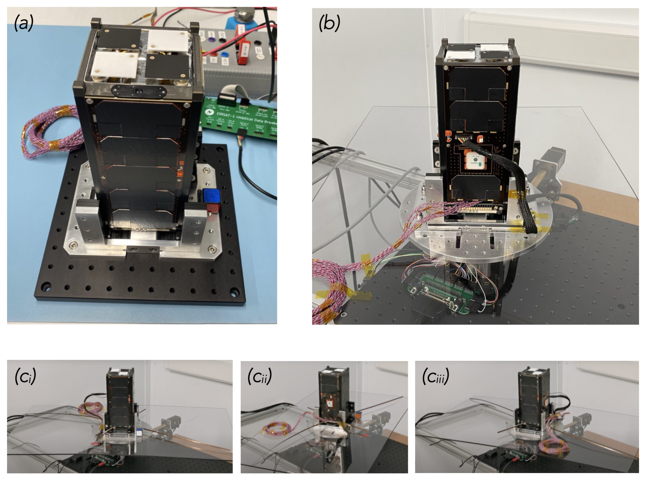
  • Representative physical conditions—Some physical conditions of scenarios are simulated. For instance, the rig on which the spacecraft is seated during the test (described in Section 4.6) can be configured to rotate to mimic conditions when increased spin rates are experienced (e.g., post-launch tumbling).
  • Use of mission tools—Documentation and tools developed for real on-orbit operation of EIRSAT-1 (e.g., the Operations Manual and the Mission Control GUI, which are described in Section 4.4) are included in the mission test plan where possible.

4.2. Test Schedule

A long test duration is a key feature of the mission test campaign, given the notable failure rate of CubeSats during early operations [3]. A lengthy, uninterrupted, test builds confidence in the long-term behaviour of the system in a way that is not typically within the scope of other ground-based testing.
Three to four weeks (running 7 days a week) are nominally scheduled to carry out the mission test described in this work, with approximately the first week allocated mainly to executing the consecutive scenarios 1–5. The test duration is primarily driven by the two-way communication times, where only 4–5 communication passes are scheduled to occur during each working day. The team is not scheduled to be working ‘out of hours’ during the campaign. For practical reasons, pass times are configured such that the first pass starts between 9:00 and 11:00 UTC each day, so the long wait between passes occurs overnight.

4.3. Test Operators

A number of test operator roles have been defined to implement the mission test. These roles and their key responsibilities are described in Table 2. The test operator roles include those that will be required for real on-orbit operations (i.e., spacecraft operators, on-call operators and pass planners), as well as roles solely required to facilitate the test, such as the test coordinator.
The number of each operator required at a time is also given in in Table 2. Given the limited person-power resources that may be available, it is worth noting that not all operators are needed to actively participate in the test activities at all times. For instance, the test coordinator only needs to communicate with the test support operators a couple of times throughout the mission test, to state which of the off-nominal scenarios should be simulated, and their timing. Furthermore, as Table 2 suggests, multiple roles may be held by a single person at a time.

4.4. Test Documentation

Extensive test documentation is required to provide instructions for the operators. Operators must also maintain ‘as-run’ documents throughout the test. These are essential reference documents for post-test reviews, report generation, anomaly investigations, and for establishing the final mission test result. Key documents developed for EIRSAT-1’s EQM mission tests are described in this section.

4.4.1. Test Specification and Procedure

As is standard practice for any testing in which formal requirement verification occurs [39], test specification (TS) and test procedure (TP) documents were developed. The TS provides a detailed description of all aspects of the mission test plan. The supporting TP provides step-by-step instructions for implementing the plan from the point of view of the test support operator (i.e., providing instructions to invoke a scenario or simulate the spacecraft’s would-be on-orbit response) and provides details of any required use of ground support equipment (GSE), as well as information on the actions that spacecraft operators are expected to take in response to each of the scenarios.
A snippet of EIRSAT-1’s mission test TP is shown in Figure 4. In addition to step-by-step instructions, this figure shows that the TP is also formatted to capture results, with additional space provided below each step, as well as a close-out table addressing the scenario’s overarching pass/fail criteria.
As the TP provides exclusive information on the test’s progress and the spacecraft’s state, which would not be known during real on-orbit operations, the test support operators are the only operators to have access to this document during the running of the mission test. As a result, recording the as-run results, during or immediately after each scenario, is solely the test support operator’s responsibility. This, therefore, requires the test support operators to also observe the actions of the spacecraft operators, to ensure they respond as expected when faced with the events of each scenario.
The section of the TP to be followed at any one time is determined either by the set sequence of LEOP or nominal mission planning scenarios, or by instruction from the test coordinator to inject an off-nominal scenario into the test.

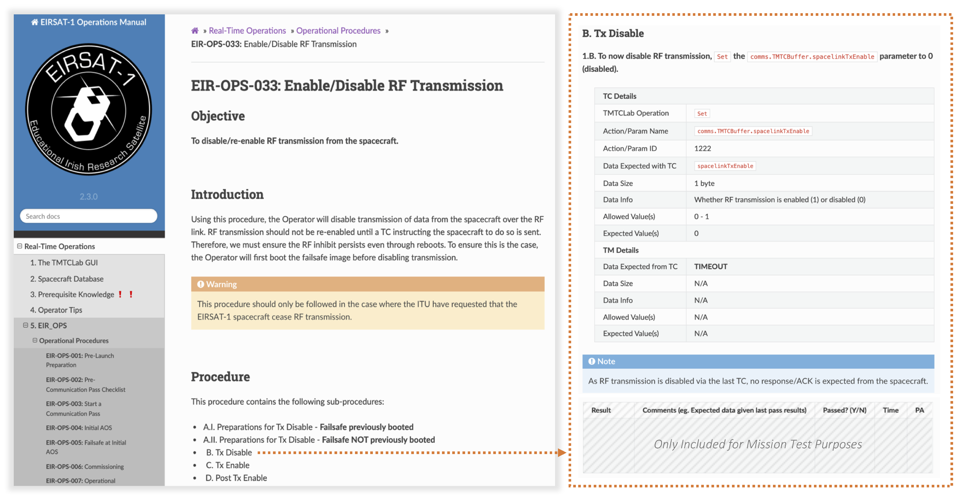
4.4.2. Operations Manual

As shown in Figure 4, the TP includes information on the actions that the spacecraft operators are expected to take during each scenario. However, as the spacecraft operator role is defined to mimic the role of real mission operators during actual on-orbit operations, these operators are not instructed by documents defined solely for testing purposes, such as the TP. Instead, their actions are defined as procedures in the EIRSAT-1 Operations Manual [47], or ‘EIR_OPS’. The manual explains in detail the telecommands (TCs) to send and the telemetry (TM) to expect when carrying out a specific procedure. Both nominal and contingency procedures have been developed, such as
  • EIR-OPS-011: Downlink Data From Storage;
  • EIR-OPS-016: Upload a New Payload Image;
  • EIR-OPS-030: Power Cycle the Spacecraft.
A complete list of these procedures is given in [47].
The EIRSAT-1 Operations Manual has been developed using Sphinx [48], a Python tool widely used for generating documentation in several formats, including HTML and LaTeX/PDF. A sample of HTML output from EIR_OPS is shown in Figure 5.
Most of the actions that spacecraft operators need to take to manage the mission are described in this manual. To effectively use EIR_OPS, operators must be familiar with the objectives of each procedure, understanding which procedure to follow, and when.
The EIR_OPS document is being developed by EIRSAT-1’s Operations Team for the mission itself, and not just for test purposes. As a result, the standard EIR_OPS version is not formatted to capture as-run information. Therefore, for the mission test, another version of the manual is generated as a PDF, which is identical except for added comment boxes included below each step, within which as-run test results can be recorded (Figure 5). The spacecraft operators are responsible for maintaining these as-run records during the mission test.

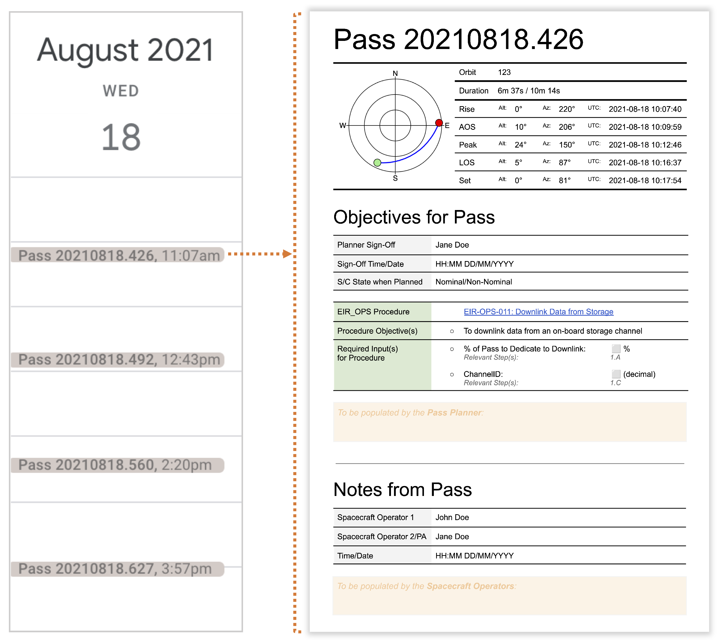
4.4.3. Pass Calendar and Plans

To guide the spacecraft operators as to which of the EIR_OPS procedures to follow during passes, documents referred to as ‘Pass Plans’ are created. These are implemented as Google Docs, and are shared via a Google Calendar. The standard format of a pass plan is shown in Figure 6. YYYYMMDD.XXX is the convention used to identify passes, where XXX represents the pass start time as a decimal fraction of the 24 h day.
To generate calendar events and pass plans for each pass, and link the plans to the calendar events, Python tools that make requests to the Google Calendar/Docs API are used [49,50]. Required information on pass times is calculated using Skyfield [51], a Python tool that computes positions for the stars, planets, and satellites in orbit around the Earth.
During the mission test, members of the team assigned as pass planners are responsible for populating the pass plans, at the latest, the evening before the day the pass occurs. The EIR_OPS procedures to be followed by the spacecraft operators must be specified, as well as any additional input needed for the procedures. The plans include either procedures required to invoke some nominal scenario (the pass planners are made aware of the nominal scenarios to be completed during the mission test), or procedures to deal with off-nominal scenarios. As off-nominal scenarios can occur at any time during the mission test, spacecraft operators are permitted to update pass plans if contingency procedures are required.
The pass plan also includes a section for post-pass notes, as Figure 6 shows. The spacecraft operators are responsible for populating these sections with details on the last known state of the spacecraft (based on the TM from the pass), the activities completed during the pass, as well as any other noteworthy events/observations that might be relevant to future operations. In contrast to the as-run TP and EIR_OPS documents, which serve solely as records of the test activities and results, these notes also aim to encourage the spacecraft operators to perform the type of analyses and critical thinking that will be required post-passes during real on-orbit operations.

4.5. Test Tools

This section describes additional key tools required to support implementation of the mission test plan.
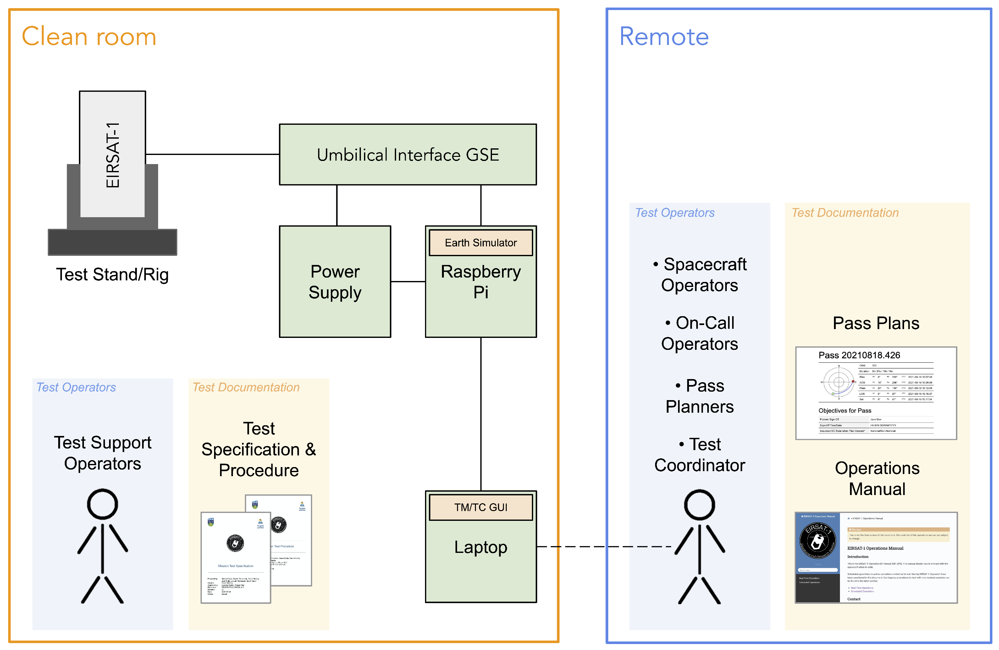
  • Mission Control Tool—A ground station GUI that provides a user-friendly interface to the flight software. This GUI allows operators to easily access all possible TCs using a tree-like view of the read/write parameters and callable functions available in the flight software running on EIRSAT-1’s OBC [36]. Basic TM parsing also allows the operators to see the spacecraft’s responses to TCs. This tool will also be used for in-flight operations.
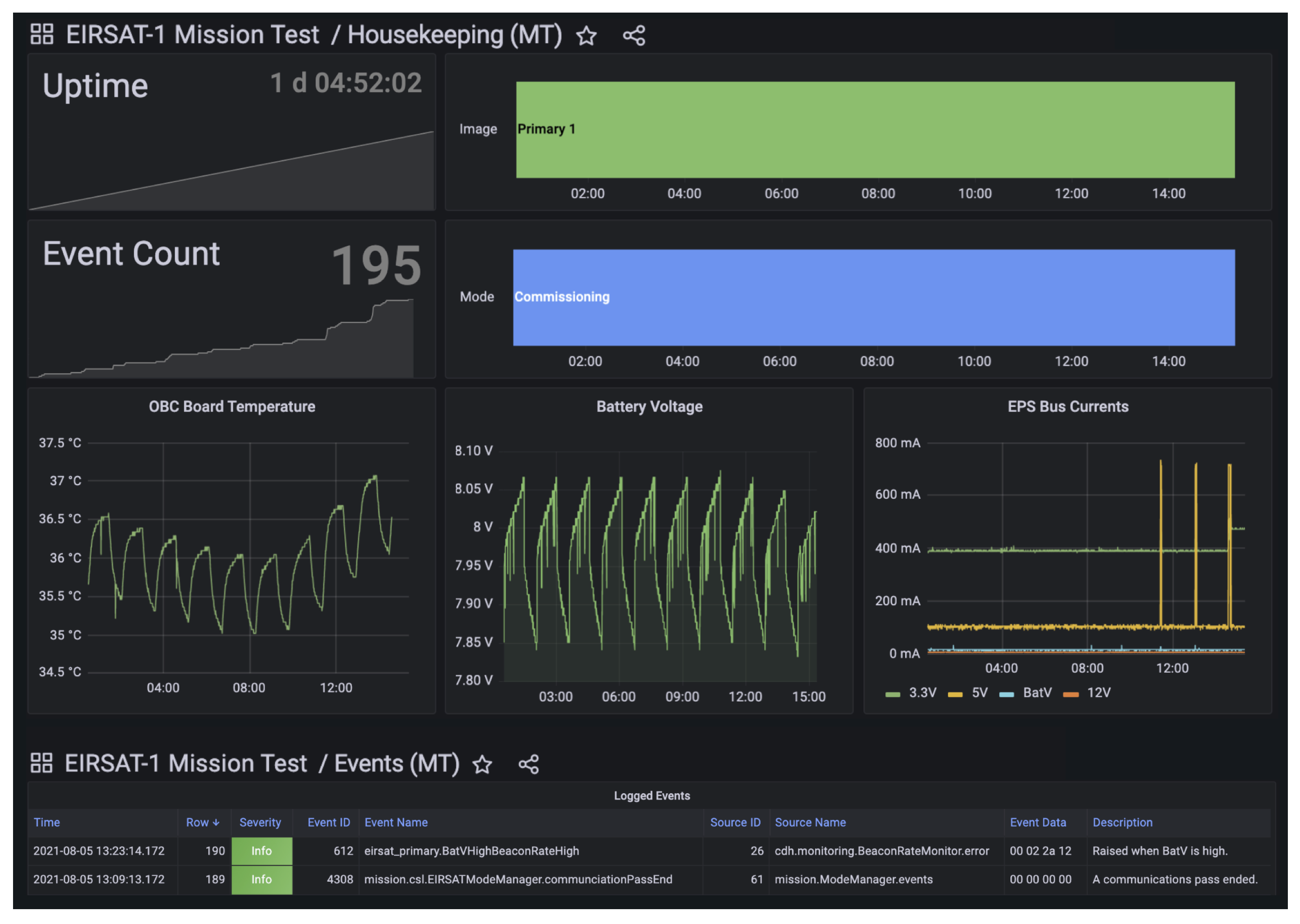
  • Grafana [52]—An open-source, web-based tool for data visualisation. Grafana allows users to construct dashboards, with options to display real-time data, graph historic data and apply conversions. This tool is to be used during the mission test to monitor the health of EIRSAT-1 with automatically populated displays of data downlinked from the spacecraft’s storage channels, as well as real-time data received from the TM beacon. Grafana will also be used for in-flight operations.
  • Earth Simulator—A Python tool developed in house to simulate the effect on battery charging and two-way communications of the spacecraft’s orbit around Earth. The power supply unit (PSU) responsible for charging the batteries is automatically enabled or disabled, as is TM/TC communication with the spacecraft. Earth Simulator uses Skyfield [51] to generate the required times of sunlight, eclipse, pass start and pass end to determine when the appropriate behaviour should occur.

4.6. Test Setup

The mission test must be conducted in an ISO 14644-1 Class 8 clean room [53], which is standard for any EIRSAT-1 testing which involves EQM or FM hardware. Prior to running scenario 1 (i.e., pre-launch preparations), the fully integrated satellite is placed in a vertical support stand on the clean room bench. An umbilical cable connects the spacecraft to the required GSE, including a PSU for battery charging and a Raspberry Pi. The Pi runs Earth Simulator and is, therefore, also connected to the PSU to regulate charging. A laptop running the Mission Control Tool can additionally connect to the Pi via the network to establish TM/TC communication with EIRSAT-1. A further duty of this Pi is to continuously print (live to a terminal) and log debug information output by the OBC over the umbilical via a serial link.
At the end of scenario 1, the spacecraft is moved to a custom-made ‘ADCS rig’, developed to allow the spacecraft to rotate during the mission test at speeds exceeding 30 /s [54] (i.e., the speed at which the spacecraft’s safe mode is triggered). Using slip rings in its design, the same umbilical connections between the spacecraft and GSE can be made in the ADCS rig as above. A polycarbonate sheet is integrated with this rig to support deployed antenna elements. A Python interface is used to control the rate at which the ADCS rig rotates during the test.
Only the test support operators are physically present in the clean room during the mission test, to allow them to monitor the state of the GSE and simulate the spacecraft’s hardware behaviour during certain scenarios. All other operators fulfill their roles virtually using screen sharing software, such as VNC Connect [55], to connect to the laptop which is running the TM/TC GUI. The most up-to-date versions of documentation and tools (described in Section 4.4 and Section 4.5) to be used by the operators during the mission test are available in dedicated folders on the Pi, the TM/TC laptop, and a shared Google Drive, and are maintained by EIRSAT-1’s Operations Team throughout the test.

5. EQM Mission Test

Beginning on 3 August 2021 and lasting 27 days, the mission test plan was executed using the EIRSAT-1 EQM. Before the campaign started, an operator rota was created and agreed on by the 13 available team members. The assignment of roles is summarised as follows:
  • 11 13 were student or early-career (i.e., recently graduated) team members;
  • The Project Manager was assigned as Test Coordinator;
  • Excluding the Project Manager, all other participating team members were allocated the role of spacecraft operator at some point;
  • The role of test support operator was intermittently assigned to 3 of the participating team members (when they were not already assigned as a spacecraft operator);
  • The systems engineer and lead flight software and operations developer were appointed as the on-call operators.
Team members with more experience interacting with the spacecraft were assigned as the LEOP operators, allowing less experienced team members to shadow the early test activities prior to becoming operators themselves.
Prior to commencing the mission test, a test readiness workshop was additionally held by the Operations Team to ensure all team members understood their responsibilities during the test campaign, as well as the documentation and tools they would need to use. Recordings of the workshop were available to team members throughout the mission test.
Table 3 presents EIRSAT-1’s EQM mission test schedule, showing the dates and durations for which each of the scenarios listed in Appendix A were simulated.

5.1. Summary of LEOP Events

A detailed account of the activities during the initial days of testing, covering the LEOP scenarios, is presented in this section to show how the mission test proceeded in practice. Sample data collected are also presented as they provide essential baseline information for in-flight operations. These data are more complete and flight representative than other test data previously collected.
The information provided in this section constitutes a significant part of the formal test report which has been produced to demonstrate to FYS!, ESA and other interested parties (e.g., the launch authorities) that the aims of the mission test, including requirement verification, have been achieved [39].

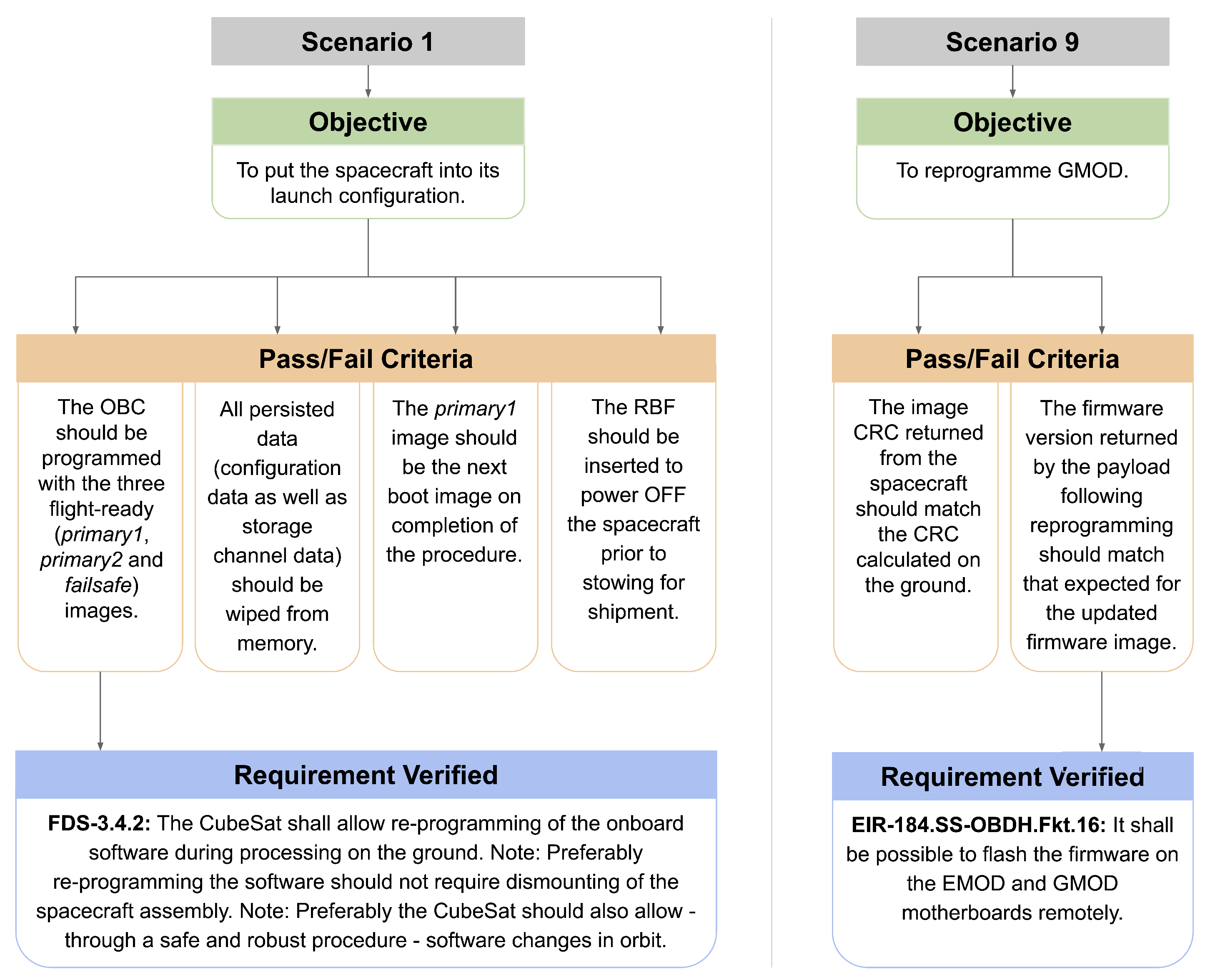
5.1.1. Scenario 1: Pre-Launch Preparations

On 3 August 2021, prior to commencing final pre-launch preparations, the spacecraft was seated in a vertical integration stand with the antenna elements fully coiled, as shown in Figure 7a, all final health checks were performed and the remaining GSE/test setup was put in place.
The test support and spacecraft operators then followed the EIR_OPS procedure ‘EIR-OPS-001: Pre-Launch Preparation’ to prepare the spacecraft to be stowed for launch. As this procedure takes place on the ground, open communication between the test support and spacecraft operators was allowed at this time.
The primary objectives of EIR-OPS-001 are to:
  • Ensure that the correct flight-ready software images are programmed onto the OBC, as well as GMOD and EMOD.
  • Provide an opportunity to uplink mission-specific datasets and downlink data that will be useful to in-flight operations.
  • Ensure that all stored configuration data are erased.
  • Ensure that any old TM logs are erased that might otherwise cause confusion during LEOP.
  • Confirm that the removal of all test inhibit pins (e.g., those used to inhibit radio transmissions during certain test activities) has been detected.
  • Ensure that the desired image boot sequence has been set.
  • Confirm that the satellite is primed to boot into the post-launch separation sequence mode.
These objectives were all achieved on the same day. After the successful execution of this procedure, the remove before flight (RBF) pin was inserted to simulate final power-off prior to stow and launch. From this point on, the spacecraft operators were no longer allowed in the clean room or to access the spacecraft in any way outside of TM/TC communication during passes.
Instructed by the TP, the test support operators then relocated the spacecraft from the vertical integration stand to the ADCS rig, as shown in Figure 7b. When properly housed in this rig, 3D printed ‘switch wedges’ were used to depress the deployment switches at the base of the spacecraft. This was done to better simulate the stowed state of the spacecraft within a CubeSat deployer.

5.1.2. Scenario 2: Launch

On the morning of 4 August 2021, the Earth Simulator software (described in Section 4.5) was configured by the test support operators to control the PSU to simulate a realistic charging cycle for a spacecraft in LEO. Earth Simulator was also configured at this time to block two-way communications between the spacecraft and the spacecraft operators’ Mission Control Tool outside the pre-defined communication pass times. Pass times generated for use by Earth Simulator were intentionally modified to slightly differ from those given in the pass plans, to better reflect the uncertainty of AOS/LOS times during on-orbit operations.
To then “launch” EIRSAT-1, the test support operators first deactivated the RBF pin and removed the switch wedges. They confirmed spacecraft power on at 09:27 UTC (UTC will be the convention used throughout the remainder of this section) using the debug output from the OBC and configured the ADCS rig to rotate at a rate of 5 /s to mimic post-launch tumbling.
Over the next 45 min (a 45 min wait period before activation of deployables is observed to satisfy mission requirements set by FYS!/launch authorities), the test support operators monitored the spacecraft to ensure that the antenna elements remained in their stowed positions, used a hand-held radio to confirm no RF transmission was observed from the spacecraft, and monitored the OBC’s debug output to confirm that all output from the flight software agreed with the observed conditions.
Starting 45 min after launch, deployment of all 4 antenna elements was observed, first with the −Y element, followed by +Y, −X and +X (see Table 4 for accurate timing). A time series of the spacecraft rotating in the ADCS rig following antenna deployment is shown in Figure 7ci→iii. The deployment time of each element was consistent with the OBC’s debug output, which records when the flight software commands a deployment attempt. After all four elements were deployed, RF transmissions consistent with the expected periodicity of the spacecraft’s TM beacon was noted.

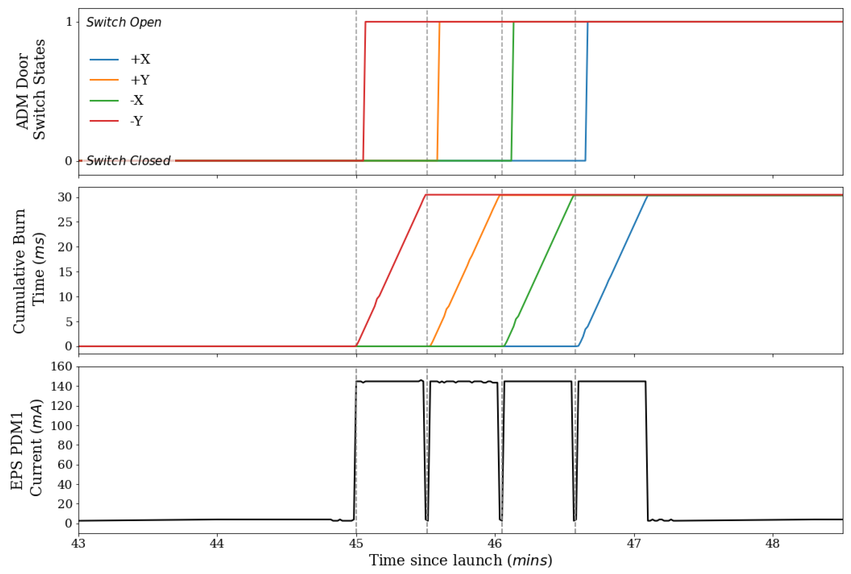
5.1.3. Scenario 3: Initial AOS

Given that all antenna elements were fully deployed and RF transmission was enabled by ∼10:14 on 4 August 2021, the first opportunity for initial AOS was during Pass 20210804.457, a ∼7 min communication window starting at 10:52. As the time of on-orbit deployment was communicated with the full team, the spacecraft operators could use the expected timing of the events in Table 4 to independently determine when the first opportunity for initial AOS should occur. Therefore, during this pass, the spacecraft operators followed the procedure ‘EIR-OPS-004: Initial AOS’, and two-way communication with EIRSAT-1 was established at 10:53:11 with a TM response of 4549525341542d31 in the standard hexadecimal format, or EIRSAT-1 as a string.
As part of EIR-OPS-004, a number of health check parameters are retrieved, including the ADM door switch states parameter (SwitchStatuses), which all read as open (i.e., SwitchStatuses = 0b00001111, where the 4 least significant bits represent the 4 switch states and 1/0 = open/closed). This parameter value was nominally expected, and provided initial verification that all antenna elements were fully deployed. Following this, event and housekeeping data, as well as data related to the ADM, were downlinked from the OBC’s flash storage.
Grafana was used by the spacecraft operators to visualise and check the downlinked data, as shown in Figure 8. All observed parameter values and their behaviour were nominal. For example:
  • uptime, which tracks the cumulative time since an OBC reboot, continually increased since the expected time of power on;
  • batteryVoltage remained within nominal levels (>7.5 V), as the batteries charged and discharged according to the expected on-orbit charging cycle;
  • Events raised by the on-board software indicated that the separation sequence was progressing as intended.
The downlinked ADM data were separately assessed by the ADM engineer. These data (Figure 9) provided further confidence that full antenna deployment had been successfully achieved. More specifically, the times at which the ADM doors sprung open were as expected and deployment times were also consistent with the times at which the EPS passed current through the ADM’s ‘burn resistors’, responsible for releasing the melt-line stowing mechanism [34].
Given these data, the spacecraft operators were instructed to finish the separation sequence and send TCs to transition to commissioning mode during the next pass.

5.1.4. Scenario 4: Commissioning

To carry out post-launch commissioning, the spacecraft operators followed ‘EIR-OPS-006: Commissioning’ which consists of several sub-procedures whose objectives are to:
  • Enable on-board TC authentication checks. This functionality is enabled to prevent replay attacks, but is disabled by default at boot of the OBC to reduce the risk of being ‘locked out’ of the spacecraft.
  • Disable convolution encoding of TM [56]. This encoding is enabled by default to increase the likelihood of establishing a stable TM/TC link with the spacecraft. However, as convolution encoding significantly reduces the data rate, it is disabled when possible.
  • Perform subsystem checkouts to ensure all subsystems survived launch.
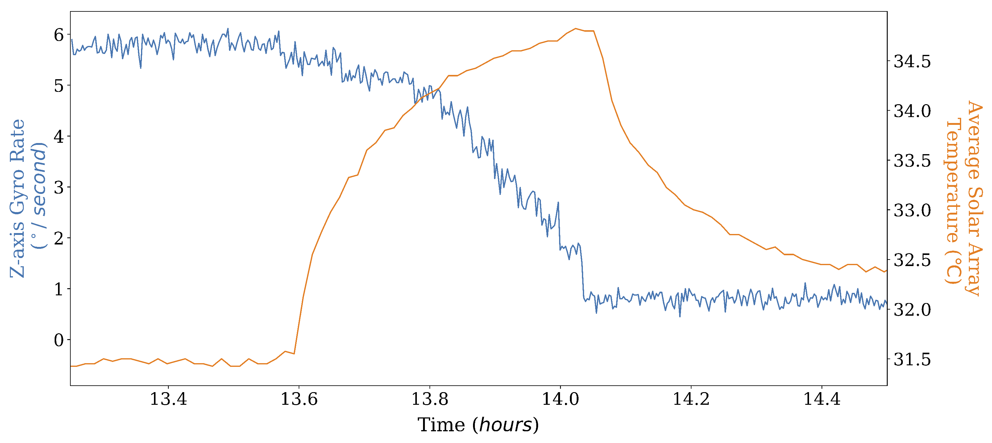
  • De-tumble the spacecraft from its post-launch tumbling.
  • Test basic payload functionality prior to proceeding with full nominal operations.
The full commissioning phase ran from 4 to 13 August 2021, lasting a few days longer than the original schedule estimates. During this time, the test support operators’ main duty was to ensure all GSE continued to perform as expected. When ‘EIR-OPS-006.9: ADCS/GPS Operations’ was reached, the test support operators were also instructed by the TP to control the ADCS rig to spin up/down in response to TCs sent by the spacecraft operators to reduce post-launch tumbling. Verification that the ADCS worked to de-tumble the spacecraft was carried out by the spacecraft operators using the downlinked data, as can be seen in Figure 10.
In addition to the individual subsystem checkouts, the general status of the spacecraft was continually monitored in Grafana by the spacecraft operators using event and housekeeping data which were downlinked at the start of every pass (Figure 8).
During the final days of commissioning, after the health of all critical subsystems had been verified, GMOD and EMOD were commanded to carry out their respective experiments, from which the OBC logged data. Examples of the scientific products, downlinked after a short duration of experiment run time (i.e., between two consecutive pass times) are shown in Figure 11 and Figure 12.
All subsystem checkouts and experiment demonstrations indicated that, having survived launch, the spacecraft was now fit for nominal operations and so the decision was reached to transition to nominal mode.

5.1.5. Scenario 5: First-Time Nominal Mode

During Pass 20210813.430, the spacecraft operators followed ‘EIR-OPS-007: Operational Mode Change’ to perform the transition to nominal mode. During this transition, the payloads are automatically powered on in preparation for experiment operation and the ADCS is configured to continuously stabilise the spacecraft orientation. Instructed by the pass plan, the spacecraft operators followed ‘EIR-OPS-020: GMOD Configuration’ and ‘EIR-OPS-022: EMOD Configuration’ to configure the two experiments. Downlinking of experiment data was nominally planned for the following passes.
This marked the end of the LEOP phase of the mission.

5.2. Key Results

On 30 August 2021, a post-test meeting was held between several of the test operators to review and close-out the EQM mission test activities. This meeting also marked the end of the strict constraints implemented for the test, allowing analyses of all as-run documents to be carried out.
The main conclusions from the close-out review, and key findings from the post-test analyses, can be summarised as follows:
  • I n total, 1921 scenarios were simulated, each lasting from <1 day (e.g., initial AOS) to 10 days (i.e., commissioning).
  • Scenarios 7 (i.e., the GMOD experiment running configuration must be changed) and 17 (an updated OBC image is required) were not simulated. Given the schedule pressure to move on to spacecraft environmental testing, the decision was made to close out the mission test without conducting these 2 scenarios. This was deemed to be low risk as the key functionalities and procedures to be used during these scenarios had been tested successfully during EQM functional tests [45].
  • For the 19 scenarios simulated, all objectives defined in Appendix A were achieved excluding one from scenario 14 (i.e., the CMC’s inactivity beacon has been received by the GS), which was not achieved due to a test anomaly, as described in Section 5.2.1.
  • A total of 41 mission requirements were verified, 5 of which rely solely on mission testing for verification. While 36 of these requirements are also satisfied through other testing methods, the mission test has provided additional confidence that these requirements can be verified in the context of the mission.
  • Nominal operations were established several times. During these times, experiment data were generated, logged and downlinked, meeting EIRSAT-1’s scientific objectives.
  • Several minor anomalies were experienced and worked through over the course of the mission test. For example, on 7 August 2021, the Earth Simulator software tool (Section 4.5) crashed due to an unstable network connection that disrupted communication with the PSU. This was quickly realised by the test support operators and the tool was restarted such that the test was not notably impacted. However, two more significant anomalies were also experienced. These anomalies and their impact on the mission test are discussed in detail in Section 5.2.1.

5.2.1. Anomalies

During the first week of testing, the spacecraft operators noted that the CMC was reaching higher temperatures than expected during passes. To work through this and mitigate risk of hardware damage, the operators paused and resumed downlinks (i.e., excessive transmission) as required to maintain a comfortable CMC temperature. However, after ∼one week, this issue was no longer observed following an unexpected change in the CMC’s current draw. A root cause analysis, involving discussions with the CMC’s manufacturer, points towards damage experienced by this part during earlier ground-based testing and which was subsequently repaired. While this anomaly did not impact the test objectives, an unexpected benefit was that it presented a situation which the operators first needed to catch, and then manage to safely continue the mission. As this damage was only experienced by the EQM CMC, the same anomaly is not expected to occur during FM testing and operations.
During scenario 14 (i.e., the CMC’s inactivity beacon has been received by the GS), the test support operators experienced two major anomalies with respect to the CMC’s inactivity beacon and dual-tone multi-frequency (DTMF) reset capabilities [35]. Firstly, efforts to trigger the CMC’s beacon via blocking I2C communications with the OBC failed. Secondly, DTMF tones sent via a hand-held radio did not invoke an OBC reset. At this late stage of testing, it was decided that the test support operators should take action to mimic what would have been the expected spacecraft behaviour in this scenario to allow the mission test to proceed. Unaware that any issues had been encountered, the spacecraft operators then successfully handled the scenario.
Post-test, an investigation was carried out to assess if the mission would have been lost had the anomaly occurred on orbit. This investigation concretely showed that the anomalies were related to incorrect test support operator instructions, where the TP steps provided were inadequate to fully block OBC-to-CMC I2C transactions, and RF noise in the clean room, respectively. As these findings do not bring into question the performance of the satellite system and as the spacecraft operators managed the scenario appropriately, it was agreed that the mission test should not be failed as a result of these anomalies.

5.3. Lessons Learned

Planning and executing EIRSAT-1’s EQM mission test have proved to be a valuable exercise for the team. The test has shown that the mission objectives can be achieved with the current spacecraft configuration and the planned operational procedures. The strict conditions imposed for the mission test with respect to limited two-way communication and pass durations, has built confidence that the satellite can survive without operator interaction for prolonged periods of time, even in the event of an anomaly. As there is currently only one EIRSAT-1 GS, this is a significant outcome that could only be fully verified prior to launch through the mission test.
The successful execution of the mission test also demonstrates that the methods, tools and documentation put in place to manage the mission are sufficient to fulfil their intended purpose.
Additional lessons learned include
  • Mission testing is a useful method of operator training—Although other approaches taken in the past to build knowledge about spacecraft operations within the team were crucial to developing plans, documentation and tools for operations, they could not provide the same operator experience as long-duration, flight-representative mission testing. These aspects of the mission test uniquely built familiarity with the necessary tools/documentation for EIRSAT-1 operations and confidence in operating the mission. Therefore, newer, as well as more experienced, team members should be actively involved in mission testing as a proven means of hands-of operator training. In particular for newer team members, the opportunity to shadow more experienced operators during LEOP activities also proved to be a highly beneficial learning experience.
  • The role of subsystem engineer should be defined within the mission test plan—Section 4.3 does not include roles for team members who are responsible for the spacecraft’s subsystems. While in many cases the on-call operators were able to support queries, additional input from the subsystem engineers (when they were not already on-duty as a spacecraft operator) was required during the test, particularly during commissioning.
  • Detailed as-run test records are crucial—While the mission test generated hundreds of pages worth of as-run documentation and data, the level of detail recorded during the ∼month of testing was essential to post-test analyses and writing of test reports which was only done after the mission test close-out, up to a couple of weeks after the test. Therefore, the importance of promptly capturing as-run details should be emphasised to all team members responsible for maintaining these records.
  • Treating unplanned anomalies as part of the mission test is valuable—More specifically, this refers to off-nominal events that were not intentionally injected into the test (see Section 5.2.1 for examples). Although time consuming and disruptive to the planned test activities, when confronted by unanticipated scenarios and anomalies, operators had to improvise with available tools and knowledge to regain control of the mission and return to nominal operations. This process highlighted previously overlooked gaps and flaws in the EIR_OPS procedures and flight software implementation that can be corrected and improved upon. The anomalies encountered also allowed the team to develop a better understanding of the potential fault behaviours in a way that otherwise may not have been observed prior to launch.
  • Automated mission control methods are essential for long-term operations—No automated TM/TC mission control tools were available for use during the EQM mission test. Although implementing procedures manually was a valuable learning exercise, the lack of automated mission control methods exhausted the operators over the ∼month of testing where, even during nominal operations, their full attention and hands-on participation were required. The time between passes was fully occupied with analysis, troubleshooting and documentation, which would not be sustainable long-term for the mission. The mission test has therefore brought the need for automated mission control tools to the forefront.

6. Future Developments

Two weeks after the mission test concluded, environmental testing was carried out on the EQM at ESA’s CubeSat Support Facility based in Redu, Belgium, and included vibration and TVAC tests. This was the last major test campaign planned for the EQM of EIRSAT-1.
Given some minor hardware differences between the EQM and FM (e.g., the EQM’s solar panels are fitted with dummy solar cells [21]) as well as essential updates to the flight and GS software, repeating test campaigns, such as the mission test with the FM is considered important for requirement verification and mission validation.
The following lists some key improvements intended to be made to the FM mission test plan, building on lessons learned from the EQM test experience and incorporating elements not available at the time of the EQM mission test:
  • GS hardware/software—Some elements of the GS were not ready for the EQM mission test and so the role of EIRSAT-1’s GS chain is not fully defined in the test plan. As the mission test aims to validate that the full system can perform the intended mission, not just the satellite system, this will be improved for future testing.
  • Operators—As discussed in Section 5.3, the role of subsystem engineers will be incorporated.
  • Communication—Clearer lines of communication in the event of a test anomaly will also be considered. While these were well-defined for the spacecraft operators, when other test operators, with more exclusive knowledge about the state of the spacecraft, experienced an anomaly, there was uncertainty over who could be contacted without breaking the constraints of the mission test. To overcome this issue, ideally, the team member primarily responsible for the mission test should not be assigned as a spacecraft operator so that they can act as a point of contact for all operators during the test.
  • Scenarios—Scenarios 1–5 of the EQM mission test simulated a nominal LEOP, where no potential failure events were considered. For the FM test campaign, a number of ∼days-long mission tests should be performed that consider worst-case launch conditions (e.g., low battery levels at launch, long wait times to initial AOS, and repeating OBC reboots during the separation sequence).
    Post-LEOP scenarios related to WBC, EIRSAT-1’s software-based attitude control payload, which was not sufficiently mature at the time of the EQM mission test, will also be added to the FM test plan.
  • As-run test documentation—Post-test analyses for the EQM mission test relied heavily on the as-run documentation. As a result, the format of this documentation will be reviewed and streamlined where possible to ensure the quality of future as-run records. For example, the pass plan document discussed in Section 4.4.3 largely served its intended purpose. However, an absence of requirements about the content and detail of notes to be recorded by the spacecraft operators led to inconsistency in the quality of the records. Future versions of the pass plans will include a template that prompts the operators for (at a minimum) specific details on the pass events.
Further updates to the mission test plan, towards ever more mission representative tests, are possible. For instance, the test could be run over longer durations, battery charging could be carried out via the spacecraft’s solar cells using a sun simulator, or more realistic elements of the space environment (e.g., with respect to temperature, pressure and radiation) could be incorporated. However, the resources required to plan and implement the mission test can eventually outweigh the benefits returned. The point at which this occurs can only be decided upon by each CubeSat team. As an example, for EIRSAT-1, on-orbit environmental conditions have not been included as part of mission testing given the scale of resources this would require to implement. Instead, the custom payloads as well as the fully integrated EQM have separately been through extensive functional and environmental testing [21,24,25], while all of the COTS components have flight heritage [35].

7. Conclusions

Reviews of lessons learned by CubeSat teams with on-orbit experience highlight mission representative testing as a key method to improve the likelihood of mission success [15,57]. Even still, studies find that a standard approach to good quality mission testing is not widely adopted by CubeSat projects [17]. This can largely be attributed to the significant challenge to resources which quality mission testing presents. It may also be related to a lack of detailed information in the literature on effective mission testing efforts taken by CubeSat teams. To address both issues, this work presents EIRSAT-1’s mission test plan, which required a significant investment of the project’s time and resources to develop. This investment was considered worthwhile for EIRSAT-1, not only to meet the FYS! Programme requirement to conduct some level of mission testing, but also because of the considerable benefit to the team that extends beyond requirement verification to include
  • Validation of the on-orbit performance of the system;
  • Promotion of flight readiness well before launch;
  • Production of a baseline for the spacecraft behaviour and data generated on orbit.
The effectiveness of the test plan presented in this work is supported by EIRSAT-1’s successful EQM mission test campaign.

Author Contributions

Conceptualization, all authors; methodology, M.D., R.D., G.F., D.M. (David Murphy), J.R., J.T., S.W., L.H. (Lily Ha) and D.P.; software, M.D., D.M. (David Murphy), J.R., J.T., J.M. and A.U.; validation, M.D., R.D., G.F., D.M. (David Murphy), J.R., J.T., J.M., S.W., F.M. and L.S.; formal analysis, M.D.; investigation, M.D., R.D., G.F., D.M. (David Murphy), J.R., J.T., S.K.R.A., J.M., S.W., R.W. and L.H. (Lorraine Hanlon); resources, D.M. (David Murphy), J.R. and J.T.; data curation, M.D., R.D., G.F., D.M. (David Murphy), J.R. and J.T.; visualisation, M.D.; writing—original draft preparation, M.D.; writing—review and editing, all authors; Supervision, A.M.-C. and L.H. (Lorraine Hanlon); project administration, R.W.; funding acquisition, A.M.-C., S.M., D.M. (David McKeown), W.O., R.W. and L.H. (Lorraine Hanlon). All authors have read and agreed to the published version of the manuscript.

Funding

M.D., R.D., D.Mu., L.S. and J.T. acknowledge support from the Irish Research Council under grants GOIPG/2018/2564, GOIPG/2019/2033, GOIPG/2014/453, GOIPG/2017/1525 and GOIPG/2014/684, respectively. G.F. acknowledges support from a scholarship associated with the UCD Ad Astra fellowship programme. D.Mu., A.U., J.M. and S.M. acknowledge support from Science Foundation Ireland (SFI) under grant 17/CDA/4723. S.W. acknowledges support from ESA under PRODEX contract number 400012071. J.E. and J.R. acknowledge scholarships from the UCD School of Physics. F.M. acknowledges support from the UCD School of Computer Science. Lo.H. acknowledges support from SFI under grant 19/FFP/6777 and support from EU H2020 AHEAD2020 project (grant agreement 871158). This study was supported by ESA’s Science Programme under contract 4000104771/11/NL/CBi and by ESA’s PRODEX Programme under contract number C 4000124425.

Institutional Review Board Statement

Not applicable.

Informed Consent Statement

Not applicable.

Data Availability Statement

Data sharing is not applicable to this article.

Acknowledgments

The EIRSAT-1 project is supported by ESA’s Education Office, under the 2nd round of the FYS! Programme. The authors further acknowledge guidance from Aldous Mills, formerly a Young Graduate Trainee with FYS!, and Jean-Philippe Halain of the ESA PRODEX Office. The project acknowledges all students who have contributed to EIRSAT-1 and support from Parameter Space Ltd.

Conflicts of Interest

The authors declare no conflict of interest.

Appendix A

Table A1. EIRSAT-1’s mission test scenarios, where S/C = spacecraft, RF = radio frequency, AOS = acquisition of signal, GS = ground segment, P/L = payload and FDIR = fault detection, isolation and recovery, and ITU = International Telecommunications Union. Scenarios that could in reality be invoked under either nominal or off-nominal circumstances. For instance, a software update could be required under off-nominal circumstances, due to a fault, or nominally, as an upgrade. The ‘type’ assigned here refers to the circumstances under which the scenario is to be invoked during EIRSAT-1’s mission test.
#TypeDescriptionObjective(s)
1Nom.The S/C is prepared for launch at next boot as this is the last time EIRSAT-1 will be powered ON on the ground prior to launch.
  • To put the S/C into its launch configuration.
2Nom.The S/C is deployed into orbit and powers ON. After ≥45 min, the separation sequence begins antenna deployment attempts, deploys the antenna and then enables RF transmission.
  • To deploy the S/C’s antennas.
  • To begin RF transmission.
3Nom.After ∼1–2 h of waiting for a communication window with the S/C, the GS communicates with EIRSAT-1 for the first time on orbit (initial AOS!). An initial assessment of the S/C’s health following launch is performed and antenna deployment is confirmed via downlinked data.
  • To establish two-way comms.
  • To confirm antenna deployment.
  • To determine the current operational state of the S/C.
4Nom.Commissioning of the S/C is performed to assess the health of the system following launch. Detumbling of the S/C will also be performed following ADCS health checks.
  • To confirm that the S/C’s subsystems are fully functional following launch.
5Nom.Nominal mode is entered for the first time. Nominal operations (i.e., prolonged experiment running and data collection) begin.
  • To exit commissioning mode and begin nominal mode/operations.
6Nom.No specific procedure is planned or on-going. Therefore, during the upcoming pass, data downlink from on-board storage is carried out.
  • To downlink data from the on-board storage channels.
7Nom.A change to the configuration of the GMOD experiment is required. The configuration update is performed and fully confirmed with TM from the P/L.
  • To re-configure the GMOD experiment.
8Nom.A change to the configuration of the EMOD experiment is required. The configuration update is performed and fully confirmed with TM from the P/L.
  • To re-configure the EMOD experiment.
9Nom.  A firmware update of the GMOD P/L is required. The new image is uplinked to the OBC and the P/L is reprogrammed.
  • To reprogramme GMOD.
10Off-Nom.The S/C is operating in safe mode due to a full S/C power cycle. This anomaly is investigated by the team, the most likely root cause is identified and a solution to return to nominal operations is implemented.
  • To determine the most likely scenario that led to the mode entry.
  • To exit safe mode and resume nominal operations.
11Off-Nom.The beacon data suggest that the S/C is operating nominally; however, no responses are being received to any TCs. This anomaly is investigated by the team, the most likely root cause is identified, and a solution to return to nominal operations is implemented.
  • To re-establish two-way communications with the S/C.
12Nom.The GMOD on-board storage channels are (almost) full and so, if the data have already been downlinked, at least some of these channels should be wiped.
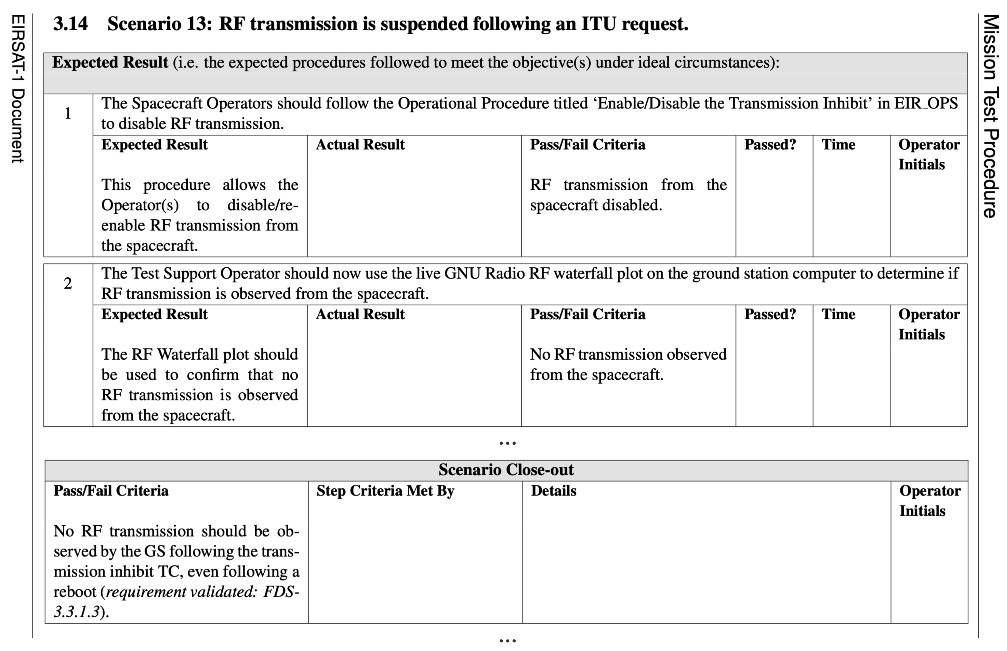
  • To clear the data currently occupying the GMOD storage channels.
13Off-Nom.A temporary suspension of all RF transmission from the S/C is requested by the ITU. Therefore, RF transmission is ceased and then later re-enabled via TCs to the S/C. Later downlink of TM indicates that a full S/C power cycle also occurred while the RF transmission inhibit was still enabled.
  • To disable RF transmission for the requested duration.
  • To re-enable RF transmission after the requested duration.
  • To resume nominal operations.
14Off-Nom.The CMC’s inactivity beacon has been received by the GS and other communication with the S/C has not been possible. This anomaly is investigated by the team, the most likely root cause is identified, and a solution to return to nominal operations is implemented.
  • To perform an OBC reset using the DTMF tones.
  • To re-establish full two-way communications with the S/C.
  • To exit safe mode and resume nominal operations.
15Off-Nom.The S/C is operating in safe mode due to the low battery voltage FDIR check being triggered. This anomaly is investigated by the team, the most likely root cause is identified, and a solution to return to nominal operations is implemented.
  • To determine the most likely scenario that led to the mode entry.
  • To exit safe mode and resume nominal operations.
16Off-Nom.The S/C is operating in the failsafe image due to 2 or more reboots occurring within 2 h of each other. This anomaly is investigated by the team, the most likely root cause is identified and a solution to return to nominal operations is implemented.
  • To promptly identify the current operational image/mode/state of the S/C.
  • To determine the most likely scenario that led to the changed current boot image.
  • To resume nominal operations.
17Nom.  An updated flight software image is required. The image is uplinked, booted and verified as stable.
  • To uplink an updated flight software image to the S/C.
  • To boot and verify the new image.
18Nom.  A change to the automatic FDIR checks on-board is desired where the upper limit of the monitored total gyro rate parameter must be changed from 30  /s to 10  /s.
  • To re-configure the on-board FDIR checks.
19Off-Nom.The S/C is operating in safe mode due to the high gyro rate FDIR check being triggered. This anomaly is investigated by the team, the most likely root cause is identified and a solution to return to nominal operations is implemented.
  • To determine the most likely scenario that led to the safe mode transition.
  • To exit safe mode and resume nominal operations.
20Nom.  A change to the automatic FDIR checks on-board is desired where the no-TC watchdog timeout must be changed to a duration of 1 day.
  • To re-configure the on-board FDIR checks.
21Off-Nom.The S/C is operating in separation sequence mode, even though this mode has previously been exited and so should not have been re-entered under nominal conditions. This anomaly is investigated by the team, the most likely root cause is identified and a solution to return to nominal operations is implemented.
  • To determine the most likely scenario that led to the repeated first-boot scenario.
  • To exit separation sequence mode and resume nominal operations.

References and Note

  1. CubeSat Database. Available online: https://sites.google.com/a/slu.edu/swartwout/cubesat-database (accessed on 21 November 2021).
  2. California Polytechnic State University (Cal Poly). CubeSat Design Specification (CDS) Rev 13; CP-CDS-R13; Cal Poly: San Luis Obispo, CA, USA, 2014. [Google Scholar]
  3. Villela, T.; Costa, C.; Brandão, A.; Bueno, F.; Leonardi, R. Towards the Thousandth CubeSat: A Statistical Overview. Int. J. Aerosp. Eng. 2019, 2019, 5063145. [Google Scholar] [CrossRef]
  4. Nanosats Database. Available online: https://www.nanosats.eu/ (accessed on 21 November 2021).
  5. Heidt, H.; Puig-Suari, J.; Moore, A.S.; Nakasuka, S.; Twiggs, R.J. CubeSat: A new Generation of Picosatellite for Education and Industry Low-Cost Space Experimentation. In Proceedings of the 14th Annual AIAA/USU Conference on Small Satellites, SSC00-V-5, Logan, UT, USA, 21–24 August 2000. [Google Scholar]
  6. Kroeker, E.; Ghosh, A.R.M.; Coverstone, V.L. Building Engineers: A 15-Year Case Study in CubeSat Education. In Proceedings of the 30th Annual AIAA/USU Conference on Small Satellites, SSC16-XIII-07, Logan, UT, USA, 6–11 August 2016. [Google Scholar]
  7. Murphy, D.; Lynn, D.; McBreen, S.; Martin-Carrillo, A.; Coffey, D.; Jeffrey, R.; Vagg, D.; Hanlon, L. EduCube—The 1U Educational CubeSat. In Proceedings of the 2nd Symposium on Space Educational Activities (SSEA), SSEA-2018-67, Budapest, Hungary, 11–13 April 2018. [Google Scholar]
  8. Agasaid, E.; Hunter, R.; Baker, C.; Marmie, J.; Foreman, D. NASA’s Pathfinder Technology Demonstrator. In Proceedings of the 31st Annual AIAA/USU Conference on Small Satellites, SSC17-III-2, Logan, UT, USA, 5–10 August 2017. [Google Scholar]
  9. Mughal, M.R.; Praks, J.; Vainio, R.; Janhunen, P.; Envall, J.; Näsilä, A.; Oleynik, P.; Niemelä, P.; Nyman, S.; Slavinskis, A.; et al. Aalto-1, multi-payload CubeSat: In-orbit results and lessons learned. Acta Astronaut. 2021, 187, 557–568. [Google Scholar] [CrossRef]
  10. Schoolcraft, J.; Klesh, A.T.; Werne, T. MarCO: Interplanetary Mission Development On a CubeSat Scale. In Proceedings of the 2016 SpaceOps Conference, AIAA 2016-2491, Daejeon, Korea, 16–20 May 2016. [Google Scholar] [CrossRef]
  11. Pál, A.; Ohno, M.; Mészáros, L.; Werner, N.; Ripa, J.; Frajt, M.; Hirade, N.; Hudec, J.; Kapuš, J.; Koleda, M.; et al. GRBAlpha: A 1U CubeSat mission for validating timing-based gamma-ray burst localization. In Proceedings of the Space Telescopes and Instrumentation 2020: Ultraviolet to Gamma Ray, International Society for Optics and Photonics; SPIE: Washington, DC, USA, 2020; Volume 11444, pp. 825–833. [Google Scholar] [CrossRef]
  12. David, L.; Lacour, S.; Lapeyrere, V.; Crouzier, A.; Nowak, M. PicSat: A CubeSat for beta Pictoris observation. In Proceedings of the 42nd COSPAR Scientific Assembly, Pasadena, CA, USA, 14–22 July 2018; Volume 42, p. E4.1-22-18. [Google Scholar]
  13. Moore, C.S.; Caspi, A.; Woods, T.N.; Chamberlin, P.C.; Dennis, B.R.; Jones, A.R.; Mason, J.P.; Schwartz, R.A.; Tolbert, A.K. The Instruments and Capabilities of the Miniature X-Ray Solar Spectrometer (MinXSS) CubeSats. Sol. Phys. 2018, 293, 1–40. [Google Scholar] [CrossRef] [PubMed] [Green Version]
  14. Swartwout, M. The First One Hundred CubeSats: A Statistical Look. J. Small Satell. 2013, 2, 213–233. [Google Scholar]
  15. Venturini, C.; Braun, B.; Hinkley, D. Improving Mission Success of CubeSats. In Proceedings of the 32nd Annual AIAA/USU Conference on Small Satellites, SSC18-IV-02, Logan, UT, USA, 4–9 August 2018. [Google Scholar]
  16. Langer, M.; Bouwmeester, J. Reliability of CubeSats—Statistical Data, Developers’ Beliefs and the Way Forward. In Proceedings of the 30th Annual AIAA/USU Conference on Small Satellites, SSC16-X-2, Logan, UT, USA, 6–11 August 2016. [Google Scholar]
  17. Doyle, M.; Dunwoody, R.; Finneran, G.; Murphy, D.; Reilly, J.; Thompson, J.; Walsh, S.; Erkal, J.; Fontanesi, G.; Mangan, J.; et al. Mission testing for improved reliability of CubeSats. In Proceedings of the 2020 International Conference on Space Optics (ICSO), Virtual, 30 March–2 April 2021. [Google Scholar] [CrossRef]
  18. Langer, M.; Weisgerber, M.; Bouwmeester, J.; Hoehn, A. A reliability estimation tool for reducing infant mortality in Cubesat missions. In Proceedings of the 2017 IEEE Aerospace Conference, Big Sky, MT, USA, 4–11 March 2017; pp. 1–9. [Google Scholar] [CrossRef] [Green Version]
  19. Woellert, K.; Ehrenfreund, P.; Ricco, A.J.; Hertzfeld, H. Cubesats: Cost-effective science and technology platforms for emerging and developing nations. Adv. Space Res. 2011, 47, 663–684. [Google Scholar] [CrossRef]
  20. Richardson, G.; Schmitt, D.K.; Covert, M.A.; Rogers, C. Small Satellite Trends 2009–2013. In Proceedings of the 29th Annual AIAA/USU Conference on Small Satellites, SSC15-VII-3, Logan, UT, USA, 8–13 August 2015. [Google Scholar]
  21. Walsh, S.; Murphy, D.; Doyle, M.; Thompson, J.; Dunwoody, R.; Emam, M.; Erkal, J.; Flanagan, J.; Fontanesi, G.; Gloster, A.; et al. Assembly, Integration, and Verification Activities for a 2U CubeSat, EIRSAT-1. In Proceedings of the 3rd Symposium on Space Educational Activities (SSEA), Leicester, UK, 16–18 September 2019. [Google Scholar] [CrossRef]
  22. Monteiro, J.P.; Rocha, R.M.; Silva, A.; Afonso, R.; Ramos, N. Integration and Verification Approach of ISTSat-1 CubeSat. Aerospace 2019, 6, 131. [Google Scholar] [CrossRef] [Green Version]
  23. Praks, J.; Mughal, M.R.; Vainio, R.; Janhunen, P.; Envall, J.; Oleynik, P.; Näsilä, A.; Leppinen, H.; Niemelä, P.; Slavinskis, A.; et al. Aalto-1, multi-payload CubeSat: Design, integration and launch. Acta Astronaut. 2021, 187, 370–383. [Google Scholar] [CrossRef]
  24. Mangan, J.; Murphy, D.; Dunwoody, R.; Ulyanov, A.; Thompson, J.; Javaid, U.; O’Toole, C.; Doyle, M.; Emam, M.; Erkal, J.; et al. The environmental test campaign of GMOD: A novel gamma-ray detector. In Proceedings of the International Conference on Space Optics—ICSO 2020; Cugny, B., Sodnik, Z., Karafolas, N., Eds.; SPIE: Washington, DC, USA, 2021; Volume 11852, pp. 471–491. [Google Scholar] [CrossRef]
  25. Ulyanov, A.; Murphy, D.; Mangan, J.; Gupta, V.; Hajdas, W.; de Faoite, D.; Shortt, B.; Hanlon, L.; McBreen, S. Radiation damage study of SensL J-series silicon photomultipliers using 101.4 MeV protons. Nucl. Instrum. Methods Phys. Res. Sect. A Accel. Spectrom. Detect. Assoc. Equip. 2020, 976, 164203. [Google Scholar] [CrossRef]
  26. Murphy, D.; Flanagan, J.; Thompson, J.; Doyle, M.; Erkal, J.; Gloster, A.; O’Toole, C.; Salmon, L.; Sherwin, D.; Walsh, S.; et al. EIRSAT-1—The Educational Irish Research Satellite. In Proceedings of the 2nd Symposium on Space Educational Activities (SSEA), SSEA-2018-73, Budapest, Hungary, 11–13 April 2018. [Google Scholar]
  27. Vanreusel, J. Fly Your Satellite! The ESA Academy CubeSats programme. In Proceedings of the ITU Symposium & Workshop on Small Satellite Regulation and Communication Systems, Santiago de Chile, Chile, 7–9 November 2016. [Google Scholar]
  28. Doherty, K.; Twomey, B.; McGlynn, S.; MacAuliffe, N.; Norman, A.; Bras, B.; Olivier, P.; McCaul, T.; Stanton, K. High-Temperature Solar Reflector Coating for the Solar Orbiter. J. Spacecr. Rocket. 2016, 53, 1–8. [Google Scholar] [CrossRef]
  29. Doherty, K.A.J.; Dunne, C.F.; Norman, A.; McCaul, T.; Twomey, B.; Stanton, K.T. Flat Absorber Coating for Spacecraft Thermal Control Applications. J. Spacecr. Rocket. 2016, 53, 1035–1042. [Google Scholar] [CrossRef]
  30. Sherwin, D.; Thompson, J.; McKeown, D.; O’Connor, W.; Úbeda, V. Wave-based attitude control of EIRSAT-1, a 2U CubeSat. In Proceedings of the 2nd Symposium on Space Educational Activities, SSEA-2018-93, Budapest, Hungary, 11–13 April 2018. [Google Scholar]
  31. Murphy, D.; Ulyanov, A.; McBreen, S.; Doyle, M.; Dunwoody, R.; Mangan, J.; Thompson, J.; Shortt, B.; Martin-Carrillo, A.; Hanlon, L. A compact instrument for gamma-ray burst detection on a CubeSat platform I: Design drivers and expected performance. Exp. Astron. 2021, 52, 59–84. [Google Scholar] [CrossRef] [PubMed]
  32. Murphy, D. A compact instrument for gamma-ray burst detection on a CubeSat platform II: Detailed design, assembly and validation. Exp. Astron. 2021; submitted. [Google Scholar]
  33. Mészáros, P. Gamma-ray bursts. Rep. Prog. Phys. 2006, 69, 2259–2321. [Google Scholar] [CrossRef]
  34. Thompson, J.; Murphy, D.; Erkal, J.; Flanagan, J.; Doyle, M.; Gloster, A.; O’Toole, C.; Salmon, L.; Sherwin, D.; Walsh, S.; et al. Double-dipole antenna deployment system for EIRSAT-1, a 2U CubeSat. In Proceedings of the 2nd Symposium on Space Educational Activities (SSEA), SSEA-2018-78, Budapest, Hungary, 11–13 April 2018. [Google Scholar]
  35. Clyde Space Ltd. (CSL) and Cape Peninsula University of Technology (CPUT), COTS Hardware Reference Documents. (ADCS) CSL ICD-25- 01232 Rev. F, 2017; (Battery) CSL USM-1192 Issue C, 2016; (CMC) CPUT ICD-01-00045 Rev. B, 2017; (EPS) CSL USM-1335 Rev. A, 2016; (OBC) CSL ICD-25-025555 Rev. A, 2016; (Solar Array Side Panel) CSL ICD-25-02871 Rev. A 2017; (Structure) CSL ICD-00-04499 Rev. E, 2018; CSL: Glasgow, UK; CPUT: Cape Town, South Africa.
  36. Doyle, M.; Gloster, A.; O’Toole, C.; Mangan, J.; Murphy, D.; Dunwoody, R.; Emam, M.; Erkal, J.; Flanaghan, J.; Fontanesi, G.; et al. Flight Software Development for the EIRSAT-1 mission. In Proceedings of the 3rd Symposium on Space Educational Activities (SSEA), Leicester, UK, 16–18 September 2019. [Google Scholar] [CrossRef]
  37. Mangan, J.; Murphy, D.; Dunwoody, R.; Doyle, M.; Ulyanov, A.; Hanlon, L.; Shortt, B.; McBreen, S.; Emam, M.; Erkal, J.; et al. Embedded Firmware Development for a Novel CubeSat Gamma-Ray Detector. In Proceedings of the 8th IEEE International Conference on Space Mission Challenges, online, 26–30 July 2021. [Google Scholar]
  38. European Cooperation For Space Standardisation (ECSS). Space Engineering: Testing, ECSS-E-ST-10-03C; ECSS: Noordwijk, The Netherlands, 2012. [Google Scholar]
  39. National Aeronautics and Space Administration (NASA) CubeSat Launch Initiative. CubeSat 101: Basic Concepts and Processes for First-Time CubeSat Developers, 1st ed.; NASA: Washington, DC, USA, 2017.
  40. European Space Agency (ESA). Tailored ECSS Engineering Standards for In-Orbit Demonstration CubeSat Projects, TEC-SY/128/2013/SPD/RW; ESA-ESTEC: Noordwijk, The Netherlands, 2016. [Google Scholar]
  41. Jain, V.; Bindra, U.; Murugathasan, L.; Newland, F.; Zhu, Z.H. Practical Implementation of Test-As-You-Fly for the DESCENT CubeSat Mission. In Proceedings of the 2018 SpaceOps Conference, AIAA 2018-2691, Marseille, France, 28 May–1 June 2018. [Google Scholar] [CrossRef]
  42. Gebara, C.A.; Spencer, D. Verification and Validation Methods for the Prox-1 Mission. In Proceedings of the 30th Annual AIAA/USU Conference on Small Satellites, SSC16-VIII-3, Logan, UT, USA, 6–11 August 2016. [Google Scholar]
  43. Macedo, P.L.G. Debris Mitigation, Assembly, Integration, and Test, in the Context of the ISTsat-1 Project. Master’s Thesis, Instituto Superior Técnico, Lisbon, Portugal, 2018. [Google Scholar]
  44. Koudelka, O.; Bichinho Whittle Coelho, C.; Evans, D. The OPS-SAT Nanosatellite Mission. In Proceedings of the IAA Small Satellite Symposium, Berlin, Germany, 24–28 April 2017. [Google Scholar]
  45. Walsh, S.; Murphy, D.; Doyle, M.; Reilly, J.; Thompson, J.; Dunwoody, R.; Erkal, J.; Finneran, G.; Fontanesi, G.; Mangan, J.; et al. Development of the EIRSAT-1 CubeSat through Functional Verification of the Engineering Qualification Model. Aerospace 2021, 8, 254. [Google Scholar] [CrossRef]
  46. Marshall, F.; Murphy, D.; Salmon, L.; O’Callaghan, D.; Doyle, M.; Reilly, J.; Dunwoody, R.; Erkal, J.; Finneran, G.; Fontanesi, G.; et al. Development of the Ground Segment Communication System for the EIRSAT-1 CubeSat. In Proceedings of the 16th International Conference on Space Operations, Virtual, 3–5 May 2021. [Google Scholar]
  47. Dunwoody, R.; Doyle, M.; Murphy, D.; Finneran, G.; O’Callaghan, D.; Reilly, J.; Thompson, J.W.; Walsh, S.; Erkal, J.; Fontanesi, G.; et al. Development and Validation of the Operations Procedures and Manual for a 2U CubeSat, EIRSAT-1, with Three Novel Payloads. In Proceedings of the 16th International Conference on Space Operations, Virtual, 3–5 May 2021. [Google Scholar]
  48. Sphinx. Available online: www.sphinx-doc.org (accessed on 21 November 2021).
  49. Google Calendar API Guide. Available online: https://developers.google.com/calendar/api/quickstart/python (accessed on 21 November 2021).
  50. Google Docs API Guide. Available online: https://developers.google.com/docs/api/quickstart/python (accessed on 21 November 2021).
  51. Skyfield. Available online: https://rhodesmill.org/skyfield/ (accessed on 21 November 2021).
  52. Grafana. Available online: https://grafana.com/ (accessed on 21 November 2021).
  53. International Organization for Standardization (ISO). Cleanrooms and Associated Controlled Environments—Part 1: Classification of air Cleanliness by Particle Concentration, ISO 14644-1:2015(en); ISO: Geneva, Switzerland, 2015. [Google Scholar]
  54. Dunwoody, R.; Thompson, J.; Sherwin, D.; Doyle, M.; Emam, M.; Erkal, J.; Flanagan, J.; Fontanesi, G.; Gloster, A.; Mangan, J.; et al. Design and development of a 1-axis attitude control testbed for functional testing of EIRSAT-1. In Proceedings of the 3rd Symposium on Space Educational Activities (SSEA), Leicester, UK, 16–18 September 2019. [Google Scholar] [CrossRef]
  55. VNC Connect. Available online: https://www.realvnc.com/en/ (accessed on 21 November 2021).
  56. Consultative Committee for Space Data Systems (CCSDS). TM Synchronization and Channel Coding, CCSDS 131.0-B-3; ESA-ESTEC: Noordwijk, The Netherlands, 2020. [Google Scholar]
  57. Final Report Summary—QB50 (An International Network of 50 CubeSats for Multi-Point, In-Situ Measurements in the Lower Thermosphere and Re-Entry Research). Available online: https://cordis.europa.eu/project/id/284427/reporting (accessed on 24 November 2021).
Figure 1. Fully integrated engineering qualification model (EQM) of EIRSAT-1, showing the satellite’s constituent components in the stacked configuration. The main structural parts, solar panels, attitude determination and control system (ADCS), on-board computer (OBC), electrical power system (EPS), battery and communications component (CMC) are from AAC Clyde Space. All elements of the EMOD and GMOD payloads, as well as the antenna deployment module (ADM), are custom built in house. To reduce costs, the EQM is fitted with mass-representative mock-ups of solar panels with real cells.
Aerospace 09 00100 g001
Figure 2. Block diagram of the mission test organisation presented in this work, where GSE = ground support equipment and TM/TC = telemetry/telecommands. The remaining terms are introduced in the text of Section 4.
Aerospace 09 00100 g002
Figure 3. Pass/fail criteria generated to meet the objectives of scenarios 1 and 9 from Table 1, showing mission requirements verified within the criteria. CRC = cyclic redundancy check, a means of error detection in blocks of data.
Aerospace 09 00100 g003
Figure 4. Extracts from the test procedure (TP) developed for EIRSAT-1’s mission test. The sections shown include examples of steps and pass/fail criteria for a scenario in which the International Telecommunication Union (ITU) requests a temporary suspension of all RF transmissions from the spacecraft. The associated requirement shown in this example, FDS-3.3.1.3 states that ‘CubeSats shall be fitted with devices to ensure immediate (at next available communication window with their ground station) cessation of their radio emissions by telecommand, whenever such cessation is required under [ITU Radio Regulations]’.
Aerospace 09 00100 g004
Figure 5. Extracts from EIRSAT-1’s Operations Manual, ‘EIR_OPS’. The extracts show the introduction and a TM/TC step for the procedure ‘EIR-OPS-033: Enable/Disable RF Transmission’.
Aerospace 09 00100 g005
Figure 6. Communication passes for 18 August 2021 represented as Google Calendar events (left), with an example pass plan for Pass 20210818.426 (right) showing the template plan for downlinking data via ‘EIR-OPS: Downlink Data From Storage’ as an example.
Aerospace 09 00100 g006
Figure 7. EIRSAT-1 (a) seated in a vertical integration stand during scenario 1, with all antenna elements coiled; (b) in the ADCS rig following scenario 1, with all antenna elements coiled; (ci→iii) in the ADCS rig during scenario 2, rotating at ∼5 /s, with all antenna elements deployed and supported by the polycarbonate sheet.
Aerospace 09 00100 g007
Figure 8. Grafana dashboard showing parsed housekeeping and event data downlinked during commissioning. Observed temperature and voltage fluctuations are consistent with the PSU charging cycle. EPS 5 V bus current spikes are consistent with pass times (i.e., times of increased RF transmission).
Aerospace 09 00100 g008
Figure 9. Data downlinked from EIRSAT-1 showing that (top) each of the ADM door switch states transitioned from closed to open (middle) while the ADM’s ‘burn resistors’ were active (bottom) due to the EPS passing current through the associated power distribution module (PDM1).
Aerospace 09 00100 g009
Figure 10. Downlinked data showing evidence of the ADCS’s magnetorquers (MTQs) working to de-tumble the spacecraft via the temperature of the solar arrays, where the MTQs are mounted, which increased following the ADCS being commanded into de-tumble mode (i.e., while the MTQs are driven). The data also show a reduction in the logged Z-axis gyro rate during this time, which is a result of the test rig being gradually spun down by the test support operators.
Aerospace 09 00100 g010
Figure 11. (Top) spectrum (counts versus channel number) and (bottom) light curve (count rate versus time) generated from GMOD data downlinked during commissioning, both of which are consistent with expected background levels of γ -ray radiation.
Aerospace 09 00100 g011
Figure 12. EMOD resistance temperature detector (RTD) values downlinked during commissioning. All four RTDs show similar temperatures (accurate calibration is still required), consistent with the ambient temperature of the clean room. Small-scale variations are also consistent with the PSU LEO charging cycle, which would be expected to impact the internal temperature of the spacecraft as its batteries are periodically charged.
Aerospace 09 00100 g012
Table 1. Subset of EIRSAT-1’s mission test scenarios, where S/C = spacecraft, RF = radio frequency, GS = ground segment, AOS = acquisition of signal, P/L = payload and FDIR = fault detection, isolation and recovery. The line marks the end of the launch and early operational phase (LEOP).  Scenarios that could in reality be invoked under either nominal or off-nominal circumstances. For instance, a software update could be required under off-nominal circumstances, due to a fault, or nominally, as an upgrade. The ‘type’ assigned here refers to the circumstances under which the scenario is to be invoked during EIRSAT-1’s mission test.
#TypeDescriptionObjective(s)
1Nom.The S/C is prepared for launch at next boot as this is the last time EIRSAT-1 will be powered ON on the ground prior to launch.
  • To put the S/C into its launch configuration.
2Nom.The S/C is deployed into orbit and powers ON. After ≥45 min, the separation sequence begins antenna deployment attempts, deploys the antenna and then enables RF transmission.
  • To deploy the S/C’s antennas.
  • To begin RF transmission.
3Nom.After ∼1–2 h of waiting for a communication window with the S/C, the GS communicates with EIRSAT-1 for the first time on orbit (initial AOS!). An initial assessment of the S/C’s health following launch is performed and antenna deployment is confirmed via downlinked data.
  • To establish two-way comms.
  • To confirm antenna deployment.
  • To determine the current operational state of the S/C.
4Nom.Commissioning of the S/C is performed to assess the health of the system following launch. Detumbling of the S/C will also be performed following ADCS health checks.
  • To confirm that the S/C’s subsystems are fully functional following launch.
5Nom.Nominal mode is entered for the first time. Nominal operations (i.e., prolonged experiment running and data collection) begin.
  • To exit commissioning mode and begin nominal mode/operations.
9Nom.  A firmware update of the GMOD P/L is required. The new image is uplinked to the OBC and the P/L is reprogrammed.
  • To reprogramme GMOD.
16Off-Nom.The S/C is operating in safe mode due to the low battery voltage FDIR check being triggered. This anomaly is investigated by the team, the most likely root cause is identified and a solution to return to nominal operations is implemented.
  • To determine the most likely scenario that led to the mode entry.
  • To exit safe mode and resume nominal operations.
17Nom. An updated flight software image is required. The image is uplinked, booted and verified as stable.
  • To uplink an updated flight software image to the S/C.
  • To boot and verify the new image.
Table 2. Test operator roles for the mission test. S/C = spacecraft; TM/TC = telemetry and telecommands; GSE = ground support equipment.  At any one time.
RoleKey ResponsibilitiesNumber on Duty 
S/C OperatorInteracting with the S/C via TM/TC during communication passes only. No other knowledge of the state of the S/C. Debugging and recovering from a situation within the constraints of the mission test.2
Test Support OperatorMonitoring the state of the GSE, simulating the S/C’s hardware response (e.g., releasing all power inhibits to mimic deployment), and injecting fault scenarios. Exclusive knowledge of the state of the S/C that cannot be communicated to other operators.1–2
On-Call OperatorContactable throughout testing in the case of a query or anomaly. Assigned to lead/experienced team members. Can adopt other roles in parallel.1–2
Pass PlannerPlanning procedures to be followed by the S/C operators during the communication passes, to either invoke a nominal scenario or recover from an off-nominal one. S/C operators can also adopt this role.1–2
Test CoordinatorDeciding the order of the off-nominal scenarios and communicating this information to the test support operator(s) on duty. The test coordinator cannot adopt another role.1
Table 3. EQM mission test schedule (August 2021).  Scenario IDs shown in brackets. Full scenario descriptions are provided in Appendix A. Scenarios 7 and 17 were not executed (see Section 5.2).
DateScenario 
LEOP3rd–4th(1)   Pre-launch preparations
4th(2)   Launch
4th(3)   Initial AOS
4th–13th(4)   Commissioning
13th(5)   First-time nominal mode
Post-LEOP13th–15th(13) ITU request for RF silence
16th(8)   EMOD experiment configuration update
16th(20) FDIR configuration update (no-TC watchdog timeout)
16th–17th(12) GMOD-GRB data downlink and channel wipe
17th–20th(21) Repeated first boot scenario
20th(11) Failed TC authentication
21st–22nd(14) CMC inactivity beacon and DTMF reset
23rd(9)   Payload reprogramming
24th–25th(10) Safe mode entered (full S/C power cycle)
25th–27th(19) Safe mode entered (high spin rate)
26th(18) FDIR configuration update (spin rate safe mode limit)
27th–28th(15) Safe mode entered (low battery)
28th–29th(16) Failsafe image booted
3rd–29th(6) Data downlinking
Table 4. Timing of significant events on 4 August 2021.
UTC
(HH:MM:SS)
Time Since Launch
(HH:MM:SS)
Event
09:27:4200:00:00Launch
10:12:4300:45:01− Y antenna deployment
10:13:1500:45:33+ Y antenna deployment
10:13:4700:46:05− X antenna deployment
10:14:1900:46:37+ X antenna deployment
10:14:5100:47:09RF transmission enabled
10:53:1101:25:29Initial AOS
Publisher’s Note: MDPI stays neutral with regard to jurisdictional claims in published maps and institutional affiliations.

