
Thermal Vacuum Test Campaign of the EIRSAT-1 Engineering Qualification Model

 , , , , , , , add
Show full author list
, , , , , , , add
Show full author list
Abstract
:1. Introduction
- Thermal Vacuum Test: To demonstrate that the system functions fully in the expected operational extremes the mission will be exposed to in orbit [42].
- Thermal Cycle Test: To verify the test item design and reveal workmanship errors through stressing the item under test (IUT).
- Thermal Balance Test: To obtain data of the spacecraft in different operational scenarios at temperature extremes to compare to the simulated thermal model, discussed in Section 2.2. Adjustments can then be made to the thermal model such that it is a better representative of the spacecraft and its thermal control system [45].
2. EIRSAT-1 Thermal Vacuum Test Campaign Preparation
2.1. Required Documentation
- Test Specification (TSpe): The thermal testing campaign TSpe details the proposed test equipment configuration, thermal cycling and balance agenda, test schedule, requirements verified, functional tests, and pass/fail criteria for the test campaign. The TSpe was examined by an ESA thermal expert. The information and advice received from ESA was crucial to the success of the campaign.
- Test Procedure (TPro): The TPro contains a detailed step-by-step description of all of the activities in the test campaign and is derived from the TSpe. During testing, these step-by-step documents are filled out to form the As-Run Procedure.
- Test Readiness Review (TRR): The TRR is completed directly before the test activity is started to verify that all conditions to start the test have been met. During the TRR, it was ensured that all relevant documentation (TSpe, TPro) was approved and available, the test facility was prepared, the IUT was appropriately configured and the ground support equipment (GSE) was assembled and connected correctly.
- Post Test Review (PTR): At the end of the test campaign, a PTR is performed to formally end the test campaign and confirm that the tests had been performed according to the TPro, any deviations have been recorded, the objectives have been achieved, and all data has been archived. The actions that must be completed by the team are also indicated, including the submission of any non-conformance reports (NCRs) and the test report (TRPT), which are described in the following points.
- Test Report (TRPT): The TRPT is completed after the test campaign, it describes the test execution, the main results of the campaign, and any anomalies that were observed. The As-Run Procedure is appended to the end of this report as a record of all the activities followed during the test campaign.
- Non-Conformance Report (NCR): An NCR is a document recounting the occurrence of any anomalies observed during the test campaign and the investigation that followed to determine the root cause of the non-conformance and, when applicable, the solution to the encountered issue. Both minor and major NCRs were raised during the thermal test campaign. An example of a minor NCR is presented in Section 4.2.1 and a major NCR is discussed in Section 4.2.2.
2.2. Test Levels
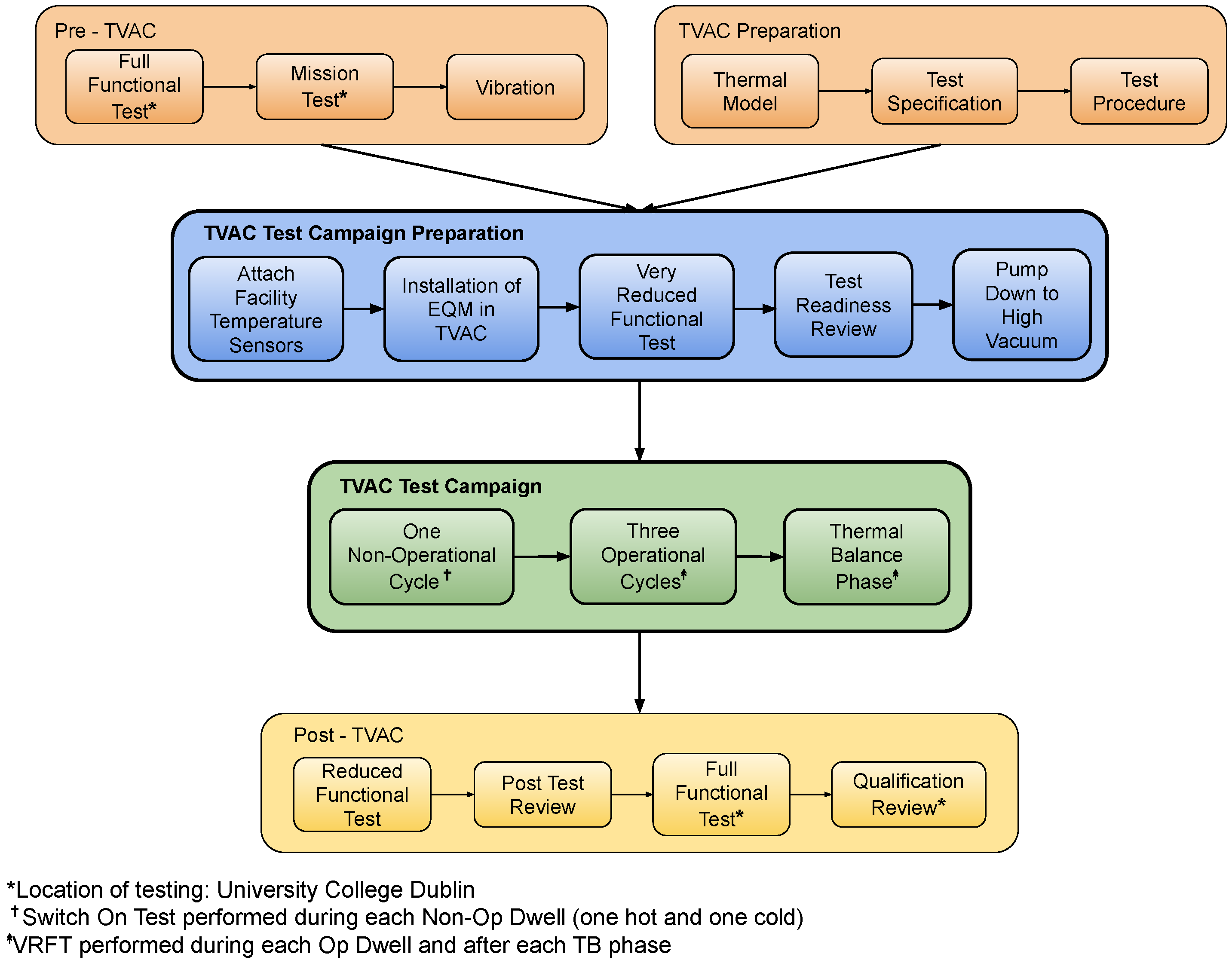
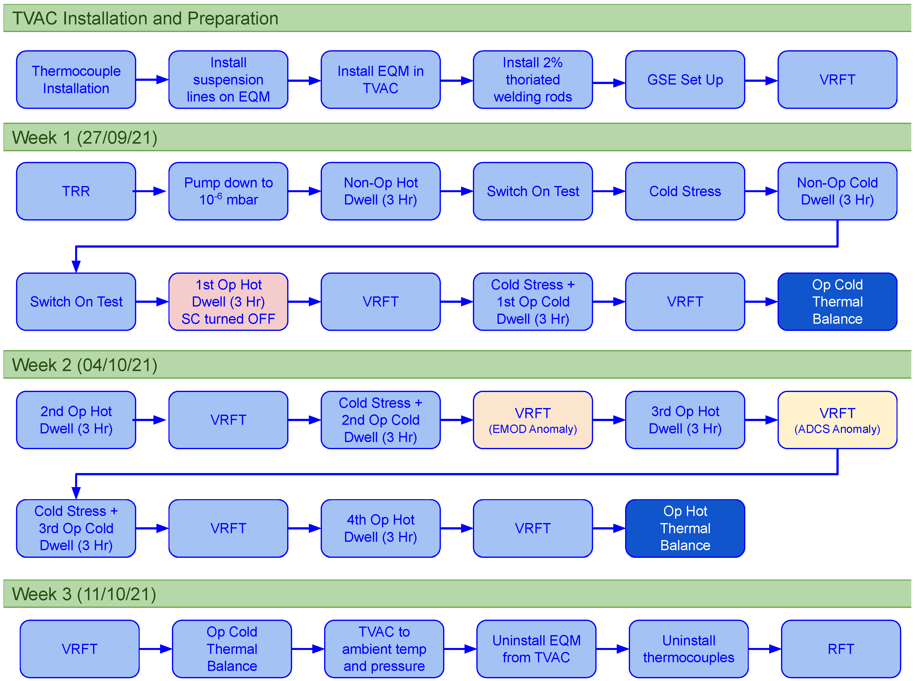
2.3. Test Plan
2.4. Functional Test Description
3. EQM Thermal Test Equipment Set Up
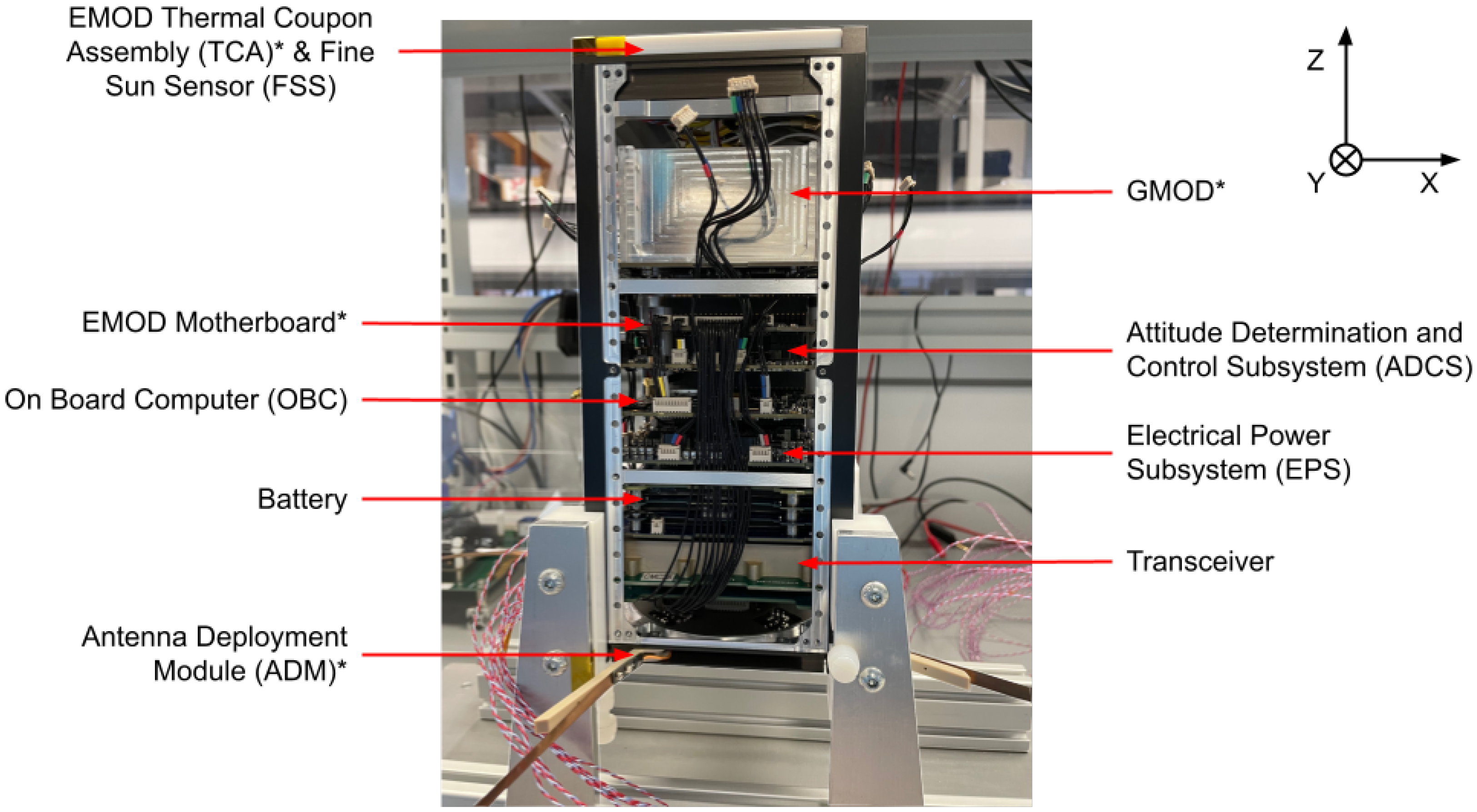
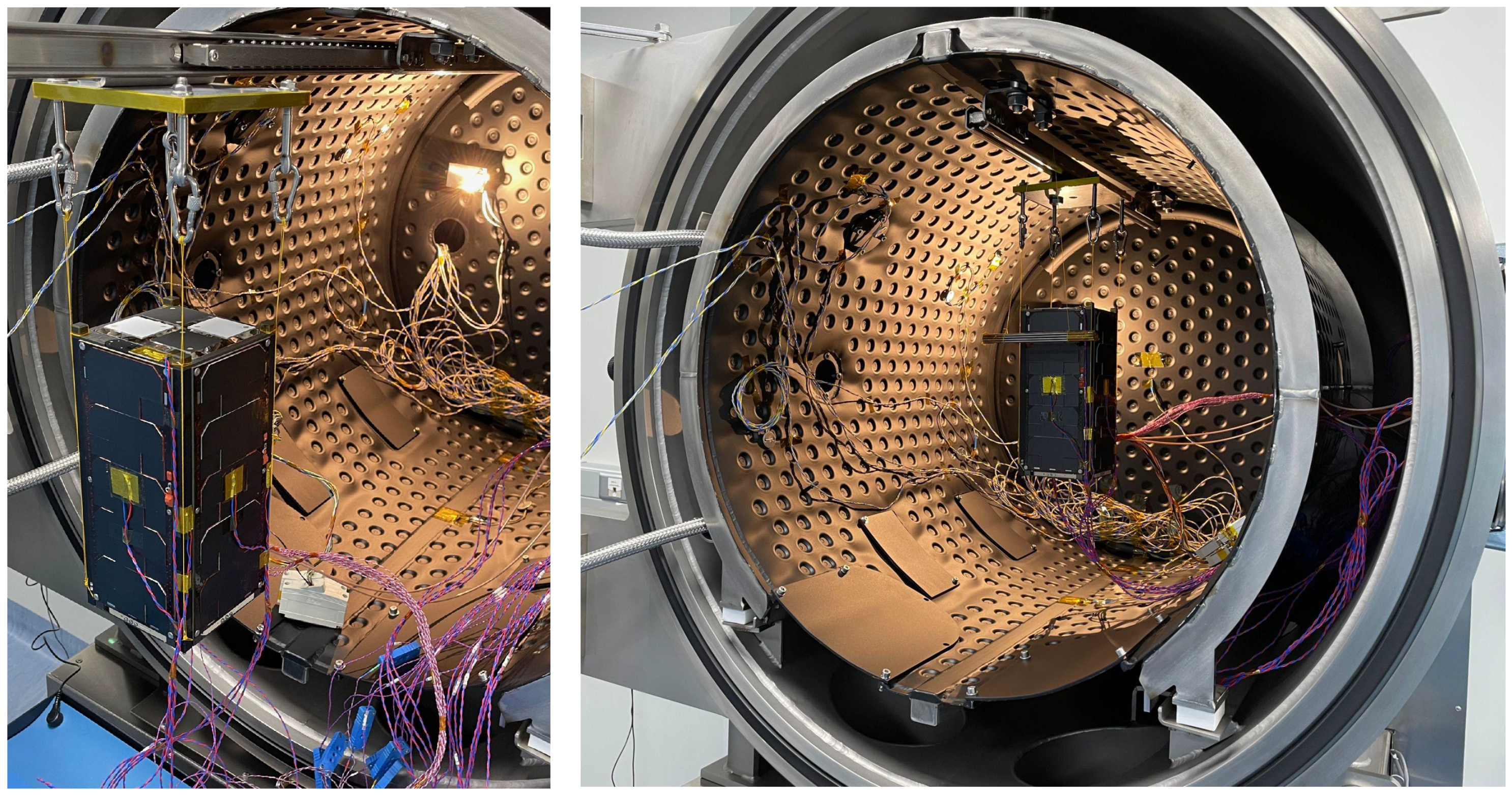
3.1. EIRSAT-1 EQM Thermal Test Configuration
3.2. TVAC Chamber and Instrumentation
3.3. Mechanical Ground Support Equipment
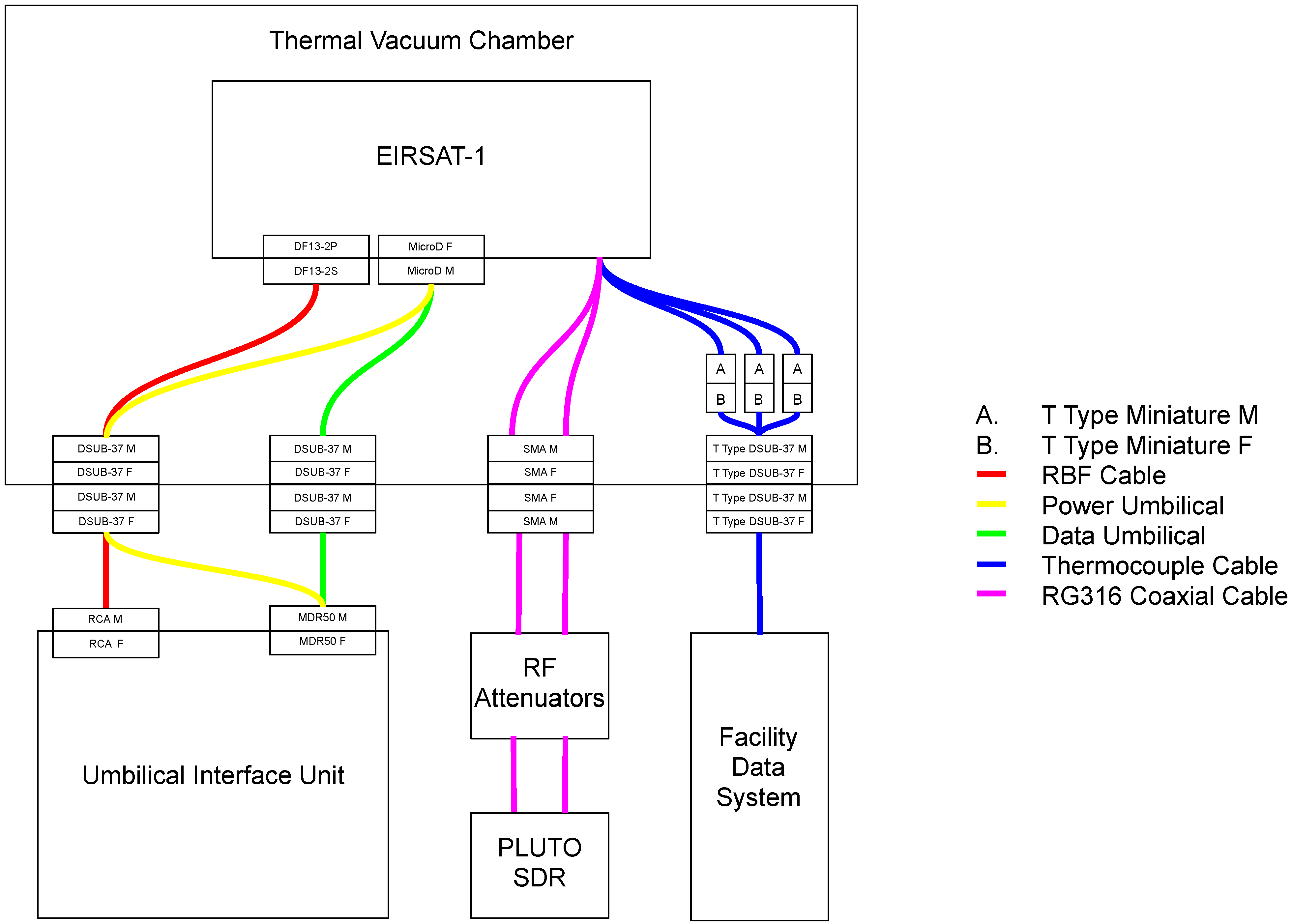
3.4. Electrical Ground Support Equipment
4. EQM Thermal Test Campaign Results
- The difference in temperature between the CSF sensors on the TVAC shroud and the TRP located on the external rail of EIRSAT-1.
- The offset between the sensors on the internal components and the external components of EIRSAT-1.
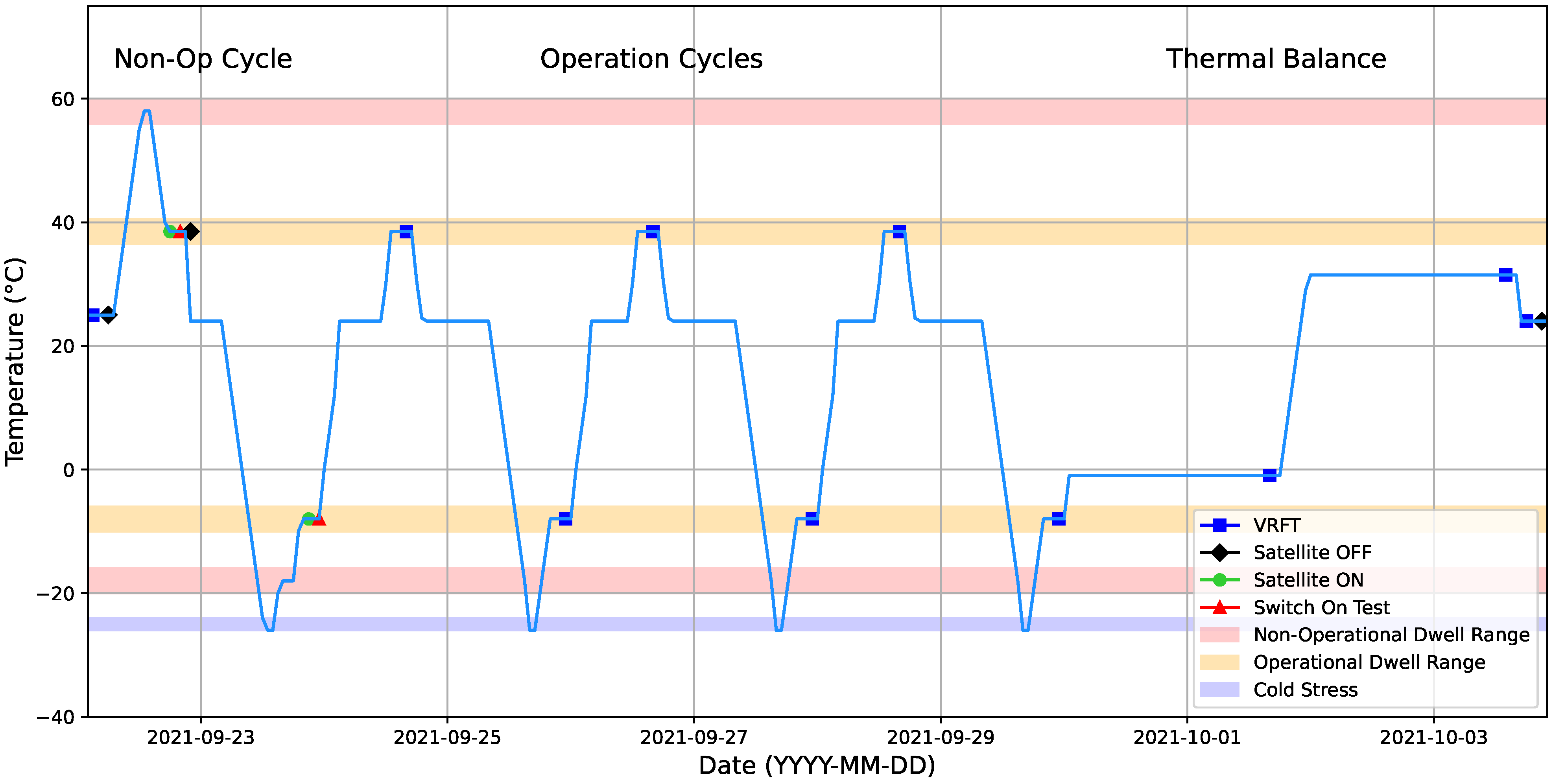
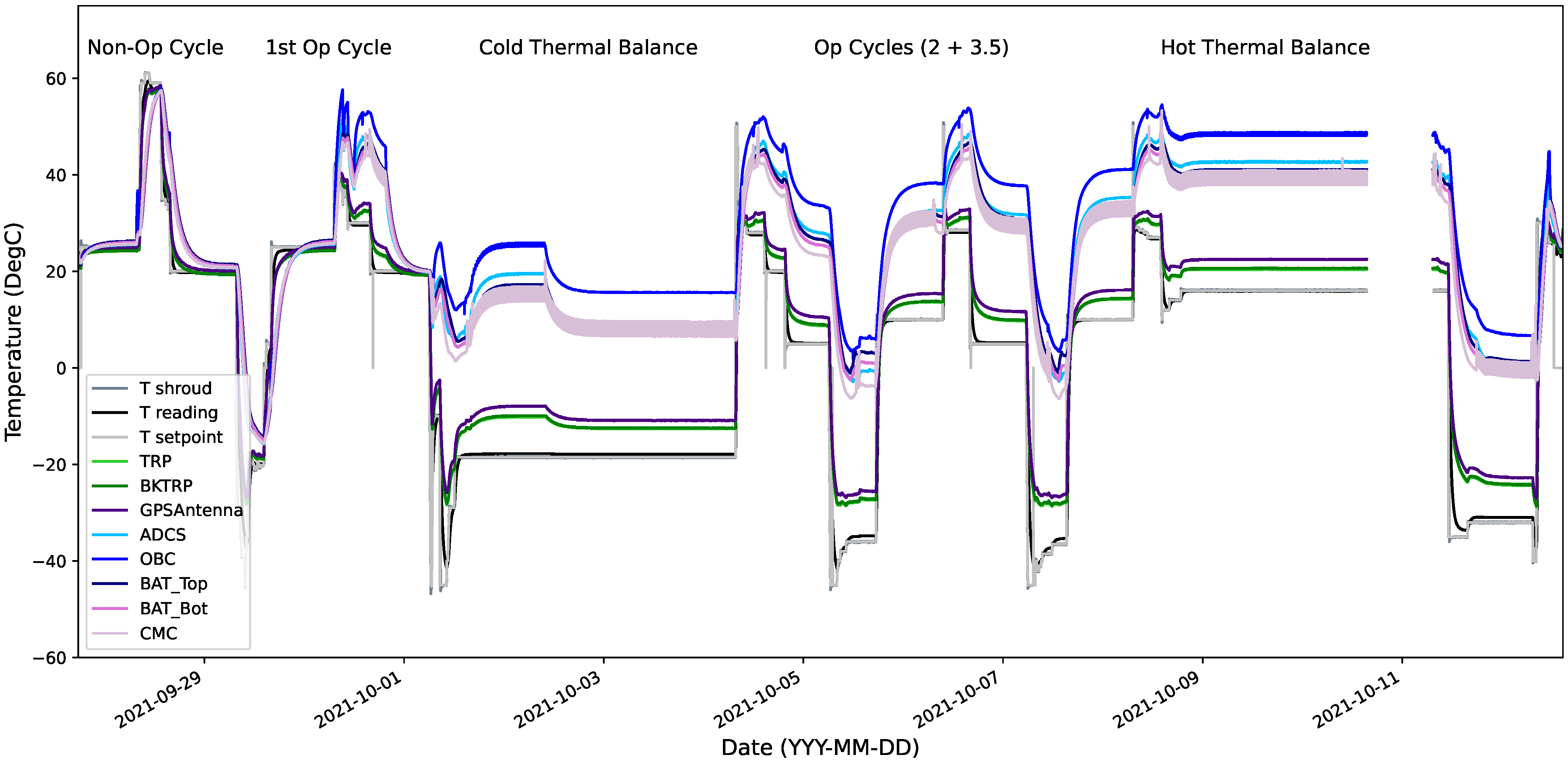
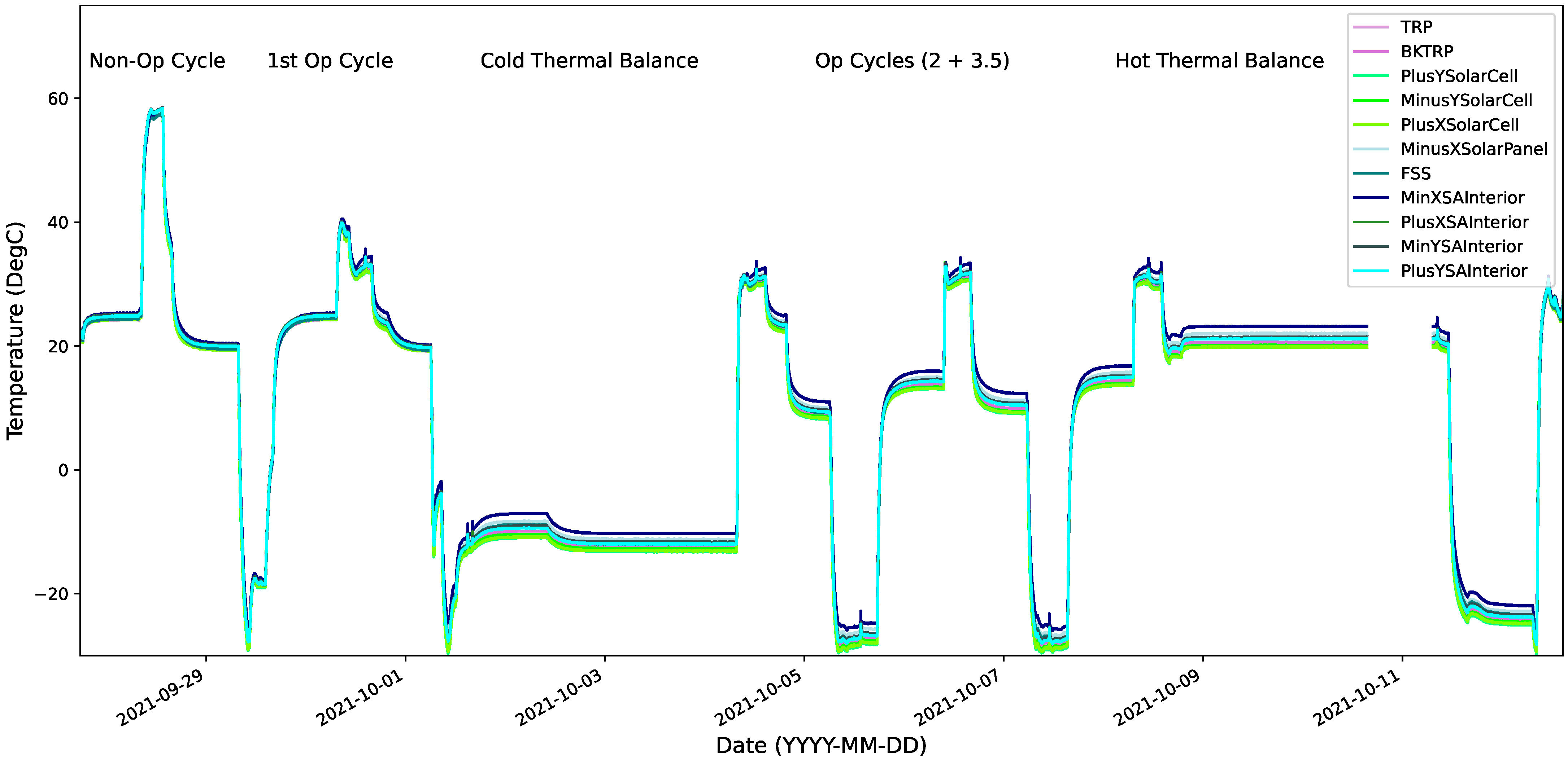
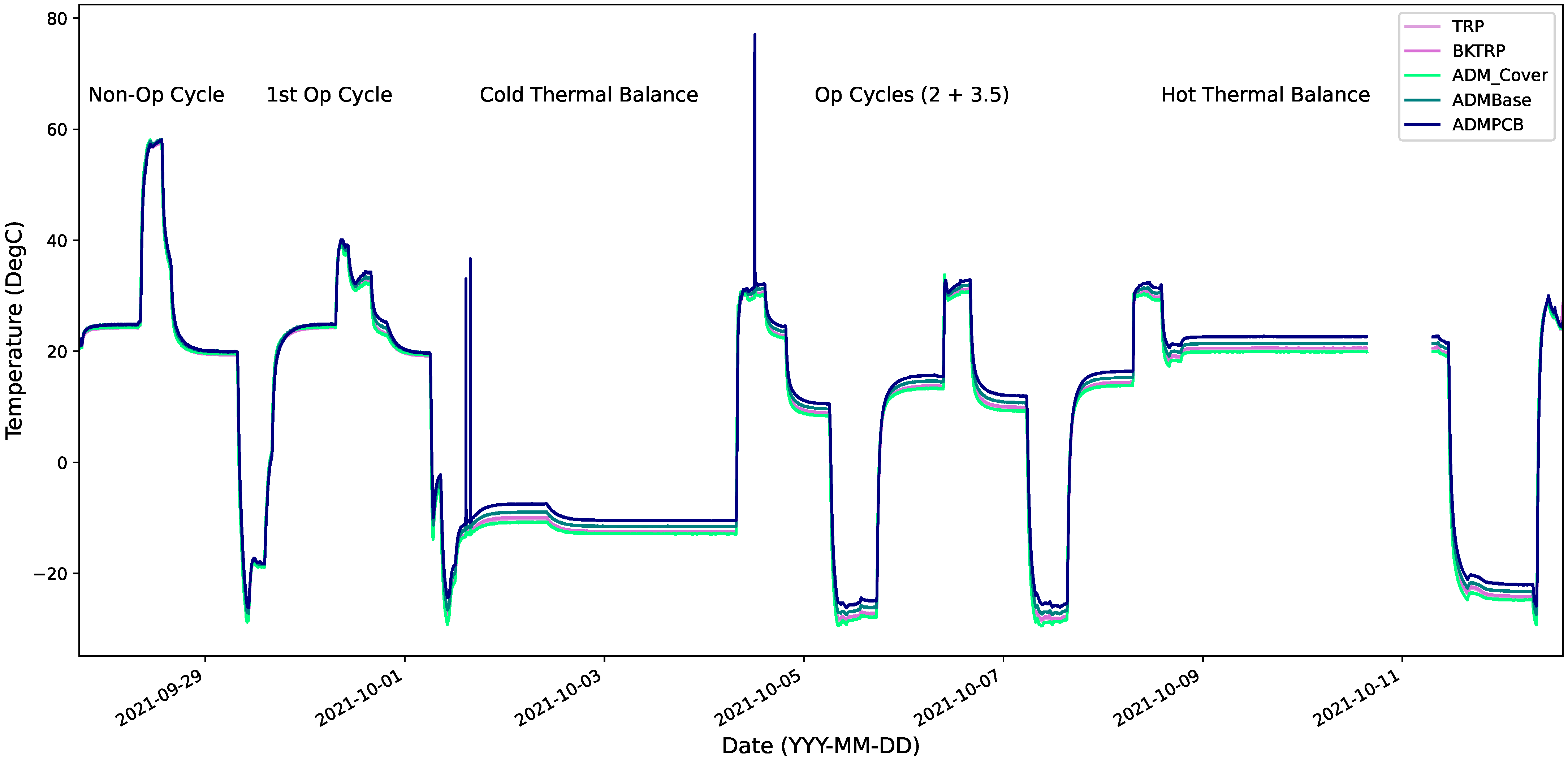
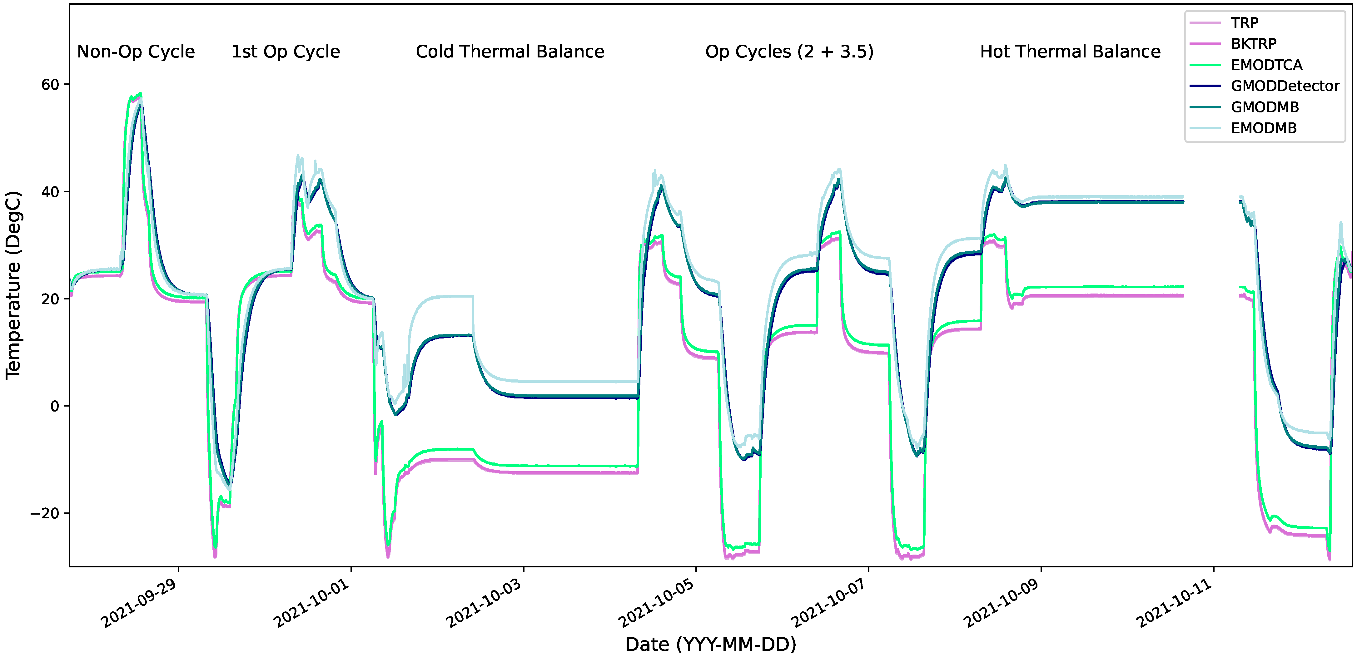
4.1. Thermal Test Overview
4.1.1. Thermocouple Calibration Issue
4.1.2. Non-Operational Phases
4.1.3. First Operational Phase
4.1.4. Cold Thermal Balance Phase
- S/C in nominal mode with GMOD and EMOD ON and in idle mode i.e., no experiment running. FSS was on, RF was enabled, and the ADCS Manager was enabled, meaning that the GPS was turned on for 2 min every 20 min. Charging was active and in end of charge mode.
- S/C in safe mode so all payloads are powered off, and ADCS Manager is off. RF was enabled. Charging was active and in end of charge mode.
4.1.5. Remaining Operational Phases
4.1.6. Hot Thermal Balance Phase and Post Test Review
4.2. VRFT Results
4.2.1. Battery Temperature Limit Anomaly
4.2.2. EMOD Data Transmission Anomaly
4.2.3. ADCS Gyro Communications Anomaly
4.2.4. CMC “Check 9” Anomaly
4.3. Post TVAC RFT
- The GMOD functional test was completed with the modified automated script where the new configuration file for the ASIC registers was uploaded. With the new ASIC configuration, GMOD successfully passed its functional test and produced a spectrum and light curve.
- After the EMOD anomaly investigation, the EMOD functional test script was run twice, first with the original firmware (v2.2.9) on the EMOD MB and then again with the new firmware (v2.2.10). The EMOD experiment functional test was passed with both firmware versions in ambient conditions. The new firmware (v2.2.10) was left on the EMOD MB as this version performed reliably in both ambient and high stress environments.
- An additional ADCS test was performed in an attempt to recreate the gyro communications anomaly observed in the TVAC. A script was developed to instruct the ADCS MB to transition between different modes and check the gyro error flags after each transition to see if they had been raised. The error flags were not raised when the script was run and it was concluded that the anomaly investigation should continue in the cleanroom in UCD and the thermal test campaign could be closed out with a successful RFT.
5. Lessons Learned
- Objectives of Thermal Test Campaign: Initially, the team considered the main objective of the system-level thermal test to be stressing of the spacecraft by thermal cycling between hot and cold. However, in preparing and executing the test campaign, the lesson learned was that the thermal vacuum test is primarily a functional test of the system. The objective is to allow as many subsystems as possible to stabilise at their expected operational extremes of temperature, both hot and cold, so that functional tests may be carried out in these space representative conditions and any anomalous behaviour may be detected and investigated. For a CubeSat, this can be challenging as the test item is physically quite small and does not usually have many active heating or cooling mechanisms on board. Therefore, stabilising the external parts of the satellite at their operational extremes can be difficult while respecting the temperature limits of internal components. Typically the dwell temperatures are limited by the more temperature sensitive internal components. The limiting subsystem in the case of EIRSAT-1 was the battery.
- Importance of Thermal Modelling: A thermal analysis of EIRSAT-1 was used to help define the dwell temperatures and durations for the thermal test. Early during the operational cycles, it became clear that this model and the simulations carried out on the model did not accurately represent the conditions in the TVAC of the dissipation of the satellite in different modes of operation. Ultimately this led to a redefinition of the dwell temperatures early in the test and the battery temperature limit anomaly discussed in Section 4.2.1. The EIRSAT-1 thermal analysis focused mainly on a transient analysis of the satellite in orbit. While this is important for finding the operational limits of different components, this test highlighted the equal importance of steady-state thermal analyses of the satellite while in different modes of dissipation. The steady state analyses are important both for the definition dwell temperatures during TVAC tests and for correlation with data collected in any thermal balance phases. Finally, the creation of such a high fidelity thermal model, capable of making accurate predictions would require a continuous effort throughout the life of the project. Therefore, thermal modelling should not be thought of as something that is required only at the early or design phases of a project but requires continuous updating as the design matures, the understanding of the system improves, and test data is available to correlate with the model.
- Addition of an Initial Operational Thermal Balance Phase in Future Tests: The resources and expertise required to carry out thermal modelling to the high fidelity described above are often not available to educational CubeSat teams. Ideally, the results of the TBal tests from this campaign will be used to refine the current thermal model of the S/C. In the case that time and resources do not support this, the following alternative approach has been suggested. For the EIRSAT-1 FM thermal test an initial thermal balance phase(s) at ambient temperature will be added to gather data on the temperature differences between subsystems and components with on-board dissipation. This data can then be used to adjust dwell temperatures before cycling.
- Battery Charging Profile: Linked to the above point, the charging profile was not well defined prior to the campaign. The rate of charging implemented at the beginning of the campaign introduced a non-negligible impact on the dissipation of the test item which contributed to reaching the battery temperature limits during cycling. For the FM campaign, a charging plan will be well defined for the duration of the test and a limit on the rate of charging will be implemented.
- Automated Test Scripts: The automated test scripts in Python were developed in the month before the thermal test campaign and proved to be beneficial. The VRFTs could be completed within two hours, confirming the functionality of all the subsystems in an efficient and replicable manner. The GMOD and EMOD anomalies were raised when the test scripts terminated early due to unexpected behaviour from the payloads. The FM FFT and ETC will make use of improved automated test scripts to streamline the testing process.
- Experiment Firmware Flashing: It was important in both anomaly investigations for EMOD and GMOD that the firmware on the experiment motherboard could be flashed via the OBC. A new firmware with a lower baudrate restored EMOD operations. The flashing of firmware to GMOD aided the understanding of the unusual behaviour of the experiment and that it was not related to the firmware. Without this capability, there would be no way to fix firmware during thermal testing without opening the chamber.
- Pass/Fail Criteria: During the PTR, the pass/fail criteria of the test campaign were reviewed before returning to ambient conditions to ensure all the objectives of the test campaign were achieved. An example of a poor pass/fail criteria is that all functional tests must be passed for the test campaign to be considered successful. It is inevitable that some anomalies will be encountered during these test campaigns, but it should not automatically result in the campaign not being considered successful. In writing the FM pass/fail criteria, the team will carefully consider the impact they will have on the formal evaluation of the success of the test campaign.
- Schedule: The three-week schedule for the thermal test campaign was optimistic and had no margin for anomaly investigations or the required increased dwell times. The entire environmental test campaign was scheduled to be four weeks, but an extra week was added on to investigate issues that arose during the vibration campaign. In the original plan, the TVAC was to be returned to ambient temperature over the weekend. To ensure the TBal phases could be performed, they had to be completed over the weekend. The test operators ended up spending long days in the cleanroom in order to complete all the functional tests within the window the EIRSAT-1 project had booked at the CSF. For FM a schedule will be developed that includes margin for anomaly investigations.
- Pre-Travel Checklists: One of the cables required for the configuration of the satellite in the TVAC was not packed and introduced a small delay in commencing the thermal test campaign. While a checklist was made by the team prior to the test campaign, it was not strictly checked off while packing and preparing for travel. The FM checklist will be checked off and reviewed prior to travel to ensure nothing is forgotten.
6. Future Work
7. Conclusions
Author Contributions
Funding
Institutional Review Board Statement
Informed Consent Statement
Data Availability Statement
Acknowledgments
Conflicts of Interest
Abbreviations
| ADCS | Attitude determination and control system |
| ADM | Antenna Deployment Module |
| ASIC | Application Specific Integrated Circuit |
| COTS | Commercial off-the-shelf |
| CSF | CubeSat Support Facility |
| DTMF | Dual-tone Multi-frequency |
| ECSS | European Cooperation for Space Standardisation |
| EGSE | Electrical ground support equipment |
| EIRSAT-1 | Educational Irish Research Satellite |
| EMOD | Enbio Module |
| EPS | Electrical power supply |
| ESA | European Space Agency |
| EQM | Engineering qualification model |
| ETC | Environmental Test Campaign |
| FFT | Full Functional Test |
| FM | Flight model |
| FSS | Fine Sun Sensor |
| FYS! | Fly Your Satellite! |
| GMOD | Gamma-ray Module |
| GRB | Gamma-ray Burst |
| GSE | Ground Support Equipment |
| IUT | Item Under Test |
| LEO | Low Earth Orbit |
| MB | Motherboard |
| MGSE | Mechanical Ground Support Equipment |
| MT | Mission Test |
| MTQ | Magnetorquers |
| NCR | Non-Conformance Report |
| OBC | On-Board Computer |
| PCB | Printed Circuit Board |
| PTR | Post Test Review |
| RBF | Remove Before Flight |
| RF | Radio Frequency |
| RFT | Reduced Functional Test |
| RTD | Resistance Temperature Detector |
| S/C | Spacecraft |
| TBal | Thermal Balance |
| TC | Telecommand |
| TSpe | Test Specification |
| TRP | Temperature Reference Point |
| TRPT | Test Report |
| TRR | Test Readiness Review |
| TVAC | Thermal Vacuum |
| UCD | University College Dublin |
| UIU | Umbilical Interface Unit |
| VRFT | Very Reduced Functional Test |
| WBC | Wave Based Control |
References
- Heidt, H.; Puig-Suari, J.; Moore, A.; Nakasuka, S.; Twiggs, R. CubeSat: A New Generation of Picosatellite for Education and Industry Low-Cost Space Experimentation. In Proceedings of the 13th Annual AIAA/USU Small Satellite Conference, Logan, UT, USA, 23–26 August 1999. [Google Scholar]
- The CubeSat Program. CubeSat Design Specification Rev. 14; Technical Report CP-CDS-R14; California Polytechnic State University (Cal Poly): San Luis Obispo, CA, USA, 2020. [Google Scholar]
- Nieto-Peroy, C.; Emami, M.R. CubeSat Mission: From Design to Operation. Appl. Sci. 2019, 9, 3110. [Google Scholar] [CrossRef] [Green Version]
- Twiggs, R. Origin of CubeSat. In Small Satellite: Past, Present and Future; Helvajian, H., Janson, S.W., Eds.; The Aerospace Press: El Segundo, CA, USA, 2008; Chapter 5; pp. 151–173. [Google Scholar]
- Swartwout, M. Reliving 24 Years in the next 12 Minutes: A Statistical and Personal History of University-Class Satellites. In Proceedings of the 32nd Annual AIAA/USU Small Satellite Conference, Logan, UT, USA, 4–9 August 2018. [Google Scholar]
- Suhadis, N.M. Statistical Overview of CubeSat Mission. In Proceedings of the International Conference of Aerospace and Mechanical Engineering 2019, Penang, Malaysia, 20–21 November 2019; Rajendran, P., Mazlan, N.M., Rahman, A.A.A., Suhadis, N.M., Razak, N.A., Abidin, M.S.Z., Eds.; Springer: Singapore, 2020; pp. 563–573. [Google Scholar]
- Kulu, E. Nanosatellite and CubeSat Database. Available online: https://www.nanosats.eu/database (accessed on 24 February 2021).
- Serjeant, S.; Elvis, M.; Tinetti, G. The future of astronomy with small satellites. Nat. Astron. 2020, 4, 1031–1038. [Google Scholar] [CrossRef]
- Liddle, J.; Holt, A.; Jason, S.J.; O’Donnell, K.A.; Stevens, E.J. Space science with CubeSats and nanosatellites. Nat. Astron. 2020, 4, 1026–1030. [Google Scholar] [CrossRef]
- Deepak, R.A.; Twiggs, R.J. Thinking Outside the Box: Space Science beyond the CubeSat. J. Small Satell. 2012, 1, 3–6. [Google Scholar]
- Mero, B.; Quillien, K.; McRobb, M.; Chesi, S.; Marshall, R.; Gow, A.; Clark, C.; Anciaux, M.; Cardoen, P.; Keyser, J.D.; et al. PICASSO: A State of the Art CubeSat. In Proceedings of the 29th Annual AIAA/USU Small Satellite Conference, Logan, UT, USA, 8–13 August 2015. [Google Scholar]
- Straub, J.; Villela, T.; Costa, C.A.; Brandão, A.M.; Bueno, F.T.; Leonardi, R. Towards the Thousandth CubeSat: A Statistical Overview. Int. J. Aerosp. Eng. 2019, 2019, 5063145. [Google Scholar] [CrossRef]
- Swartwout, M. The First One Hundred CubeSats: A Statistical Look. J. Small Satell. 2013, 2, 213–233. [Google Scholar]
- Perumal, R.P.; Voos, H.; Dalla Vedova, F.; Moser, H. Small Satellite Reliability: A Decade in Review. In Proceedings of the AIAA/USU Conference on Small Satellites, Virtual, 7–12 August 2021. [Google Scholar]
- Alanazi, A.; Straub, J. Engineering Methodology for Student-Driven CubeSats. Aerospace 2019, 6, 54. [Google Scholar] [CrossRef] [Green Version]
- Monteiro, J.P.; Rocha, R.M.; Silva, A.; Afonso, R.; Ramos, N. Integration and Verification Approach of ISTSat-1 CubeSat. Aerospace 2019, 6, 131. [Google Scholar] [CrossRef] [Green Version]
- Viquerat, A.; Schenk, M.; Lappas, V.; Sanders, B. Functional and Qualification Testing of the InflateSail Technology Demonstrator. In Proceedings of the 2nd AIAA Spacecraft Structures Conference (AIAA SciTech), Kissimmee, FL, USA, 5–9 January 2015; American Institute of Aeronautics and Astronautics Inc. (AIAA): Reston, VA, USA, 2015. [Google Scholar] [CrossRef] [Green Version]
- Murphy, D.; Joe, F.; Thompson, J.W.; Doyle, M.; Erkal, J.; Gloster, A.; O’Toole, C.; Salmon, L.; Sherwin, D.; Walsh, S.; et al. EIRSAT-1—The Educational Irish Research Satellite. In Proceedings of the 2nd Symposium on Space Educational Activities, Budapest, Hungary, 11–13 April 2018; Bacsárdi, L., Ed.; Budapest University of Technology and Economics: Budapest, Hungary, 2018; pp. 201–205. [Google Scholar]
- Vanreusel, J. Fly Your Satellite! The ESA Academy CubeSats programme. In Proceedings of the ITU Symposium & Workshop on Small Satellite Regulation and Communication Systems, Santiago de Chile, Chile, 7–9 November 2016. [Google Scholar]
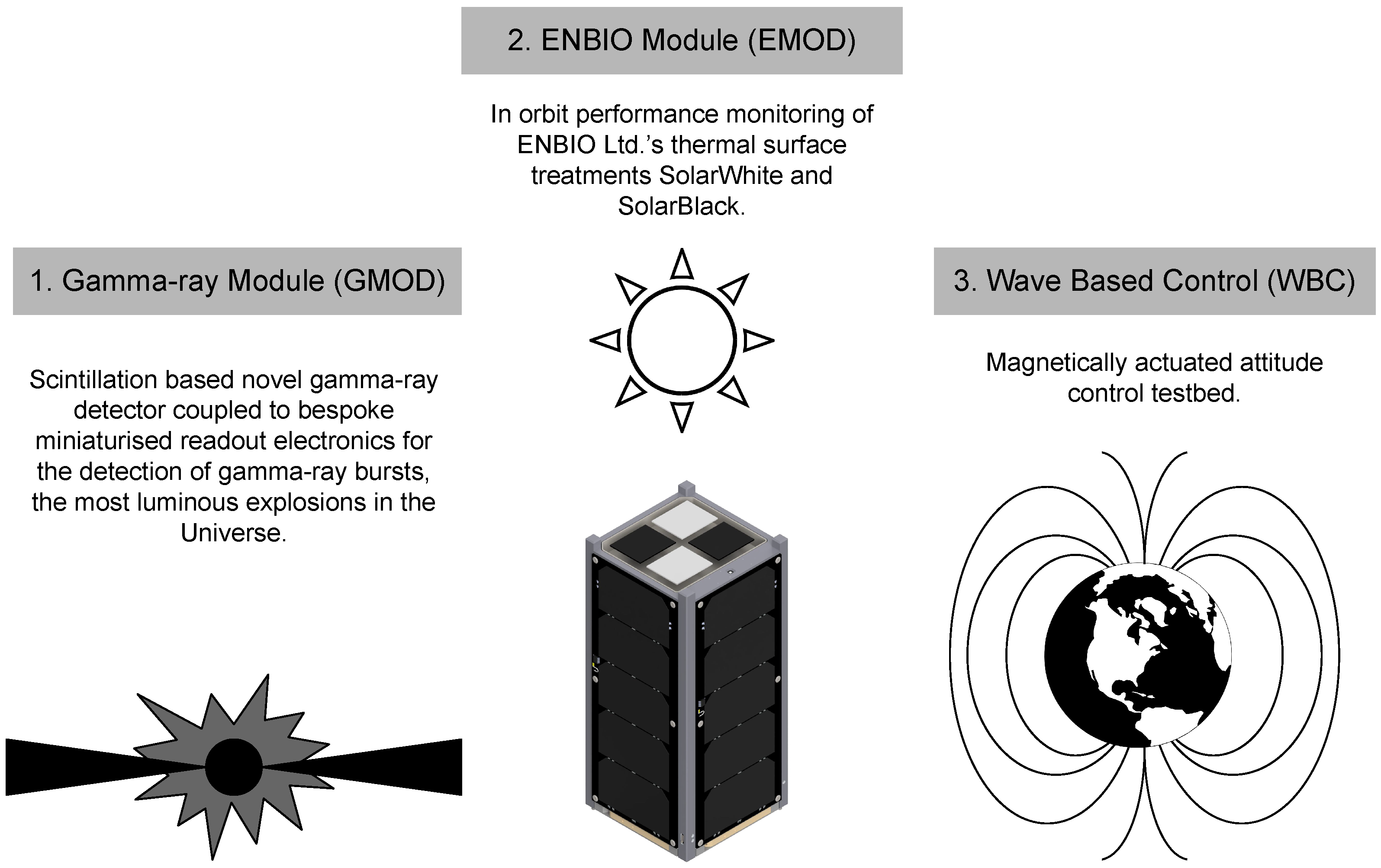
- Murphy, D.; Ulyanov, A.; McBreen, S.; Doyle, M.; Dunwoody, R.; Mangan, J.; Thompson, J.; Shortt, B.; Martin-Carrillo, A.; Hanlon, L. A compact instrument for gamma-ray burst detection on a Cubesat platform I: Design drivers and expected performance. Exp. Astron. 2021, 52, 59–84. [Google Scholar] [CrossRef]
- Murphy, D.; Ulyanov, A.; McBreen, S. A compact instrument for gamma-ray burst detection on a Cubesat platform II: Detailed design, assembly and validation. Exp. Astron. 2021; under review. [Google Scholar]
- Ulyanov, A.; Morris, O.; Hanlon, L.; McBreen, S.; Foley, S.; Roberts, O.J.; Tobin, I.; Murphy, D.; Wade, C.; Nelms, N.; et al. Performance of a monolithic LaBr3:Ce crystal coupled to an array of silicon photomultipliers. Nucl. Instrum. Methods Phys. Res. A 2016, 810, 107–119. [Google Scholar] [CrossRef]
- Ulyanov, A.; Morris, O.; Roberts, O.J.; Tobin, I.; Hanlon, L.; McBreen, S.; Murph, D.; Nelms, N.; Shortt, B. Localisation of gamma-ray interaction points in thick monolithic CeBr3 and LaBr3:Ce scintillators. Nucl. Instrum. Methods Phys. Res. A 2017, 844, 81–89. [Google Scholar] [CrossRef] [Green Version]
- Mangan, J.; Murphy, D.; Dunwoody, R.; Doyle, M.; Ulyanov, A.; Hanlon, L.; Shortt, B.; McBreen, S.; Emam, M.; Erkal, J.; et al. Embedded Firmware Development for a Novel CubeSat Gamma-Ray Detector. arXiv 2021, arXiv:2111.03128. [Google Scholar]
- Vedrenne, G.; Atteia, J.L. Gamma-Ray Bursts: The Brightest Explosions in the Universe. Phys. Today 2010, 63, 56. [Google Scholar]
- On Semiconductor. J-Series SiPM Sensors Datasheet—Revision 6; Semiconductor Components Industries, LLC: Phoenix, AZ, USA, 2018. [Google Scholar]
- Ulyanov, A.; Murphy, D.; Fredriksen, A.; Ackermann, J.; Meier, D.; Nelms, N.; Shortt, B.; McBreen, S.; Hanlon, L. Using the SIPHRA ASIC with an SiPM array and scintillators for gamma spectroscopy. In Proceedings of the 2017 IEEE Nuclear Science Symposium and Medical Imaging Conference (NSS/MIC), Atlanta, GA, USA, 21–28 October 2017; pp. 1–3. [Google Scholar]
- Müller, D.; St. Cyr, O.C.; Zouganelis, I.; Gilbert, H.R.; Marsden, R.; Nieves-Chinchilla, T.; Antonucci, E.; Auchère, F.; Berghmans, D.; Horbury, T.S.; et al. The Solar Orbiter mission. Astron. Astrophys. 2020, 642, A1. [Google Scholar] [CrossRef]
- O’Connor, W.; de la Flor, F.R.; McKeown, D.; Feliu, V. Wave-based control of non-linear flexible mechanical systems. Nonlinear Dyn. 2008, 57, 113–123. [Google Scholar] [CrossRef]
- Sherwin, D.; Thompson, J.; McKeown, D.; O’Connor, W.; Sosa, V.U. Wave-based attitude control of EIRSAT-1, 2U cubesat. In Proceedings of the 2nd Symposium on Space Educational Activities, Budapest, Hungary, 11–13 April 2018; Bacsárdi, L., Ed.; Budapest University of Technology and Economics: Budapest, Hungary, 2018; pp. 273–277. [Google Scholar]
- Thompson, J.; Murphy, D.; Erkal, J.; Flanagan, J.; Doyle, M.; Gloster, A.; O’Toole, C.; Salmon, L.; Sherwin, D.; Walsh, S.; et al. Double dipole antenna deployment system for EIRSAT-1, 2U CubeSat. In Proceedings of the 2nd Symposium on Space Educational Activities, Budapest, Hungary, 11–13 April 2018; Bacsárdi, L., Ed.; Budapest University of Technology and Economics: Budapest, Hungary, 2018; pp. 221–225. [Google Scholar]
- Doyle, M.; Gloster, A.; O’Toole, C.; Mangan, J.; Murphy, D.; Dunwoody, R.; Emam, M.; Erkal, J.; Flanaghan, J.; Fontanesi, G.; et al. Flight software development for the EIRSAT-1 mission. In Proceedings of the 3rd Symposium on Space Educational Activities, Leicester, UK, 16–18 September 2019. [Google Scholar]
- Gamble, K.; Lightsey, G. Application of Risk Management to University CubeSat Missions. J. Small Satell. 2013, 2, 147–160. [Google Scholar]
- Menchinelli, A.; Ingiosi, F.; Pamphili, L.; Marzioli, P.; Patriarca, R.; Costantino, F.; Piergentili, F. A Reliability Engineering Approach for Managing Risks in CubeSats. Aerospace 2018, 5, 121. [Google Scholar] [CrossRef] [Green Version]
- Latachi, I.; Rachidi, T.; Karim, M.; Hanafi, A. Reusable and Reliable Flight-Control Software for a Fail-Safe and Cost-Efficient Cubesat Mission: Design and Implementation. Aerospace 2020, 7, 146. [Google Scholar] [CrossRef]
- Walsh, S.; Murphy, D.; Doyle, M.; Reilly, J.; Thompson, J.; Dunwoody, R.; Erkal, J.; Finneran, G.; Fontanesi, G.; Mangan, J.; et al. Development of the EIRSAT-1 CubeSat through Functional Verification of the Engineering Qualification Model. Aerospace 2021, 8, 254. [Google Scholar] [CrossRef]
- Walsh, S.; Murphy, D.; Doyle, M.; Thompson, J.; Dunwoody, R.; Emam, M.; Erkal, J.; Flanagan, J.; Fontanesi, G.; Gloster, A.; et al. Assembly, integration, and verification activities for a 2U CubeSat, EIRSAT-1. In Proceedings of the 3rd Symposium on Space Educational Activities, Leicester, UK, 16–18 September 2019. [Google Scholar]
- Doyle, M.; Dunwoody, R.; Finneran, G.; Murphy, D.; Reilly, J.; Thompson, J.; Walsh, S.; Erkal, J.; Fontanesi, G.; Mangan, J.; et al. Mission testing for improved reliability of CubeSats. In Proceedings of the International Conference on Space Optics—ICSO 2020, Online, 30 March–2 April 2021; Cugny, B., Sodnik, Z., Karafolas, N., Eds.; International Society for Optics and Photonics, SPIE: Bellingham, WA, USA, 2021; Volume 11852, pp. 2717–2736. [Google Scholar]
- Mangan, J.; Murphy, D.; Dunwoody, R.; Ulyanov, A.; Thompson, J.; Javaid, U.; O’Toole, C.; Doyle, M.; Emam, M.; Erkal, J.; et al. The environmental test campaign of GMOD: A novel gamma-ray detector. In Proceedings of the International Conference on Space Optics—ICSO 2020, Online, 30 March–2 April 2021; Cugny, B., Sodnik, Z., Karafolas, N., Eds.; International Society for Optics and Photonics, SPIE: Bellingham, WA, USA, 2021; Volume 11852, pp. 471–491. [Google Scholar] [CrossRef]
- ECSS Secretariat. Tailored ECSS Engineering Standards for In-Orbit Demonstration CubeSat Projects; ECSS Standard; European Cooperation for Space Standardisation: Noordwijk, The Netherlands, 2016. [Google Scholar]
- Bagagli, R.; Baldini, L.; Bellazzini, R.; Barbiellini, G.; Belli, F.; Borden, T.; Brez, A.; Brigida, M.; Caliandro, G.A.; Cecchi, C.; et al. Environmental tests of the flight GLAST LAT tracker towers. Nucl. Instrum. Methods Phys. Res. Sect. A Accel. Spectrom. Detect. Assoc. Equip. 2008, 584, 358–373. [Google Scholar] [CrossRef] [Green Version]
- You, Z. Chapter 5—Ground Tests of Micro/Nano Satellites. In Space Microsystems and Micro/Nano Satellites; Micro and Nano Technologies; Butterworth-Heinemann: Oxford, UK, 2018; pp. 147–166. [Google Scholar] [CrossRef]
- ESA Education CubeSat Support Facility. Available online: https://www.esa.int/Education/CubeSats_-_Fly_Your_Satellite/CubeSat_Support_Facility (accessed on 8 December 2021).
- ECSS Secretariat. ECSS Standard ECSS-E-ST-10-03C; Space Engineering: Testing. European Cooperation For Space Standardisation: Noordwijk, The Netherlands, 2012.
- Welch, J. Assessment of Thermal Balance Test Criteria Requirements on Test Objectives and Thermal Design. In Proceedings of the 46th International Conference on Environmental Systems, Vienna, Austria, 10–14 July 2016. [Google Scholar]
- Obiols-Rabasa, G.; Corpino, S.; Mozzillo, R.; Stesina, F. Lessons learned of a systematic approach for the e-st@r-II CubeSat environmental test campaign. In Proceedings of the 66th IAC International Astronautical Congress, Jerusalem, Israel, 12–16 October 2015. [Google Scholar]
- Del Castillo-Sancho, C.; Grassi, G.; Kinnaird, A.; Mills, A.; Palma, D. Lessons Learned from AIV in ESA’s Fly Your Satellite! Educational CubeSat Programme. In Proceedings of the AIAA/USU Conference on Small Satellites, Virtual, 7–12 August 2021. [Google Scholar]
- Fortescue, P.; Swinerd, G.; Stark, J. Spacecraft Systems Engineering, 4th ed.; Wiley: West Sussex, UK, 2011; Chapter 11. [Google Scholar]
- Tribble, A. The Space Environment: Implications for Spacecraft Design; Princeton University Press: Princeton, NJ, USA, 1995. [Google Scholar]
- Meseguer, J.; Pérez-Grande, I.; Sanz-Andrés, A. Spacecraft Thermal Control; Woodhead Publishing: Sawston, UK, 2012. [Google Scholar]
- Complete CAD-Based Thermal Engineering Tool Suite. Available online: https://www.crtech.com/products/thermal-desktop (accessed on 14 December 2021).
- ECSS Secretariat. ECSS Standard ECSS-E-ST-31C; Thermal Control. European Cooperation For Space Standardisation: Noordwijk, The Netherlands, 2008.
- Marshall, F.; Murphy, D.; Salmon, L.; O’Callaghan, D.; Doyle, M.; Reilly, J.; Dunwoody, R.; Erkal, J.; Finneran, G.; Fontanesi, G.; et al. Development of the Ground Segment Communication System for the EIRSAT-1 CubeSat. In Proceedings of the 16th International Conference of Space Operations 2021, Online, 3–5 May 2021; American Institute of Aeronautics and Astronautics: Reston, VA, USA, 2021. [Google Scholar]
- Grafana Labs. Available online: https://grafana.com/ (accessed on 10 January 2022).
- Thompson, J.; Reilly, J.; Murphy, D.; Salmon, L.; Doyle, M.; Dunwoody, R.; Rajagopalan Nair, R.; Erkal, J.; Finneran, G.; Mangan, J.; et al. Thermal Characterization Testing of a Robust and Reliable Thermal Knife HDRM (Hold Down and Release Mechanism) for CubeSat Deployables. In Proceedings of the 4th Symposium on Space Educational Activities, Barcelona, Spain, 27–29 April 2022. [Google Scholar]
- Ibrahim, R.O.; Abd El-Azeem, S.; El-Ghanam, S.; Soliman, F. Studying the operation of MOSFET RC-phase shift oscillator under different environmental conditions. Nucl. Eng. Technol. 2020, 52, 1764–1770. [Google Scholar] [CrossRef]


| Test Activity | Description |
|---|---|
| FFT | The full functional test fully assesses the performance of the system and also verifies functional requirements. |
| RFT | The reduced functional test focuses on mission-crucial hardware functions and includes a subset of tests performed in the FFT to verify the performance of the spacecraft after environmental tests. |
| VRFT | The very reduced functional test contains a subset of the tests in the RFT; the selection criteria was that the test could be completed while the satellite was installed in the thermal vacuum chamber. |
| Item | Operational | Non-Operational | ||
|---|---|---|---|---|
| Min (°C) | Max (°C) | Min (°C) | Max (°C) | |
| SiPM | −45 | +85 | −45 | +85 |
| GMOD CPLD | −40 | +85 | −40 | +105 |
| GMOD Microcontroller | −40 | +85 | −40 | +105 |
| EMOD Microcontroller | −40 | +85 | −40 | +105 |
| OBC | −40 | +80 | −40 | +85 |
| ADCS Motherboard | −40 | +80 | −40 | +85 |
| EPS | −40 | +85 | −50 | +100 |
| Comms | −25 | +61 | −40 | +85 |
| Battery | −10 | +50 | −20 | +60 |
| Solar Arrays | −40 | +80 | −40 | +85 |
| Fine Sun Sensor | −30 | +85 | −30 | +85 |
| Orbital Parameter | EIRSAT-1 Value |
|---|---|
| Orbital Inclination (°) | 51.6 |
| Right Ascension of Ascending Node(°) | 315.8 |
| Argument of Periapsis (°) | 273.4 |
| Eccentricity | 0.001 |
| Altitude at Apogee (km) | 412.64 |
| Test Level | Temperature (°C) | Tolerance (°C) | TRP Range (°C) |
|---|---|---|---|
| Tmax, non-op | +56 | −0/+4 | +57 to +59 |
| Tmin, non-op | −16 | −4/+0 | −17 to −19 |
| Tmax, op | +36.5 | −0/+4 | +37.5 to 39.5 |
| Tmin, op | −6 | −4/+0 | −7 to −9 |
| Tmin, stress | −26 | −4/+0 | −27 to −29 |
| Tmax, TBal | +31.5 | −0/+4 | +32.5 to 34.5 |
| Tmin, TBal | −1 | −4/+0 | −2 to −4 |
| Parameter | Values |
|---|---|
| Temperature Gradient Range | 0.1 °C/min |
| Dwell Time | 120 min |
| Stress Dwell Time | ∼60 min |
| TBal Stabilisation | 0.5 K/4 h |
| Test Name | Test Description |
|---|---|
| ADM Primary Deployment Burn * | Primary resistors in ADM are burned, and successfully deploy the four antennas unless antennas have already been released. |
| ADM Secondary Deployment Burn * | Secondary resistors in ADM are burned, and successfully deploy the four antennas unless antennas have already been released. |
| Subsystem Power On * | To confirm all essential loads (EPS, BAT, CMC, ADCS, and OBC) are turned on upon power ON of the spacecraft, a telecommand (TC) is sent to the S/C to obtain the version parameter of each subsystem. |
| RBF Inhibit Insertion | Confirms the SC powers off and charging takes place when RBF pin is inserted and the SC powers on when RBF pin removed. |
| Inhibits Insertion | Ensures that the spacecraft does not power on when any one of the inhibits are activated. |
| DTMF Reset | Verifies that the receipt of the correct DTMF tones by the spacecraft resets the OBC. |
| Uplink/Downlink * | Verifies that a packet can be sent and received between the spacecraft and the ground station. |
| Beacon stop/start | Verifies that the beacon is transmitted once a minute and RF can be stopped upon command from GS. |
| ADCS On-board Sensors | ADCS bus voltages and currents checked. On-board magnetometers and rate gyroscopes are excited to check noise, polarity, and correct function. |
| ADCS External Sensors | Five coarse sun sensors and one fine sun sensor are all excited using a torch (Fenix LD22) to test functionality. |
| ADCS Magnetorquers (MTQs) * | Functionality confirmed by driving each coil at duty cycles of 100% in both directions for 20 s each. |
| OBC Reduced Mode Changes * | Verifies that the OBC can transition between different operational modes. Reduced as no transitions to/from WBC mode were made. |
| Temperature Sensors * | Read all temperature sensors (BAT, EPS, ADCS, magnetometers, gyro, CMC). |
| GMOD Functional * | Payload is power cycled to confirm configuration is correct after power on. GMOD experiment set up to stream data to the OBC to generate a spectrum and lightcurve using 2% thoriated rods as a gamma-ray source. |
| EMOD Functional * | Payload is power cycled to confirm configuration is correct after power on. EMOD experiment is set up to stream RTD readings to OBC. |
| Test Level | Temperature (°C) | Tolerance (°C) | TRP Range (°C) |
|---|---|---|---|
| Tmax, non-op | +56 | −0/+4 | +57 to +59 |
| Tmin, non-op | −16 | −4/+0 | −17 to −19 |
| Tmax, op | +28 | −0/+4 | +29 to +31 |
| Tmin, op | −6 | −4/+0 | −7 to −9 |
| Tmin, stress | −26 | −4/+0 | −27 to −29 |
| Tmax, TBal | +20 | −0/+4 | +21 to +23 |
| Tmin, TBal | −1 | −4/+0 | −2 to −4 |
| Subsystem | ADM | EMOD | GMOD | |||
|---|---|---|---|---|---|---|
| Test Activity | Primary deployment | Resistor burns | Payload power cycle | Read RTD measurements | Payload power cycle | Generate lightcurve and spectrum with a radioactive source |
| Ambient VRFT | — | — | — | — | ✓ | ✓ |
| Non-Op Hot Switch On Test | — | — | — | — | — | — |
| Non-Op Cold Switch On Test | — | — | — | — | — | — |
| Op Hot 1 VRFT | — | — | — | — | ✓ | ✓ |
| Op Cold 1 VRFT | ✓ | ✓ | — | — | ✓ | ✓ |
| Op Hot 2 VRFT | — | ✓ | ✓ | ✓ | ✓ | ✓ |
| Op Cold 2 VRFT | — | — | ✓ | ✓ | ✓ | ✓ |
| Op Hot 3 VRFT | — | — | ✓ | ✓ | ✓ | ✓ |
| Op Cold 3 VRFT | — | — | ✓ | ✓ | ✓ | ✓ |
| Op Hot 4 VRFT | — | — | ✓ | ✓ | ✓ | ✓ |
| Hot Thermal Balance VRFT | — | — | ✓ | ✓ | ✓ | ✓ |
| Post TVAC RFT | ✓ | ✓ | ✓ | ✓ | ✓ | ✓ |
| Anomaly | Documentation Required | Responsible |
|---|---|---|
| Battery Temperature Limit | Minor NCR | EIRSAT-1/ESA |
| EMOD Data Transmission | Major NCR | EIRSAT-1 |
| ADCS Gyro Comms Error Flags | Major NCR | EIRSAT-1 |
| CMC “Check 9” at low temperatures | Minor NCR | EIRSAT-1 |
| Loss of data due to CSF computer crash | Minor NCR | ESA |
Publisher’s Note: MDPI stays neutral with regard to jurisdictional claims in published maps and institutional affiliations. |
© 2022 by the authors. Licensee MDPI, Basel, Switzerland. This article is an open access article distributed under the terms and conditions of the Creative Commons Attribution (CC BY) license (https://creativecommons.org/licenses/by/4.0/).
Share and Cite
Dunwoody, R.; Reilly, J.; Murphy, D.; Doyle, M.; Thompson, J.; Finneran, G.; Salmon, L.; O’Toole, C.; Reddy Akarapu, S.K.; Erkal, J.; et al. Thermal Vacuum Test Campaign of the EIRSAT-1 Engineering Qualification Model. Aerospace 2022, 9, 99. https://doi.org/10.3390/aerospace9020099
Dunwoody R, Reilly J, Murphy D, Doyle M, Thompson J, Finneran G, Salmon L, O’Toole C, Reddy Akarapu SK, Erkal J, et al. Thermal Vacuum Test Campaign of the EIRSAT-1 Engineering Qualification Model. Aerospace. 2022; 9(2):99. https://doi.org/10.3390/aerospace9020099
Chicago/Turabian StyleDunwoody, Rachel, Jack Reilly, David Murphy, Maeve Doyle, Joseph Thompson, Gabriel Finneran, Lána Salmon, Conor O’Toole, Sai Krishna Reddy Akarapu, Jessica Erkal, and et al. 2022. "Thermal Vacuum Test Campaign of the EIRSAT-1 Engineering Qualification Model" Aerospace 9, no. 2: 99. https://doi.org/10.3390/aerospace9020099