Article

Cooperative Smooth Nonsingular Terminal Sliding Mode Guidance with Tracking Differentiator for Active Aircraft Defense

1
School of Astronautics, Northwestern Polytechnical University, Xi’an 710072, China
2
Unmanned System Research Institute, Northwestern Polytechnical University, Xi’an 710072, China
3
General Technology Department of Technical Weapons, China Academy of Launch Vehicle Technology, Beijing 100076, China
*
Author to whom correspondence should be addressed.
Aerospace 2022, 9(4), 221; https://doi.org/10.3390/aerospace9040221
Submission received: 27 February 2022 / Revised: 7 April 2022 / Accepted: 11 April 2022 / Published: 15 April 2022
(This article belongs to the Section Aeronautics)

Abstract

:
Aimed at the poor performance of guidance algorithms designed based on a linearized model in active defense under large leading angle deviation, both-way and one-way cooperative sliding mode guidance algorithms based on the smooth nonsingular terminal sliding mode for the defense missile are proposed. The relative kinematics and linearized models of the target, the active defense missile, and the attacking missile are established. In the design process, two smooth nonsingular terminal sliding mode surfaces are constructed based on zero-effort miss distance and zero-effort velocity, as well as their integral values. A tracking differentiator is introduced for excessive initial command deviation to meet the overload constraints of the active missile and the target. The sensitivity of guidance law to the estimated time-to-go error is reduced, and the target is allowed to perform an independent evasive maneuver. The effectiveness of the proposed guidance strategy is verified by numerical simulation and compared to the existing guidance strategies, the high accuracy, anti-chattering, and strong robustness of the proposed guidance algorithm are verified.

1. Introduction

Since the Gulf War, the seizure of air supremacy has been a key determinant of victory or defeat in modern warfare. In traditional air combat, when the aircraft is threatened by an air-to-air missile, the main measures to be taken are evasion maneuvers, deploying point or surface decoys, and so on. These methods can be summed up as passive defense measures because their starting point is to find effective evasive means. However, with the improvement of modern air-to-air missile operational performance and the intelligence level, passive defense measures are increasingly unable to ensure the safety of aircraft. Comparatively speaking, the target aircraft, especially a high-value target aircraft, can take active defense measures; for example, when it is tracked by an attacking missile, it can launch one or more active defense missiles from its own or its friendly platform to intercept the attacking missile while performing an evasion maneuver, which is called “three-body engagement.” Instead of a traditional one-on-one engagement scenario, a target aircraft (the target) and an active defense missile (the defense missile) are involved in the engagement.
Recently, the three-body engagement problem has received considerable attention. After the rapid development in recent years, research methods mainly include the line-of-sight instruction guidance method, the optimal control method, the differential game method, and so on.
Line-of-sight (LOS) guidance is actually the idea of the classic three-point guidance. From the point of view of the target and the defense missile, in order to protect the target and intercept the incoming missile, it is natural to keep the defense missile on the LOS between the missile and target so that the former will be intercepted by the defense missile before hitting the latter. Yamasaki and Takano [1] used the three-point guidance method to keep the defense missile on the LOS between the target and the interceptor without considering the cooperation between the target and the defense missile. Ratnoo and Shima [2] analyzed the kinematic relationship of LOS guidance under the moving/maneuvering platform, and the results indicated that the speed and acceleration requirements of the defense missile are lower than those of the missile, and the cooperative strategy of the target and defense missile showed better relative control effort performance. Ratnoo and Shima [3] deduced the normal overload ratio of the defense missile and missile, the launch envelope of the missile, and the initial conditions under which the missile can evade the defense missile. Kumar and Mukherjee [4] designed a guidance strategy using sliding mode control, which is based on the LOS guidance.
The target and the defense missile together on the same side can cooperate with one another against the incoming missile. Especially in the case that the guidance strategy of the missile is known, based on the optimal control theory and selecting different optimal performance indexes, an optimal cooperative engagement strategy can be designed, which may reduce the overload requirements of the defense missile. Prokopov and Shima [5] derived linear-quadratic optimal cooperative strategies for two-way and one-way cooperation, which did not consider the bounded limit of the control quantity but added a quadratic index of the control quantity as a constraint based on miss distance as the performance index. Garcia et al. [6] designed the cooperative guidance law by solving the two-point boundary value problem (TPBVP), but the resolution process was time-consuming. Shima [7] took the miss distance of the defense missile as the performance index, and under the condition that the control quantities of the defense missile and the target were bounded, the optimal cooperative strategy was solved based on the optimal control theory. Weiss et al. [8] and Fang et al. [9] set inequality constraint conditions for the miss distance and selected energy consumption as the optimal performance index, which is different from the above processing methods. Weiss et al. [10] considered the miss distance inequality constraint conditions to be met by both the defense missile and the target and selected the performance index integrated with the energy consumption of both so as to design a minimum energy control strategy. All of the literature mentioned above is based on the linearized model. Garcia et al. [11] adopted the nonlinear model and further considered the response time of the control system. Assuming that both of them have first-order dynamic characteristics, the optimal evasion strategy of the target was solved under the condition that both the missile and the defense missile adopt the tracking method. Although the nonlinear model can be applied to any engagement conditions, it is hardly impossible to deduce the closed-loop analytical expression of the control strategy because it involves TPBVP, and therefore numerical methods are needed to solve the problem.
If the guidance strategy of the missile is unknown, it is not possible to apply the optimal control theory to deal with the guidance law design. Based on the differential game theory, guidance law design does not need to make any hypotheses regarding the target maneuver strategy, but it can also make the minimum miss distance if the most unfavorable guidance law is adopted.
In [12,13,14], the three-body engagement problem based on differential game theory was discussed, which was regarded as a dynamic game between one side composed of the target and the defense missile and one side composed of the missile. Perelman and Shima [12] studied the three-way game with arbitrary order dynamics based on linear-quadratic differential game (LQDG) theory. In order to simplify the derivation process, a terminal projection was adopted to reduce the order of the original state equations. For the case of ideal dynamic characteristics, the closed-loop analytical expressions of the control strategies were given, including continuous and discrete forms. Meanwhile, Perelman et al. also analyzed the variation trend of the guidance gain coefficient under various limiting conditions. In order to improve the interception efficiency, Saurav et al. [13] restrained the interception angle of the defense missile on the basis of [12] and designed an LQDG guidance law with angle constraint. Considering that the control quantity of the LQDG guidance law may exceed the boundary, Rubinsky and Gutman [14] designed the bounded differential game (BDG) guidance law for the missile to escape from the defense missile and simultaneously hit the target.
Most of the guidance laws mentioned above were designed under the condition that all of the state information of the three-body is known, while the multi-model filter is mainly used to obtain the guidance strategy of the missile. Shaferman and Shima [15] designed a multiple-model adaptive estimator to obtain the guidance strategy of the incoming homing missile. Fang et al. [16] proposed a static multiple-model filter based on the square root Kalman filter to solve the problem of active defense and obtained the adaptive cooperative guidance law of model matching for the target aircraft and the defense missile, which increased the possibility of the defense missile successfully protecting the target and intercepting the missile with less control energy.
The guidance strategies mentioned above are mainly based on the linearized model, which works well with small heading errors but fails with large heading errors. In order to improve their applicability, nonlinear control techniques, such as sliding-mode control (SMC), have been adopted to design guidance law [17]. SMC is widely used in missile guidance law design because of its robustness to modeling errors and unknown external disturbances. Kumar and Shima [18] proposed a cooperative nonlinear guidance law by taking the zero-effort miss distance and zero-effort velocity as the sliding mode surfaces, which reduced the sensitivity of time-to-go. However, the chattering problem inevitably exists in the first-order sliding mode, which requires measures to suppress chattering at the cost of the weakening dynamic performance of the algorithm. Ates [19] proposed a sliding mode guidance law with impact angle constraints and designed a linear sliding mode surface to make the LOS angle converge to the expected value, but its convergence time tends to infinity. Terminal sliding mode control (TSMC) ensures that the system states converge within a finite time by introducing a nonlinear sliding mode surface. When intercepting highly maneuvering targets, the terminal guidance time is usually very short; therefore, it is of great significance to design guidance law using TSMC for maneuver targets. Zhang et al. [20] introduced the traditional TSMC surface in guidance law design, but the singularity problem occurred owing to the negative exponential term in the guidance instructions. Therefore, He and Lin [21] designed a nonsingular terminal sliding mode (NTSM) surface, which can control sliding mode variables to reach the sliding mode surface within a finite time and can avoid control saturation caused by singular problems [22,23,24]. Kumar et al. [25] and Wang et al. [26] designed different NTSM guidance laws, which avoided singular problems while maintaining the property of finite-time convergence. Yang et al. [27] solved the singularity problem by designing an integral sliding mode surface and considered the impact angle constraints. When the state quantity of the guidance system is far from the equilibrium point, the convergence rate is slow. For this reason, Song et al. [28] proposed a nonsingular fast TSMC method. In terms of the control energy and miss range of the defense missile, Zou et al. [29] proposed a nonsingular-terminal-sliding-mode-based cooperative guidance law. The guidance process of the defense missile was divided into two stages. In the first stage, a guidance method based on the LOS was designed, and in the second stage, a guidance law based on the LOS angular velocity nullifying strategy was proposed, which significantly reduced the maneuver and control energy required for the defense missile. Zhou et al. [30] addressed the hit-to-kill problem for a missile with demands for fast finite-time convergence and anti-chattering based on the smooth nonsingular terminal sliding mode (SNTSM) control method. In the three-body active defense problem discussed in this paper, the engagement time is relatively short, and SNTSM is used to design active defense guidance laws for the target and the defense missile because of its finite-time convergence and anti-chattering.
In actual combat scenarios, all three players have the maximum overload limitation, especially manned aircraft considering human endurance and an active defense missile with limited overload due to low efficiency. Saturation will occur if it is not solved in the design process, which will worsen the dynamic quality, lead to a decline in the control performance, and even destroy the stability of the system, resulting in system collapse, a decline in the control performance, and even some unpredictable results. Because of the fast convergence of NTSM, overload saturation will occur if the error between the instruction and the actual value is too large in the initial stage. In this paper, a tracking differentiator (TD) is introduced, whose tracking characteristics are used to reasonably arrange the transition process of the input signal. A TD is actually a signal processing link. Zhang et al. [31] proposed a TD-based nonlinear control method for a wind generation system to follow the power regulation request from the centralized wind farm controller. Zhang et al. [32] introduced a fault detection method based on an optimized TD, which was applied to the acceleration sensor of the suspension system of a maglev train. Lou et al. [33] proposed a third-order differentiator, and the new differentiator provided higher tracking precision and a smoother transient process. Yan et al. [34] combined a single-output TD with a basic model-free adaptive controller, which improved the capacity of anti-jamming. Wang et al. [35] proposed a novel kind of second-order nonlinear TD, which was adopted to suppress the vibration phenomenon. The contributions of this paper are summarized as follows.
  • In the design process of the two-way cooperative algorithm, we build a two-dimensional second-order nonlinear system based on the zero-effort miss distance (ZEM), zero-effort velocity (ZEV), and their integral values, by which the SNTSM was used to design a cooperative guidance law. In comparison to the present methods that deal with this problem, the proposed algorithm is of faster convergence speed, higher guidance accuracy, stronger robustness, and lower sensitivity to the time-to-go estimation error, which are demonstrated by the theoretical derivation and simulation experimental results.
  • For the overload saturation phenomenon caused by excessive initial command error, the tracking differentiator is introduced to arrange the transition process based on the SNTSM design method, and the experimental simulation results show that the overload constraint requirements of the defense missile and the target are met.
  • In the one-way cooperative engagement scenario where the target adopts an independent evasion maneuver, the one-way cooperative SNTSM guidance strategy is proposed, which does not require knowledge of the target evasion strategy. The proposed sliding mode surface convergence rate is faster, the guidance accuracy is higher, and the overload distribution is more consistent with the principle of energy management.
The organization of this paper is as follows. Section 2 presents the nonlinear and linear three-body engagement, as well as the principle of order reduction and zero-effort transformations. The two-way cooperative SNTSM guidance law with a TD is presented in Section 3, and Section 4 introduces the SNTSM guidance design in the one-way cooperative situation. Section 5 validates the effectiveness of the proposed guidance law by simulation studies, followed by conclusions in Section 6.

2. Model Description

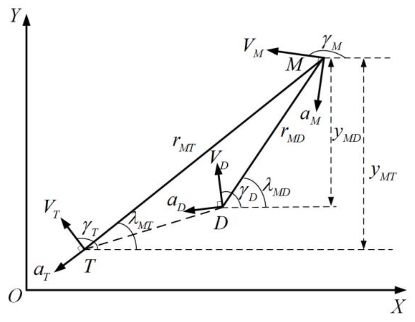
2.1. Nonlinear Engagement Kinematics

A schematic diagram for active defense engagement is shown in Figure 1, where T is the target aircraft, D is the defense missile (hereafter known as the defender), and M is the attacking missile (hereafter called the missile). The active defense engagement can be divided into two groups, namely, the missile-target (M-T) pursuit-evasion problem and the defender-missile (D-M) pursuit-evasion problem. ( x i , y i ) , i = ( T , D , M ) represent the position of the target, defender and missile, respectively; V i , a i and γ i , for i = ( T , D , M ) , respectively represent the velocity, acceleration, and heading angle of each flight vehicle, and the acceleration is perpendicular to the velocity; r M T and rMD are the M-T and D-M relative distances; λ M T and λMD are the LOS of M-T and D-M; y M T and y M D are the M-T and D-M relative distance along the Y-axis.
It is assumed that each flight vehicle has first-order dynamic characteristics, that is, the relationship between acceleration and guidance acceleration command is:
a ˙ i = u i a i τ i , i = ( T , D , M )
where, u i is the guidance acceleration command, and τ i is the time constant of the first-order dynamic characteristics. According to the geometric relation in Figure 1, the relative kinematic equations of D-M in active defense are:
{ r ˙ M D = V M cos ( γ M λ M D ) V D cos ( γ D λ M D ) λ ˙ M D = ( V M sin ( γ M λ M D ) V D sin ( γ D λ M D ) ) / r M D r ¨ M D = a M sin ( γ M λ M D ) + a D sin ( γ D λ M D ) + r M D λ ˙ M D 2 λ ¨ M D = ( a M cos ( γ M λ M D ) a D cos ( γ D λ M D ) 2 r ˙ M D λ ˙ M D ) / r M D a ˙ D = a D / τ D + u D / τ D γ ˙ D = a D / V D
Similarly, the relative kinematic equations of M-T in active defense are:
{ r ˙ M T = V M cos ( γ M λ M T ) V T cos ( γ T λ M T ) λ ˙ M T = ( V M sin ( γ M λ M T ) V T sin ( γ T λ M T ) ) / r M T r ¨ M T = a M sin ( γ M λ M T ) + a T sin ( γ T λ M T ) + r M T λ ˙ M T 2 λ ¨ M T = ( a M cos ( γ M λ M T ) a T cos ( γ T λ M T ) 2 r ˙ M T λ ˙ M T ) / r M T a ˙ T = a T / τ T + u T / τ T γ ˙ T = a T / V T

2.2. Linear Engagement Kinematics

It is assumed that both D-M and M-T engagement take place near the initial triangular collision area; that is, the values and variation range of the LOS angles are all small. Without loss of generality, the initial LOS of M-T engagement is taken as the X-axis, and the Y-axis is perpendicular to the X-axis. Based on this small-angle assumption, the kinematic model of active defense can be linearized along the initial LOS. a i N , i = ( T , D , M ) represent the acceleration components of each flight vehicle along the Y-axis, and obviously a i N = a i cos γ i . Take the state variable x = [ x M T T , x M D T ] , where x M T = [ y M T , y ˙ M T , a M , a T ] T and x M D = [ y M D , y ˙ M D , a D ] T .
Typical intercepting missile guidance laws include proportional guidance (PN), augmented proportional guidance (APN), and optimal guidance law (OGL), all of which can be expressed as a function of the navigation coefficient, zero-effort miss distance, and time-to-go [36]. After arrangement, they can be represented as follows:
u M N = K M T ( t g o M T ) x M T + K u ( t g o M T ) u T N
u M N = [ k 1 k 2 k M k T ] x M T + K u ( t g o M T ) u T N
where, t go M T is the estimated time-to-go for intercepting the target, and the other parameters can be obtained in an acceptable time by multi-model filtering or other methods [15,16]. In summary, the linear mathematical description of active defense is given as:
x ˙ = A ( t ) x + B ( t ) [ u T N       u D N ] T
where the expression of each matrix is:
A ( t ) = [ A 11 ( t ) A 12 ( t ) A 21 ( t ) A 22 ( t ) ] ,
A ( t ) = [ 0 1 0 0 0 0 0 0 0 1 1 0 0 0 k 1 τ M k 1 τ M k M 1 τ M k T τ M 0 0 0 0 0 0 1 / τ T 0 0 0 0 0 1 0 0 1 0 0 0 1 0 0 0 1 0 0 0 0 0 0 1 / τ D ] ,
B ( t ) = [ B 1 ( t ) B 2 ( t ) ]     = [ 0 0 0 0 k u / τ M 0 1 / τ T 0 0 0 0 0 0 1 / τ D ] T .

2.3. Timeline

Under the small-angle linearization hypothesis, the collision time t f and t f M T of D-M and M-T engagement can be approximately calculated as:
{ t f = r M D 0 V M 0 cos ( γ M 0 λ M D 0 ) V D 0 cos ( γ D 0 λ M D 0 ) t f M T = r M T 0 V M 0 cos ( γ M 0 λ M T 0 ) V T 0 cos ( γ T 0 λ M T 0 )
where, subscript 0 represents the initial moment. Based on this, the time-to-go tgo and t g o M T of D-M and M-T are respectively defined as:
{ t g o = t f t t g o M T = t f M T t
In successful active defense, the defender is requested to intercept the missile in advance. Therefore, t f < t f M T needs to be met.

2.4. Order Reduction and Zero-Effort Transformations

The physical meaning of ZEM and ZEV in D-M engagement is the terminal miss distance and the terminal velocity of the defender if, from the current moment t, the defender and target do not take any maneuvers and the missile still uses the previous guidance law to chase the target aircraft, which can be denoted by ZMD and ZvMD through terminal projection [7], where subscript MD refers to the missile and defender, as shown in Equation (9).
{ Z M D ( t ) = Λ M D Φ ( t f , t ) x ( t ) Z v M D ( t ) = Λ v M D Φ ( t f , t ) x ( t )
where, Λ M D = [ 0 1 × 4 1 0 1 × 2 ] and Λ v M D = [ 0 1 × 5 1 0 ] . Φ(tf, t) refers to the state transition matrix, as shown.
Φ ( t f , t ) = Φ ( t g o )   = [ ϕ 11 ϕ 12 ϕ 1 M ϕ 1 T ϕ 15 ϕ 16 ϕ 1 D ϕ 21 ϕ 22 ϕ 2 M ϕ 2 T ϕ 25 ϕ 26 ϕ 2 D ϕ 31 ϕ 32 ϕ 3 M ϕ 3 T ϕ 35 ϕ 36 ϕ 3 D ϕ 41 ϕ 42 ϕ 4 M ϕ 4 T ϕ 45 ϕ 46 ϕ 4 D ϕ 51 ϕ 52 ϕ 5 M ϕ 5 T ϕ 55 ϕ 56 ϕ 5 D ϕ 61 ϕ 62 ϕ 6 M ϕ 6 T ϕ 65 ϕ 66 ϕ 6 D ϕ 71 ϕ 72 ϕ 7 M ϕ 7 T ϕ 75 ϕ 76 ϕ 7 D ] ,
Φ ˙ ( t g o ) = Φ ( t f , t ) A ( t ) , Φ ( t f , t f ) = I 7 × 7 .
The solution of each element in the matrix can be found in [7]. Z M D and Z v M D can be calculated as:
{ Z M D = V λ M D t g o V λ M T ϕ 52 τ D 2 ψ ( t g o / τ D ) a D N + ϕ 5 M a M N + ϕ 5 T a T N Z v M D = V λ M D V λ M T ϕ 62 + τ D ξ ( t g o / τ D ) a D N + ϕ 6 M a M N + ϕ 6 T a T N
where, ψ ( μ ) = e u + μ 1 > 0               μ > 0 ,     ξ ( μ ) = e u 1 > 0               μ > 0 .
It can be seen that ZEM is the function of time-to-go, and is influenced by its estimate. However, it is very difficult to obtain the exact time-to-go in actual combat. Fortunately, as shown in [37,38], ZEV represents the sensitivity of the miss distance with respect to the time-to-go error and has a direct effect on the performance of the guidance strategy. Therefore, it is of great significance to make ZEV tend to zero as soon as possible in guidance law design.
Under the linearization model, there is a certain error in the calculation of target, defender, and missile acceleration components perpendicular to the LOS, which leads to an error in the modeling of the actual acceleration dynamic characteristics, namely:
a ˙ i N = u i N a i N τ i + δ a i N , i = { T , D , M }
where, Δ a i N , i = { T , D , M } are the total dynamics errors and are supposed to be bounded as:
| δ a i N | Δ a i N , i = { T , D , M }
where, Δ a i N , i = {T, D, M} are finite positive numbers.

3. Two-Way Cooperative SNTSM Guidance Design with TD

3.1. Principle and Stability Proof Smooth Nonsingular Terminal Sliding Mode

A second-order nonlinear system with uncertainties is considered as follows:
x ¨ = f ( x , t ) + g ( x , t ) u + d ( x , t )
where, [ x x ˙ ] T is the state vector, f ( x , t ) and g ( x , t ) are known functions, u is the control input, and d ( x , t ) is the bounded external disturbance satisfying | d ( x , t ) | d max , with a constant d max .
The SNTSM surface [30] is defined as:
s = x + a s i g τ ( x ˙ ) = x + a | x ˙ | τ s i g n ( x ˙ ) = 0
where, a > 0 , 1 < τ < 2 . If s = 0 is satisfied, x will converge to x = 0 in finite time.
Lemma: 
If the Lyapunov function V ( s ) = 1 2 s 2 satisfies the inequality:
V ˙ ( s ) + α V ( s ) + β V γ ( s ) 0
where, α , β > 0 , 0 < γ < 1 , s will converge to zero in finite time. The settling time can be expressed as:
T 1 α ( 1 γ ) ln α V 1 γ ( s 0 ) + β β
Theorem 1.
For the system shown in Equation (13), if the sliding mode in Equation (14) is adopted, the SNTSM law is expressed as:
u = [ f + a 1 τ 1 s i g 2 τ ( x ˙ ) + k 1 s + k 2 s i g μ ( s ) ] / g
where, k 1 > 0 , k 2 > 0 , 0 < μ < 1 , and the system state x can reach the sliding mode surface in finite time and then converge to zero in finite time.
Theorem 2.
Consider the Lyapunov function V 1 = 1 2 s 2 . Differentiating V 1 with respect to time and substituting Equations (14) and (17) into it yields:
V ˙ 1 = s s ˙ = a τ | x ˙ | τ 1 s [ k 1 s k 2 | s | μ sign ( s ) + d ]
Let k ¯ 1 = a τ | x ˙ | τ 1 k 1 , k ¯ 2 = a τ | x ˙ | τ 1 k 2 , d ¯ = a τ | x ˙ | τ 1 d . Equation (18) can be expressed as:
V ˙ 1 = k ¯ 1 s 2 k ¯ 2 | s | μ + 1 + s d ¯
Then, the above equation can be written in the following two forms:
V ˙ 1 + 2 ( k ¯ 1 d ¯ / s ) V 1 + 2 μ + 1 2 k ¯ 2 V 1 μ + 1 2 = 0
V ˙ 1 + 2 k ¯ 1 V 1 + 2 μ + 1 2 ( k ¯ 2 d ¯ s μ + 1 s i g n ( s ) ) V 1 μ + 1 2 = 0
When synthesizing the previous analysis, the finite time convergent region can be given as: | s | Λ = min { d max k 1 , ( d max k 2 ) 1 / μ } . Furthermore, the state x will converge to the region | x | 2 Λ in finite time. Therefore, Theorem 1 has been proved completely.

3.2. Two-Way Cooperative SNTSM Guidance Design

In two-way cooperative engagement, SNTSM is used to design guidance laws and reduce the sensitivity to time-to-go on the premise that the defender and the aircraft know one another’s states. At this point, the system has two control outputs, u T and u D , to be designed. The sliding vector s can be defined using two switching variables, s 1 and s 2 , as:
s = [ s 1 s 2 ] = [ e 1 + a 1 s i g τ ( e ˙ 1 ) e 2 + a 2 s i g τ ( e ˙ 2 ) ] T
where, e = [ e 1 e 2 ] T , e 1 = 0 t [ Z M D c ( τ ) Z M D ( τ ) ] d τ , e 2 = 0 t [ Z v M D c ( τ ) Z v M D ( τ ) ] d τ , e ˙ 1 = Z M D c Z M D , e ˙ 2 = Z v M D c Z v M D .
The derivatives of Z M D and Z vM D are calculated as follows:
Z ˙ M D = V ˙ λ M D t g o τ D 2 ψ ( t g o / τ D ) a ˙ D N V ˙ λ M T ϕ 52 + ϕ 5 M a ˙ M N + ϕ 5 T a ˙ T N                                                   + t ˙ g o ( V λ M D τ D 2 ψ ( t g o / τ D ) a D N V λ M T ϕ 52 + ϕ 5 M a M N + ϕ 5 T a T N )
Z ˙ v M D = V ˙ λ M D V ˙ λ M T ϕ 62 + τ D ξ ( t g o / τ D ) a ˙ D N + ϕ 6 M a ˙ M N +   ϕ 6 T a ˙ T N                                                       + t ˙ g o ( V λ M T ϕ 52 exp ( t g o / τ D ) a D N + ϕ 6 M a M N + ϕ 6 T a T N )
The second derivative of e 1 and e 2 is:
e ¨ = [ e ¨ 1 e ¨ 2 ] = [ Z ˙ M D c Z ˙ M D Z ˙ v M D c Z ˙ v M D ]
and can be written as:
e ¨ = F + Gu + δ       = [ F 1 F 2 ] + [ G 11 G 12 G 21 G 22 ] [ u T N u D N ] + [ δ Z M D δ Z v M D ]
where,
F 1 = Z ˙ M D c r M D V ˙ r M D V r M D 2 [ V λ M D a D N τ D { 1 - exp ( t g o τ D ) } ϕ 52 ( a M N a T N ) + a M N t g o ( ϕ 5 M τ M a M N + ϕ 5 T τ T a T N ) + V r M T λ ˙ M T + ϕ 5 M ( K 2 V λ M T + K M a M N + K T a T N ) τ M ] ,
F 2 = Z ˙ v M D c r M D V ˙ r M D V r M D 2 [ a D N exp ( t g o τ D ) ϕ 62 ( a M N a T N ) + a M N ( ϕ 6 M τ M a M N + ϕ 6 T τ T a T N ) + V r M T λ ˙ M T ϕ 62 + ϕ 6 M ( K 2 V λ M T + K M a M N + K T a T N ) τ M V r M D λ ˙ M D ] ,
G 11 = ϕ 5 T / τ T , G 12 = τ D ψ ( t g o / τ D ) , G 21 = ϕ 6 T / τ T , G 22 = ξ ( t g o / τ D ) ,
δ Z M D = τ D 2 ψ ( t g o / τ D ) δ a D N ϕ 5 M δ a M N ϕ 5 T δ a T N , δ Z v M D = τ D ξ ( t g o / τ D ) δ a D N ϕ 6 M δ a M N ϕ 6 T δ a T N .
Through Equation (12), we can attain that | δ Z M D | and | δ Z v M D | are bounded by finite positive numbers Δ Z M D and Δ Z v M D , namely:
| δ Z M D | Δ Z M D , | δ Z v M D | Δ Z v M D
According to Equation (17), we have:
[ u T N u D N ] = G 1 [ F + a - 1 τ - 1 s i g 2 I τ ( e ˙ ) + Ks + l s i g μ ( s ) ]
where, a = d i a g ( a 1 , a 2 ) , τ = d i a g ( τ 1 , τ 2 ) , K = d i a g ( k 1 , k 2 ) , l = d i a g ( l 1 , l 2 ) , μ = d i a g ( μ 1 , μ 2 ) , a i > 0 ,       1 < τ i < 2 , k i > 0 , l i > 0 , 0 < μ i < 1 ( i = 1 , 2 ) . The actual commands for the target and the defender can be given as:
u = [ u T u D ] T = [ u T N cos ( γ T λ M T ) u D N cos ( γ D λ M D ) ]

3.3. Tracking Differentiator

In the control system here, the error is directly taken as:
e = v y
where, v is the set input value and y is the system output. The selection method of this error makes a large initial error; that is, the error definition of Equation (22) is the main cause of overload saturation. The TD is adopted for arranging the transition process, and the smooth reference input signal is obtained. Moreover, the differential signal of the set input value is extracted. The contradiction between rapidity and overshoot can be solved by selecting reasonable parameters, and the system can obtain strong robustness. The synthesis function of the time-optimal control system for the discrete second-order system with TD [39] is as follows:
{ ν 1 ( k + 1 ) = ν 1 ( k ) + h ν 2 ( k ) ν 2 ( k + 1 ) = ν 2 ( k ) + h u u = f h a n ( ν 1 ( k ) - ν 0 ( k ) , ν 2 ( k ) , r , h )
f h a n ( x 1 , x 2 , r , h )     = { d = r h d 0 = h d y = x 1 + h x 2 a 0 = d 2 + 8 r | y | a = { x 2 + ( a 0 d ) 2 s i g n ( y ) , | y | > d 0 x 2 + y h , | y | d 0   f h a n = { r s i g n ( a ) , | a | > d r a d , | a | d  
where, h is the sampling period, and r is the quickness factor, and they are all mutable parameters. Signal v 1 is the transition value of input signal v 0 through the differential tracker, and v 2 is the differential signal of v 1 . By using DT, the system changes the original fixed reference instruction into a smooth instruction signal that reaches the specified value after a finite time.

4. One-Way Cooperative Smooth Nonsingular Terminal Sliding Guidance Design

In practice, there is a situation where the target does not rely on the defender to carry out the one-on-one engagement strategy, such as the bang–bang maneuver, random maneuver, or optimal maneuver strategy. At this point, the target does not need any information on the defender, which constitutes a one-way cooperative guidance problem. If the target aircraft adopts a certain maneuver strategy u T N ( t ) , the ZEM and ZEV can be presented as:
{ Z M D O C ( t ) = Z M D ( t ) + Ξ M D   Z v M D O C ( t ) = Z v M D ( t ) + Ξ v M D
where, Ξ M D = Λ M D t t f M D Φ ( t f M D , t ) B T u T N ( τ ) d τ , Ξ v M D = Λ v M D t t f M D Φ ( t f M D , t ) B T u T N ( τ ) d τ , and we can attain
Z ˙ M D O C = Z ˙ M D ( ϕ 5 T / τ T ) u T N
The switching variable is defined as:
s 3 = e 3 + a 3 s i g τ ( e ˙ 3 )
where, e 3 = 0 t [ Z M D c ( τ ) Z M D O C ( τ ) ] d τ , e ˙ 3 = Z M D c Z M D O C . Then, e ¨ 3 can be given as:
e ¨ 3 = Z ˙ M D c Z ˙ M D O C = F 1 + g 3 u D N + δ Z M D O C
where, g 3 = τ D ψ ( t g o / τ D ) , δ Z M D O C = δ Z M D + ( ϕ 5 T / τ T ) u T N . If the target maneuver is not available, u T N in δ Z M D O C can be considered as a bounded uncertainty. In addition, it can be obtained from Equation (27) that | δ Z M D O C | is bounded by a positive number. The guidance command for the defender in this case can be obtained as:
u D = F 1 + a 3 1 τ 3 1 s i g 2 τ 3 ( e 3 ) + k 3 s 3 + l 3 s i g 2 μ 3 ( s 3 ) g 3 cos ( γ D λ M D )
where, a 3 > 0 , 1 < τ 3 < 2 , 0 < μ 3 < 1 , k 3 > 0 , l 3 > 0 .

5. Simulation Study

The simulation conditions are set as follows: V T = 200 m/s, V M = V D = 300 m/s, τ M = τ D = τ T = 0.1 s. The proportional navigation guidance coefficient of the defender is N P N M = 3 . The maximum available overloads of the defender, the target, and the missile are a D max = a T max = 10 g, a M max = 30 g, respectively. The simulation step size is 1 ms. The initial position of defender and target is (0 km, 0 km), and the initial position of the missile is (0 km, 5 km). The proposed guidance algorithm is tested under γ T 0 = 0 , γ D 0 = 10 ° , and γ M 0 = 150 ° . The blind zone of the seeker is r b = 100 m, and the blind zone guidance strategy selected here is that the missile guidance instruction remains unchanged after the seeker enters the blind zone. Some of the elements in the transfer matrix used to calculate ZEM and ZEV with respect to t g o , are shown in Figure 2, and the other necessary elements are ϕ 55 ( t g o ) = 1 ,       ϕ 56 ( t g o ) = t g o , ϕ 65 ( t g o ) = 0 ,       ϕ 66 ( t g o ) = 1 . It can be observed that ϕ 5 M and ϕ 6 M are smaller overall than ( ϕ 5 D , ϕ 5 T ) and ( ϕ 6 D , ϕ 6 T ) , respectively, which allows a small gain to counter even high initial heading errors of the missile. Note that all elements in Figure 2 except ϕ 6 M do not change sign during the engagement. Moreover, unlike the other elements, ϕ 61 and ϕ 6 M are not monotonic, which means the peak doesn’t always occur at the beginning of the engagement.

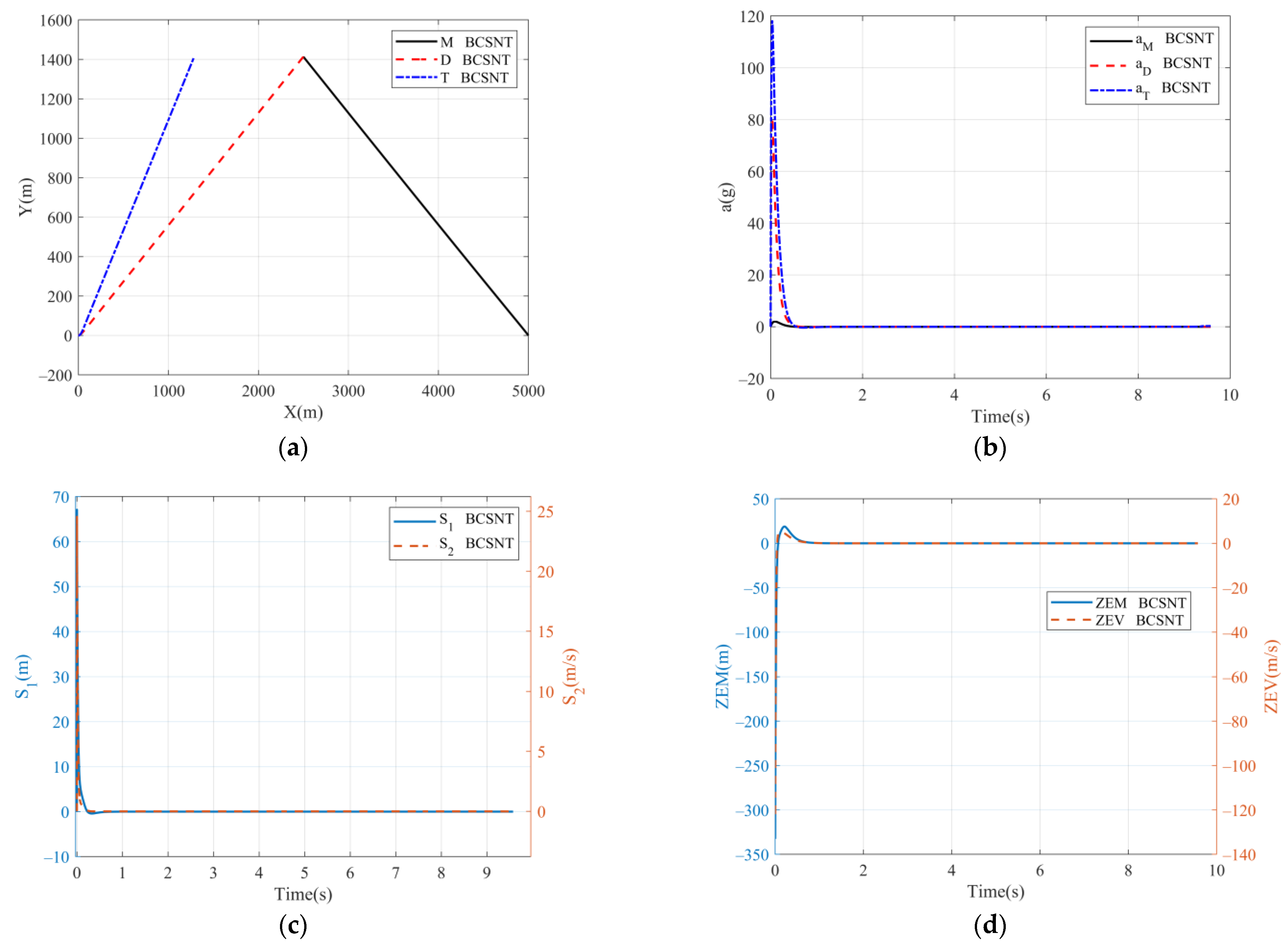
5.1. Two-Way Cooperative SNTSM Guidance without a TD

In this section, the guidance strategy given by Equation (29) is denoted by the label “BCSNT.” Parameters in Equation (28) are set as follows: a 1 = a 2 = 0.2 , τ 1 = τ 2 = 1.001 , μ 1 = μ 2 = 0.6 , k 1 = 250 , k 2 = 200 , l 1 = 70 , and l 2 = 50 . In order to truly reflect the performance of the BCSNT algorithm, the overload limits for three players are not considered here. The trajectory, overload, switching surfaces, ZEM, and ZEV are shown in Figure 3. The miss distance is 0.02 m. As can be seen from Figure 3c, the BCSNT algorithm reaches the switching surfaces in a very short time; thus, the ZEM and ZEV approach zero quickly. In addition, the trajectory curves are nearly straight lines, but the overload requirement is too large to be realized. When considering the overload limits, the defender will not hit the target. Therefore, the BCSNT algorithm alone can solve the problem of fast convergence, but it will cause too large of an overload instruction in the initial stage. Therefore, it is necessary to introduce a TD to arrange the instruction transition process.

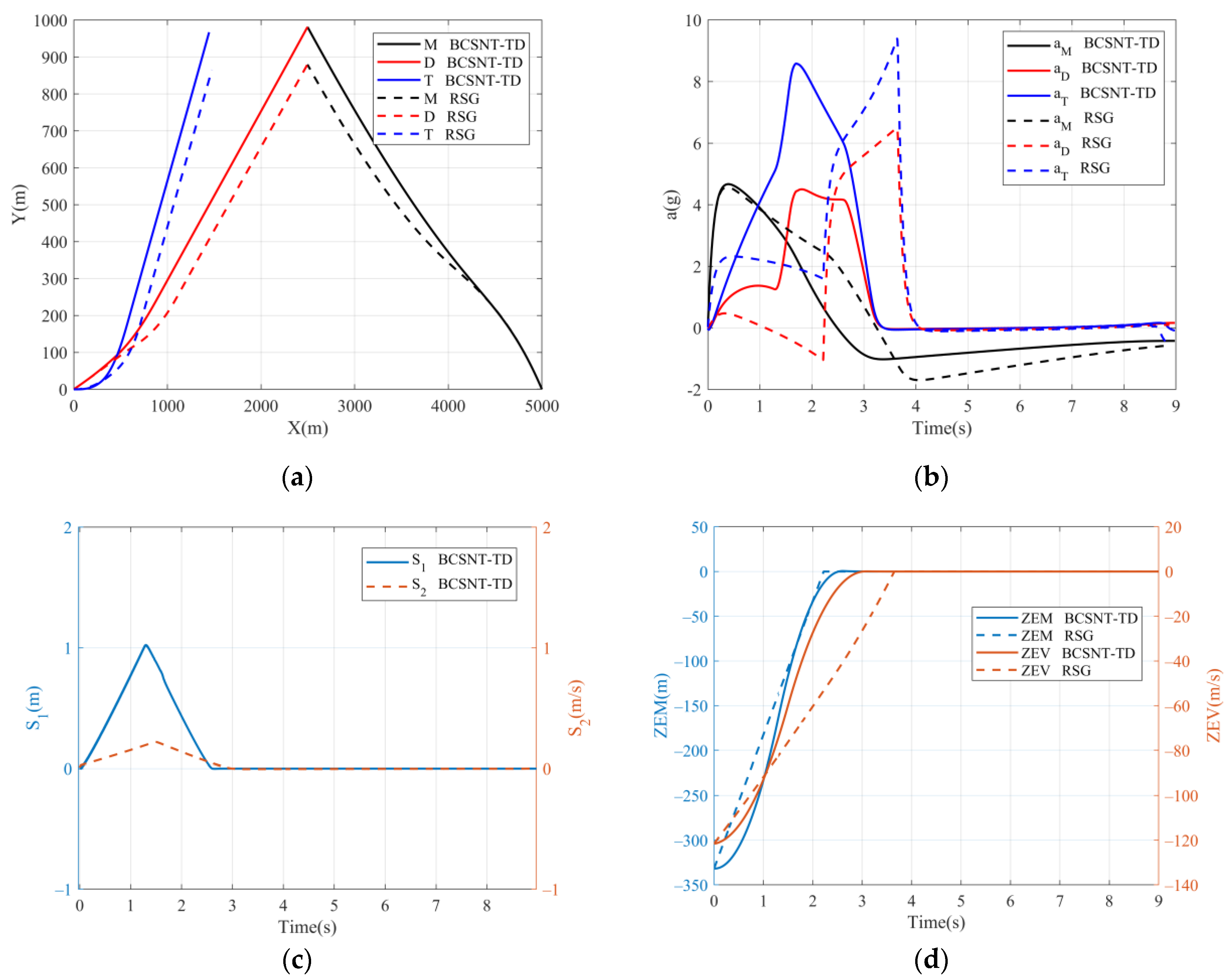
5.2. Comparation for Two-Way Cooperative SNTSM Guidance with TD and Reduced-Sensitivity Guidance

In this section, the two-way cooperative SNTSM guidance with a TD given by Equations (29) and (31) is denoted by the label “BCSNT-TD.” The other parameters are set as per the previous subsection. The quickness factors and sampling period of the TD for e ˙ 1 and e ˙ 2 are r e ˙ 1 = 200 , r e ˙ 2 = 50 , and h e ˙ 1 = h e ˙ 2 = 20 ms, respectively. As a comparison, the guidance strategy derived in [18] is represented by reduced sensitivity guidance (RSG), whose guidance strategy is:
{ [ u T N u D N ] = G 1 [ F + M 1 s i g n ( s ) ] u = [ u T N cos ( γ T λ M T ) u D N cos ( γ D λ M D ) ]
where, M 1 = d i a g ( 150 , 40 ) , and the details about Equation (38) can be found in [18]. The discontinuous function sign(s) for the RSG is approximated by the sigmoid function:
s g m f ( s ) = 2 ( 1 1 + exp ε s 1 2 ) ,   ε > 0
where, the constant ε is chosen as 8.
The trajectories, overloads, switching surfaces, ZEM, and ZEV for the BCSNT-TD and RSG are shown in Figure 4. As presented in Figure 4b, the maximum overload value of the BCSNT-TD is smaller than that of the RSG, and the occurrence time for maximum overload is earlier than for the RSG. As the energy of the aircraft gradually attenuates in the passive section (without the thrust of engines), the maximum available overload it can also provide gradually decreases, so the earlier demand for large overload conforms to the principle of energy management, which makes full use of the large maneuverability in the early stages of the engagement. The miss distances of the BCSNT-TD and RSG are 0.022 m and 0.165 m, respectively. When combining Figure 4c,d, it can be seen that the BCSNT-TD reaches the sliding mode surface faster than the RSG.
The sensitivity of guidance to the t g o estimates are evaluated by additive bias. To do so, bias errors ranging from 0 to 1 s with 0.1 s interval are introduced in the t g o estimate. The mean, standard deviation, and root mean square (RMS) values of the miss distance for the BCSNT-TD and RSG are calculated, as shown in Table 1. We can observe that the statistical values are small and have negligible variations with respect to t g o errors. The statistical values of the BCSNT-TD are all smaller than those of the RSG. The BCSNT maximizes the use of the overload capacity and has high steady-state accuracy, which can be adopted in engineering practice with the introduction of a TD. BCSNT-TD is of high guidance precision, meets the overload constraint, and has stronger practicality and robustness.

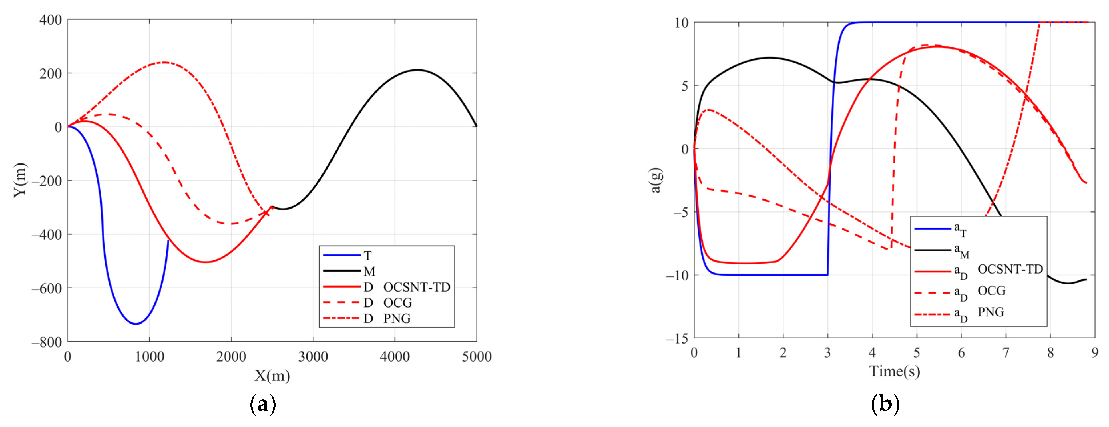
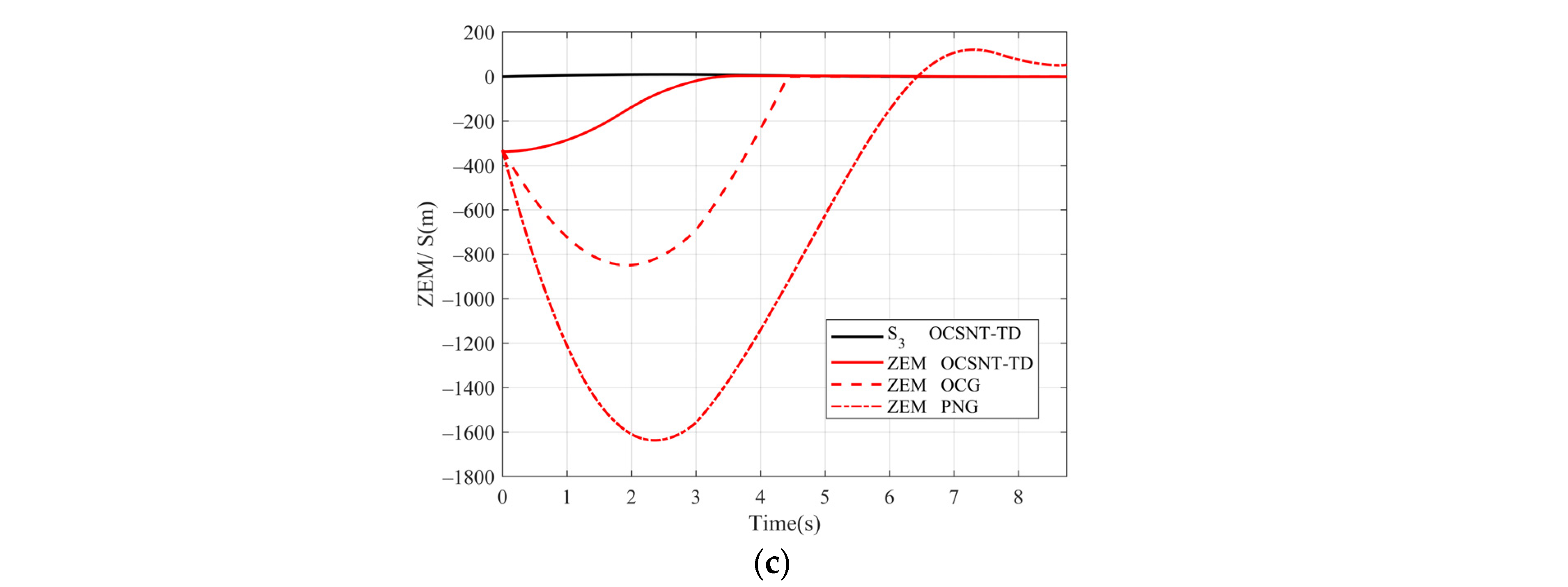
5.3. Comparation for One-Way Cooperative SNTSM Guidance with a TD, One-Way Cooperative Guidance, and Proportional Navigation Guidance (PNG)

In this case, the guidance of the target does not depend on the state of the defender. It is assumed that the target implements a nonlinear bang–bang maneuver, and the switching time is set to 3 s. In this subsection, one-way cooperative smooth nonsingular terminal sliding mode guidance with a TD given by Equations (37) and (31) is denoted by the label “OCSNT-TD.” The other parameters are set as per the first subsection. a 3 = 0.009 , τ 3 = 1.001 , μ 3 = 0.6 , k 3 = 1 0 , l 3 = 10 . By contrast, the one-way cooperative guidance strategy derived in [18] is:
u D = u D N cos ( γ D λ M D ) = F + M 2 s i g n ( S ) τ D ψ ( t g o / τ D ) cos ( γ D λ M D )
The PNG guidance strategy can be expressed as:
u D = u D N cos ( γ D λ M D ) = y M D N P N D / t g o 2 + y ˙ M D N P N D / t g o cos ( γ D λ M D )
Figure 5 shows the trajectories of a three-flight vehicle under the OCSNT-TD, OCG, and PNG algorithms. It can be found that the OCSNT-TD and OCG guidance algorithms can accurately hit the interceptor missile, and the final miss distance is 0.09 m and 0.18 m, respectively. PNG typically eliminates the rotation of LOS, but due to maneuverability limitations, it can be found from Figure 5b that the defender is always in an overload saturation state in the terminal phase; as a result, the final miss distance is 44.9 m. It can be observed that the guidance accuracy of the OCSNT-TD is better than that of OCG, while PNG fails. The ZEM of the OCSNT-TD converges to zero faster than that of the other two guidance algorithms, as shown in Figure 5.

6. Conclusions and Future Discussion

In this paper, we investigate the three-body engagement problem when an aerial target or its friendly platform launches an active defense missile to intercept an attacking missile, and we propose two-way and one-way cooperative guidance laws for a defense missile based on smooth nonsingular terminal sliding mode with a tracking differentiator. The proposed algorithm is deduced in linear engagement kinematics, and its stability is proven while the algorithm is applied successfully in a nonlinear engagement frame.
In the process of designing the algorithm, the zero-effort miss distance and zero-effort velocity, as well as their integral values, are chosen to design the smooth nonsingular terminal sliding mode surface with finite-time convergence, which guarantees a sufficiently small miss distance and reduces the sensitivity to time-to-go. Meanwhile, the applicability of the algorithm is enhanced by the transition process arranged by the tracking differentiator.
The performance of the proposed algorithm is verified by numerical simulations. Compared to existing methods, the simulation results show that the proposed algorithm has a shorter convergence time for the same maximum overload, higher accuracy, less sensitivity to time-to-go, more reasonable overload distribution, and stronger robustness, which can be used under the situation of the maneuvering capability of the defense missile and when the target is limited. It is easy to see that the method proposed in this paper requires no additional information compared to the existing methods, and the numerical computation is only slightly increased.
The exploration of anti-windup techniques, which make the target and the defend missile meet their respective overload limits for more flexible parameter settings, and cooperative guidance laws for imposing a relative intercept angle or applying to the three-dimensional plane are possible future directions of research.

Author Contributions

Conceptualization, all authors (Q.L., Y.F., T.Y., X.L., J.Y.); methodology, Q.L. and Y.F.; software, Q.L. and T.Y.; writing—original draft preparation, Q.L. and T.Y.; writing—review and editing, Q.L. and T.Y.; validation, T.Y.; investigation, X.L. All authors have read and agreed to the published version of the manuscript.

Funding

This research received no external funding.

Institutional Review Board Statement

Not applicable.

Informed Consent Statement

Not applicable.

Data Availability Statement

All data used during the study appear in the submitted article.

Conflicts of Interest

All of the authors declare that they have no known competing financial interests or personal relationships that could appear to influence the work reported in this paper.

References

  1. Yamasaki, T.; Takano, H. Modified command to line-of-sight intercept guidance for aircraft defense. J. Guid. Control Dyn. 2013, 36, 898–902. [Google Scholar] [CrossRef]
  2. Ratnoo, A.; Shima, T. Line-of-sight interceptor guidance for defending an aircraft. J. Guid. Control Dyn. 2013, 34, 522–532. [Google Scholar] [CrossRef]
  3. Ratnoo, A.; Shima, T. Guidance strategies against defended aerial targets. J. Guid. Control Dyn. 2013, 35, 1059–1068. [Google Scholar] [CrossRef]
  4. Kumar, S.R.; Mukherjee, D. Cooperative active aircraft protection guidance using line-of-sight approach. IEEE Trans. Aerosp. Electron. Syst. 2021, 57, 957–967. [Google Scholar] [CrossRef]
  5. Prokopov, O.; Shima, T. Linear quadratic optimal cooperative strategies for active aircraft protection. J. Guid. Control Dyn. 2013, 36, 753–764. [Google Scholar] [CrossRef]
  6. Garcia, E.; Casbeer, D.W.; Pachter, M. Cooperative strategies for optimal aircraft defense from an attacking missile. J. Guid. Control Dyn. 2015, 38, 1510–1520. [Google Scholar] [CrossRef]
  7. Shima, T. Optimal cooperative pursuit and evasion strategies against a homing missile. J. Guid. Control Dyn. 2011, 34, 414–425. [Google Scholar] [CrossRef]
  8. Weiss, M.; Shima, T. Minimum effort pursuit/evasion guidance with specified miss distance. J. Guid. Control Dyn. 2016, 39, 1069–1079. [Google Scholar] [CrossRef]
  9. Fang, F.; Cai, Y. Optimal cooperative guidance with guaranteed miss distance in three-body engagement. P. I. Mech. Eng. G-J. Aer. 2018, 232, 492–504. [Google Scholar] [CrossRef]
  10. Weiss, M.; Shima, T.; Castaneda, D.; Rusnak, I. Combined and cooperative minimum-effort guidance algorithms in an active aircraft defense scenario. J. Guid. Control Dyn. 2017, 40, 1241–1254. [Google Scholar] [CrossRef]
  11. Garcia, E.; Casbeer, D.W.; Pachter, M. Active target defense using first order missile models. Automatica 2017, 78, 139–143. [Google Scholar] [CrossRef]
  12. Perelman, A.; Shima, T. Cooperative differential games strategies for active aircraft protection from a homing missile. J. Guid. Control Dyn. 2011, 34, 761–773. [Google Scholar] [CrossRef]
  13. Saurav, A.; Kumar, S.R.; Maity, A. Cooperative guidance strategies for aircraft defense with impact angle constraints. In AIAA SciTech Forum, 7–11 January 2019; Online: San Diego, CA. USA.
  14. Rubinsky, S.; Gutman, S. Three-player pursuit and evasion conflict. J. Guid. Control Dyn. 2014, 37, 98–110. [Google Scholar] [CrossRef]
  15. Shaferman, V.; Shima, T. Cooperative multiple model adaptive guidance for an aircraft defending missile. J. Guid. Control Dyn. 2010, 33, 1801–1813. [Google Scholar] [CrossRef]
  16. Fang, F.; Cai, Y.; Yu, Z. Adaptive estimation and cooperative guidance for active aircraft defense in stochastic scenario. Sensors 2019, 19, 979. [Google Scholar] [CrossRef] [PubMed] [Green Version]
  17. Liu, S.; Yan, B.; Zhang, X.; Liu, W.; Yan, J. Fractional-order sliding mode guidance law for intercepting hypersonic vehicles. Aerospace 2022, 9, 53. [Google Scholar] [CrossRef]
  18. Kumar, S.R.; Shima, T. Cooperative nonlinear guidance strategies for aircraft defense. J. Guid. Control Dyn. 2017, 40, 124–138. [Google Scholar] [CrossRef]
  19. Ates, H.U. Lyapunov based nonlinear impact angle guidance law for stationary targets. In AIAA Guidance, Navigation, and Control Conference, 5–9 January 2015; Online: Kissimmee, FL, USA.
  20. Zhang, Y.; Jiao, G.; Sun, M.; Chen, Z. Finite Time Convergent Guidance Law with Impact Angle Constraint Based on Sliding Control. In Proceedings of the 30th Chinese Control Conference, Yantai, China, 22–24 July 2011; pp. 2597–2601. [Google Scholar]
  21. He, S.; Lin, D. Adaptive nonsingular sliding mode based guidance law with terminal angular constraint. Int. J. Aeronaut. Space 2014, 15, 146–152. [Google Scholar] [CrossRef] [Green Version]
  22. Feng, Y.; Yu, X.; Han, F. On nonsingular terminal sliding-mode control of nonlinear systems. Automatica 2013, 49, 1715–1722. [Google Scholar] [CrossRef]
  23. Yu, S.; Yu, X.; Shirinzadeh, B.; Man, Z. Continuous finite-time control for robotic manipulators with terminal sliding mode. Automatica 2005, 41, 1957–1964. [Google Scholar] [CrossRef]
  24. Khoo, S.; Xie, L.; Man, Z. Robust finite-time consensus tracking algorithm for multirobot systems. IEEE-ASME T. Mech. 2009, 14, 219–228. [Google Scholar] [CrossRef]
  25. Kumar, S.R.; Rao, S.; Ghose, D. Nonsingular terminal sliding mode guidance with impact angle constraints. J. Guid. Control Dyn. 2014, 37, 1–17. [Google Scholar] [CrossRef]
  26. Wang, X.; Wang, J. Partial integrated missile guidance and control with finite time convergence. J. Guid. Control Dyn. 2013, 36, 1399–1409. [Google Scholar] [CrossRef]
  27. Yang, S.; Zhang, K.; Chen, P. Adaptive terminal sliding mode guidance law with impact angle constraint. J. Beijing Univ. Aeronaut. Astronaut. 2016, 42, 1566–1574. [Google Scholar]
  28. Song, J.; Song, S.; Zhou, H. Adaptive nonsingular fast terminal sliding mode guidance law with impact angle constraints. Int. J. Control Autom. 2016, 14, 99–114. [Google Scholar] [CrossRef]
  29. Zou, X.; Zhou, D.; Du, R.; Liu, J. Adaptive nonsingular terminal sliding mode cooperative guidance law in active defense scenario. P. I. Mech. Eng. G-J. Aer. 2015, 230, 307–320. [Google Scholar] [CrossRef]
  30. Zhou, J.; Yang, J. Smooth sliding mode control for missile interception with finite-time convergence. J. Guid. Control Dyn. 2015, 38, 1311–1318. [Google Scholar] [CrossRef]
  31. Zhang, Z.; Xu, H.; Zou, J.; Zheng, G. Tracking differentiator-based dynamic surface control for the power control of the wind generation system in the wind farm. P. I. Mech. Eng. G-J. Aer. 2013, 227, 275–285. [Google Scholar] [CrossRef]
  32. Zhang, H.; Xie, Y.; Long, Z. Fault detection based on tracking differentiator applied on the suspension system of maglev train. Math. Probl. Eng. 2015, 2015, 1–9. [Google Scholar] [CrossRef] [Green Version]
  33. Lou, W.; Zhu, M.; Guo, X. Spatial trajectory tracking control for unmanned airships based on active disturbance rejection control. P. I. Mech. Eng. G-J. Aer. 2019, 233, 2231–2240. [Google Scholar] [CrossRef]
  34. Yan, M.; Xue, C.; Xie, X. A novel model free adaptive controller with tracking differentiator. In Proceedings of the 2009 IEEE International Conference on Mechatronics and Automation, Changchun, China, 9–12 August 2009; pp. 4191–4196. [Google Scholar]
  35. Wang, Z.; Long, Z.; Xie, Y.; Ding, J.; Luo, J.; Li, X. A discrete nonlinear tracking-differentiator and its application in vibration suppression of maglev system. Math. Probl. Eng. 2020, 2020, 1–9. [Google Scholar] [CrossRef]
  36. Zarchan, P. Tactical and Strategic Missile Guidance, 7th ed.; American Institute of Aeronautics and Astronautics: Reston, VA, USA, 2019. [Google Scholar]
  37. Ben-Asher, J.Z. Linear quadratic pursuit-evasion games with terminal velocity constraints. J. Guid. Control Dyn. 1996, 19, 499–501. [Google Scholar] [CrossRef]
  38. Ben-Asher, J.Z.; Yaesh, I. Optimal guidance with reduced sensitivity to time-to-go estimation errors. J. Guid. Control Dyn. 1997, 20, 158–163. [Google Scholar] [CrossRef]
  39. Xie, Y.; Long, Z.; Li, J.; Zhang, K.; Luo, K. Research on a new nonlinear discrete-time tracking-differentiator filtering characteristic. In Proceedings of the 7th World Congress on Intelligent Control and Automation, Chongqing, China, 25–27 June 2008; pp. 6750–6755. [Google Scholar]
Figure 1. Active defense engagement.
Aerospace 09 00221 g001
Figure 2. Transition matrix elements.
Aerospace 09 00221 g002
Figure 3. Simulation results of the BCSNT. (a) Trajectories; (b) variation curves of the overload; (c) variation curves of the switching surface; (d) variation curves of the ZEM and ZEV.
Aerospace 09 00221 g003
Figure 4. Simulation results of the BCSNT-TD and RSG. (a) Trajectories; (b) variation curves of the overload; (c) variation curves of the switching surface; (d) variation curves of the ZEM and ZEV.
Aerospace 09 00221 g004
Figure 5. Simulation results of the OCSNT-TD, OCG and PNG. (a) Trajectories; (b) variation curves of the overload; (c) variation curves of the ZEM and switching surfaces.
Aerospace 09 00221 g005aAerospace 09 00221 g005b
Table 1. Statistic values for the BCSNT-TD and RSG.
Guidance AlgorithmBCSNT-TDRSG
Mean0.44010.6360
Standard deviation0.35610.4909
RMS0.55590.7897
Publisher’s Note: MDPI stays neutral with regard to jurisdictional claims in published maps and institutional affiliations.

