1. Introduction
The aspect ratio is a key factor for the induced drag of a wing. To increase flight efficiency, high-altitude long-endurance aircraft are often designed with large aspect ratios [
1]. However, when the wing area is the same, a large aspect ratio also means a large wingspan. For instance, the RQ-4A “Global Hawk” has a wingspan of 35.4 m and an aspect ratio of 25, while the two parameters of the U-2R reconnaissance aircraft are 31.4 m and 17, respectively. The span of such a ten-ton class high-altitude long-endurance UAV, the RQ-4A “Global Hawk”, is close to that of a Boeing 737, which is approximately 70 tons. It would be difficult for an aircraft with such a large span to meet the takeoff/landing restrictions of small airports or aircraft carriers. The operation and maintenance of these aircraft will be troublesome at small airports. In addition, the long and thin geometry will bring great difficulty to the strength and stiffness of the wing. The poor ability to resist gusts and crosswinds at low speed is also the main disadvantage.
Morphing aircraft have gradually become a hot spot of interest for aircraft design [
2,
3,
4,
5,
6,
7] in recent years. Morphing technology is expected to change the wingspan at different flight stages of an aircraft, which can effectively solve the design contradiction between the takeoff/landing and cruise performance of a large aspect ratio aircraft.
In the early years, variable wingspan was usually realized by a variable-sweep wing or a folding wingtip such as the F-111 [
8] and XB-70 [
9]. Along with the progress in control, materials, and other disciplines, the morphing of aircraft has gradually diversified. Lockheed Martin developed a Z-shaped folding wing morphing aircraft for the US military [
10,
11], which is driven by an electric actuator. Lesieutre et al. [
12] designed a morphing wing that uses a flexible truss to change the length. Kheong et al. [
13,
14] proposed a morphing scheme using inflatable wings to change the length of the aircraft. Ajanic et al. [
15] developed a bird-like morphing aircraft that can change the length of the wings and tail at the same time. Folding wingtips were first used on the Boeing 777X as a measure to reduce the wingspan on the ground when taxiing or parking. However, if morphing can be realized in flight, it is expected to not only reduce the aircraft’s takeoff/landing wingspan but also improve the aircraft’s roll stability and gust resistance in the future [
16,
17].
For morphing aircraft, a comparison of morphing benefits and penalties is critical and necessary. The advantage of morphing aircraft is that the aerodynamic geometry can be changed to meet the flight’s requirements under different conditions or to improve the flight performance of the aircraft under different flight conditions. The problems caused by morphing mainly include the increase in the weight of the aircraft’s structure, the reduction in the effective volume of the aircraft, the change in the center of weight, the aerodynamic moment, and the reliability of the mechanism. It is hoped that the morphing device can be simplified as much as possible. If the benefits of morphing technology cannot exceed the penalties it brings, it will not have value for application.
Taking into consideration the above challenges, we propose the concept of a new mono-biplane morphing aerodynamics-driven aircraft [
18]. With morphing, the aircraft can have a biplane configuration with a short span during takeoff and landing. It can also have a large aspect monoplane wing configuration for cruising. The morphing process is conducted in flight. It uses aerodynamics to complete the morphing autonomously without any additional driving mechanism. The ability to change the wingspan reaches nearly 50% of the wing. The effective lift area of the wing is almost unchanged, the mechanism of the morphing is relatively simple, and the internal space of the wing is only slightly occupied. This type of morphing can effectively avoid the defects of other variable wingspan methods.
This paper introduces a mono-biplane aerodynamics-driven morphing aircraft as a new concept and discusses the idea, design rule, and advantages of this morphing in detail. The wing model was built, and the principle and feasibility of aerodynamics-driven morphing were verified through ground vehicle tests. Multidisciplinary comprehensive analysis was used to study the improvement in cruise performance brought by the mono-biplane aerodynamics-driven morphing aircraft. The range of benefits compared to the traditional configuration aircraft were evaluated.
2. The Concept of a Mono-Biplane Aerodynamics-Driven Morphing Aircraft
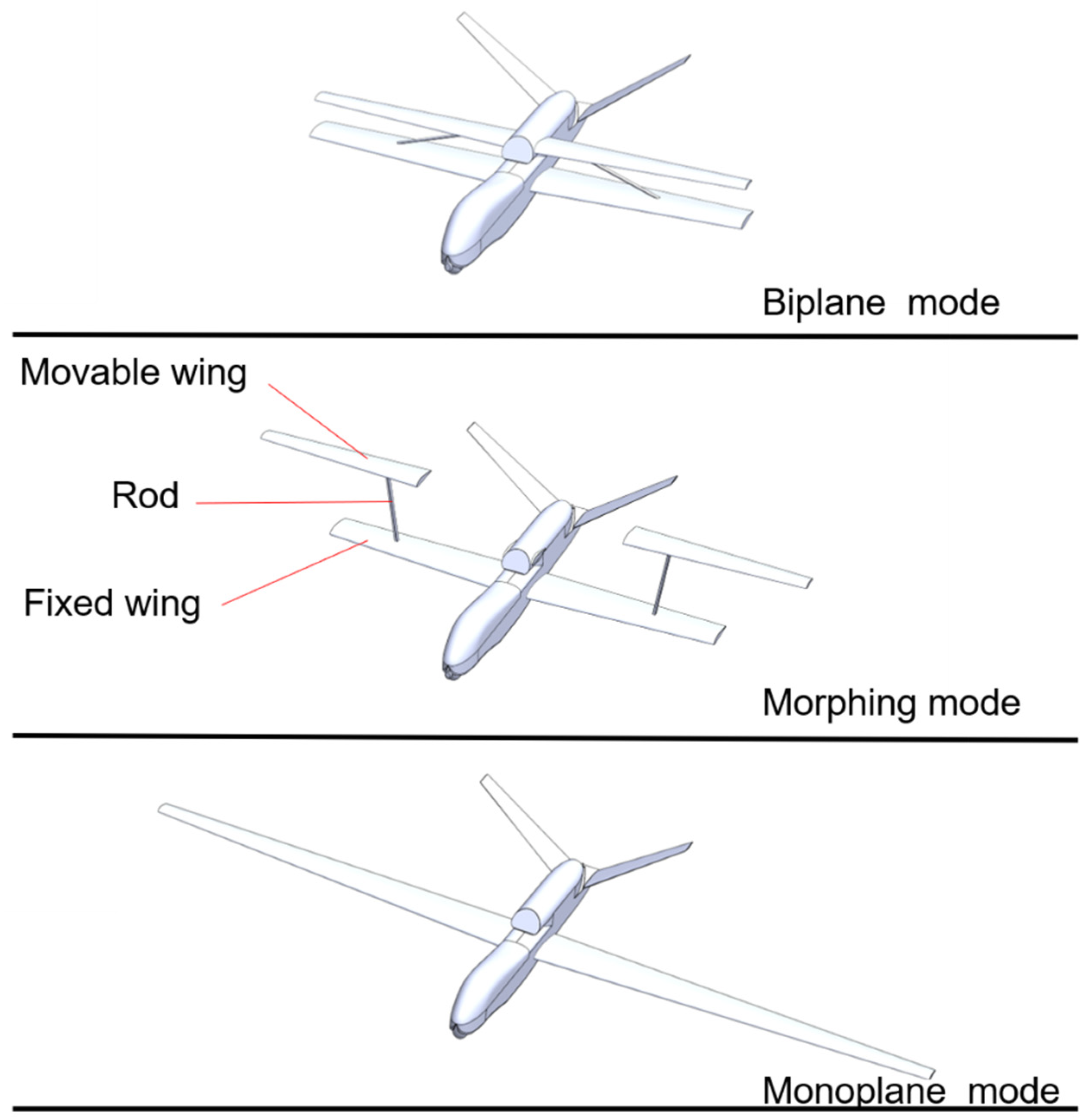
The wing of the mono-biplane aerodynamics-driven morphing aircraft was divided into two parts: the fixed wing (inner, lower wing) and the movable wing (outer, upper wing), and the two wings are connected by a rod. The movable wing rotates around a hinge on the connecting rod, and the rod rotates around a hinge on the fixed wing. The process of morphing is realized through these two rotations. Before landing, from a monoplane configuration, the two outer movable wings move upward and drive the connecting rod to rotate inward until the movable wings dock with the fuselage. The movable wings are then fixed above the fixed wings in parallel to form a biplane configuration. When the aircraft is ready to enter the cruise phase, the movable wings are unlocked from the fuselage. They are driven and controlled to “fly” spanwise, driving the connecting rod to rotate outwards until the fixed and movable wings become connected and become a complete monoplane wing with a large aspect ratio. During the “fly”, the movable wing is controlled to remain almost parallel to the fixed wing. When forming a monoplane wing, the connecting rod becomes part of the wing structure. The morphing process of the mono-biplane aerodynamics-driven morphing aircraft is shown in
Figure 1. Using this morphing technology, the aircraft can have a large span and aspect ratio for highly efficient cruising, while the wingspan is reduced by nearly half during takeoff and landing and low-altitude flight phases.
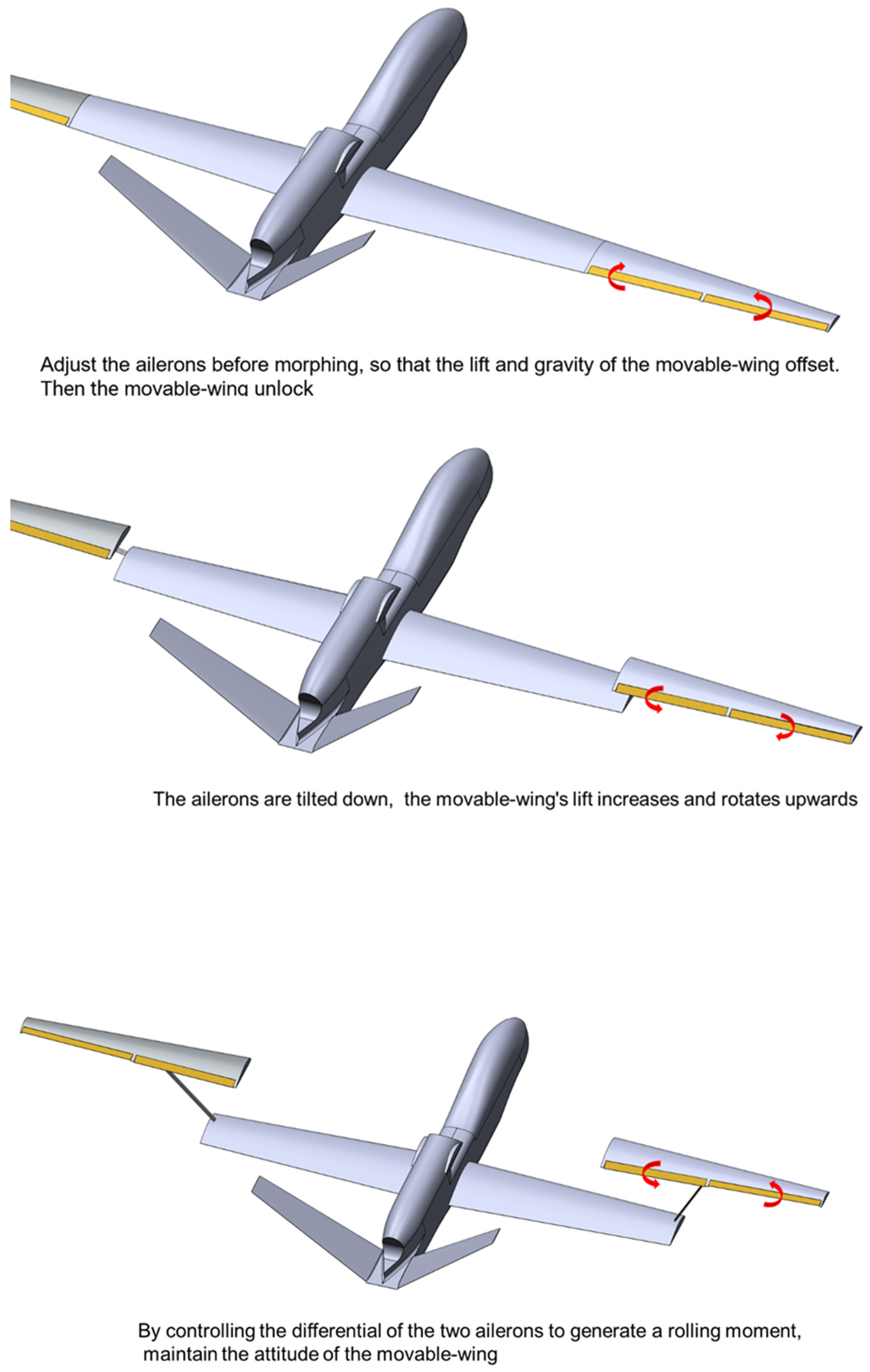
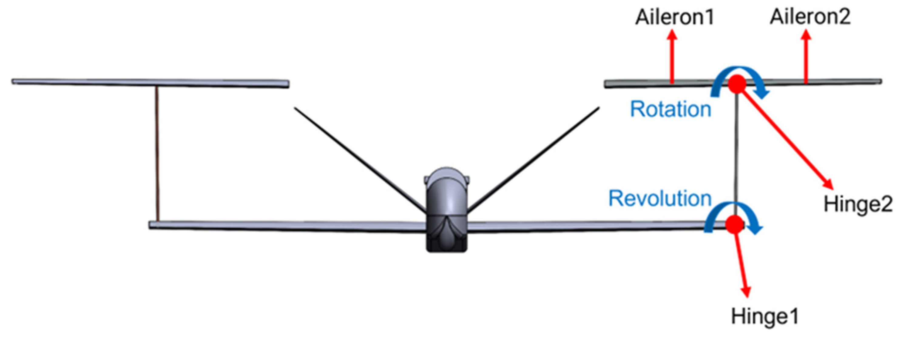
The connecting rod of the mono-biplane aerodynamics-driven morphing aircraft is articulated with the two wings. The morphing movement of the wing can be decomposed into the revolution of the connecting rod around the fixed wing and the rotation of the movable wing around the connecting rod. Ailerons are provided both inside and outside of the hinge on the movable wing. The direction and magnitude of the lift vector of the movable wing are changed by the deflection control of the ailerons, which drives the revolution of the movable wing and the connecting rod. When the aileron of the movable wing deflects upward, the lift is reduced, and the movable wing can be controlled to move downward. When the aileron of the movable wing deflects downward, the lift increases, and the movable wing can be controlled to move upward. At the same time, when the deflections of the two ailerons are not synchronized, the rolling moment will be generated to adjust the rotation angle of the movable wing around the rod. In the process of morphing, through the coordination of the two rotations, the movable wing, and the fixed wing can be kept parallel or slightly inclined to help the rotation. After rotating to the designated position, the movable wing and the fuselage or the movable wing and the fixed wing are locked, and morphing is completed. The whole morphing process is shown in
Figure 2. In this morphing process, each movable wing adds two degrees of freedom of rotation and revolution, while the aileron provides two control rudders, forming a dual-input dual-output control system as shown in
Figure 3. In the aerodynamic control scheme, the lift and gravity of the movable wing mostly offset each other, and the connection structure only needs to transmit the drag of the movable wing and the torque caused by the drag, which can effectively reduce the strength and rigidity requirements of the connecting rod and the hinge and reduce the structural weight.
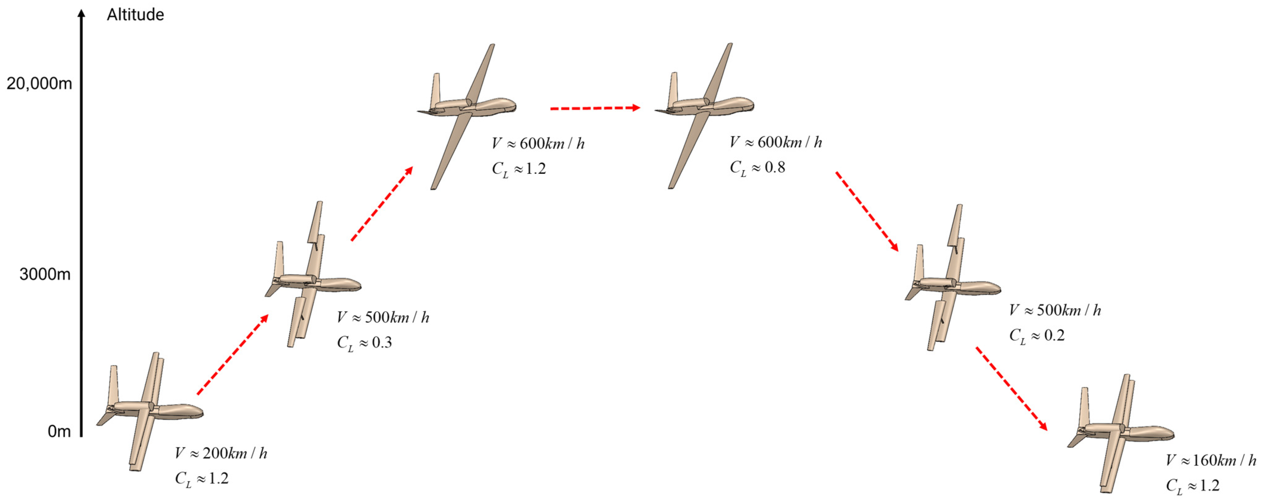
The mono-biplane aerodynamics-driven morphing aircraft can morph at a suitable height and speed according to its flight envelope.
Figure 4 shows a typical airplane flight profile. The morphing process is completed at low altitudes and high speeds. At this time, the air density is relatively high, which means that the angle of attack and lift coefficient required for flight is very low. In this state, the wing and aileron have sufficient linear lift, and only a small aileron deflection is required to complete the lift control.
3. Proof of Principle Feasibility
To comprehensively verify the feasibility of the mono-biplane aerodynamics-driven morphing aircraft, we manufactured the principal verification model and conducted a corresponding ground vehicle morphing test.
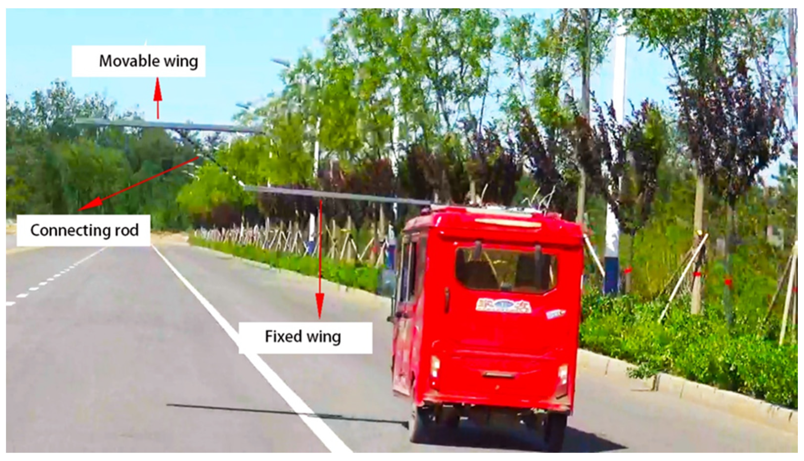
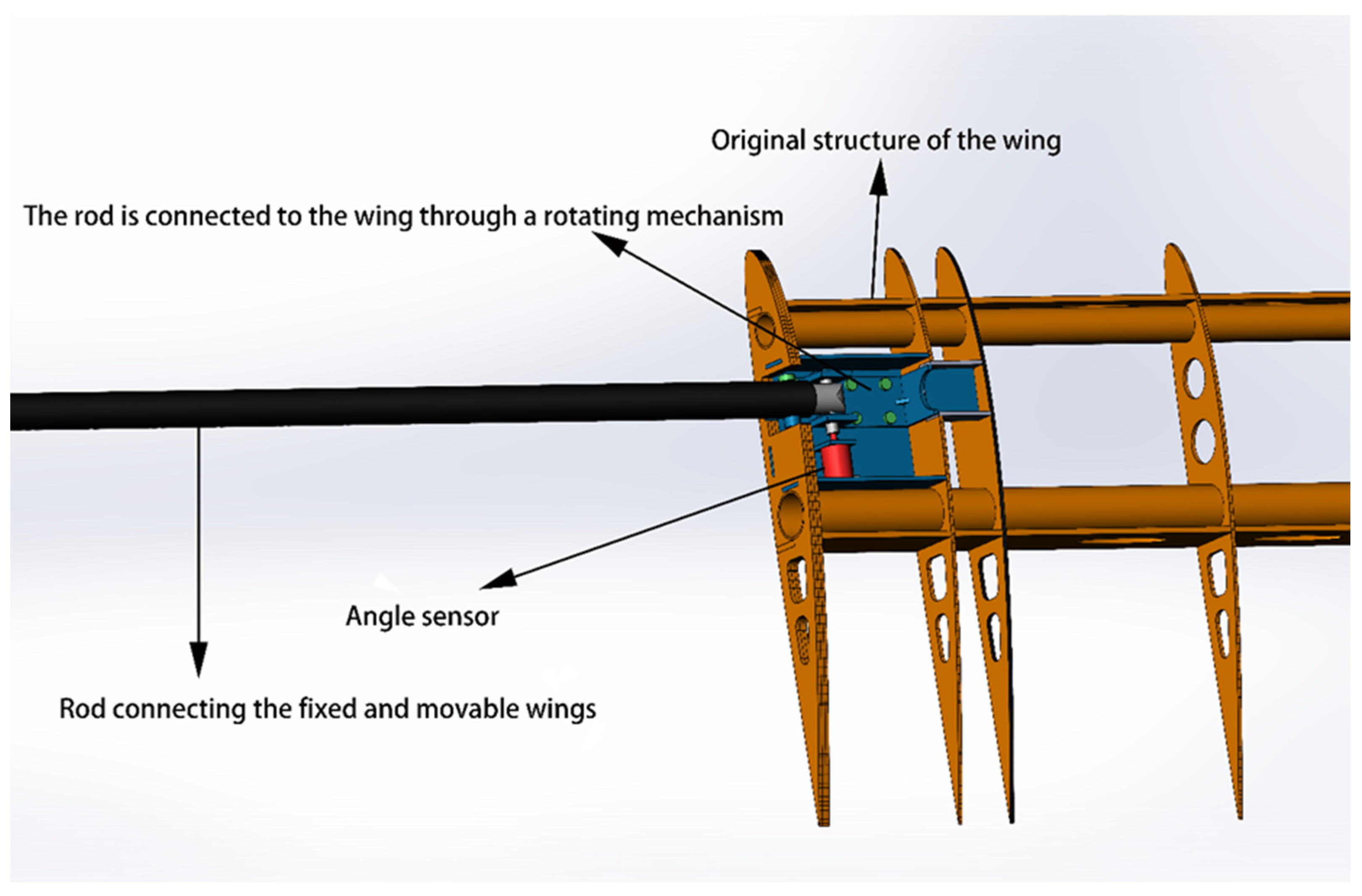
The model consisted of a fixed wing, a movable wing, and a connecting mechanism between the wings, while the inner side of the fixed wing was fixed to the car. The two wings each had a chord length of 0.3 m and a wingspan of 1.5 m. The wings had a multibeam layout with two ailerons, and the connecting mechanism consisted of a carbon fiber rod, a connecting structure fixed on the wings, and two angle sensors. The weight cost for morphing was approximately 20% of the structural weight of the wing. Considering that the structural weight coefficient of a typical aircraft is approximately 0.3 and the wing structure accounts for half [
19], the weight cost was approximately 3% of the MTOW, which does not have a serious impact on the performance of the aircraft. The principal verification setup is shown in
Figure 5 and
Figure 6.
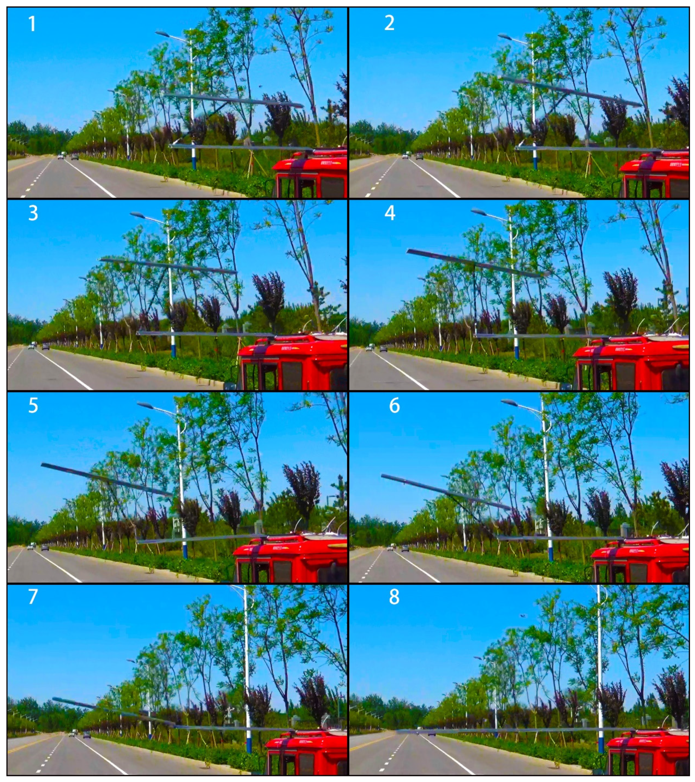
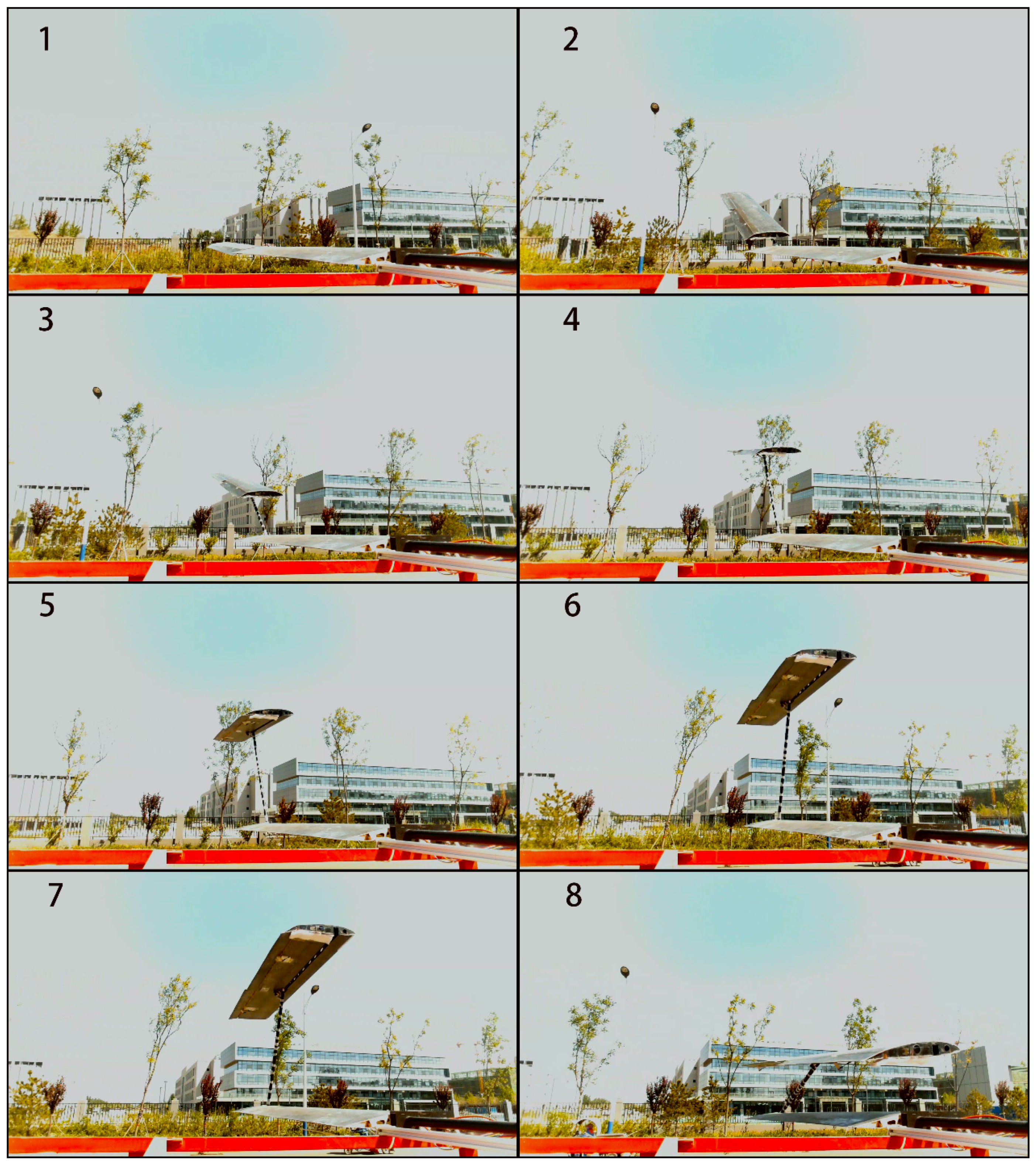
In the experiment, the angle sensors at the two rotating shafts were used to read the angle values of revolution and rotation, and the angular velocity value was further calculated through the microcontroller, generating the control signal to drive the aileron to a specific angle, completing the morphing through aerodynamic control. Two cameras with different views were used to record the folding and unfolding process of the wings as shown in
Figure 7 and
Figure 8. We can see that the wing completed the morphing process successfully. During the morphing process, the attitude changes of the movable wings were highly stable, which fully shows that aerodynamics-driven morphing is feasible.
4. Multidisciplinary Benefit Revenue Analysis
4.1. Analyzing Tool
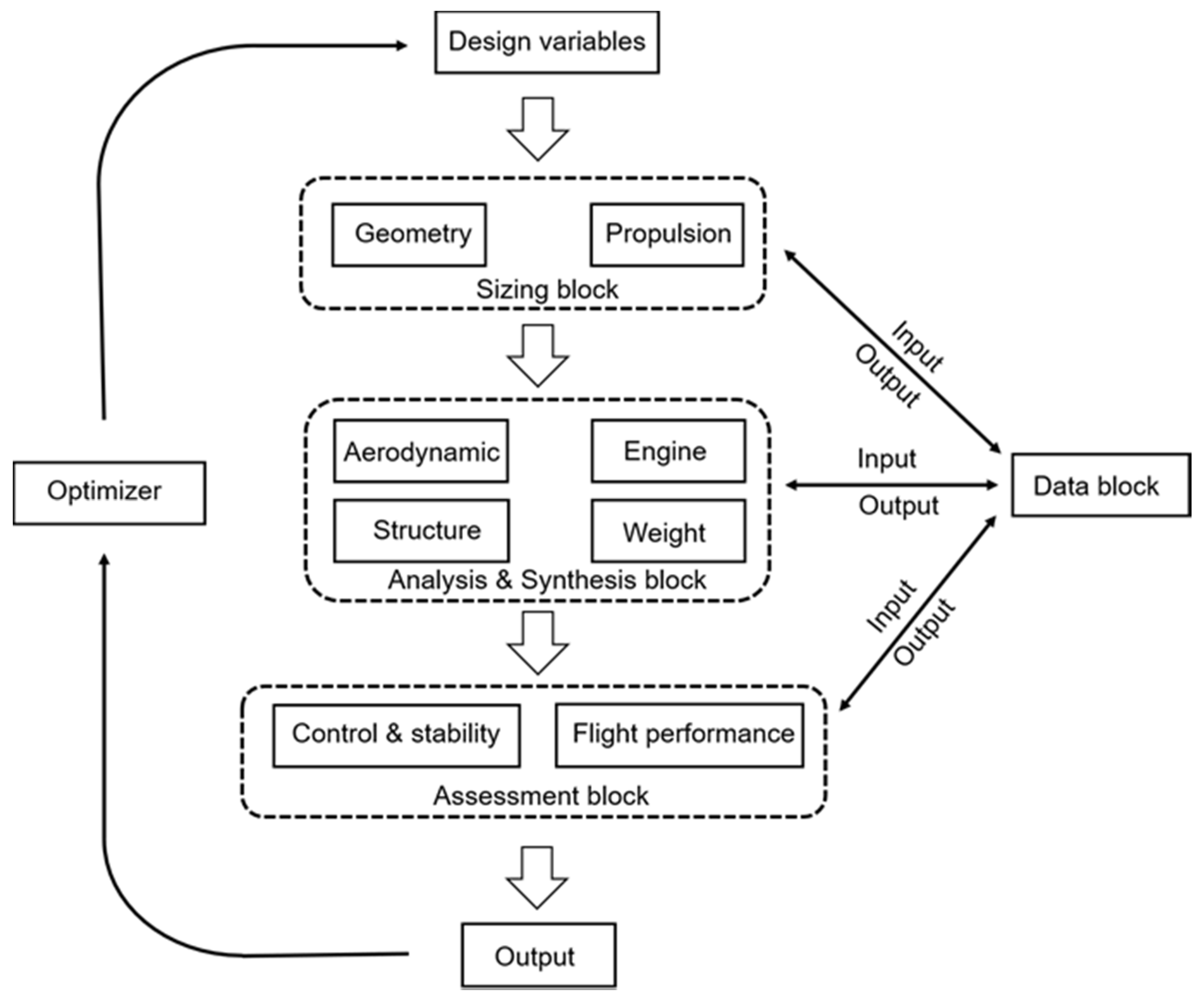
The multidisciplinary overall design tool ACADO [
20], independently developed by the research group, was used to evaluate the overall performance of the mono-biplane aerodynamics-driven morphing aircraft. ACADO adopts a modular design coupled with multiple modules such as weight, structure, propulsion, and aerodynamics. The calculation process is shown in
Figure 9. Its aerodynamic module integrated fast aerodynamic calculation programs, such as friction [
21] and idrag [
22], and combined several semiempirical methods to predict lift, various resistances, and dynamic derivatives [
23], and the weight structure module used a component-level engineering beam model method.
The modular structure of ACADO was suitable for the overall design and analysis of the newly conceptualized aircraft. Custom calculations and corrections could be made for unconventional calculation problems brought by the new concept’s layout. ACADO has been used in the analysis and design of newly conceptualized aircraft, such as supporting wing layout aircraft and natural laminar flow aircraft and has achieved good results [
20]. During our research on mono-biplane aerodynamics-driven morphing aircraft, for the aerodynamic characteristics of the biplane state, in terms of the weight cost of the morphing mechanism, etc., there was no empirical formula or support data; therefore, we established a physical model and used the finite element method and CFD method to perform accurate calculations and fused these calculation results into ACADO in the form of interpolation and fitting.
4.2. Design Baseline
A mono-biplane aerodynamics-driven morphing layout can reduce half of the takeoff and landing wingspan based on an existing aircraft to decrease the requirements for airport space and runway width. At the same time, the smaller moment of inertia and greater wing strength are also conducive to the aircraft’s resistance to gusts. It is also possible to further expand the wingspan based on an existing HALE aircraft and increase the ceiling altitude and range.
In the multidisciplinary analysis, we used the RQ-4A “Global Hawk” UAV as the design baseline. The cruising altitude of the RQ-4A is approximately 20 km, and its cruising lift coefficient is very high (approximately 1.2) due to the thin air, which is approximately twice that of ordinary civil airliners (approximately 0.5–0.6). As is well known, the induced drag is proportional to the square of the lift coefficient and inversely proportional to the aspect ratio. Therefore, the RQ-4A has a strong requirement for a large aspect ratio and is a suitable application object for mono-biplane aerodynamics-driven morphing.
In the analysis and comparison of mono-biplane morphing and other layouts, the fuselage and engine were consistent with those of the RQ-4A [
24], and only the wing parameters were different. Based on the RQ-4A, the influence of morphing on aircraft stability is also discussed.
4.3. Performance Comparison between Mono-Biplane Aerodynamics-Driven Morphing and a Conventional Layout
We first compared the performance of mono-biplane aerodynamics-driven morphing and a conventional layout. Referring to the RQ-4A UAV, two aircraft were designed with mono-biplane morphing and conventional monoplane layouts. The performance and range of the aircraft were compared, while the fuselage and engine parameters were the same as those of the RQ-4A. For reconnaissance aircraft, such as the RQ-4A, flight altitude is very important. Therefore, we carried out comparisons, while the wing area was the same; thus, the flight altitude of the aircraft could be kept constant.
In the calculation of aerodynamic and structural weights, ACADO’s original method was still used, and the weight cost of morphing was additionally considered. We calculated the force and moment of the movable wing and connecting rod through a CFD method and further calculated the weight of the rod using the finite element method. Several empirical formulas were used to calculate the weight penalty of the wing surface opening [
25], and the weight data of a carrier-borne aircraft with folded wings were used to estimate the weight penalty of the locking mechanism of the movable wing [
26]. The total weight penalty was conservatively set to 25% of the structural weight of the wing. The truss structure of the wing and the connecting rod enhanced the structural strength for takeoff and landing, which caused a reduction in the weight of the original wing structure and offset a part of the weight of the morphing mechanism. The actual weight cost may be substantially less than 25%.
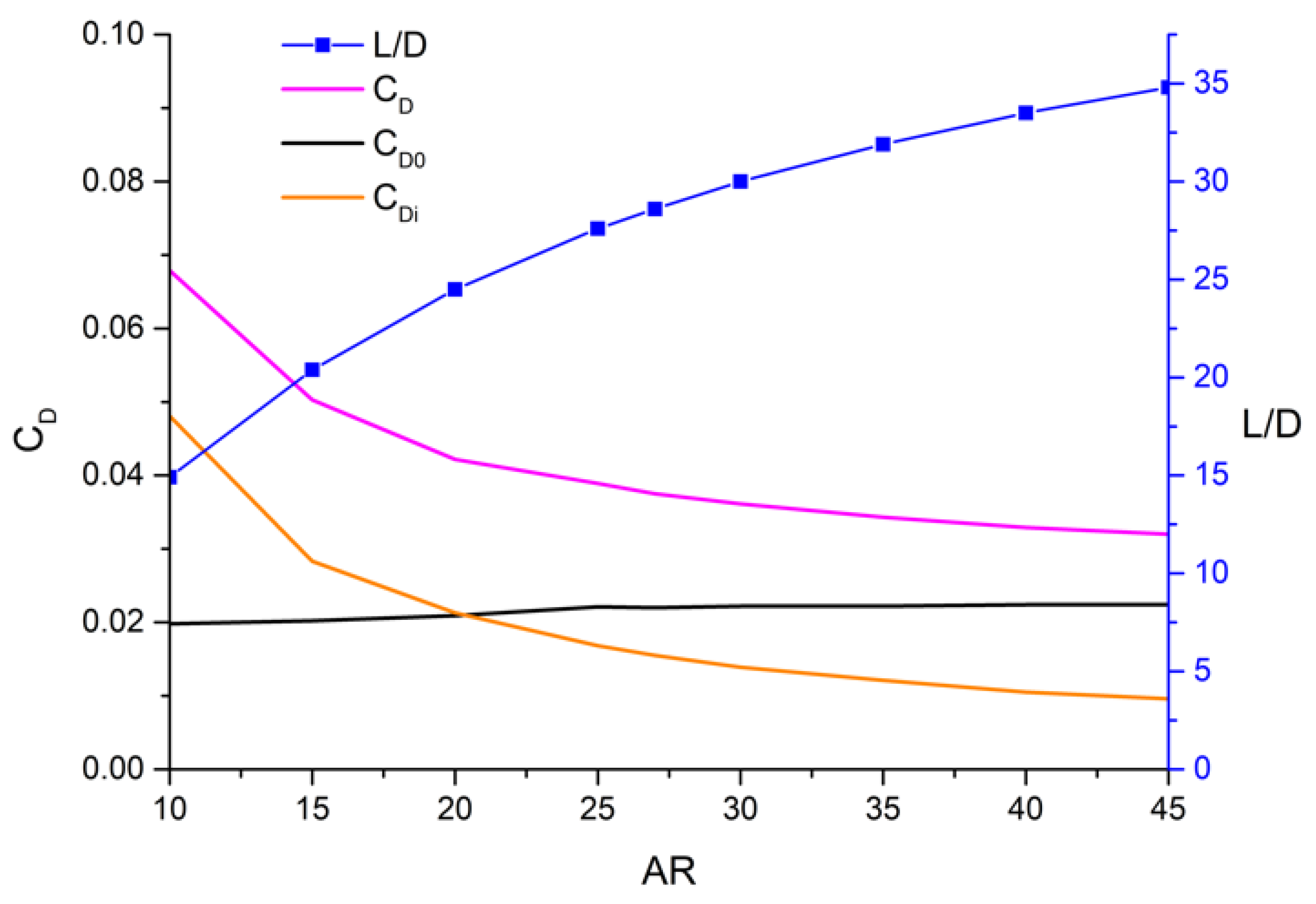
Figure 10 shows the drag and lift-to-drag ratio of the two aircraft at different cruise aspect ratios. When cruising, the mono-biplane morphing aircraft was in a monoplane state, and its aerodynamic shape was the same as that of a conventional aircraft; thus, the curves of the two aircraft were coincident. As the aspect ratio increased, the induced drag of the aircraft decreased significantly, but since the zero-lift drag was unchanged, the increase in the lift-to-drag ratio of the aircraft gradually slowed down.
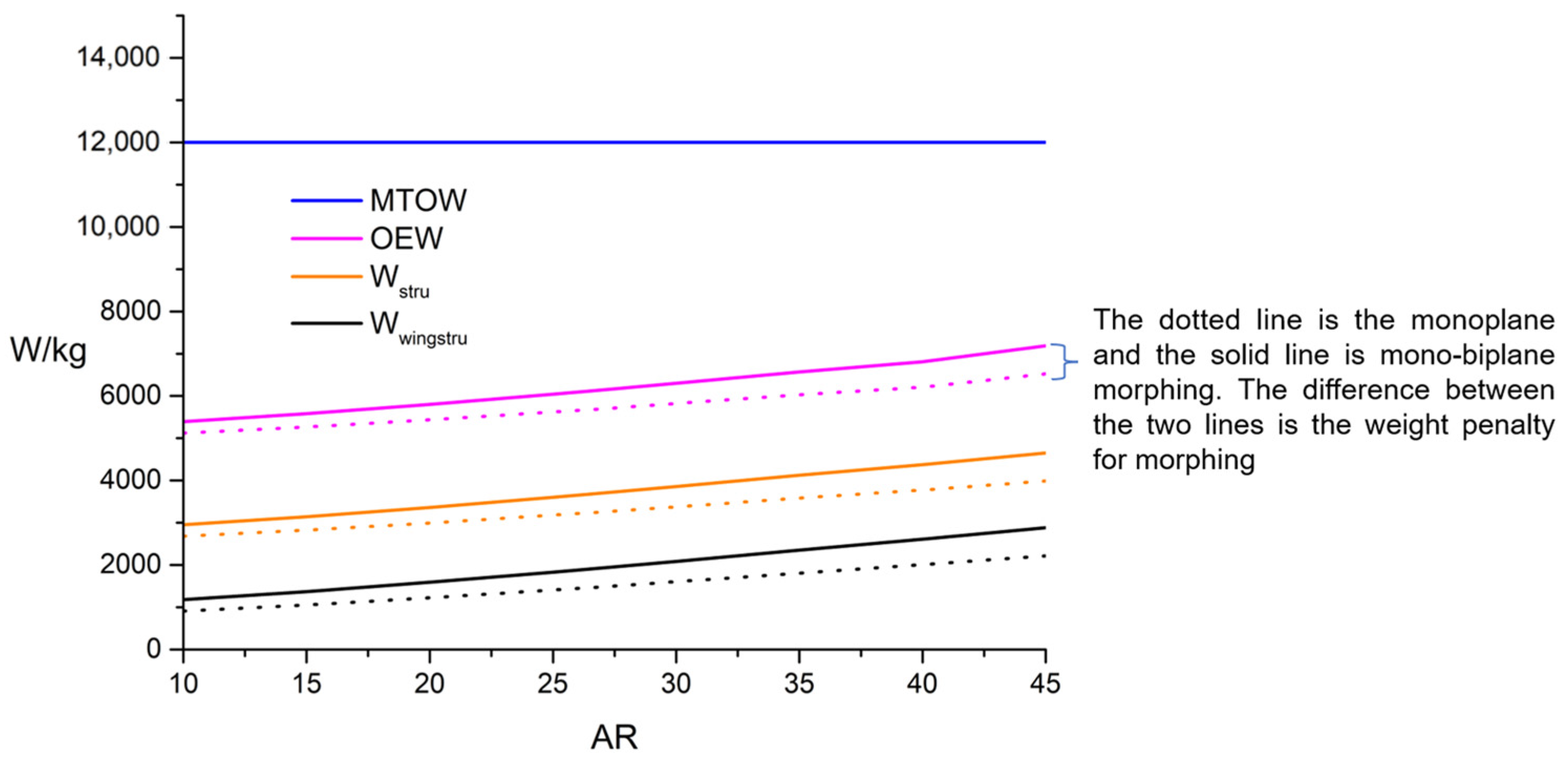
Figure 11 shows the weight distribution of the two aircraft under different cruise aspect ratios. The solid line in the figure represents the mono-biplane morphing aircraft, and the dashed line shows the conventional monoplane. When the MTOW was 12 t, the aspect ratio increased, and the structural weight of the wing continued to increase, which also means that less fuel can be loaded. Therefore, the two airplanes should have the best aspect ratio and wingspan for the range.
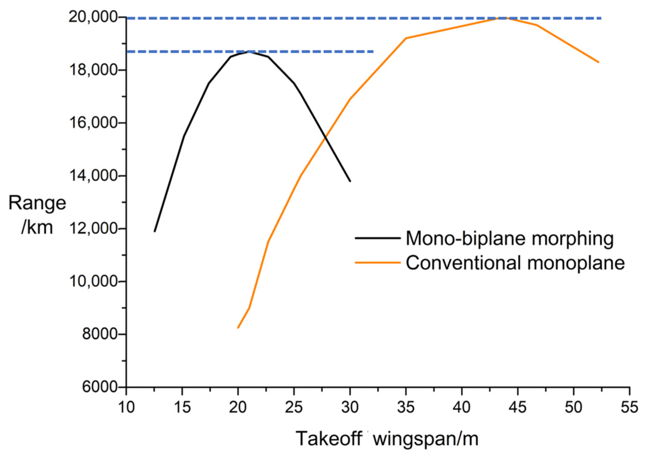
Figure 12 shows the range of the two aircraft under different takeoff and landing wingspans. When the range of the mono-biplane morphing aircraft was the best, the takeoff and landing wingspan was approximately 20 m, and the corresponding cruise wingspan was approximately 40 m. The wingspan of the conventional layout under the best range was also approximately 40 m. The maximum range of the mono-biplane morphing was reduced compared to the conventional monoplane due to the morphing weight penalty. However, when the takeoff and landing wingspans of both aircraft were limited to less than 25 m, the mono-biplane morphing aircraft had a significant advantage. If the zero-lift drag of the aircraft could be reduced or the structural weight of the wing reduced, the advantage would be expanded.
4.4. Performance Comparison between Mono-Biplane Aerodynamics-Driven Morphing and Other Layouts in Representative Application Scenarios
Based on the above research, we selected a typical application scenario for mono-biplane aerodynamics-driven morphing, that is, a high-altitude aircraft taking off and landing at a small airport or an aircraft carrier. In this scenario, a more detailed comparison of the performance of mono-biplane morphing and other layouts was conducted.
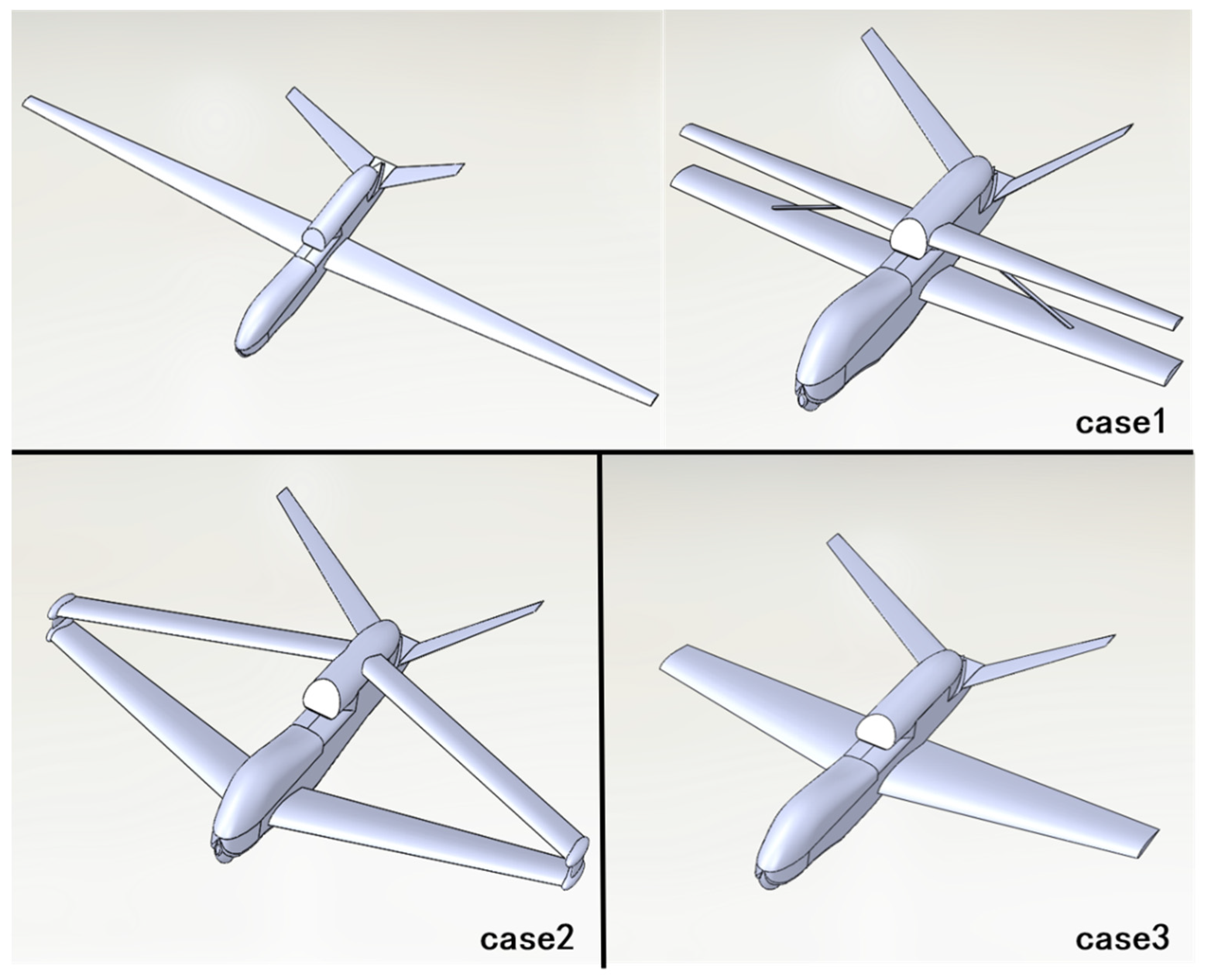
Still referring to the RQ-4A, the aircraft was designed according to mono-biplane morphing, connecting wing, and conventional monoplane layouts. The three layouts are shown in
Figure 13. The MTOW was set to 12 t, and the takeoff/landing wingspan was strictly limited to 20 m, considering the requirements for small airports or aircraft carriers. A normal flap/flaperon was also added to these aircraft to improve takeoff/landing performance. The wing load and wing area of the three aircraft were the same to ensure the same cruising altitude. In addition, the engine system, fuselage, and other parameters were still the same as those of the RQ-4A. All design constraints are shown in
Table 1.
Regarding the connecting wing layout, we are optimistic that it can reduce the structural weight of the wing by 20% compared to the conventional layout with the same aspect ratio after being fully optimized [
27]. Other calculation methods of the aerodynamics and structure were consistent with the above.
Considering the aspects of aerodynamics and structure comprehensively, the performance comparisons of the three configurations are shown in
Table 2. Due to the larger aspect ratio and the weight cost of morphing, the structural weight of the mono-biplane aerodynamics-driven morphing aircraft increased, and the fuel was reduced, but its cruise lift–drag ratio greatly improved compared with the other two aircraft; thus, it still has a great advantage in terms of range. At the same time, due to the loss of the lift in the biplane state, its takeoff distance slightly increased compared to the monoplane solution. On the whole, under this design constraint, the range of the mono-biplane morphing aircraft increased by 50%, compared with the connected wing layout, and by more than 110%, compared with the conventional layout. This shows the great application value of mono-biplane morphing technology.
4.5. Aircraft Stability during Morphing
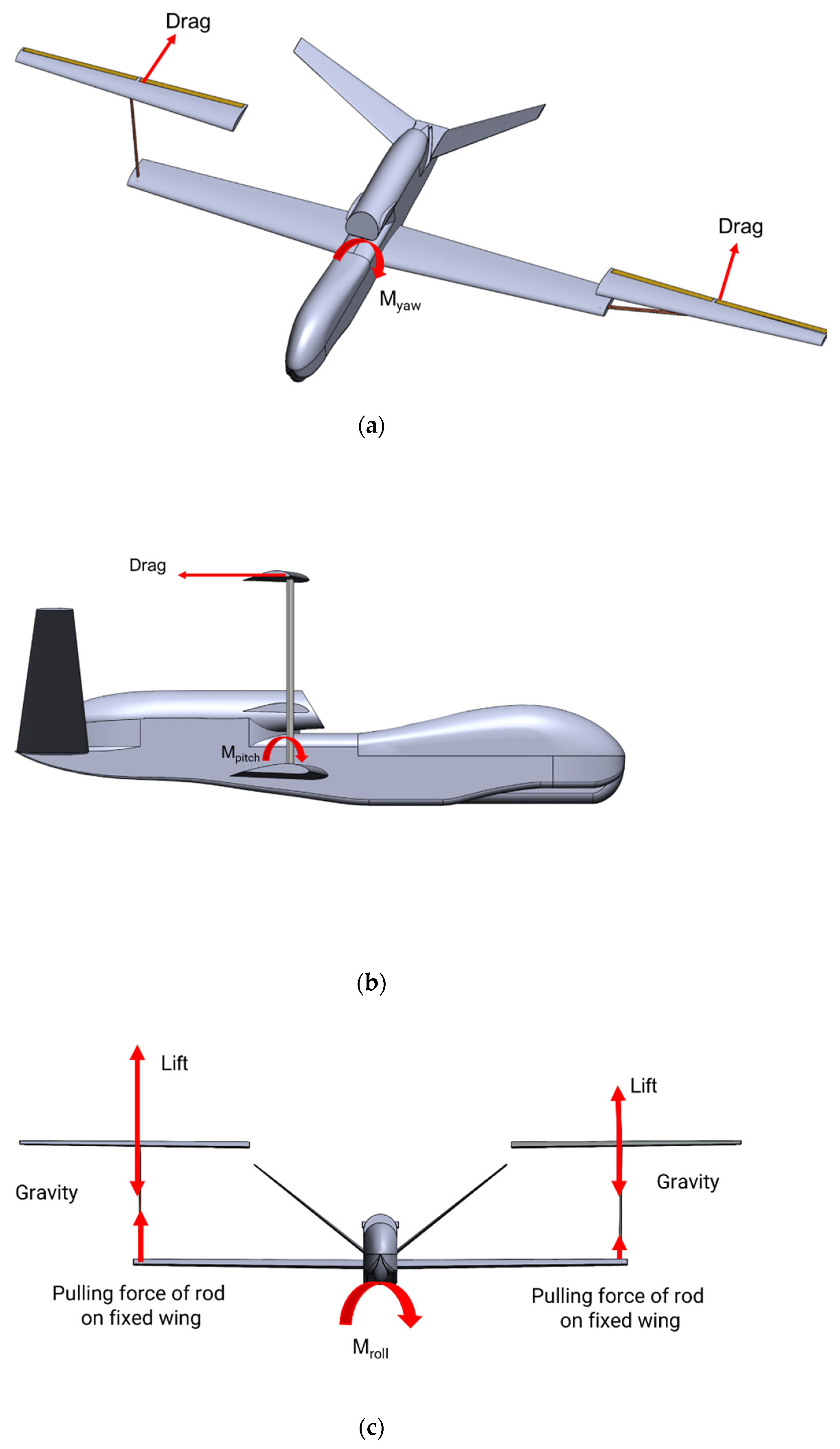
In addition to the feasibility of aerodynamically driven morphing, we also need to pay attention to the effect of morphing on flight stability. In the process of aerodynamically driven morphing, most of the pulling force of the connecting rods on both sides will be offset through the control of lift, but the remaining pulling force transmitted by the rods will still produce a rolling moment on the aircraft. The asymmetric drag of the two movable wings will cause a yaw moment. During the morphing process, the drag of the movable wing produce a pitching moment. The generation mechanism of these moments is shown in
Figure 14.
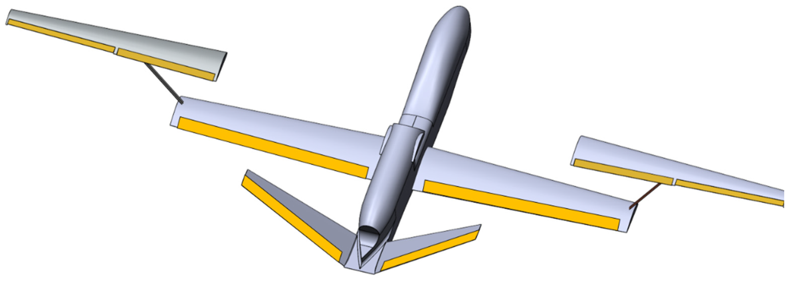
We took the case 1 aircraft in the previous section as the research object. On this basis, the maximum moments generated by morphing and the maximum control force provided by the rudders were calculated separately. The comparison of the two values could intuitively reflect the influence of morphing on flight stability. The layout of the rudders of this aircraft is shown in
Figure 15, while the wing and rudder parameters are listed in
Table 3.
As shown in
Figure 14a, when the wings on both sides are extremely asymmetric, that is, when the movable wing on one side remains in the monoplane state and the wing on the other side remains in the biplane state, the drag of two unsymmetrically movable wings produces the maximum yaw moment. As shown in
Figure 14b, when the two movable wings rise to the apex of motion, the drag of the movable wing produces the maximum pitching moment. For these two moments, we first used the CFD method to calculate the drag of the movable wing and then calculated the moment. As shown in
Figure 14c, when the lift of the two movable wings were not the same, a rolling moment would be generated in the aircraft. When the movable wing is at the top of the motion, the movable wing is perpendicular to the rod, and the unbalanced lift transmitted through the rod is the largest. According to the test data of the ground vehicle morphing test, we found that the variation range of the movable wing’s lift would not exceed 20%; thus, here, we assumed that the lift of one movable wing was 120% of the lift of the other wing and calculated the resulting rolling moment on this basis. Finally, we need to pay attention to the maximum control moment that can be generated by the aircraft. According to the design parameters of the wings and tails in
Table 3, as well as the area ratio of ailerons, rudders, and elevators, we estimated the manipulation derivative of the aircraft [
28]; then, we calculated the maximum rolling moment, pitching moment, and yaw moment that these control surface could provide. This formula-based calculation was accurate enough for the conceptual analysis.
The calculation results are shown in
Table 4. The yaw moment and pitch moment generated in the morphing process were completely within the control moment limit of the rudder and elevator, and the rolling moment under the 20% imbalance of the lift on both sides was also completely controllable. The results show that a certain degree of asymmetry will not have a fatal impact on the safety and controllability of the aircraft itself during the morphing process.
5. Conclusions
This paper proposed the concept of a mono-biplane aerodynamics-driven morphing aircraft and carried out conceptual research. The mono-biplane aerodynamics-driven morphing aircraft had two modes: a biplane and a large aspect ratio monoplane, which largely reduces the requirements of high-altitude long-endurance aircraft on takeoff/landing sites and brings better low-altitude flight performance. Aerodynamics-driven morphing greatly simplifies the morphing mechanism and reduces the penalty for morphing. The physical model was made, and a ground vehicle morphing test was conducted. The test results showed that aerodynamics-driven morphing is completely feasible. Based on the results of the ground vehicle morphing test, the degree of freedom of the aircraft can be further expanded, and follow-up studies can be carried out.
A mono-biplane aerodynamics-driven morphing layout can reduce half of the takeoff and landing wingspan based on the current aircraft, so that it has better takeoff and landing performance and wind resistance. It is also possible to further expand the wingspan based on an existing aircraft and increase the ceiling altitude and range. This article used a multidisciplinary method to evaluate the potential application value of the mono-biplane aerodynamics-driven morphing aircraft, and the influence of the morphing process on aircraft stability was evaluated. The analysis results show that mono-biplane aerodynamics-driven morphing technology can have excellent application value.


