Article

Design and Analysis of MataMorph-3: A Fully Morphing UAV with Camber-Morphing Wings and Tail Stabilizers

Department of Mechanical Engineering, California State University, Northridge, Northridge, CA 91330, USA
*
Author to whom correspondence should be addressed.
Aerospace 2022, 9(7), 382; https://doi.org/10.3390/aerospace9070382
Submission received: 10 June 2022 / Revised: 8 July 2022 / Accepted: 8 July 2022 / Published: 14 July 2022
(This article belongs to the Special Issue Advances in Aerospace Sciences and Technology III)

Abstract

:
Conventional aircraft use discrete flight control surfaces to maneuver during flight. The gaps and discontinuities of these control surfaces generate drag, which degrades aerodynamic and power efficiencies. Morphing technology aims to replace conventional wings with advanced wings that can change their shape to control the aircraft with the minimum possible induced drag. This paper presents MataMorph-3, a fully morphing unmanned aerial vehicle (UAV) with camber-morphing wings and tail stabilizers. Although previous research has presented successful designs for camber-morphing wing core mechanisms, skin designs suffered from wrinkling, warping, or sagging problems that result in reduced reliability and aerodynamic efficiency. The wing and tail stabilizers of MataMorph-3 feature hybrid ribs with solid leading-edge sections that house servomotors, and compliant trailing-edge sections with integrated flexible ribbons that are connected to the servomotors to camber-morph the ribs. Thin laminated carbon fiber composite skin slides smoothly over the compliant rib sections upon morphing, guided by innovative trailing-edge sliders and skin-supporting linkage mechanisms strategically located between the ribs. Sample prototypes were built and tested to show the effectiveness of the proposed design solutions in enabling smooth camber-morphing. The proposed design provides a better alternative to stretchable skins in morphing airplane designs through the concept of skin sliding.

1. Introduction

Morphing vehicles have become a contemporary concept of interest in aeronautics research due to advances in materials, structures, and controls [1]. For aircraft applications, these advances have the potential to improve the current efficiency, affordability, and environmental compatibility of the private and commercial aerospace industries [2]. For decades, conventional aircraft have utilized flight discrete control surfaces, such as flaps, ailerons, rudders, and elevators, to maneuver during flight. These surfaces incorporate hinges and pivots that inherently introduce gaps and discontinuities in the aerodynamic profile, causing disturbances in the airflow around the aircraft. These disturbances induce vortices in the airstream, which increase drag and reduce aerodynamic and power efficiencies [3]. By eliminating or minimizing the number of discrete surfaces on an aircraft, the drag can be reduced, and the overall aircraft efficiency can be improved. Therefore, morphing structures that replace conventional hinged surfaces form a necessity for improving the flight performance of next-generation aircraft [4,5,6].
Morphing aircraft structures are not a new concept. For years, pioneer aviators and engineers have been inspired by the seamless shape-changing capabilities of birds and other living organisms found in nature [3]. However, they were limited in their designs due to the highly rigid materials available at these times [1]. Today, new advances in material technologies have led to the development of morphing designs that are lightweight and aerodynamically superior to yesterday’s materials [7]. According to Barbarino et al. [3], aircraft wing morphing can be classified into three categories: planform alteration, out-of-plane transformation, and airfoil adjustment. Planform (or in-plane) alteration causes geometric changes to the wing, in which the cross-section of the airfoil does not change [8]. Examples include sweep-, span-, and chord-morphing designs. Out-of-plane transformation deforms the wing out of its plane, and includes spanwise bending, twist-, and dihedral-morphing. Finally, airfoil adjustment, which causes the airfoil’s cross-sectional shape to change, includes camber-morphing, and thickness adjustment. Recent examples of unmanned aerial vehicle (UAV) designs that feature one or two morphing actions include the Transformer aircraft [9] with span-morphing wings, MataMorph-2 [10] with twist-morphing wings and camber-morphing tail stabilizers, and the ASAPP wing UAV [11] with wing span-morphing and passive pitching.
Much of the previously published research on aeronautical morphing structures has focused mostly on camber-morphing wings and adaptive trailing-edge technology [12,13,14,15,16,17,18,19,20]. Camber-morphing is a type of out-of-plane morphing that bends the camber line of the airfoil, varying the local lift distribution to control and maneuver the aircraft, essentially converting a low-lift airfoil shape into that of a higher performance, high-lift airfoil. Conventional aircraft control the camber of the wing by utilizing trailing-edge discrete surfaces, whereas camber-morphing surfaces provide a smooth contour with no additional gaps, thus avoiding the large drag profiles associated with conventional control surfaces. Majid and Jo [14] conducted a comparative aerodynamic performance analysis of camber-morphing and conventional airfoils. This analysis validated the benefits of variable camber-morphing wings compared to conventional ones, and proved their superiority in generating higher aerodynamic efficiency, agility, and maneuverability. Extensive research has also been conducted proposing designs for camber-morphing ribs [15,16,17,18]. One contribution by Woods and Friswell in 2012 [19] presented the Fish Bone Active Camber (FishBAC) design. Variations of the FishBAC design were presented by Bishay et al. [16] as a shape-memory alloy (SMA) actuated tail structure, and by Schlup et al. [10] in the tail of MataMorph-2. Jo and Majid [20] recently performed a CFD analysis of a camber-morphing airfoil in transition, and showed that as the camber rate increases, the aerodynamic behavior changes linearly.
A prominent challenge in wing morphing is the design of the skin. Ideally, a morphing skin is a continuous surface that can adapt to the contour of the morphing body but remains structurally solid and stable to resist aerodynamic loads. This requires the skin to have conflicting structural requirements, including low in-plane stiffness and high out-of-plane bending stiffness [21]. Aeroelastic materials that can handle high strain while maintaining a linear elastic profile are thought to be ideal for use in morphing aircraft skin and morphing surfaces [22]. Ahmad and Ajaj [23] performed a multiaxial mechanical characterization study on latex skin for morphing wing applications. Thill et al. [24] presented an extensive review of various flexible skins and novel material concepts, emphasizing the use of segmented and corrugated structures, reinforced elastomers, and flexible matrix composite tubes. Another approach taken by Rediniotis et al. [25], presented a bio-inspired morphing skin with sliding segmented rigid panels for a hydrofoil, which showed promising results for out-of-plane camber-morphing.
This paper presents “MataMorph-3,” or MM-3, a fully morphing UAV that incorporates seamless sturdy camber-morphing surfaces in its wings and tail stabilizers. The design utilizes thin laminated carbon fiber composite skin attached to 3D printed trailing-edge slider mechanisms. When cambering, the skin is free to slide over the core of the wing or tail stabilizer that is actuated using servomotors housed in the ribs. This allows the exterior surfaces to be both continuous and resistive to aerodynamic loads. In addition, skin-supporting linkage mechanisms are strategically placed between rib sections to ensure that the skin stays in contact with the ribs and maintains the desired aerodynamic profile while cambering. This skin design eliminates the need for stretchable skin, extensively reported in the literature [26,27,28], that results in wrinkling, warping, or sagging problems. The ribs feature a hybrid design with compliant trailing-edge sections, inspired by the FishBAC design, and rigid leading-edge sections attached to load-bearing carbon fiber spars. The spars connect to the fuselage via 3D-printed mounts on a carbon fiber central boom that acts as the main support structure for the wings and empennage. The wing mounts allow the wings to be shifted forward or aft for fine-tuning the position of the UAV’s center of gravity (CG).
The rest of this paper is organized as follows: Section 2 presents materials and methods, including the developed preliminary design and sizing computer application, and the description of the main systems and structures in MM-3 (wing, empennage, fuselage, and avionics). Section 3 presents and discusses the results obtained from the finite element analysis (FEA) studies, computational fluid dynamics (CFD) studies, and experimental testing done on the manufactured proof-of-concept models. Section 4 provides final conclusions and a summary.

2. Materials and Methods

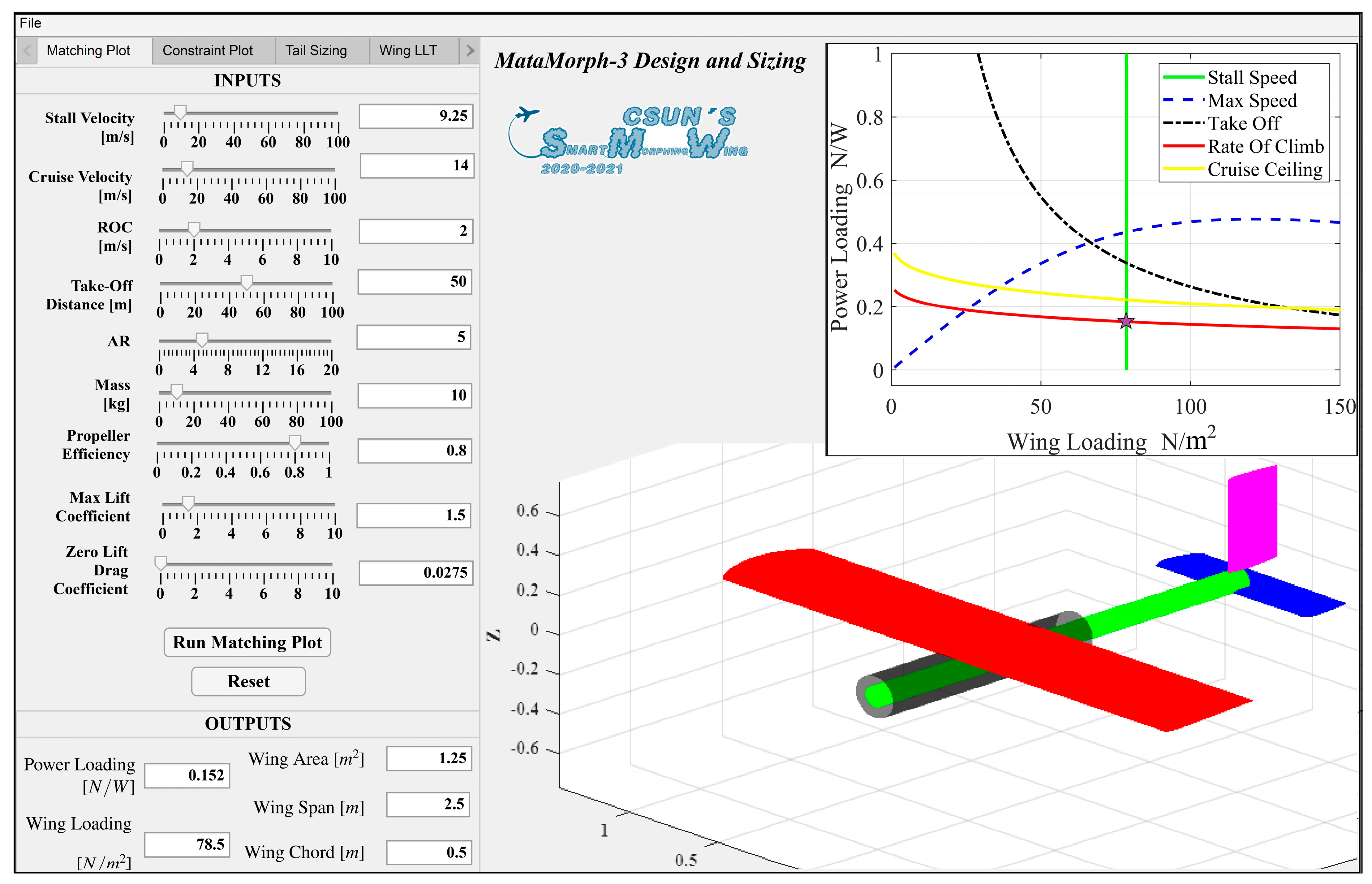
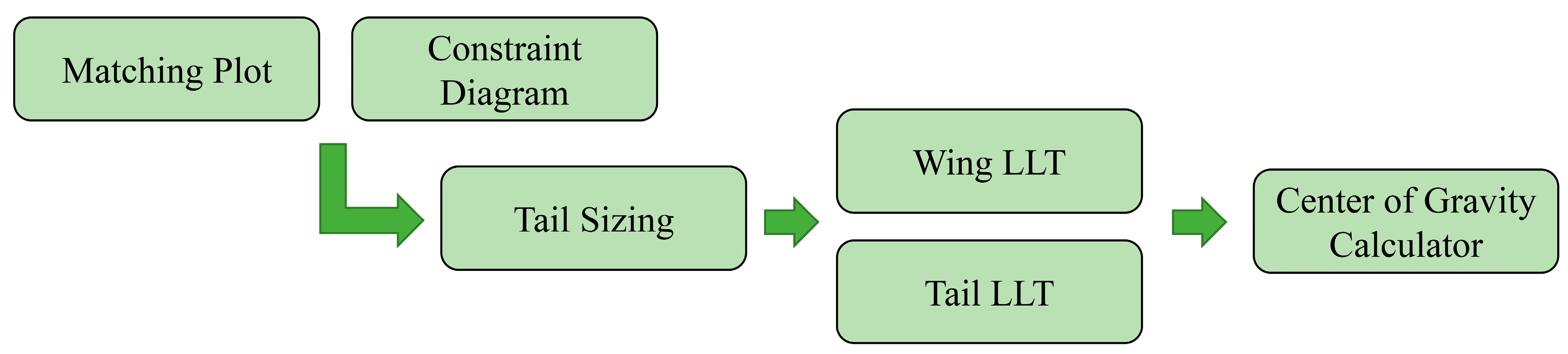
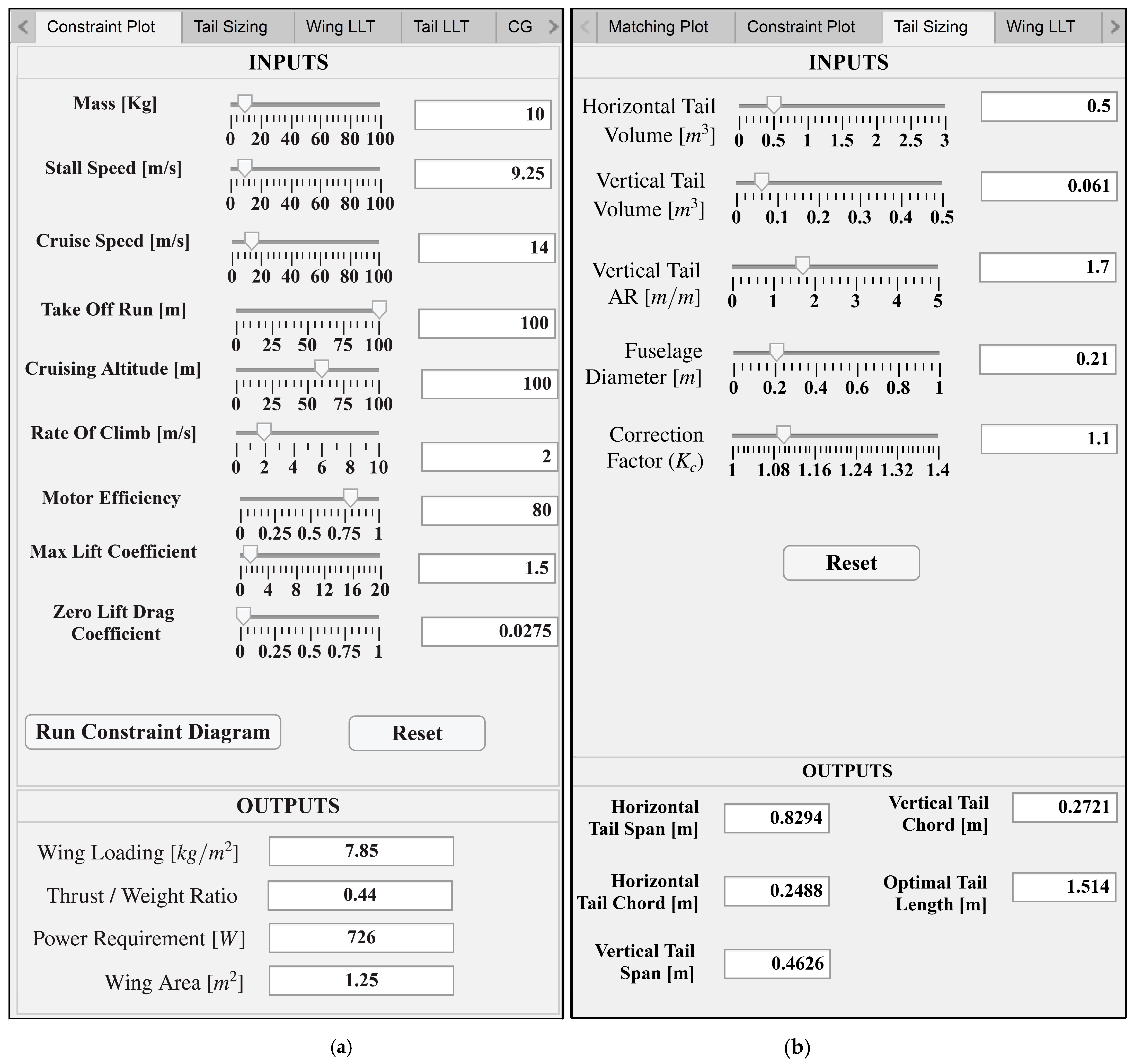
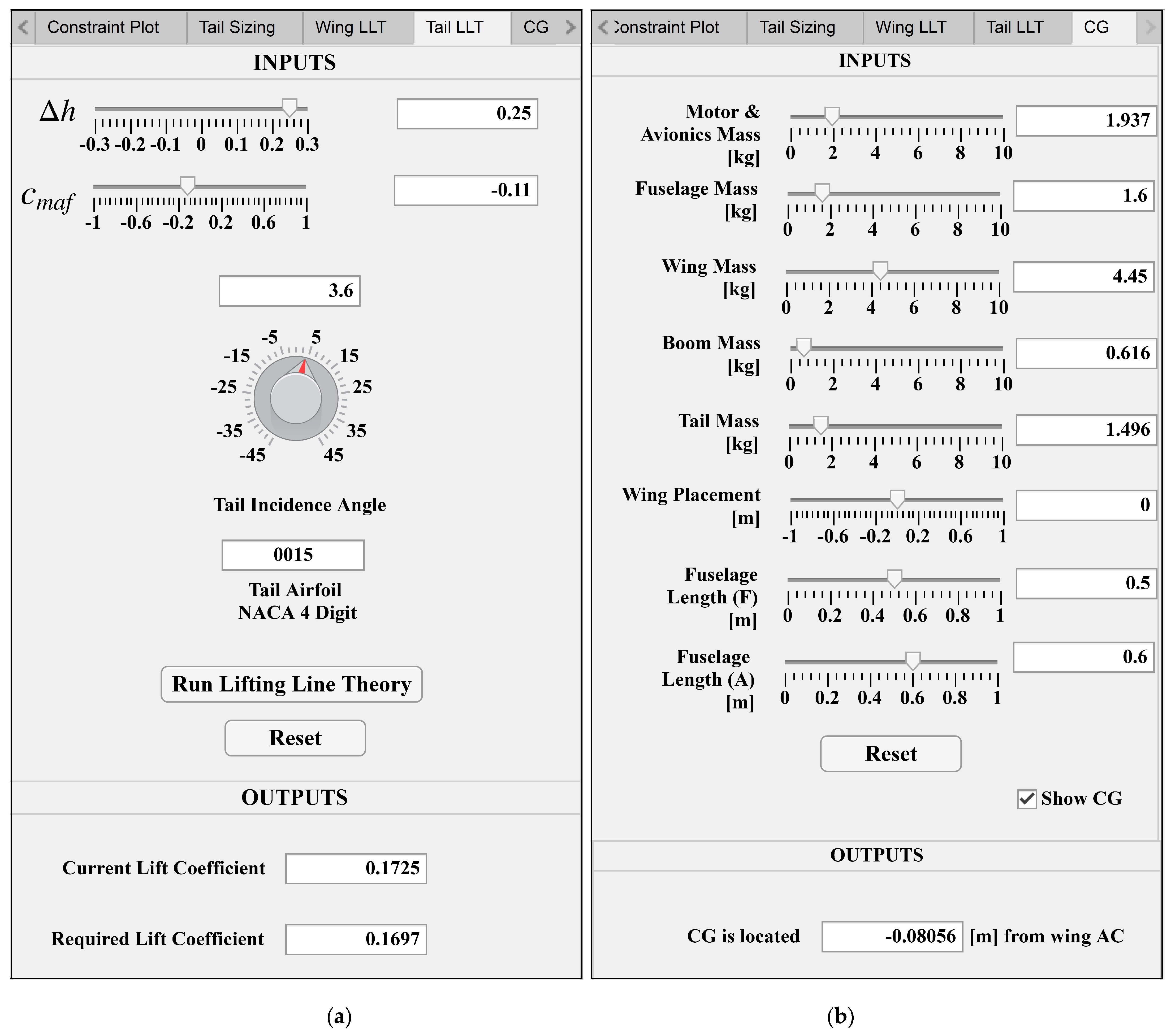
2.1. Preliminary Design and Sizing

A MATLAB application, shown in Figure 1, was developed (version 2020a) to aid in the design and sizing of MM-3. The app implements multiple tools with a graphical interface to help determine the optimal flightworthy parameters for the wing, motor, empennage, and center of gravity. Based on user’s input parameters, a generic UAV is dynamically displayed in the display area.
The first pair of tools in the app are the “Matching Plot” [29,30] and the “Constraint Diagram” [31], which enable selection of the required wing loading and power loading. The “Tail Sizing” tool aids in selecting the geometric parameters of the tail’s vertical and horizontal stabilizers based on the selected wing and fuselage parameters. The lift distribution plots on the wing and tail stabilizer surfaces can then be obtained based on the Lifting Line Theory (LLT) using the “Wing LLT” and “Tail LLT” tools. From the calculated total generated lift force, wing and tail parameters can be adjusted to realize the required lift force. Finally, the “Center of Gravity Calculator” tool estimates the longitudinal CG location using weights of various components and their locations.
Figure 2 shows a flowchart of the process used to design MM-3 utilizing the developed application. The design process mainly followed the arrows in the figure, but given the iterative nature of design, some parameters had to be adjusted to ensure that the best flight performance would be achieved. The design process began by determining the required wing area and motor size using the matching plot and the constraint diagram. Both techniques use the weight of the UAV as the main parameter and are used to size the wing and engine [29,30,31]. The design point in both techniques determines the necessary wing area and required power. The estimated maximum takeoff mass of MM-3 used in the calculation was 10 kg. A takeoff distance of 50 m was selected based on the available runway lengths at nearby airfields, and a cruise ceiling of 100 m was selected due to altitude restrictions. Density at sea level was used throughout the design process. A stall speed of 9.25 m/s and a cruise speed of 14 m/s were selected to provide sufficiently large operating margins between the two speeds. An average propeller efficiency of 80% was chosen since typical propeller efficiency ranges from 0.75 to 0.85. The wing aspect ratio (AR) was taken to be 5.
The matching plot is a power loading versus wing loading plot based on five different constraint equations: stall speed, maximum speed, maximum rate of climb, maximum takeoff distance, and cruise ceiling. Some parameters were initially averaged from the empirical data of UAVs of approximately the same size as MM-3. Figure 1 shows the matching plot, at the top right, generated based on the input parameters. The design region is to the left of the vertical (stall speed) line and below the lowest (rate of climb) line. The design point should be a point that satisfies all five equations and results in the smallest power system. The selected design point is highlighted in the figure by a star. It has a wing loading of 78.5 N/m2 (8 kg/m2) and a power loading of 0.152 N/W. The wing area was determined to be 1.25 m2 using selected wing loading. A power requirement of 645 W was calculated using power loading. The constraint diagram is similar to the matching plot, but accounts for a turn rate at a certain bank angle. A 45° bank angle was chosen [31]. The constraint diagram input parameters are shown in Figure 3a. The constraint diagram estimated a required power of 726 W, corresponding to a thrust-to-weight ratio of 0.44. This results in a 11.8% difference from that of the matching plot. To be conservative, the largest estimate of power was used.
Using the wing design parameters, the “Tail Sizing” and “Tail LLT” tools were used to select the appropriate span and chord lengths of the horizontal and vertical tail stabilizers, as well as the optimal tail length for longitudinal stability. “Tail Sizing” requires some user inputs, such as the horizontal tail volume coefficient, vertical tail volume coefficient, vertical tail AR, fuselage diameter, and the correction factor Kc [29]. Then, it dynamically updates the display and outputs. The tail Sizing input parameters are shown in Figure 3b. “Tail LLT” utilizes tail parameters, moment coefficient of the wing airfoil, c maf , and the difference between the position of the UAV’s CG and wing aerodynamic center (AC), Δh, to obtain the horizontal stabilizer’s angle of incidence, i h . i h  of approximately +3.6° was obtained producing a lift coefficient of 0.17 for maintaining longitudinal stability. The tail LLT input parameters are shown in Figure 4a, and a sample lift distribution on the horizontal tail is shown in Figure 5a.
After preliminary wing sizing, further wing parameters must be determined to ensure that the wing is generating enough lift while satisfying the design requirements. The Wing LLT tool considers wing parameters, such as AR, taper ratio λ , twist angle α t , wing setting angle, i w , and the selected airfoil parameters, such as the maximum thickness, camber percentage, zero-lift angle of attack α 0 , and the lift curve slope, to plot the lift distribution along the span of the wing. By adjusting these parameters, the values that achieved the required lift force were determined.
Finally, the “CG Calculator” tool estimates the position of the UAV’s CG by replacing the various components with point masses. The app allows the user to vary the masses of the motor, avionics, fuselage, wings, central boom, and empennage, as well as the location of the wings and fuselage, as seen in Figure 4b. The position of the CG was obtained relative to the AC of the wings and displayed on the model as an orange sphere, as shown in Figure 5b. The estimated CG of MM-3 was located 8 cm behind the wing’s AC, which proved to be close to the CG estimated from the final CAD model.

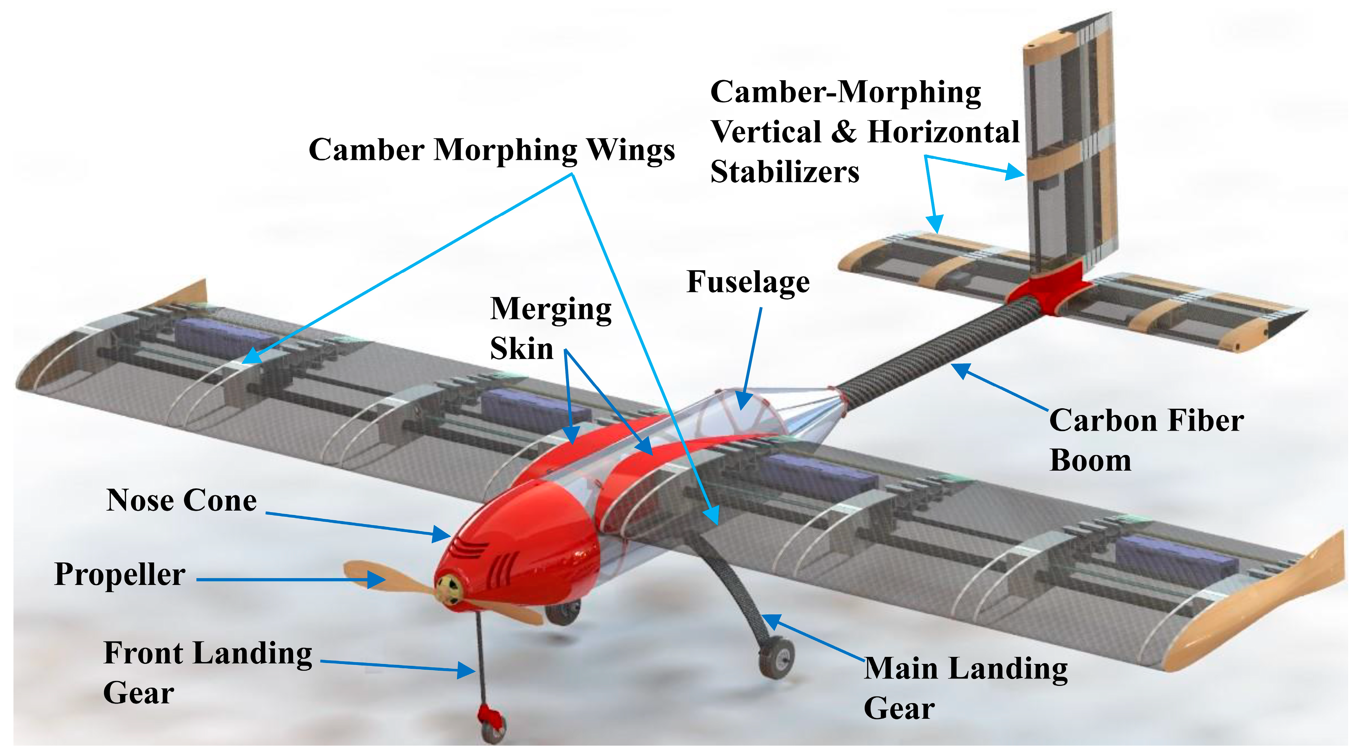
2.2. Model Description
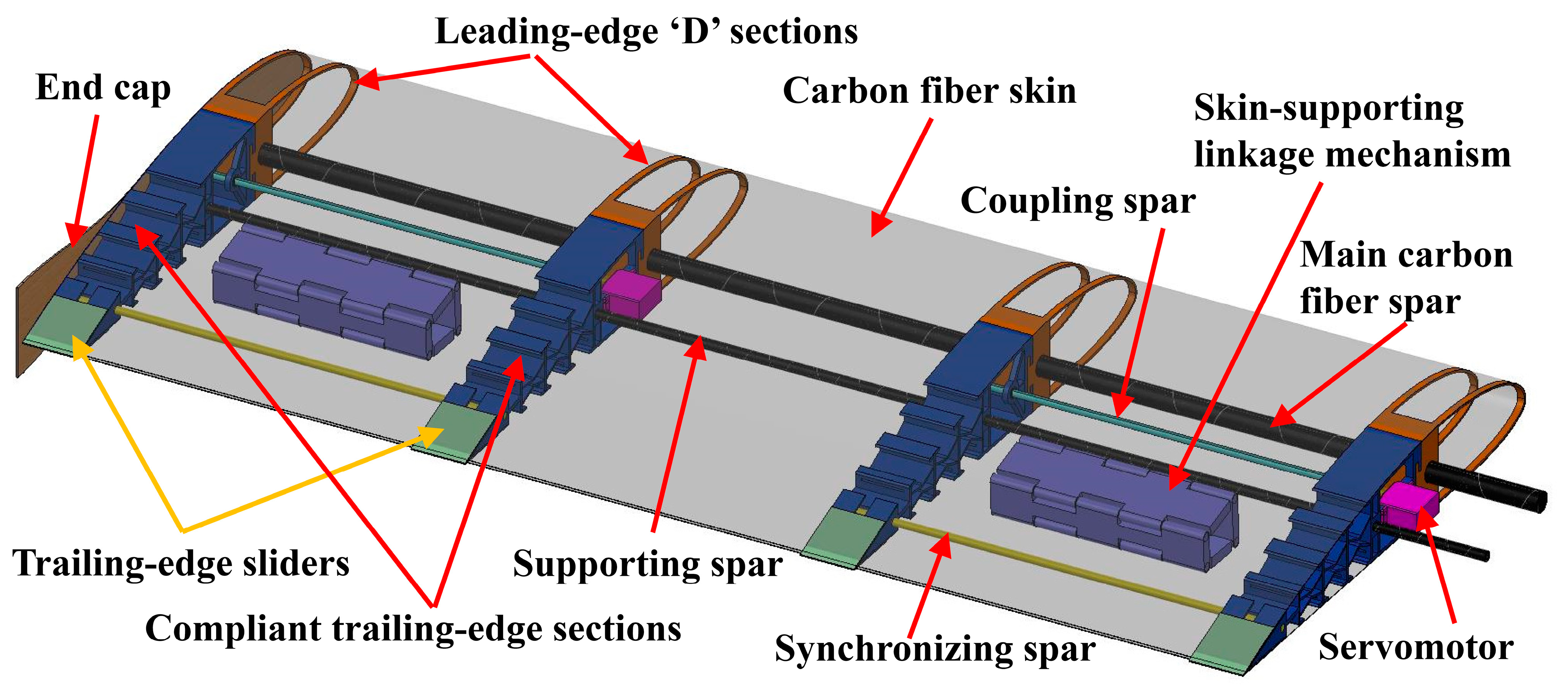
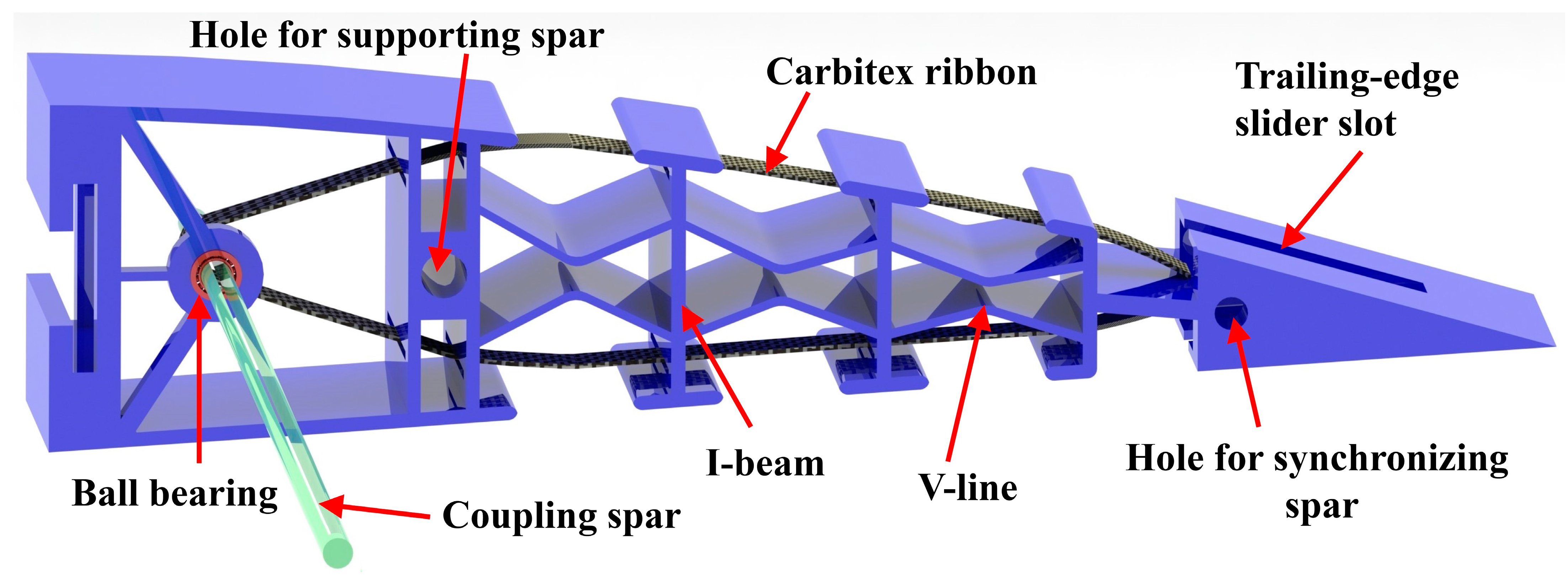
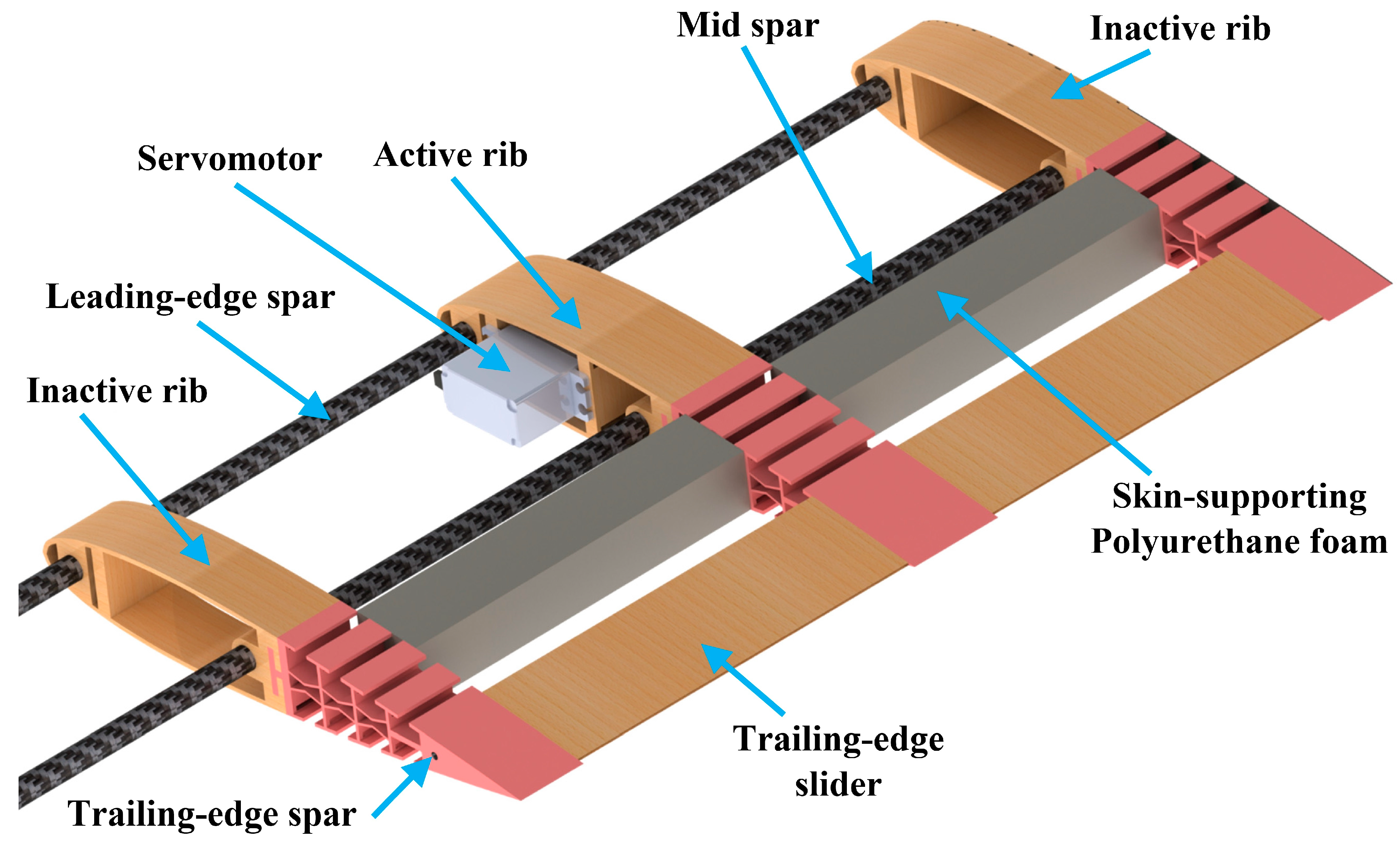
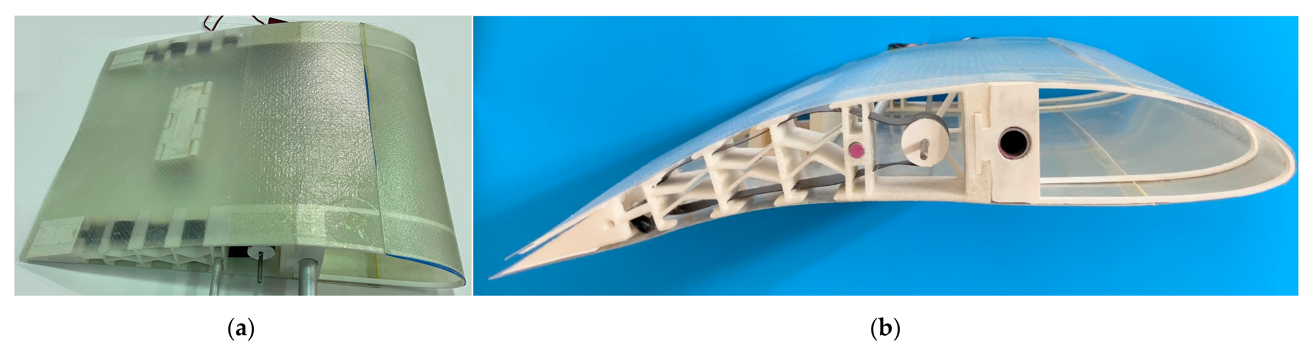
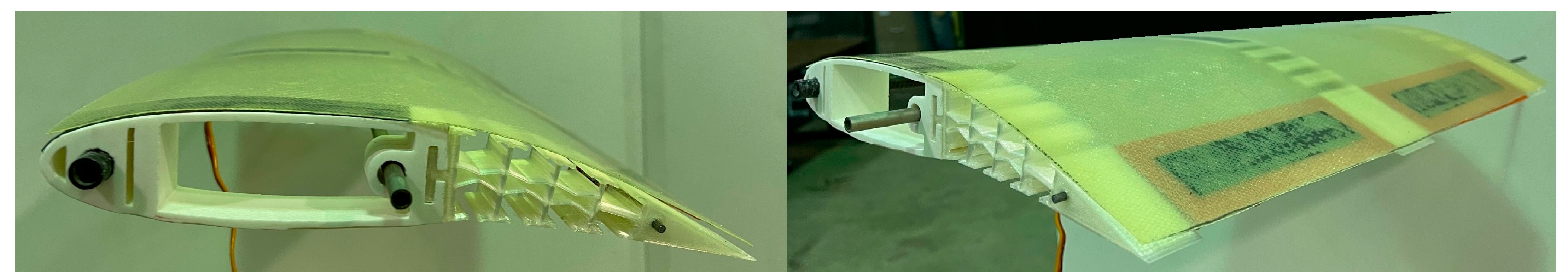
Figure 6 shows the full CAD model of MM-3 with transparent wing and fuselage skin. The fuselage contains a carbon fiber central boom that serves as the main support structure for the wings and the empennage. The fuselage houses batteries and avionics equipment. The main landing gear was mounted to the bottom of the fuselage. The nose cone houses the motor and front landing gear connection. From the tip of the motor to the trailing-edge of the tail, MM-3 has a total length of 1.92 m.

2.2.1. Wing Design

Figure 7 shows the structure of the left camber-morphing wing of MM-3 with transparent skin. The rectangular planform of the wing has a 2.5 m span and a chord length of 0.5 m. The NACA 4415 airfoil was selected based on its high lift profile, relatively simple shape, and ability to adapt dynamically to active cambering. Each wing consists of four active hybrid ribs with leading-edge ‘D’ sections made of Acrylonitrile Butadiene Styrene (ABS) to provide support for the carbon fiber skin. The main carbon fiber spar is inserted through the ‘D’ sections to add extra support and rigidity to the leading-edge. Compliant trailing-edge sections made of Plasticized Copolyamide Thermoplastic Elastomer (PCTPE) are connected to the ‘D’ sections.
The design of the trailing-edge section, shown in Figure 8, is a modified version of the FishBAC design in [10,19]. “V-lines” and “I-beams” replaced the corrugated shape in previous designs to reduce the possibility of buckling along the rib’s central axis when actuated, while still allowing the same amount of camber to be achieved with the available actuation force. PCTPE provides relatively moderate stiffness, resulting in a transversely rigid structure that can support the composite skin and contribute to carrying the expected in-flight aerodynamic loads, while still allowing for bending without a high demand of actuation force.
Two 60 kg servomotors are used in each wing, where each servo actuates two ribs connected via a stainless-steel coupling spar that runs through a flanged ball bearing housed in the trailing-edge section for a smooth rotation. A Carbitex CX6TM ribbon [32] that is connected around the coupling spar using a larger ABS disk runs along the length of the rib through slits in each of the I-beam sections and is fixed at the trailing-edge, as shown in Figure 8. This ribbon converts the rotational motion into a linear actuation that cambers the compliant rib section when the servomotor rotates. A synchronizing spar connects the trailing-edges of each pair of ribs, as shown in Figure 7, to ensure uniform spanwise camber-morphing.
A skin-supporting linkage mechanism 3D-printed of ABS is placed between each pair of ribs to allow for skin sliding during camber-morphing without separation between the skin and the ribs. The skin is a carbon fiber laminated shell comprised of two plies of interwoven fabric. Skin sliding is also facilitated using ABS trailing-edge sliders that are attached to the skin and move chordwise during morphing in a guiding slot in the compliant trailing-edge section (see Figure 7 and Figure 8). Many camber-morphing wing designs in the literature used flexible rubber skin, such as neoprene, to accommodate the increased surface area during camber [10]. The proposed design eliminated the need for such troublesome stretchable skin that can easily sag, wrinkle, warp, or be torn under the expected applied loads, changing flight conditions, and extended use.

2.2.2. Empennage Design

The empennage of MM-3 utilizes a conventional tail configuration consisting of camber-morphing horizontal and vertical stabilizers positioned aft of the fuselage boom to provide trim and stability for the UAV. The horizontal and vertical stabilizers were designed similarly, both featuring NACA 0015 airfoil. The chord lengths of the horizontal and vertical stabilizers were 0.25 m and 0.27 m, respectively. Based on the wing’s AR, the span lengths of the horizontal and vertical stabilizers were 0.83 m and 0.46 m, respectively. Figure 9 shows the structure of one horizontal stabilizer with the skin removed. Each stabilizer features three hybrid ribs, similar to those used in the wing, with two carbon fiber spars for rigidity and stiffness. Each rib is composed of a solid leading-edge section, 50% of chord length, with an integrated PCTPE-compliant trailing-edge section, similar to the design used in the wing’s rib.
The middle rib, detailed in Figure 10, is activated using a servomotor that cambers it via a Carbitex CX6TM ribbon. The actuation compartment, located between the two holes of the carbon fiber spars in the leading-edge section, contains the 25-kg 180-degree servomotor. The two end ribs, shown in Figure 9, are inactive but deform uniformly with the active rib via a trailing-edge spar. Long trailing-edge sliders are placed between the ribs to facilitate skin sliding without separation during camber-morphing. Two polyurethane foam sections located between the ribs are also utilized to ensure that the carbon fiber skin maintains the airfoil shape without separation.

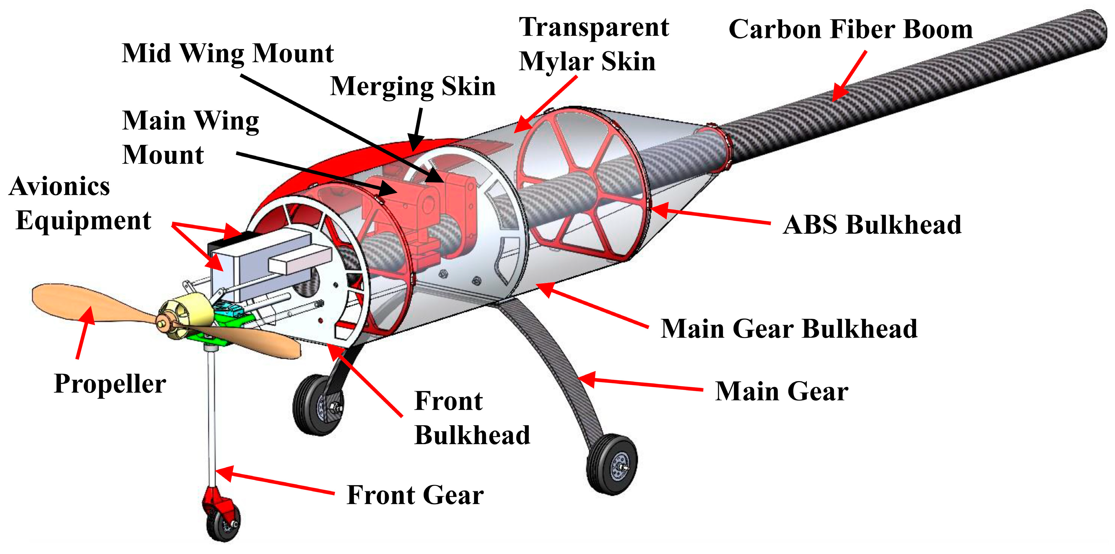
2.2.3. Fuselage Design

Figure 11 shows the structure of MM-3’s fuselage, with the nose cone removed. The tricycle landing gear configuration was selected because it offers good stability during ground operations and prevents ground-looping effects during takeoff. It has two main wheels fixed under the fuselage structure and one wheel at the nose of the aircraft for stability and controllability during taxi. The main landing gear must be positioned slightly aft of the CG and at a certain distance behind the wing’s AC to ensure longitudinal stability. The main gear consists of two 75 mm diameter RC sport wheels fixed to a composite frame made of 16 plies of interwoven carbon fiber to resist the anticipated landing loads. To connect the landing gear frame to the fuselage, an inverted T-bracket was attached to the top face of the frame and fastened between two 6061-T6 aluminum bulkheads. These bulkheads were designed and optimized using topology optimization studies, detailed in Section 3.1.2, which maximize the stiffness-to-weight ratio by removing material from areas that do not experience large stress levels.
The main support structure of MM-3 is a 50.8 mm diameter hollow carbon fiber boom that is used to support the wing and empennage. This central boom runs from the tail attachment through the fuselage and is fixed to the front bulkhead using a flange mount for extra support. The wings are mounted just above the central boom via two independent wing mounts: a main wing mount at the quarter chord and a mid-wing mount at half the chord length. The wing mounts are made of 3D-printed ABS plastic and have threaded heat inserts to prevent cracking of the plastic in local fixture areas. The wing mounts can translate along the main boom, allowing the wings’ position to be fine-tuned for the best location of the AC relative to the CG. Once the final position of the wing is determined, the wing can be permanently mounted to the main boom via two high-strength through-bolts. Physical testing of 3D-printed wing mounts proved that they would not fail when subjected to flight loads. The fuselage skin is a transparent Mylar plastic film that contours to the round profile of the fuselage. The shape of the skin is maintained throughout the length of the fuselage using 3D-printed ABS bulkheads that implement fixturing tabs along the circumference of the bulkhead. The skin is connected to these tabs using silicone O-rings. The fuselage is covered at the forward end with a 3D-printed nose cone and at the aft end with a tail cone tapering to the central boom.

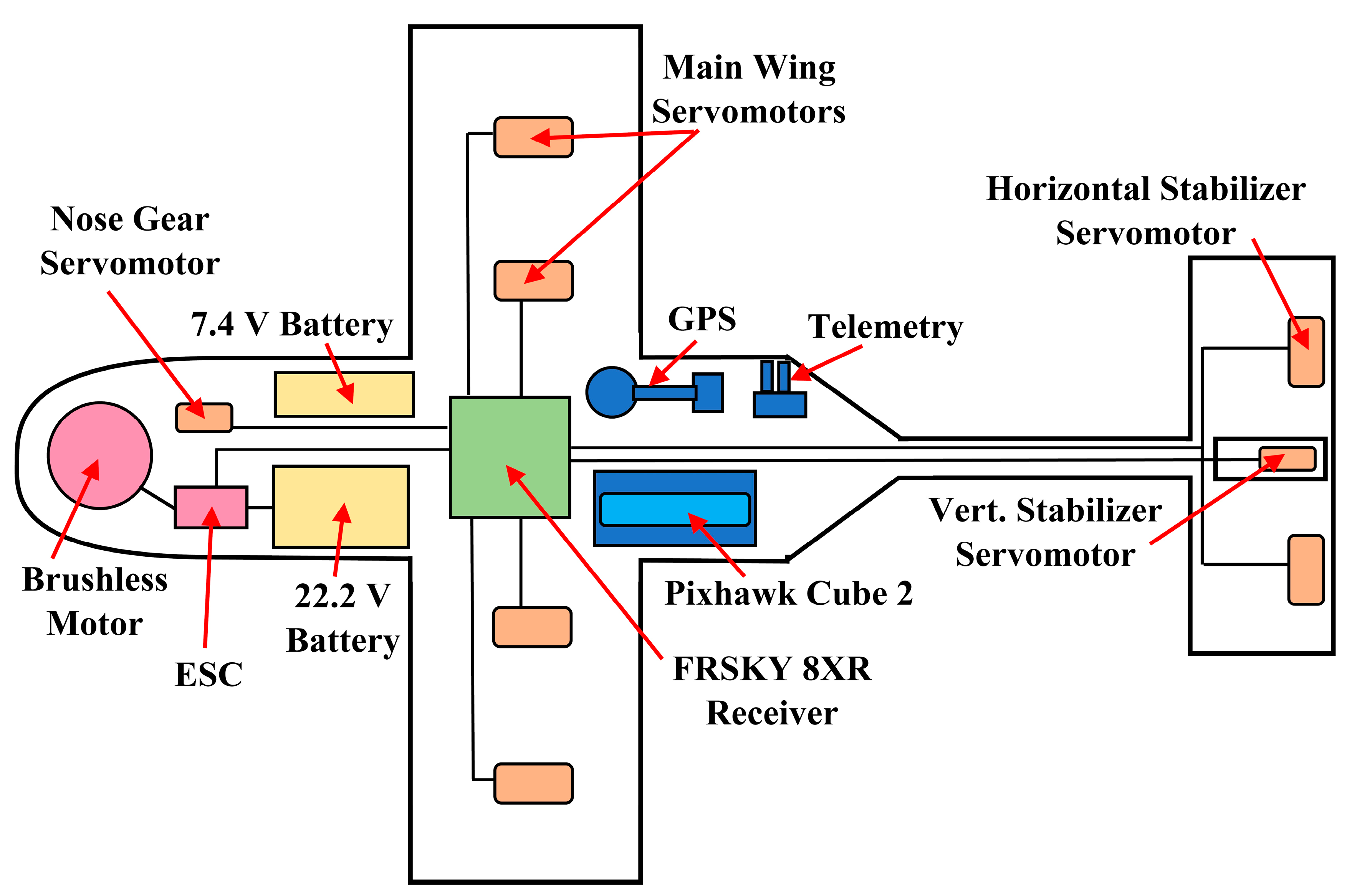
2.2.4. Avionics and Propulsion

MM-3 is an all-electric, propeller-driven UAV capable of projected speeds in excess of 18 m/s. Figure 12 is a representation of the preliminary avionic system on MM-3, which includes propulsion, actuators, and a flight control system. The 5325 X SunnySky Brushless Outrunner Electric Motor was selected and housed in a nose cone. The electric motor was sized based on the estimated maximum takeoff mass of 10 kg and produced a thrust-to-weight ratio greater than 0.44 based on the desired power characteristics. The propeller used was a wooden 43.2 cm diameter with a 20.3 cm fixed pitch, able to produce a thrust-to-weight ratio of about 0.68, which is more than what is required for MM-3’s cruise condition design point. To power the motor and propeller, one 6s 35c 6000 mAh lithium-polymer (LiPo) battery was selected along with one 120 Amp rated Electronic Speed Controller (ESC) by Hobbywing. A secondary 2s 3500 mAh battery by FrSky was selected to power the X8R receiver. The receiver connects to the servomotors that control the wing and tail camber-morphing systems, as well as the ESC and front nose gear servomotor. A Pixhawk microcontroller is connected to the second independent power source to provide information, such as the geolocation of MM-3 via GPS, and flight characteristics, such as altitude and speed, via a telemetry module housed in the front section of the fuselage.

3. Results and Discussion

3.1. Finite Element Analysis (FEA) Studies

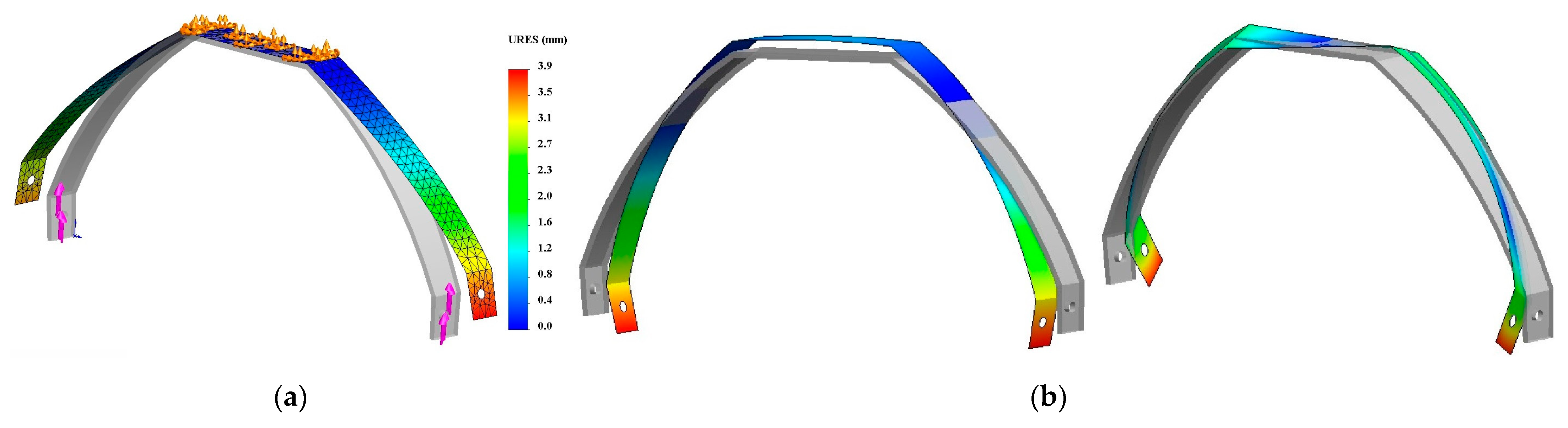
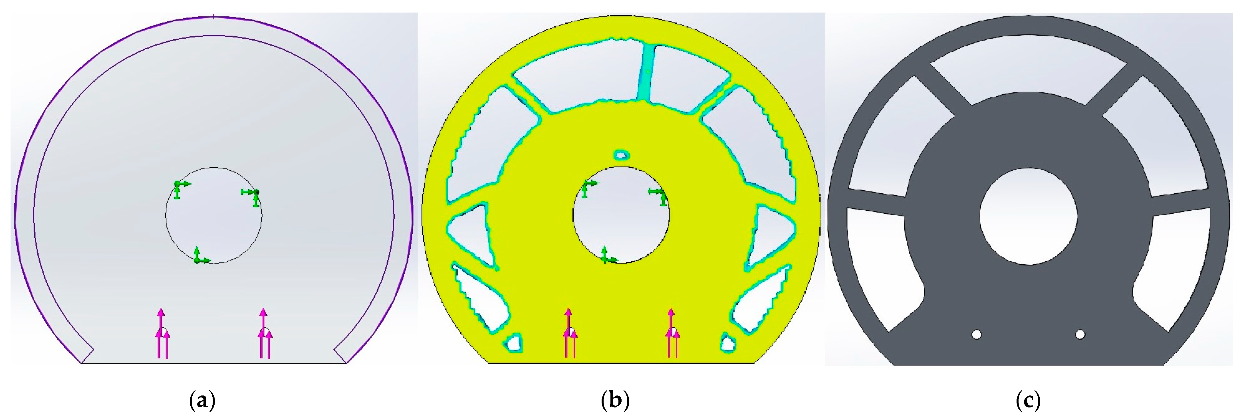
3.1.1. Landing Gear Frame

Static and modal FEA studies were conducted on the carbon fiber landing gear frame to determine the number of plies that would guarantee a suitable factor of safety (FOS) under maximum applied loads. A range of vertical landing speeds was considered, and a vertical load of 70 N was applied in a static study at the two ends of the main landing gear, where the wheels were attached. With the central part of the frame fixed, the applied loads resulted in a maximum displacement of 3.9 mm, as shown in Figure 13a, and a minimum FOS of 9.38. The mesh in all studies was refined until convergence was achieved.
Modal analysis of the frame was also conducted for two reasons: first, to ensure that the anticipated excitation frequency during take-off and landing, which was estimated to be between 20 and 30 Hz, is far from the first natural frequency to avoid resonance, and second, to check if the first significant mode shape results in any twisting of the frame, that would require several plies to have a 45° fiber-orientation angle. A conservative approach was taken in the modal analysis by defining no fixtures. The first non-rigid body (NRB) mode was a bending mode, as shown in Figure 13b, and occurred at a frequency of 70 Hz. The second NRB mode was a twisting mode, also shown in Figure 13b, and occurred at around 170 Hz. Hence, no plies with a 45° fiber-orientation angle were introduced to the composite laminate of the main landing gear frame since resonance is unlikely to happen at the frequency of this twisting vibration mode.

3.1.2. Bulkheads

The main and front bulkhead designs were refined using topology optimization studies in SolidWorks Simulation (version 2020). The goal was to reduce the weight by 30% while maximizing the stiffness-to-weight ratio. In each study, manufacturing constraints were applied such that critical areas of the parts were preserved. Figure 14a shows the outer ring, outlined in purple, representing the preserved area needed to contour the fuselage body. Fixtures and loads were also defined, as in a static study: the central hole, where the main boom will pass through, is fixed, and loads are defined as forces applied on the lower small circular holes. Figure 14b shows the mass reduction plot from the topology optimization study and illustrates which sections of the original shape could be removed for weight reduction. Figure 14c displays the final bulkhead shape, which passed all the following FEA static studies with acceptable FOS (larger than 5).

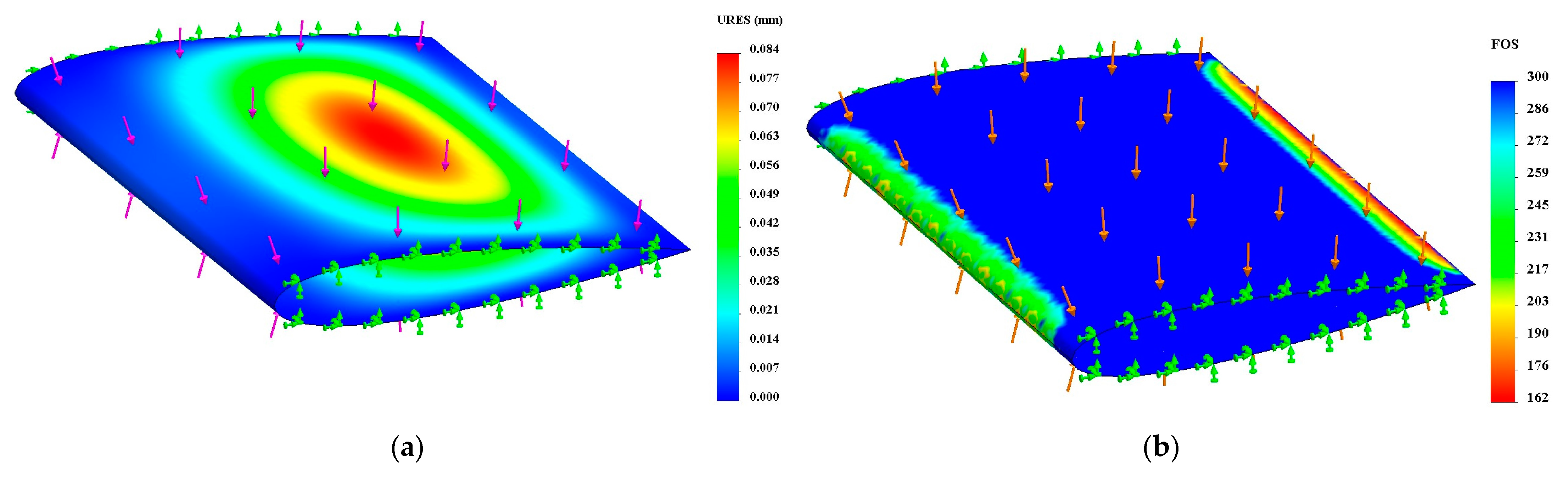
3.1.3. Carbon Fiber Skin

Static FEA studies were performed on the carbon fiber laminated composite skin of the wing and tail. The skin shell had two 0.3 mm thick interwoven carbon fiber plies. The model was restrained where skin would be attached to the ribs. To be conservative, the maximum expected aerodynamic pressure of 495 Pa was applied to the skin. Figure 15a,b show the resultant displacement and minimum FOS distributions, respectively, on the wing skin. It is evident that the maximum displacement is minimal, and the minimum FOS across all plies of the composite is 162, indicating that the skin design is stiff enough to carry the expected loads inflight without failure.

3.1.4. Carbon Fiber Spars

The main wing spar must be stable enough to withstand the aerodynamic forces applied to the wing in flight. FEA static studies were conducted to find the minimum acceptable size and stacking sequence of the spar laminate. A spar with an outer diameter of 13 mm and seven unidirectional carbon fiber plies in a [ 0 2 / 90 / 90 ¯ ] s stacking sequence was found to be capable of carrying the expected applied loads. When clamped as a cantilever and subjected to a weight of 55.5 N (5.66 kg), which is roughly half the weight of MM-3, tip deflection was found to be 5.6 mm, and the minimum FOS was 33. Any commercial carbon fiber spar with similar or stiffer specifications would be suitable for this application. A similar approach was taken in designing the horizontal stabilizer’s leading-edge carbon fiber spar. A 10 mm outer diameter spar was chosen with a layout of 12 unidirectional plies in a [ 0 2 / 45 5 / 45 5 ] ,  stacking sequence. A fixed boundary condition was applied to the face of the spar attached to the boom, while a 15.46 N (1.58 kg) distributed load was applied across the full length of the sectional spar. This resulted in 2.8 mm of displacement at its tip and an overall FOS of 11, indicating a safe and sturdy design.

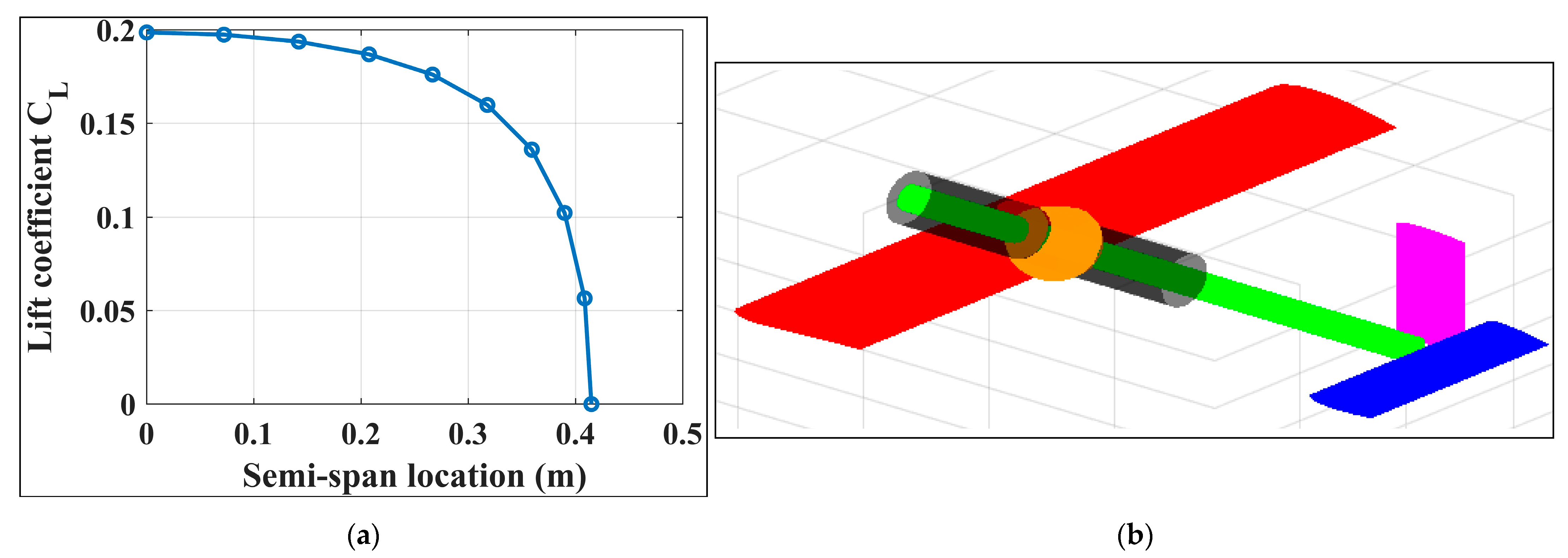
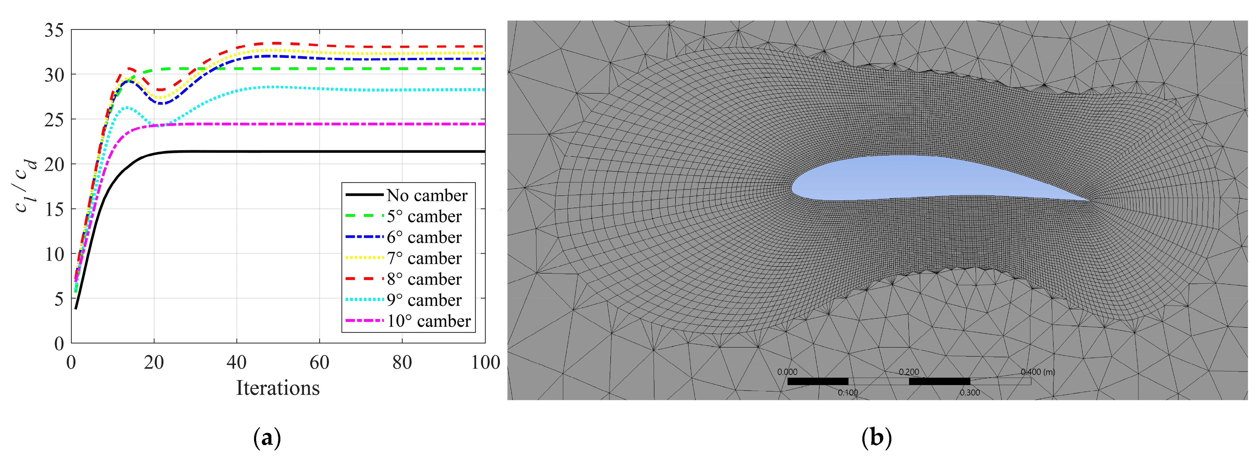
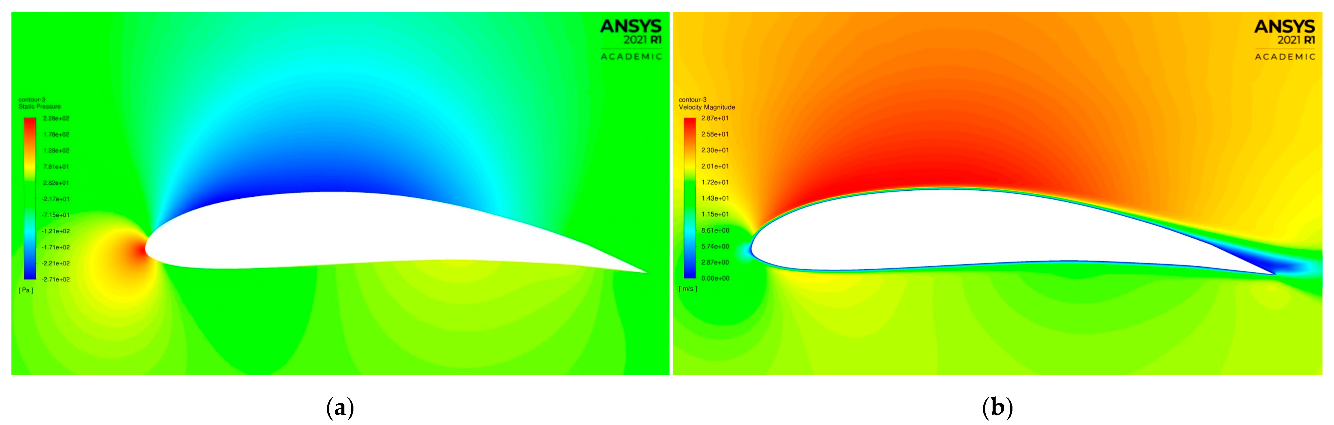
3.2. Computational Fluid Dynamics (CFD) Studies

ANSYS Fluent was used to perform 2D CFD simulations on the wing and tail airfoils as they camber, with the expected aerodynamic flight conditions. The airfoil geometry at various camber angles was imported from SOLIDWORKS to ANSYS, and a rectangular flow domain, 7 m in length × 4 m in height, was created to replicate a wind tunnel experiment. The wing’s NACA 4415 airfoil is designed to camber only down, while the tail horizontal and vertical stabilizers’ NACA 0015 airfoil can camber up or down to generate pitch and yaw moments, respectively. Air properties at sea level were used. The inlet velocity was taken as 20 m/s, and the turbulence intensity was sustained to a default value of 5% for both the inlet and outlet conditions. A no-slip shear condition was applied to the airfoil walls. The flow around the airfoil is considered laminar but transforms to turbulent as the distance from the airfoil boundary increases. The geometry imported to the ANSYS Design Modeler had 200 points along the contour of the airfoil, with cosine spacing. Triangular mesh was used with an element size of 0.1 m along the outer domain boundaries and is highly refined, as it approaches the airfoil’s outer surface with a 0.005 m element size. This local mesh refinement was executed using the inflation feature and edge sizing. A maximum layer count of 40 and a first-layer height of 0.005 m were applied in the boundary layer. Figure 16a shows the convergence plot of NACA 4415 airfoil’s aerodynamic efficiency ( c l / c d ) at 0°, 5°, 6°, 7°, 8°, 9°, and 10° camber. Only twenty-one iterations were needed to achieve convergence. The convergence study led to a mesh with 8569 nodes and 11,388 elements. It can be observed from the figure that the aerodynamic efficiency increases due to the increase in the camber angle, but after a certain degree, it declines. The 8° camber deformation of NACA 4415 resulted in a maximum aerodynamic efficiency of 33.12. The results agree with those reported by Spera [33]. Figure 16b and Figure 17a,b show the mesh as well as the static pressure and velocity distributions around NACA 4415 airfoil at 8° camber. The selected servomotors can apply actuation forces that can morph the wings and tail stabilizers even beyond the desired camber angles, as will be shown in the next section.

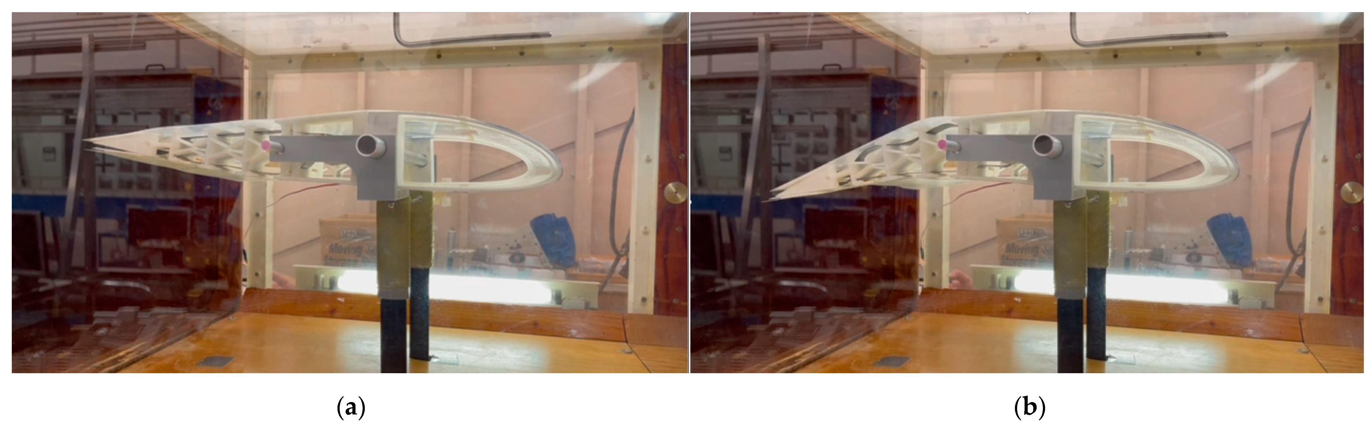
3.3. Proof-of-Concept Testing

The camber-morphing systems in MM-3 wings and tail stabilizers are the most novel ideas in this work. Accordingly, sample wing and tail models were built for proof-of-concept testing. The 3D-printed ABS and PCTPE rib sections were first created and assembled into the spars. The Carbitex ribbon was routed through the compliant trailing-edge section, as mentioned earlier, and was connected to the servomotor. A 3D-printed mold was created for the composite wing skin. This mold was sanded and clear coated before a release agent was applied to it. The composite layup of the skin was made of two interwoven carbon fiber plies. After being released from the mold, the skin was bonded to the leading-edge ‘D’ sections of the ribs, the skin-supporting hinged box, and the trailing-edge sliders. Figure 18 and Figure 19 show the assembled and actuated wing and tail stabilizer proof-of-concept models, respectively. Actuation tests showed that the composite skin slides smoothly and cambered the airfoil up to 20°, with no wrinkling or warping during camber-morphing. The trailing-edge sliders also translated in their slots smoothly, with minimal resistance. The three hybrid ribs cambered uniformly without buckling. Wind tunnel tests were also conducted on the proof-of-concept models, as shown in Figure 20. At wind speeds as high as 35 m/s, the wing model successfully achieved up to a 20° camber angle, proving that the selected servomotors can provide even more than the required actuation force to morph the model. The test also proved that the skin sliding concept works smoothly while the skin carries the applied aerodynamic loads without any wrinkling.

4. Summary and Conclusions

This paper presents the design and analysis of MataMorph-3, an innovative fully morphing UAV with camber-morphing wings and tail stabilizers. This UAV has no discrete flight control surfaces, such as elevator, rudder, or ailerons. The proposed design features the idea of sliding skin, which can enable the utilization of stiff and sturdy skin without wrinkling, sagging, or warping problems experienced in many previous skin designs in the literature. This was realized in the wing by integrating trailing-edge sliders in the compliant trailing-edge sections of the hybrid ribs and adding skin-supporting linkage mechanisms between the ribs. A similar design was utilized in the tail’s horizontal and vertical stabilizers, with trailing-edge sliders spanning the whole distance between the ribs. Both versions of the skin sliding design proved effective in the manufactured proof-of-concept models tested in the wind tunnel. The selected servomotors were capable of achieving camber angles larger than the desired angles at speeds higher than the designed cruise speed. The paper also presented details on the computer application created to aid in the preliminary design and sizing process, and computational FEA and CFD studies that helped in refining and validating the selected design parameters. A fuselage design that enables fine-tuning of the wing location for improved stability, along with an avionics and propulsion system, has also been detailed. MataMorph-3 is a contribution to morphing UAV research and technology that tackles the challenging skin design problem with an innovative sturdy sliding skin design, eliminating the need for stretchable skin.

Author Contributions

Conceptualization, all authors; methodology, all authors; software, all authors; validation, P.L.B., J.S.K., L.J.F. and B.M.E.; formal analysis, P.L.B., J.S.K., L.J.F. and B.M.E.; investigation, all authors; resources, P.L.B., J.S.K., L.J.F. and B.M.E.; data curation, all authors; writing—original draft preparation, P.L.B., J.S.K., L.J.F. and B.M.E.; writing—review and editing, P.L.B.; visualization, all authors; supervision, P.L.B.; project administration, P.L.B., J.S.K., L.J.F. and B.M.E.; funding acquisition, P.L.B. All authors have read and agreed to the published version of the manuscript.

Funding

This research received no external funding.

Institutional Review Board Statement

Not Applicable.

Informed Consent Statement

Not Applicable.

Data Availability Statement

The data presented in this study are available on request from the corresponding author.

Acknowledgments

This work was done by the fifth cohort of “Smart Morphing Wing” research-based senior design project (SDP) at California State University, Northridge (CSUN). The following members are acknowledged: Abanob Samaan, Charles Acuna, David Javoorian, Anthony Ghaoui, and Craig Stevens. The authors also acknowledge Professor Vinicius Sauer, the Mechanical Engineering Department, and the Instructionally Related Activities (IRA) grant at CSUN.

Conflicts of Interest

The authors declare no conflict of interest.

References

  1. Valasek, J. Morphing Aerospace Vehicles and Structures, 2nd ed.; John Wiley & Sons: Chichester, UK, 2012. [Google Scholar]
  2. Spillman, J.J. The use of variable camber to reduce drag, weight and costs of transport aircraft. Aeronaut. J. 1992, 96, 1–9. [Google Scholar] [CrossRef]
  3. Barbarino, S.; Bilgen, O.; Ajaj, R.M.; Friswell, M.I.; Inman, D.J. A review of morphing aircraft. J. Intell. Mater. Syst. Struct. 2011, 22, 823–877. [Google Scholar] [CrossRef]
  4. Gomez, J.C.; Garcia, E. Morphing unmanned aerial vehicles. Smart Mater. Struct. 2011, 20, 103001. [Google Scholar] [CrossRef]
  5. Amendola, G.; Dimino, I.; Magnifico, M.; Pecora, R. Distributed actuation concepts for a morphing aileron device. Aeronaut. J. 2016, 120, 1365–1385. [Google Scholar] [CrossRef]
  6. Li, D.; Zhao, S.; Da Ronch, A.; Xiang, J.; Drofelnik, J.; Li, Y.; Zhang, L.; Wu, Y.; Kintscher, M.; Monner, H.P.; et al. A review of modelling and analysis of morphing wings. Prog. Aerosp. Sci. 2018, 100, 46–62. [Google Scholar] [CrossRef] [Green Version]
  7. Tidwell, Z.; Joshi, S.; Crossley, W.; Ramakrishnan, S. Comparison of morphing wing strategies based upon aircraft performance impacts. In Proceedings of the 45th AIAA/ASME/ASCE/AHS/ASC Structures, Structural Dynamics & Materials Conference, Palm Springs, CA, USA, 19–22 April 2004; p. 1722. [CrossRef] [Green Version]
  8. Bishay, P.L.; Burg, E.; Akinwunmi, A.; Phan, R.; Sepulveda, K. Development of a new span-morphing wing core design. Designs 2019, 3, 12. [Google Scholar] [CrossRef] [Green Version]
  9. Ajaj, R.M.; Jankee, G.K. The Transformer aircraft: A multimission unmanned aerial vehicle capable of symmetric and asymmetric span morphing. Aerosp. Sci. Technol. 2018, 76, 512–522. [Google Scholar] [CrossRef] [Green Version]
  10. Schlup, A.; Bishay, P.L.; Mclennan, T.; Barajas, C.; Talbian, B.; Thatcher, G.; Flores, R.; Perez-Norwood, J.; Torres, C.; Kibert, K.; et al. MataMorph 2: A new experimental UAV with twist-morphing wings and camber-morphing tail stabilizers. In Proceedings of the AIAA Scitech 2021 Forum, Virtual, 11–15 & 19–21 January 2021; p. 584. [Google Scholar] [CrossRef]
  11. Parancheerivilakkathil, M.S.; Haider, Z.; Ajaj, R.M.; Amoozgar, M. A polymorphing wing capable of span extension and variable pitch. Aerospace 2022, 9, 205. [Google Scholar] [CrossRef]
  12. Fasel, U.; Keidel, D.; Baumann, L.; Cavolina, G.; Eichenhofer, M.; Ermanni, P. Composite additive manufacturing of morphing aerospace structures. Manuf. Lett. 2020, 23, 85–88. [Google Scholar] [CrossRef]
  13. Cees, B.; Massey, K.; Abdullah, E.J. Wing morphing control with shape memory alloy actuators. J. Intell. Mater. Syst. Struct. 2013, 24, 879–898. [Google Scholar] [CrossRef]
  14. Majid, T.; Jo, B.W. Comparative aerodynamic performance analysis of camber morphing and conventional Airfoils. Appl. Sci. 2021, 11, 10663. [Google Scholar] [CrossRef]
  15. Joo, J.J.; Marks, C.R.; Zientarski, L.; Culler, A.J. Variable camber compliant wing-design. In Proceedings of the 23rd AIAA/AHS Adaptive Structures Conference, Kissimmee, FL, USA, 5–9 January 2015; p. 1050. [Google Scholar] [CrossRef]
  16. Bishay, P.L.; Finden, R.; Aslanpour, D.; Lopez, E.; Alas, C.; Recinos, S.; Flores, D.; Gonzalez, E.; Popa, R. Development of an SMA-based camber morphing UAV tail core design. Smart Mater. Struct. 2019, 28, 075024. [Google Scholar] [CrossRef]
  17. Fincham, J.; Friswell, M. Aerodynamic optimisation of a camber morphing aerofoil. Aerosp. Sci. Technol. 2015, 43, 245–255. [Google Scholar] [CrossRef] [Green Version]
  18. Yokozeki, T.; Sugiura, A.; Hirano, Y. Development and wind tunnel test of variable camber morphing wing. In Proceedings of the 22nd AIAA/ASME/AHS Adaptive Structures Conference, National Harbor, MD, USA, 13–17 January 2014; p. 1261. [Google Scholar] [CrossRef]
  19. Woods, B.K.S.; Friswell, M.I. Preliminary investigation of a fishbone active camber concept. Smart Mater. Adapt. Struct. Intell. Syst. Am. Soc. Mech. Eng. 2012, 45103, 555–563. [Google Scholar] [CrossRef]
  20. Jo, B.W.; Majid, T. Aerodynamic analysis of camber morphing airfoils in transition via computational fluid dynamics. Biomimetics 2022, 7, 52. [Google Scholar] [CrossRef]
  21. Ott, V.; Keidel, D.; Kölbl, M.; Ermanni, P. Investigation of an adaptive, hinge-less, and highly shear stiff structure for morphing skins. J. Intell. Mater. Syst. Struct. 2020, 31, 445–456. [Google Scholar] [CrossRef]
  22. Chanzy, Q.; Keane, A.J. Analysis and experimental validation of morphing UAV wings. Aeronaut. J. 2018, 122, 390–408. [Google Scholar] [CrossRef] [Green Version]
  23. Ahmad, D.; Ajaj, R.M. Multiaxial mechanical characterization of latex skin for morphing wing application. Polym. Test. 2022, 106, 107408. [Google Scholar] [CrossRef]
  24. Thill, C.L.; Etches, J.; Bond, I.; Potter, K.; Weaver, P. Morphing skins. Aeronaut. J. 2008, 112, 117–139. [Google Scholar] [CrossRef]
  25. Rediniotis, O.K.; Wilson, L.N.; Lagoudas, D.C.; Khan, M.M. Development of a shape-memory-alloy actuated biomimetic hydrofoil. J. Intell. Mater. Syst. Struct. 2002, 13, 35–49. [Google Scholar] [CrossRef]
  26. Yu, A.; Xi, F.; Moosavian, A.; Li, B. Design of a sliding morphing skin with segmented rigid panels. J. Aircr. 2018, 55, 1985–1994. [Google Scholar] [CrossRef]
  27. Yu, A.; Xi, F.; Ghaemi, H.; Li, B. Modeling of a complete morphing mechanism covered by a paneled morphing skin. J. Mech. Robot. 2021, 13, 021003. [Google Scholar] [CrossRef]
  28. Fereidooni, A.; Marchwica, J.; Leung, N.; Mangione, J.; Wickramasinghe, V. Development of a hybrid (rigid-flexible) morphing leading-edge equipped with bending and extending capabilities. J. Intell. Mater. Syst. Struct. 2020, 32, 1024–1037. [Google Scholar] [CrossRef]
  29. Sadraey, M.H. Aircraft Design: A Systems Engineering Approach; John Wiley & Sons: Chichester, UK, 2013. [Google Scholar]
  30. Glīzde, N. Wing and engine sizing by using the matching plot technique. Transp. Aerosp. Eng. 2017, 5, 48–59. [Google Scholar] [CrossRef] [Green Version]
  31. Keane, A.; Sóbester, A.; Scanlan, J. Small Unmanned Fixed-Wing Aircraft Design: A Practical Approach; John Wiley & Sons: Hoboken, NJ, USA, 2017. [Google Scholar]
  32. Available online: https://www.carbitex.com/ (accessed on 1 July 2022).
  33. Spera, A.D. Models of lift and drag coefficients of stalled and unstalled airfoils in wind turbines and wind tunnels. Available online: https://ntrs.nasa.gov/api/citations/20090001311/downloads/20090001311.pdf (accessed on 9 June 2022).
Figure 1. MataMorph-3 Design and Sizing application.
Aerospace 09 00382 g001
Figure 2. MataMorph-3 Design and Sizing application flowchart.
Aerospace 09 00382 g002
Figure 3. (a) Constraint Diagram input parameters, and (b) Tail Sizing input parameters.
Aerospace 09 00382 g003
Figure 4. (a) Tail LLT input parameters, and (b) CG Calculator input parameters.
Aerospace 09 00382 g004
Figure 5. (a) Sample lift distribution on MM3’s horizontal tail, and (b) Center of gravity display.
Aerospace 09 00382 g005
Figure 6. Full CAD model of MataMorph-3 (MM-3).
Aerospace 09 00382 g006
Figure 7. CAD model of the MM-3 wing.
Aerospace 09 00382 g007
Figure 8. MM-3’s compliant trailing-edge section.
Aerospace 09 00382 g008
Figure 9. MM-3’s horizontal stabilizer.
Aerospace 09 00382 g009
Figure 10. Horizontal stabilizer’s active rib.
Aerospace 09 00382 g010
Figure 11. MM-3’s fuselage assembly.
Aerospace 09 00382 g011
Figure 12. MM-3’s avionics and wiring diagram.
Aerospace 09 00382 g012
Figure 13. (a) Displacement of main landing gear in static study; (b) Main landing gear’s 1st (left, 70 Hz) and 2nd (right, 170 Hz) NRB mode shapes.
Aerospace 09 00382 g013
Figure 14. (a) Original part with applied manufacturing constraints, (b) Mass reduction plot from topology optimization study, (c) Optimized shape used in final model.
Aerospace 09 00382 g014
Figure 15. Wing skin plots (a) resultant displacement; (b) Minimum factor of safety across all plies.
Aerospace 09 00382 g015
Figure 16. (a) Convergence plot of NACA 4415’s c l / c d at various camber angles; (b) Local mesh around NACA 4415 (8° camber).
Aerospace 09 00382 g016
Figure 17. (a) Static pressure and (b) velocity distribution around NACA 4415 at 8° camber and zero angle of attack.
Aerospace 09 00382 g017
Figure 18. (a) assembled wing model; (b) cambered wing model.
Aerospace 09 00382 g018
Figure 19. Two views for the assembled and camber-morphed tail stabilizer model.
Aerospace 09 00382 g019
Figure 20. Wind tunnel testing: (a) uncambered model, (b) cambered at 35 m/s airspeed.
Aerospace 09 00382 g020
Publisher’s Note: MDPI stays neutral with regard to jurisdictional claims in published maps and institutional affiliations.

