Article

Constrained Motion Planning of 7-DOF Space Manipulator via Deep Reinforcement Learning Combined with Artificial Potential Field

1
College of Astronautics, Nanjing University of Aeronautics and Astronautics, Nanjing 211106, China
2
Shanghai Aerospace Control Technology Institute, Shanghai 201109, China
3
Shanghai Key Laboratory of Aerospace Intelligent Control Technology, Shanghai 201109, China
*
Author to whom correspondence should be addressed.
Aerospace 2022, 9(3), 163; https://doi.org/10.3390/aerospace9030163
Submission received: 28 February 2022 / Revised: 14 March 2022 / Accepted: 15 March 2022 / Published: 17 March 2022
(This article belongs to the Special Issue Recent Advances in Spacecraft Dynamics and Control)

Abstract

:
During the on-orbit operation task of the space manipulator, some specific scenarios require strict constraints on both the position and orientation of the end-effector, such as refueling and auxiliary docking. To this end, a novel motion planning approach for a space manipulator is proposed in this paper. Firstly, a kinematic model of the 7-DOF free-floating space manipulator is established by introducing the generalized Jacobian matrix. On this basis, a planning approach is proposed to realize the motion planning of the 7-DOF free-floating space manipulator. Considering that the on-orbit environment is dynamical, the robustness of the motion planning approach is required, thus the deep reinforcement learning algorithm is introduced to design the motion planning approach. Meanwhile, the deep reinforcement learning algorithm is combined with artificial potential field to improve the convergence. Besides, the self-collision avoidance constraint is considered during planning to ensure the operational security. Finally, comparative simulations are conducted to demonstrate the performance of the proposed planning method.

1. Introduction

In the last few decades, aerospace technology has developed rapidly, and the on-orbit operation tasks have become more and more complicated. Although most of those tasks can be carried out by astronauts, the extravehicular activities are unaffordable and dangerous, especially when the operating subjects are not cooperative. With the development of automatic control, microelectronics, and other technologies, manipulators have been able to replace humans to complete tasks, such as moving objects [1] and precise operations [2]. In this context, the space manipulator has attracted increasing attention from researchers in the fields of non-cooperative target capture [3], combined spacecraft control [4], space station maintenance [5,6], large-scale space structure assembling [7], and other on-orbit operations. Dynamic modeling, motion planning, and trajectory tracking control of robotic arms are critical to mission success [8]. Due to the dexterity brought by the humanoid arm structure, the 7-DOF free-floating space manipulator is one of the most widely used manipulators in aerospace engineering. However, the high degree of freedom means that the dynamic model of the manipulator is more complex, which also brings great challenges to motion planning, especially when there are complex constraints. Therefore, the constrained motion planning of the 7-DOF free-floating space manipulator has important theoretical and applied values.
Some specific operation tasks, e.g., refueling and auxiliary docking, require strict constraints of the position and orientation of the space manipulator end-effector, thus a large amount of studies have been conducted to solve the space manipulator end-effector position and orientation alignment motion planning problem in recent years. To deal with the dynamic singularities limits in motion planning of the 7-DOF free-floating space robot, Wang proposed a constrained differential evolution (DE) scheme with premature handling strategy, which can move the end-effector to the target pose while minimizing disturbance on the base [9]. The motion planning goal was also achieved by Liu through particle swarm optimization combined with differential evolution [10]. To address the motion planning of the robotic arm mounted on the free-floating unmanned spacecraft, Rybus proposed an active-set algorithm-based planning method, and obtained a collision-free path of the arm, which can move the gripper to the desired position and orientation and maneuver the spacecraft to the desired attitude [11]. Jin developed a method based on damped least squares and feedback compensation to avoid the dynamic singularities because of the inverse kinematics during the motion planning of high-degree-of-freedom space robot. The base attitude disturbance and moving time constraints were considered and the chaotic particle swarm optimization was employed to solve the multi-objective optimization problem [12]. Zhang considered the attitude disturbance of the base caused by the joint motion of the space manipulator and the collision between the end-effector and the target, and proposed a preimpact trajectory planning method for the non-redundant free-floating space manipulator based on the particle swarm optimization, which allows the end-effector to move to the desired capture pose with minimum base disturbance [13]. Lu formulated the motion planning problem of the 10-DOF free-floating space manipulator as a constrained convex quadratic programming problem, thereby achieved the spacecraft attitude stabilization and the end-effector trajectory tracking simultaneously [14]. Similarly, Misra also solved the 10-DOF free-floating space manipulator trajectory planning problem by formulating it as a convex optimization problem, in addition to minimizing the disturbance on base, the obstacle avoidance was also considered in his works [15,16]. Lu proposed a Cartesian motion planning algorithm for the free-floating space manipulator, and designed four optimization objective functions for different control requirements, thus achieving the end-effector position and orientation alignment and minimized the disturbance on base [17]. It can be seen that the present methods for solving the space manipulator end-effector position and orientation alignment motion planning problem are mainly based on heuristic algorithms and optimization methods; their common shortcoming is that the planning method is very sensitive to the initial configuration and the desired pose of the space manipulator, which means a new planning process must be performed when the initial configuration or the desired pose changed. Meanwhile, when measurement error occurs during motion, it may lead to the failure of planning. Considering that the real operation environment on orbit is complicated and dynamical, the robustness is necessary for the motion planning approach. It should be noted that the definition of the position and orientation of the space manipulator end-effector in this paper is different from that in most of the above references. Since the mission scenarios, such as refueling and auxiliary docking, which are considered in this paper have no special requirement on the last joint of the space manipulator, the rotation of the end-effector around its main axis is not considered during planning.
Artificial potential field (APF) has been widely used in obstacle avoidance of manipulators since it was first proposed by Khatib in 1986 [18]. Liu proposed a motion planning method based on improved APF to enable the space manipulator pass through the window-shaped obstacle. While the repulsive force generated by the repulsive potential field of obstacles is set to act only on the end-effector, which leads to no guarantee of collision-free between other parts of the manipulator and obstacles [19]. To properly handle the interaction between the repulsive potential field of obstacle and the entire manipulator, some studies have focused on the selection of the point of action. Wang selected the action point of repulsive force on the joint closest to the obstacle [20]. Li described the repulsive force acting on the manipulator by selecting several evaluation points on the entire manipulator [21]. The above motion planning methods are all carried out in Cartesian space, and inverse kinematics solutions are required at each planning step. However, the inverse kinematics of manipulator is a complicated multi-solution problem, which may result in discontinuous joint angle path. Zhang proposed an improved APF method for six-DOF serial robot motion planning to address this problem, the planning was performed directly in the joint space to avoid the inverse kinematics solving [22]. Although this method no longer needs to solve the inverse kinematics, it requires substantial traversal in each step and is easy to fall into a local minimum; meanwhile, the robustness of this method is poor.
Since the artificial intelligence approach have strong learning and reasoning abilities [23], it has been introduced by scholars to improve the robustness of the space manipulator motion planning and control methods [24]. Among them, the reinforcement learning is one of the most widely used approaches in manipulator path planning [25]. Yan used soft Q-learning to solve the motion planning and control problem of free-floating space robots to capture targets [26]. Liang designed a motion control model for space robot based on the actor-critic algorithm, which can move the end-effector to the desired position and orientation [27]. In contrast, the deep deterministic policy gradient (DDPG) algorithm is more commonly used in manipulator path planning problems due to its good convergence and the outstanding ability to address the continuous action space [28]. For ground manipulators, some scholars use DDPG algorithm to solve the point-to-point path planning problem [29,30,31,32]. However, their planning goals are relatively simple, which also did not consider complex motion constraints. For space manipulators, Du presented a “pre-training” skill to improve the learning efficiency of DDPG in space manipulator motion planning [33]. Hu considered multi constraints including safety performance, coupling disturbance and path length, and proposed a multi-constrained reward deep deterministic policy gradient algorithm for the motion planning of a free-floating space robot, by which the end-effector can be moved to the desired position while avoiding obstacles [34]. In addition, the motion planning problem of free-floating dual-arm space manipulator was also researched by some scholars. Wu solved the motion planning problem of dual-arm space robot by using DDPG [35]. Based on his work, Li considered complicated constraints, thereby made the path planning approach of dual-arm space manipulator closer to the actual engineering [36]. In aforesaid works, only the position of the end-effector was planned, and the degrees of freedom of the manipulator are relatively low, which limits the application range of those works. However, the consideration of high-degree-of-freedom space manipulator model and complex planning goals will make the DDPG algorithm difficult to converge.
In this paper, a novel motion planning approach base on deep reinforcement learning combined with artificial potential field is proposed to solve the 7-DOF space manipulator motion planning problem considering the end-effector position and orientation alignment. Because the base of the space manipulator is usually in a free-floating state when performing on-orbit operation task, there exist strong coupling effect between the base and the manipulator links. The generalized Jacobian matrix proposed by Umetani and Yoshida [37] is introduced to describe the kinematic characteristics of the 7-DOF free-floating space manipulator. Considering the complicated and dynamical environment in space, robustness is necessary for the motion planning algorithm, thus the DDPG algorithm is adopted to establish the algorithm framework of the proposed planning approach. The artificial potential field is utilized to improve the convergence of DDPG for planning missions with complex goal. Furthermore, the self-collision avoidance constraint is considered during planning process to ensure the operational security.
The rest of this paper is organized as follows: in Section 2, a preliminary, including the kinematics of 7-DOF free-floating space manipulator, the principle of DDPG algorithm, and the artificial potential field, is introduced. The motion planning algorithm design is elaborated in Section 3. Section 4 shows the simulation results and discussion. Additionally, the conclusions of this work are given in Section 5.

2. Preliminary

In this paper, the angular velocities of the manipulator joints are taken as the planning object, so the kinematic model of the 7-DOF space manipulator is indispensable. Meanwhile, the DDPG algorithm and the artificial potential field are the theoretical bases of the proposed motion planning approach. Therefore, in this section, the kinematics of the 7-DOF free-floating space manipulator are established, and a brief introduction of DDPG algorithm and artificial potential field is given.

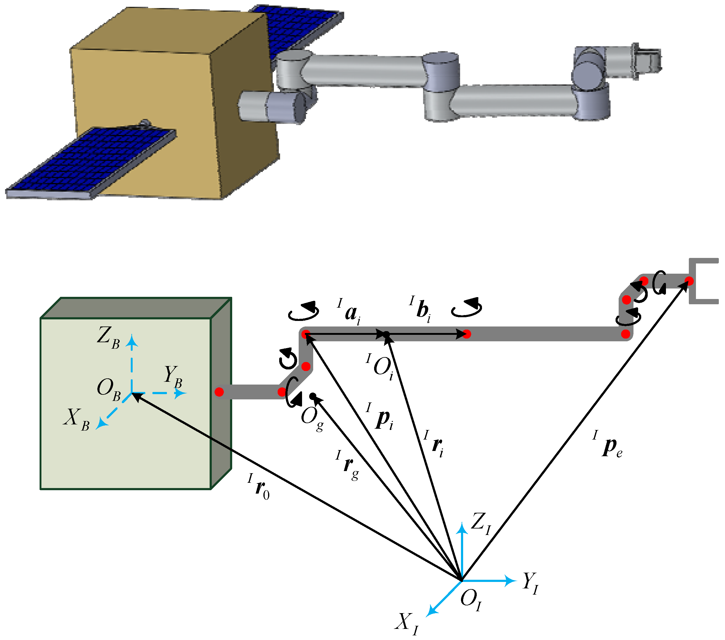
2.1. Kinematic Modeling of 7-DOF Free-Floating Space Manipulator

The configuration and kinematic relationship of the 7-DOF space manipulator considered in this paper is shown in Figure 1. The dynamic parameters are listed in Table 1. Among them, link 1 is an offset link which is fixedly connected to the base to prevent link 2 and link 3 from colliding with the base. Different from ground manipulators, there exist complex coupling effects between the free-floating base and the links of the space manipulator, so the commonly used kinematic modeling approaches are inapplicable to space manipulators. To this end, the generalized Jacobian matrix is introduced to establish the kinematic model of the 7-DOF space manipulator.
Define joint j as the joint between link i − 1 and link i, and joint 1 is defined as the joint between the base and link 1, which is a fixed joint as mentioned before. According to the geometric topological relation shown in Figure 1, the mass center position of each link can be described as follows:
r I i = r I 0 + j = 1 i a I j + j = 0 i 1 b I j
where the superscript “I” denotes the corresponding vector is represented in the inertial coordinate system. r I 0 and r I i are the radius vectors of the mass center of the base and link i ( i [ 1 , 8 ] ), respectively. a I j denotes the vector from joint j to the mass center of link j, and b I j is the vector from the mass center of link j to joint j + 1. It should be noted that b I 0 denotes the vector from mass center of the base to the connected point between the base and link 1.
Take the derivative of r I i with respect to time, and the velocity of each link can be obtained as follows:
v I i = v I 0 + ω I 0 × ( r I i r I o ) + j = 1 i z I j × ( r I i p I j ) ϕ ˙ j
where v I 0 and ω I 0 denote the linear velocity and angular velocity of the base, respectively; v I i is the velocity of the mass center of link i, z I j is the direction vector of the angular velocity of joint j; p I j and ϕ ˙ j are the position vector and angular velocity magnitude of joint j, respectively. Noted that the angular velocity of joint 1 is zero.
The angular velocity of link i can be described as follows:
ω I i = ω I 0 + j = 1 i z I j ϕ ˙ j
From Equations (1)–(3) the linear velocity and angular velocity of the end-effector can be obtained as follows:
{ v I e = v I 0 + ω I 0 × ( p I e r I o ) + j = 1 n z I j × ( p I e p I j ) ϕ ˙ j ω I e = ω I 0 + j = 1 n z I j ϕ ˙ j
where v I e and ω I e denote the linear velocity and angular velocity of the end-effector, respectively. p I e is the position vector of the end-effector. Equation (4) can be transformed as the following form:
[ v I e ω I e ] = J 0 [ v I 0 ω I 0 ] + J ϕ   ϕ ˙
where ϕ ˙ = ( ϕ ˙ 1 , ϕ ˙ 2 ϕ ˙ 8 ) T , and J 0 and J ϕ are the Jacobian matrices from the joint space to the inertial space with the following definition:
J 0 = [ E 3 , p ˜ 0 e O , E 3 ] J ϕ = [ z I 1 × ( p I e p I 1 ) , , z I n × ( p I e p I n ) z I 1 , z I 2 , , z I n ]
where E 3 denotes 3 × 3 identity matrix and p 0 e k = p e k r 0 . Additionally, for a vector e = [ e x , e y , e z ] , the operator e ˜ is defined as:
e ˜ = [ 0 e z e y e z 0 e x e y e x 0 ]
For the manipulator on ground, the linear velocity and angular velocity of the base are both zero, thus Equation (5) is sufficient to describe the kinematic characteristics. However, for the space manipulator, the joint angular velocity is coupled with the linear velocity and angular velocity of the base, so Equation (5) needs to be rewritten. Considering that during operation the base of space manipulator is in a free-floating state, it follows the linear momentum and angular momentum conservation law. The linear momentum and angular momentum of the space manipulator can be expressed as follows:
{ P = m 0 v I 0 + i = 1 n m i v I i H = I 0 ω I 0 + m 0 r I 0 × v I 0 + i = 1 n ( I i ω I i + m i r I i × v I i )
where P and H represent the linear momentum and angular momentum, respectively. Substituting Equations (1)–(3) into Equation (8), we can obtain:
[ P H ] = [ M E 3 M r ˜ 0 g M r ˜ g P ω ] [ v I 0 ω I 0 ] + [ J P ϕ P ϕ ]   ϕ ˙
where r I g is the radius vector of the mass center of the space manipulator system, and r 0 g = r I g r I 0 , P ω = i = 1 n ( I i + m i r ˜ I i ( r ˜ 0 i ) T ) + I 0 . Additionally, J P ϕ and P ϕ are defined as follows:
J P ϕ = i = 1 n m i j = 1 i J P i P ϕ = i = 1 n ( I i J H i + m i r ˜ I i J P i )
To simplify the expression, the following matrices are defined:
J P i = [ z I 1 × ( r I i p I i ) , , z I i × ( r I i p I i ) , 0 , , 0 ] J H i = [ z I 1 , z I 2 , , z I i , 0 , , 0 ]
Assuming that the initial linear and angular momentum are both zero, then the kinematic model of the space manipulator can be obtained by combining Equations (5) and (9):
[ v I 0 ω I 0 v I e ω I e ] = [ [ M E 3 M r ˜ 0 g M r ˜ g P ω ] 1 [ J P ϕ P ϕ ] J ϕ J 0 [ M E 3 M r ˜ 0 g M r ˜ g P ω ] 1 [ J P ϕ P ϕ ] ]   ϕ ˙

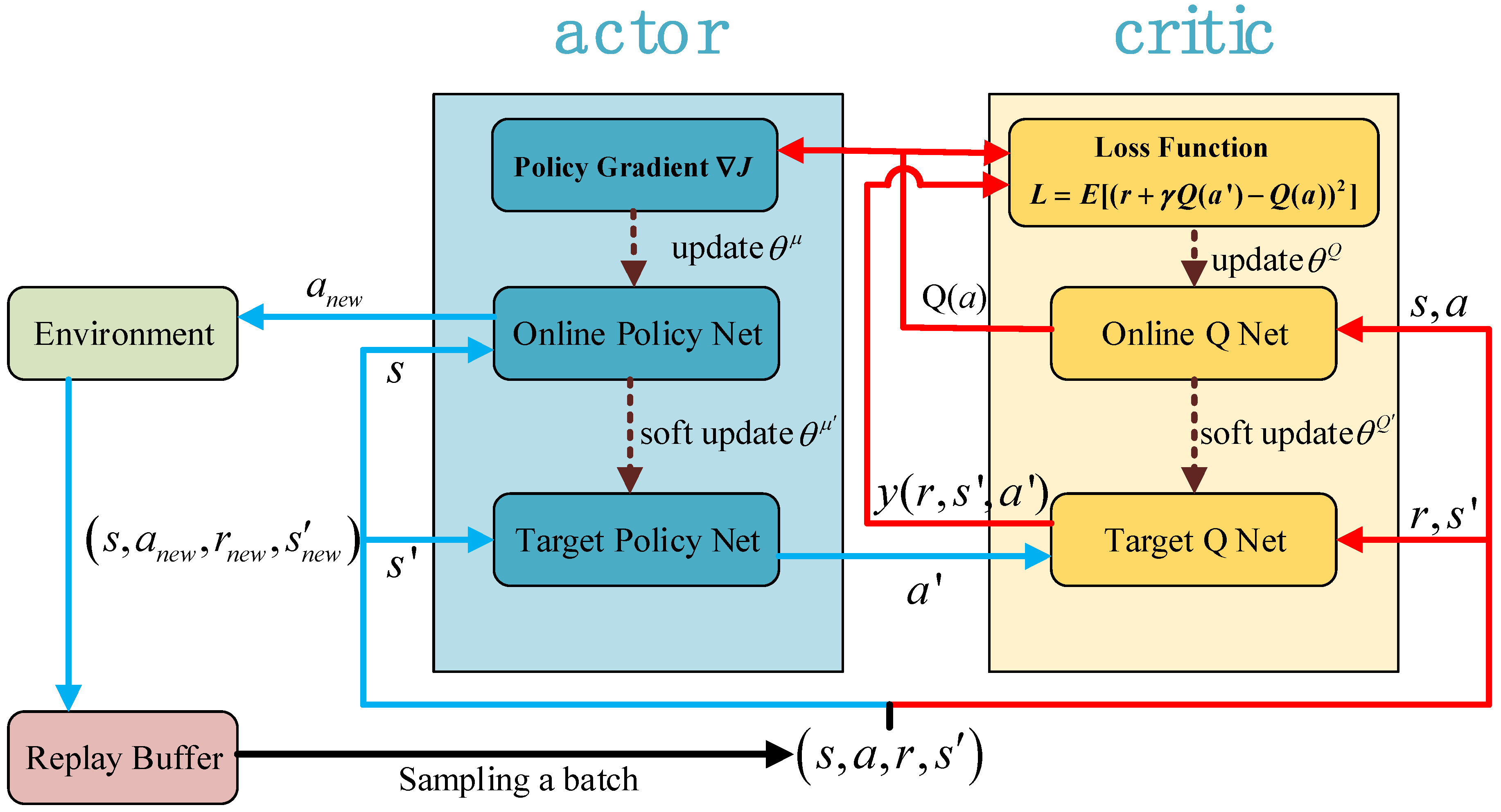
2.2. Deep Deterministic Policy Gradient Algorithm

As one of the most widely used deep reinforcement learning algorithms, the DDPG algorithm has been extensively adopted to solve the motion planning problem of manipulators in recent years due to its capability to deal with continuous action space.
The implementation framework of DDPG algorithm is demonstrated in Figure 2. As shown in Figure 2, the DDPG algorithm is constructed based on the actor-critic learning framework. The algorithm flow of actor-critic framework can be described as follows:
(1)
Firstly, a set of state s is obtained from the environment, and the actor generates a set of action a according to s;
(2)
After the action a is applied to the environment, a set of new state s′ and the reward r of the current step are fed back from the environment;
(3)
According to the reward r, the action evaluation function of critic is updated, and then the actor will update its policy function in the direction suggested by the critic. The above steps are one-step training of the actor-critic learning framework, and then continue the loop above until the training succeed.
Based on the actor-critic learning framework, the target network and replay buffer of deep Q network algorithm is introduced in DDPG to ensure the stability and convergence of the network. The network corresponding to the actor is called the policy network, which is divided into the online policy network and the target policy network. Similarly, the network corresponding to the critic is called the value network or Q network, which is divided into the online Q network and the target Q network, as shown in Figure 2. The main functions of the above networks are as follows:
(1)
Online policy network: The online policy network is mainly used to interact with the environment, generate action a according to the current state s, and update the parameter θμ in the policy network.
(2)
Target policy network: The target strategy network uses the data extracted from the replay buffer for training, and completes the task of selecting the next action a′ according to the next state s′. The network parameters θμ are copied and soft updated from the online policy network.
(3)
Online Q network: The task of the online Q network is to calculate the value Q ( s , a | θ Q ) of the current state s and action a, and update the parameter θQ in the Q network.
(4)
Target Q network: The target Q network is mainly used to calculate the “label” y = r + γ Q ( s , a | θ Q ) , and the network parameters θQ′ are copied and soft updated from the online Q network
The detailed algorithm flow will be shown in Section 3, which will not be repeated here.

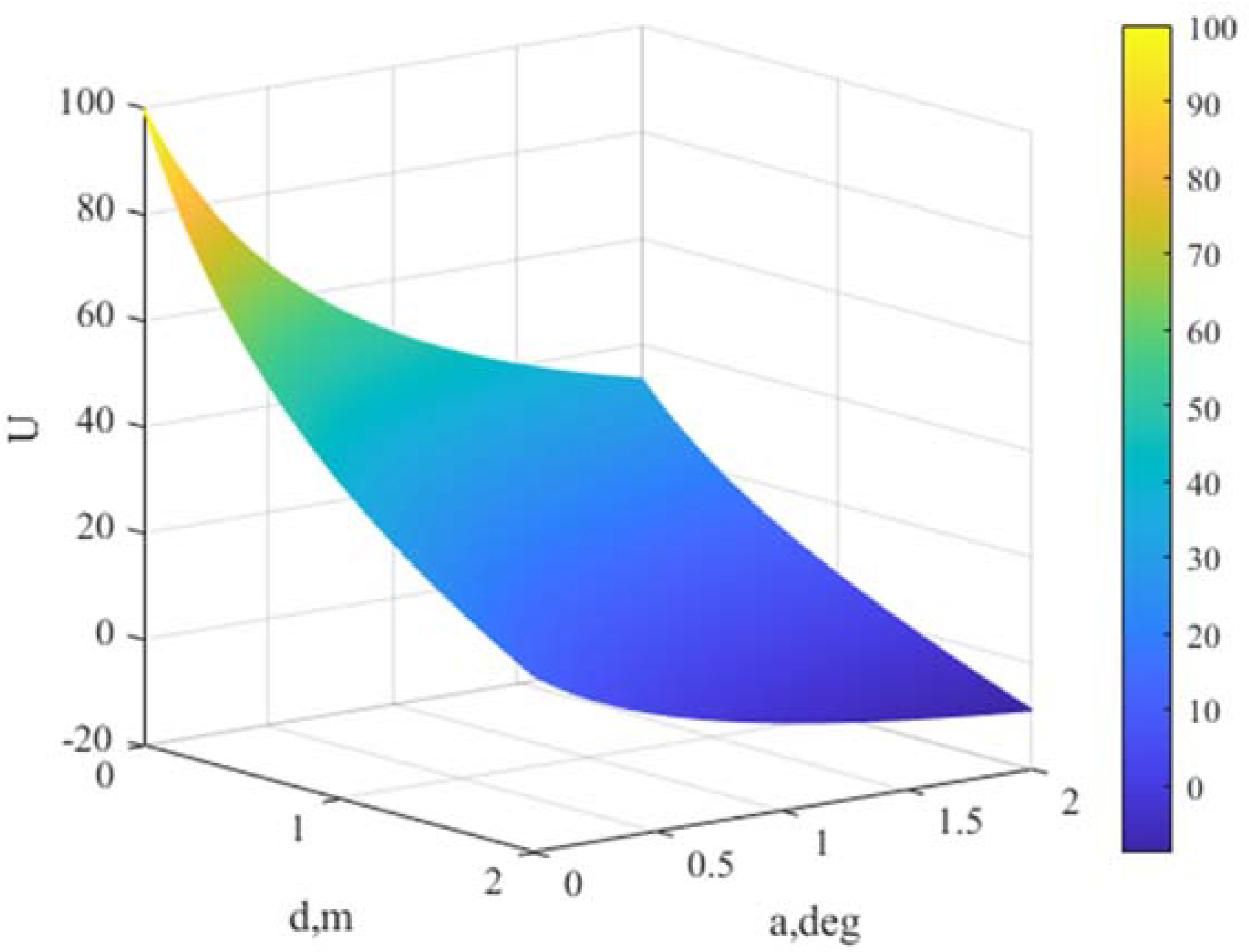
2.3. Artificial Potential Field

Artificial potential field is widely used to solve the path planning problem of robots, especially the path planning problem that needs to avoid obstacles. The principle of artificial potential field is to create a virtual gravitational field U a at the target that needs to be reached which can affect the entire environment, and create a virtual repulsion field U r with a certain range of influence at the obstacle. When the agent moves in the environment, the total potential field can be expressed as:
U t = U a + U r
The force experienced by the agent in the potential field is the negative gradient of potential energy:
F t = U a U r
Equation (14) means that the resultant force on the agent at any position of the environment is the sum of all gravitational and repulsive forces on that point. Under the action of resultant field force, the agent can bypass obstacles on its motion path and move towards the target along the negative gradient direction.

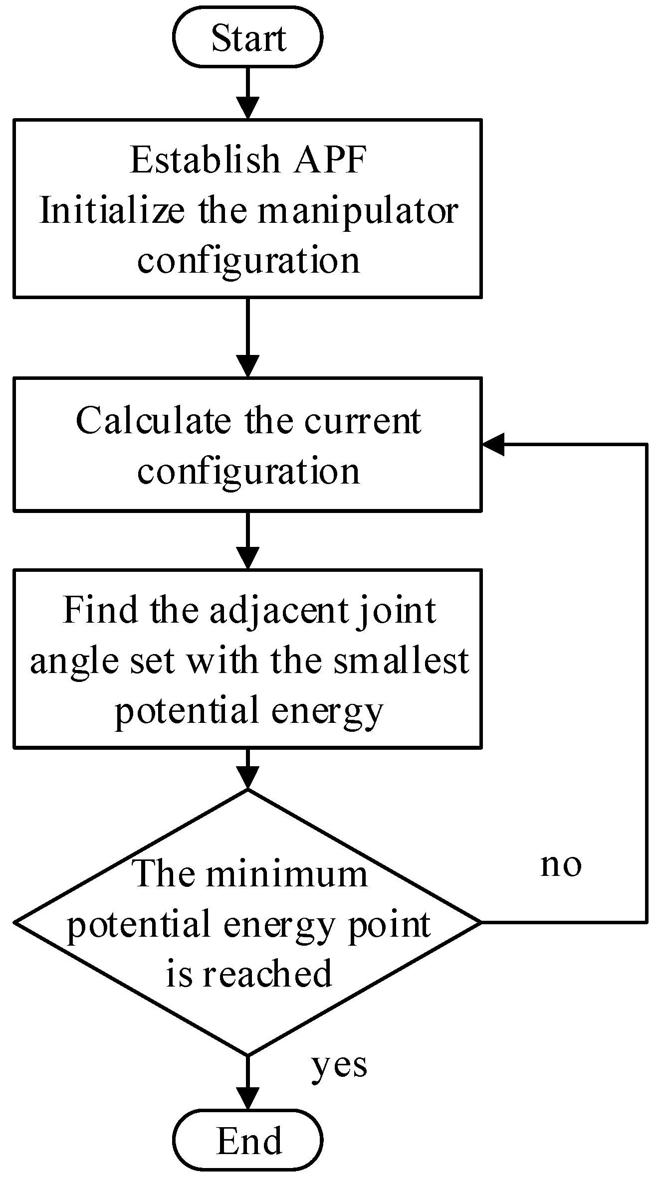
3. Motion Planning Algorithm Design

The algorithm flow of artificial potential field in manipulator path planning is shown in Figure 3, and it can be described as follows:
(1)
Establish artificial potential field according to the planning goal;
(2)
Calculate the configuration of the manipulator at the current step;
(3)
Traverse all the possible set of adjacent joint angles of the current configuration, find the set with the smallest total potential energy, and then proceed to (step 2).
Repeat the above cycle to obtain the complete optimal path along the negative gradient of potential field. However, this method requires substantial traversal and is easy to fall into a local minimum. Meanwhile, it has no generalization ability, which means that when the initial configuration or target point changes, the path needs to be replanned.
To overcome the above shortcomings of artificial potential field, considering that the deep reinforcement learning method can avoid local optima and has strong generalization ability, thus the DDPG algorithm is combined with the artificial potential field in this paper. The algorithm flowchart of the proposed motion planning method is demonstrated in Figure 3.
As shown in Figure 4, the brief steps of the proposed motion planning method are as follows:
(1)
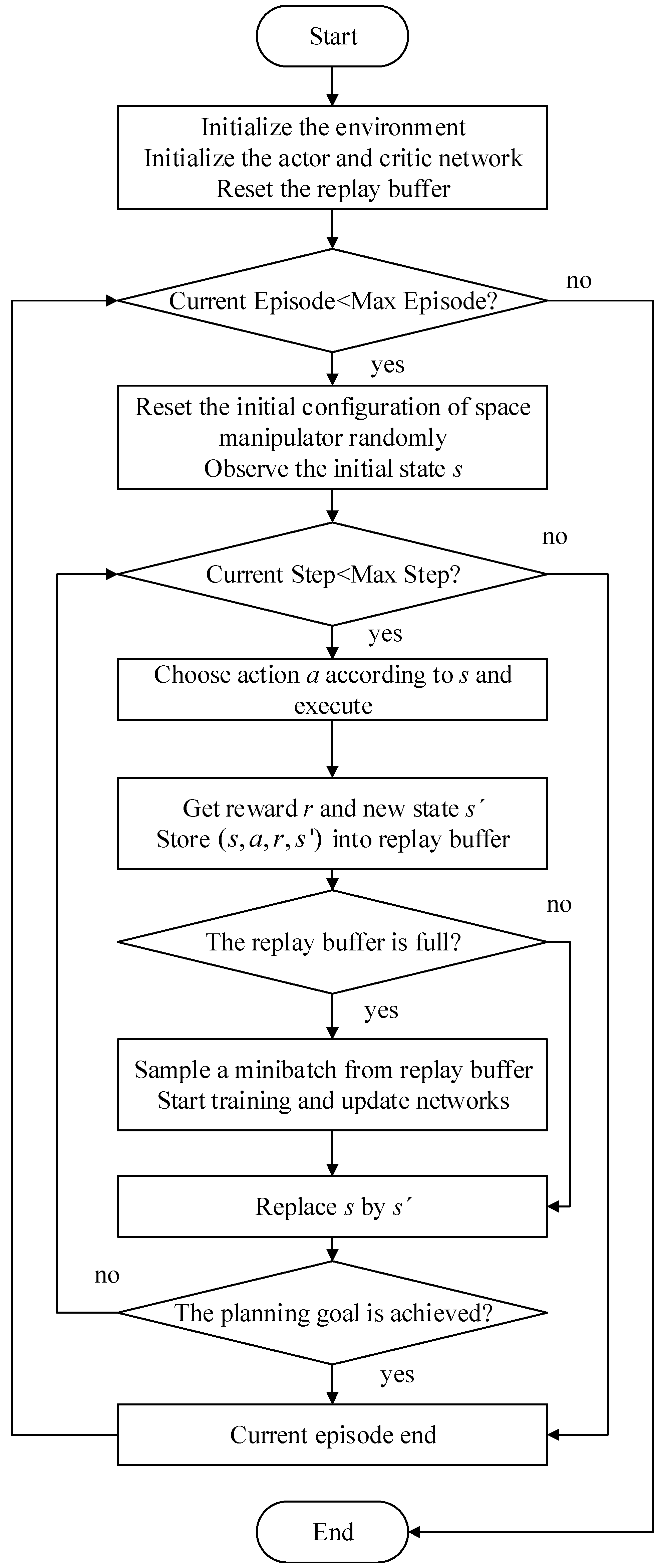
Establish the model of space manipulator and artificial potential field in the environment;
(2)
Observe current state s from environment and choose action a;
(3)
Execute action a, obtain the new state s′, and calculate reward r of current step based on the potential energy difference between state s and s′;
(4)
Store (s, a, r, s′) into the replay buffer, and start training when the replay buffer is full;
(5)
Replace s by s′ and go to step 2.
It should be noted that since the artificial potential field is introduced in the environment and potential energy difference is used for the reward calculation, the proposed method can well prevent the agent from learning the skill that can obtain higher rewards but fail to complete the goal, which is a frequent phenomenon in reinforcement learning [38].

3.1. Setting of the State and Action in DDPG

In the motion planning of space manipulator, the action can be chosen as the set of all the joint angular velocities as shown in Equation (15), since the kinematic model is adopted as a part of the environment.
a = [ ϕ ˙ 2 , ϕ ˙ 3 ϕ ˙ 8 ] T
The information contained in the state is crucial to the training of agent, hence in DDPG algorithm the state should be carefully set up to ensure that all the feature information is covered. Since the planning goal in this paper is to achieve the position and orientation alignment of the space manipulator end-effector simultaneously, the state must include not only the configuration information and velocity information of the space manipulator, but also the differences between the current and the target position and orientation of the end-effector. Meanwhile, the space manipulator is moving in the artificial potential field, thus the potential energy of the current configuration should also be included in the state. Based on the above analysis, the state can be set as follows:
s = [ r 0 T , θ 0 T , v 0 T , ω 0 T , ϕ T , a T , p e T , v e T , ω e T , p t T , d e t , a e t , U ] T
where θ 0 is the attitude of the base, p t denotes the target position and orientation of the end-effector, d e t represents the distance between the end-effector and the target point, and a e t denotes the angle between the point vector of the end-effector and the target vector. U denotes the potential energy corresponding to the current configuration of the space manipulator.

3.2. Reward Function Design

In the DDPG algorithm, the reward function determines the convergence and performance of the algorithm directly. Hence, it needs to be properly designed. Considering that the motion planning algorithm needs to achieve the main planning goal while complying with the self-collision avoidance constraint, the reward function is designed from these two aspects.

3.2.1. The Main Planning Goal

As mentioned before, the potential energy-based reward function can prevent the agent from learning the strategy that can obtain higher rewards but fail to complete the goal. Hence, an artificial potential field is designed to describe the reward of each step in DDPG. Since the main planning goal is to achieve the position and orientation alignment of the space manipulator end-effector simultaneously, d e t and a e t are the main basis of potential field design. The form of the designed potential field is as follows:
U ( d e t , a e t ) = K d d e t + K a ( d e t + 1 ) ( a e t + 1 )
where K d and K a are the weight coefficients, and in this paper a set of coefficients is chosen as K d = 10 , K a = 100 . The potential field has the following characteristics: When d e t is large, the potential energy is mainly determined by d e t , and the influence of a e t gradually increase with d e t decrease. When both d e t and a e t tend to zero, the potential energy reaches a maximum. The visualization of potential field is demonstrated in Figure 5.
Let the corresponding potential energy of the current state s and the next state s be U t ( d e t , a e t ) and U t + 1 ( d e t , a e t ) , respectively. Then, the reward function can be expressed as follows:
r = U t + 1 ( d e t , a e t ) U t ( d e t , a e t )
The reward function in Equation (18) means that when the space manipulator transitions from a state with low potential energy to a state with high potential energy, a positive reward will be obtained, otherwise the reward will be negative. Additionally, the total reward of each episode can be calculated as:
R = t = 0 f 1 ( U t + 1 ( d e t , a e t ) U t ( d e t , a e t ) ) = U f ( d e t , a e t ) U 0 ( d e t , a e t )
where R denotes the total reward for this episode, and f is the total step of this episode. U f ( d e t , a e t ) and U 0 ( d e t , a e t ) represent the corresponding potential energy of the final state and the initial state, respectively.

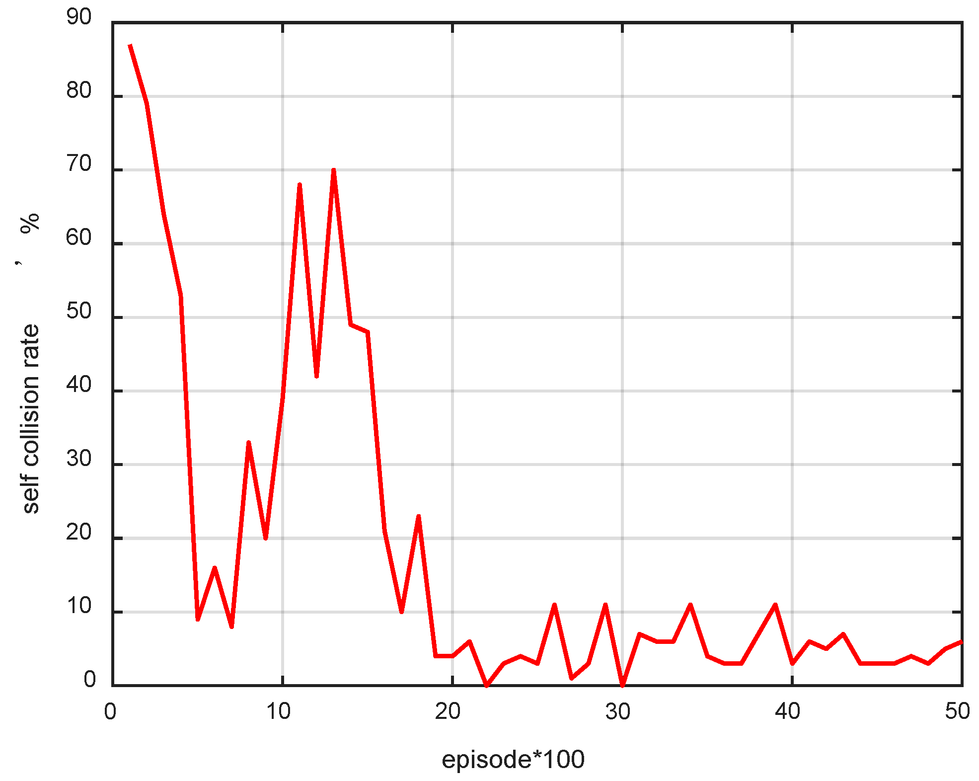
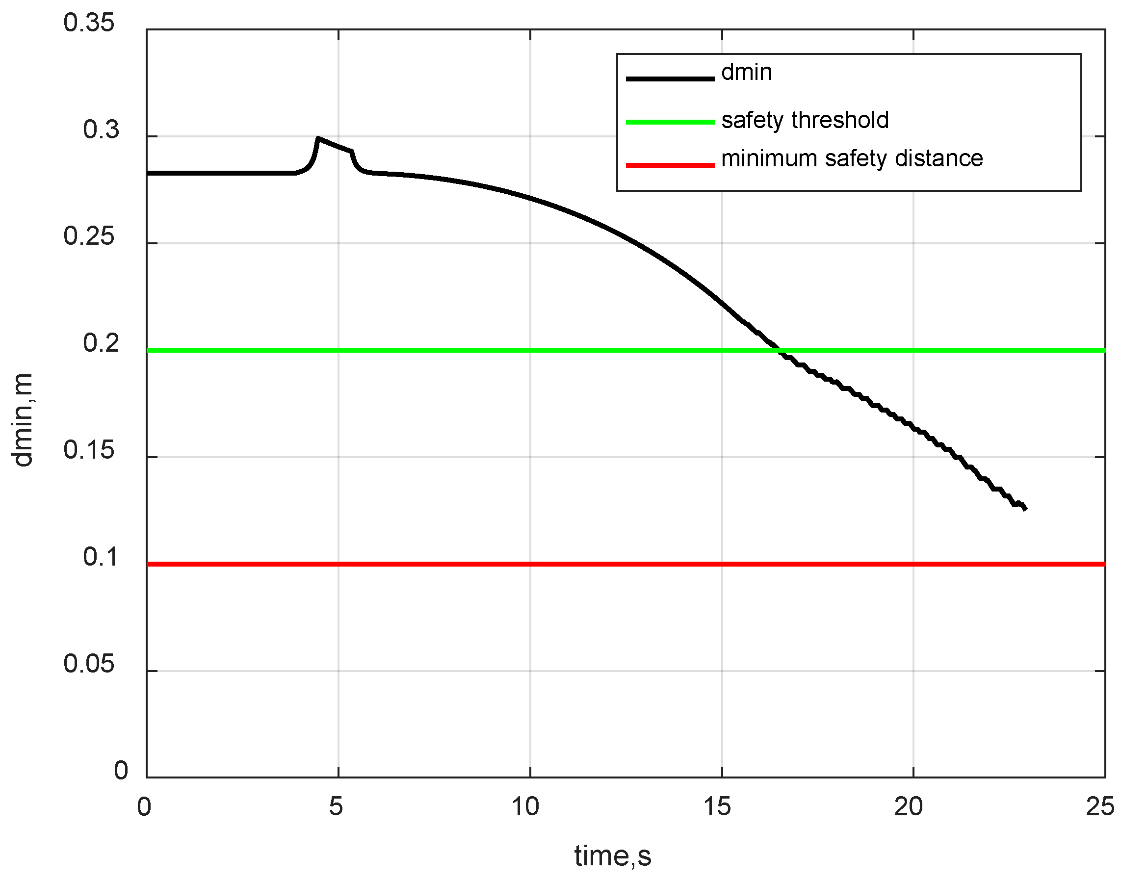
3.2.2. Self-Collision Avoidance Constraint

During the operation of space manipulator, collisions between each link of space manipulator must be avoided for operational security, hence the self-collision avoidance constraint is also considered in reward function design. Considering that the collision detection is required in each step of DDPG algorithm, a complicated collision detective model will inevitably bring heavy calculation burden, and may even cause the failure of the planning algorithm. A vector-based calculation method of the minimum distance between each link proposed in reference [36] is introduced in this paper.
According to the configuration of the 7-DOF space manipulator, the collision situation of each link is listed in Table 2, where the check mark means collision may occurred between the links on the corresponding row and column, while the cross indicates that the collision will not occur.
According to Table 2, the minimum distance between each link of the space manipulator can be described as follows:
d min = min { d 14 , d 15 , d 16 , d 17 , d 18 , d 28 , d 38 , d 48 , d 58 }
where d i j ( i [ 1 , 5 ] , j [ 4 , 8 ] ) denotes the minimum distance between link i and link j, which can be calculated by the method proposed in reference [36].
To achieve the self-collision avoidance, a penalty term related to d min is added to the reward function in Equation (18). The penalty term r d is designed as follows:
{ r d = 0.1 , d min 0.1 m r d = 1 k 1 d min 2 + k 2 , 0.1 m < d min 0.2 m r d = 0 , d min > 0.2 m
where the coefficients k 1 and k 2 are chosen as k 1 = 2000 , k 2 = 20 . From Equation (21) it can be seen that the penalty term has the following properties: When d min is large enough, the current configuration of the space manipulator is considered safe, and the penalty is set to 0; when d min exceeds the safety threshold, as d min decreases, the absolute value of penalty will rapidly increase; when d min is less than the minimum safety distance, a very large penalty will be provided to the reward function.
Thus, the composite reward function can be expresses as:
r c = r + r d

4. Simulation and Analysis

4.1. Simulation Setup
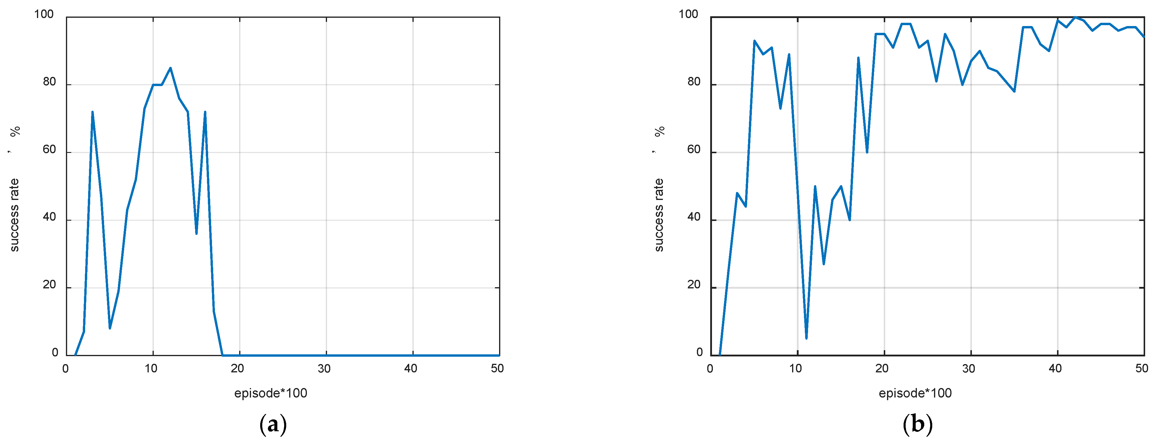
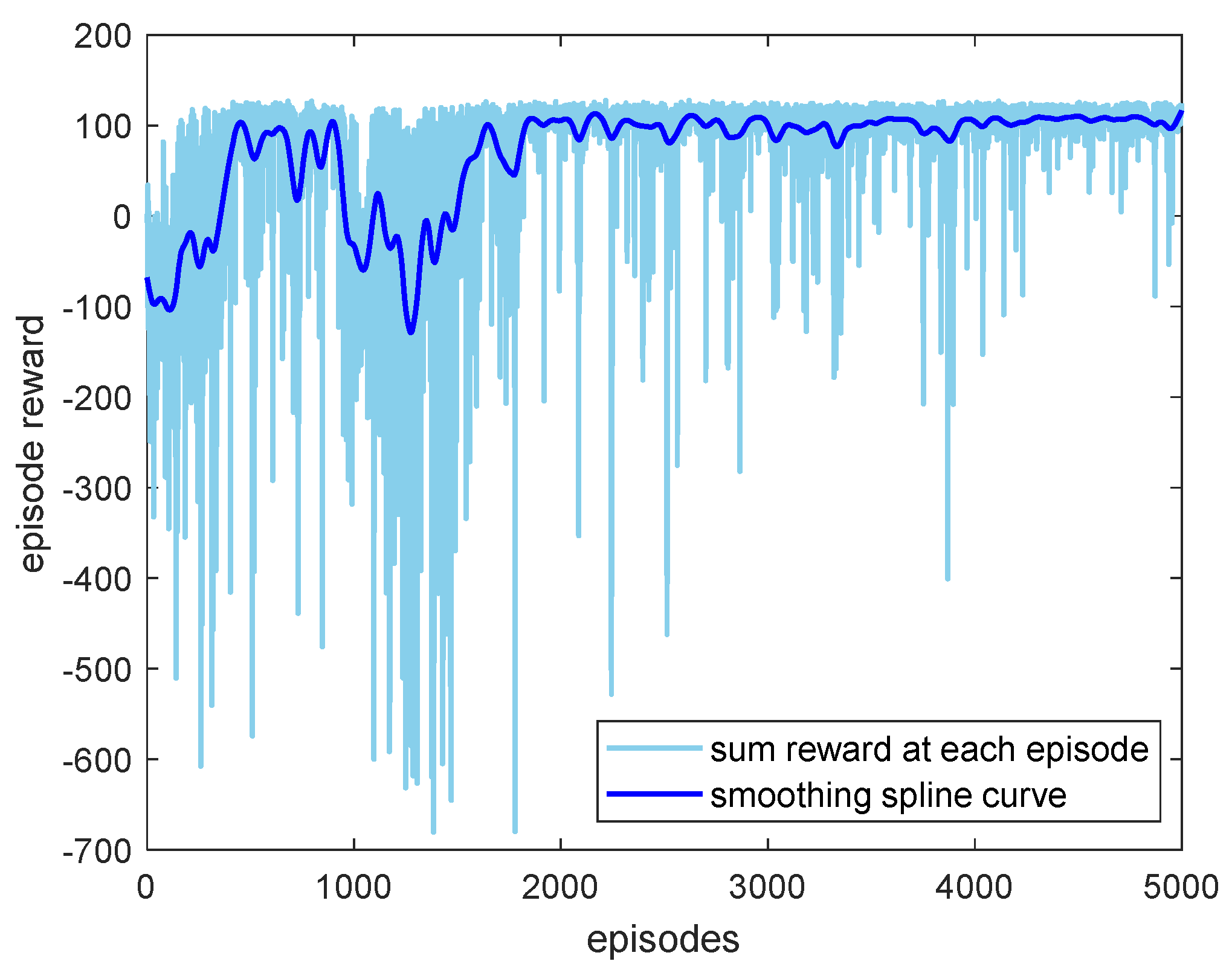
The simulation is implemented in Python 3.6 (https://www.python.org/). The parameter settings of actor and critic network in DDPG are as follows: The number of hidden layers is set to 2, each layer has 200 neurons, and the learning rate of both networks is set to 0.001. The size of the replay buffer is set to 80,000, and the size of the mini batch sampled at each step is 32. The maximum number of steps in each episode is 8000, and the step length is 0.03 s, which means that the maximum time length of each episode is 240 s. Additionally, the maximum number of episodes is set to 5000. The reference configuration of the space manipulator is shown in Figure 1, and the initial configuration for training and testing are listed in Table 3. It should be noted that since joint 1 is a fixed joint and joint 8 has no contribution to the position and orientation of the end-effector, so only joints 2–7 are set. The target point represent in inertial coordinate is (0.5, 1.6, 1), and the target orientation vector is (0, 1, 0).

4.2. DDPG Training

The training of the designed algorithm for the position and orientation alignment of the space manipulator end-effector is carried out. The planning goal is considered to be achieved when d e t is within 0.05 m and a e t is less than 1°. To show the superiority of the motion planning approach based on deep reinforcement learning and artificial potential field, a comparison is carried out by using the potential function shown in Equation (17) as the reward function instead of the potential difference shown in Equation (18) according to the reward function design method proposed in Ref. [36], and the simulation results are demonstrated in Figure 6, Figure 7 and Figure 8.
Figure 6 demonstrates the success rate of the proposed motion planning approach and the DDPG-based motion planning method proposed in reference [36]. It can be seen that the success rate of the proposed motion planning approach can be maintained above 90% after about 4000 episodes, while the success rate of the DDPG-base method shows a trend of rising first and then falling, and ultimately cannot converge to a desired result. This is because in the DDPG-based method, when the end-effector is always hovering near the target point, the agent can obtain a greater total reward than completing the orientation alignment, which proved that the introduction of artificial potential field can prevent the agent from learning the strategy that can obtain higher rewards but fail to complete the goal.
Figure 7 gives out the episode reward, the light-blue line represents the sum reward at each episode, while the dark-blue line is the smoothing spline curve of the episode reward. According to the dark-blue line, the episode reward has the same trend as the success rate, which further proves that the designed algorithm has good convergence.
The self-collision rate is shown in Figure 8. As can be seen, the self-collision rate shows an opposite trend to the success rate, that is, there is a high probability that the planning goal cannot be successfully achieved when self-collisions occur. The self-collision rate finally converges to about 5%, which verifies the collision-avoidance capability of the proposed method.

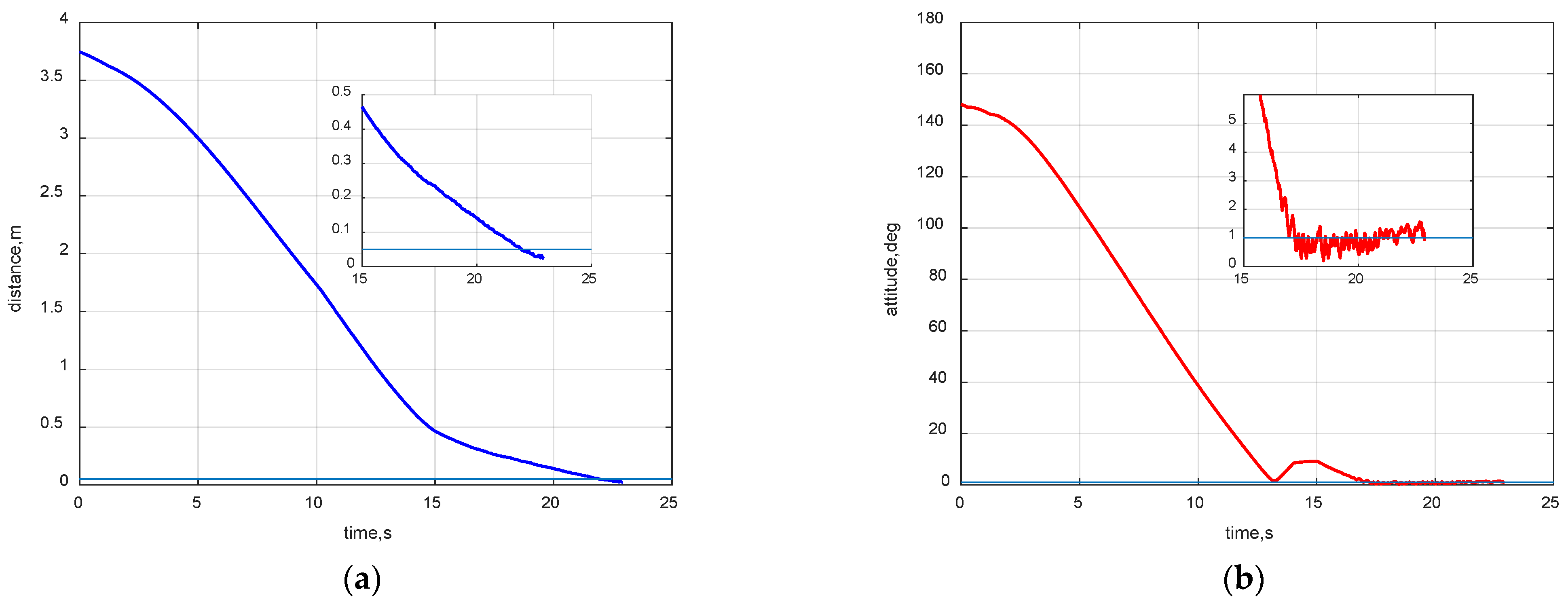
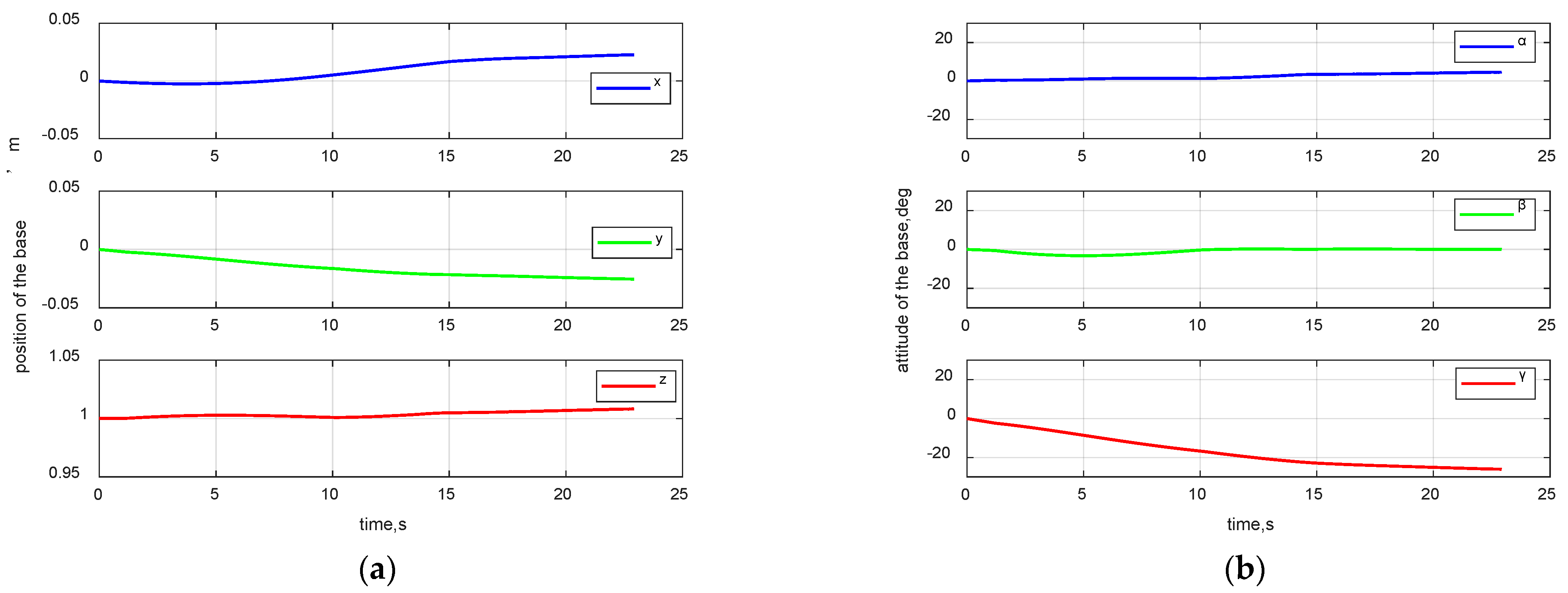
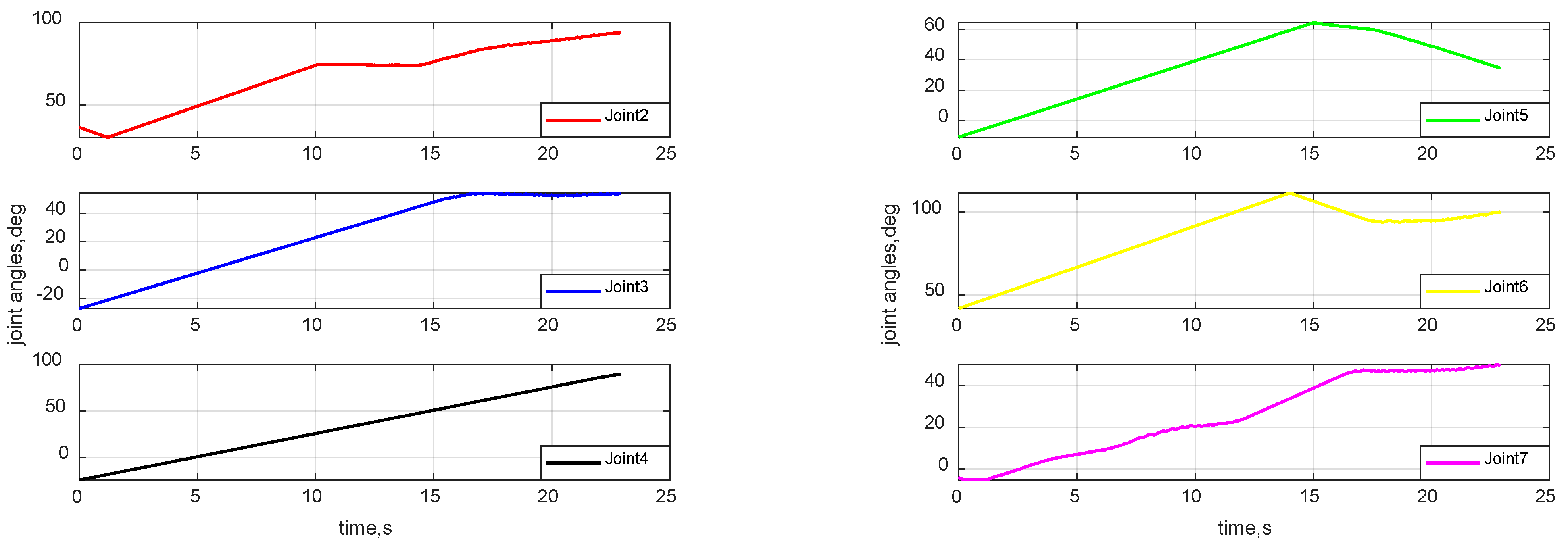
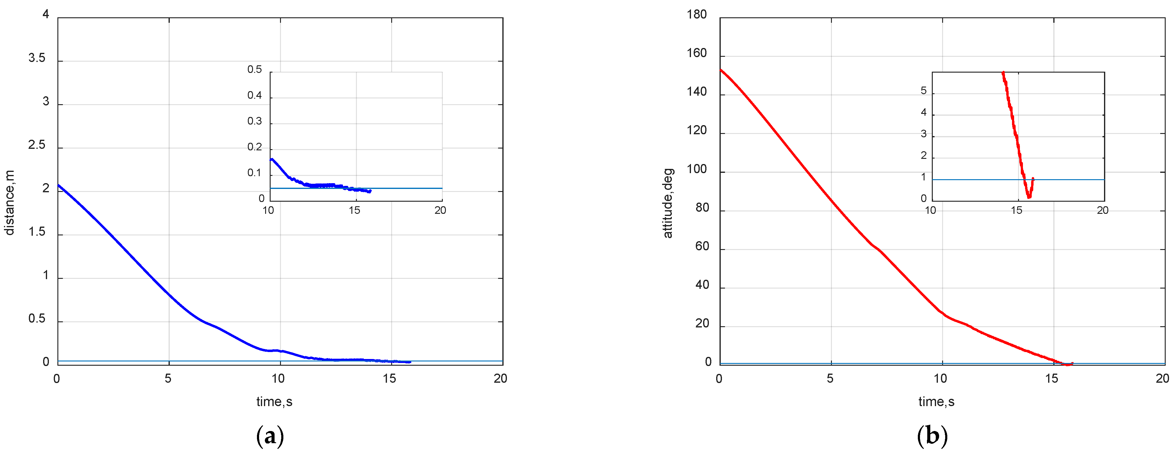
4.3. Space Mission Application Case

Based on the trained DDPG networks, two space mission scenarios are simulated to test the effectiveness of the proposed approach and demonstrate it is not sensitive to the initial configuration of the space manipulator. The initial configuration of the space manipulator is set as shown in Table 3 with the initial joint angles 0.635, −0.474, −0.423, −0.190, 0.727, and −0.072 rad. The simulation results are shown in Figure 9, Figure 10, Figure 11 and Figure 12.
The differences in the distance and angle between the end-effector and the target position and orientation are shown in Figure 9. From Figure 9 it is obvious that after about 23 s, the position and orientation deviation have converged to the preset accuracy range simultaneously, which verified the effectiveness of the proposed motion planning approach.
The minimum distance between all links during the motion of space manipulator is given in Figure 10. It can be seen that the minimum distance between all links gradually decreases and enters the safety threshold around 16 s, but it is always greater than the minimum safety distance of 0.1 m during the motion, which verified the effectiveness of the self-collision avoidance constraint. To show the motion characteristics of the space manipulator more clearly, the trajectory of the base and all joint angles are demonstrated in Figure 11 and Figure 12.
Another set of simulations with different initial joint angles is conducted to demonstrate the proposed method is not sensitive to the initial configuration of the space manipulator. The initial configuration settings are shown in Table 3, and the initial joint angles are set to (−1.6, −12.0, −33.9, 6.4, 17.6, 39.5) rad. The results are shown in Figure 13.
From Figure 13, it can be seen that when the distance between the initial position of the space manipulator end-effector and the target point becomes shorter, the proposed motion planning approach can still generate a trajectory that can achieve the position and orientation alignment of the end-effector, which indicated that the proposed approach is not sensitive to the initial configuration of the space manipulator.

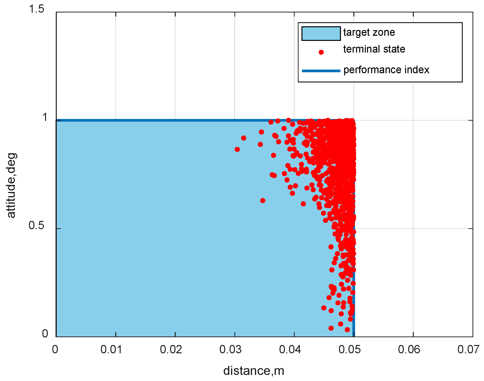
4.4. Robustness Verification

In practical applications, the state information of the space manipulator, such as base position, base attitude, and joint angles obtained by the measuring units, usually has errors and uncertainties, so the robustness of the motion planning is required. To verify the robustness of the proposed approach, the Monte Carlo simulation is carried out for the mission scenario, where the state information input to the planning algorithm deviates from the actual state. The initial configuration of the space manipulator is shown in Table 3, and the initial joint angles are set to (0.1π, 0.1π, 0.2π, 0.5π, 0.5π, 0.3π) rad. During motion, random measuring errors in the range of [−5, +5] deg are added to all joint angle inputs in each step, 1000 Monte Carlo simulations are performed, and the result is shown in Figure 14.
As presented in Figure 14, the end-effector terminal states in all 1000 Monte Carlo simulations are within the target zone, verifying that the proposed method has strong robustness to measuring errors. Note that all terminal state points should be on the blue line in theory if the planning goal is achieved; however, since the sampling is discrete during the simulation process, there will be cases where the terminal state point is in the target zone.

5. Conclusions

A motion planning approach based on DDPG algorithm and artificial potential field is proposed in this paper to achieve the position and orientation alignment of the space manipulator end-effector during on-orbit operation. The kinematic characteristics of the free-floating 7-DOF space manipulator is described by the generalized Jacobian matrix, and the framework of the motion planning algorithm is established based on DDPG algorithm. The artificial potential field is established in the environment part of the DDPG algorithm, and the reward function is designed on this basis, which improved the convergence of the DDPG algorithm. Considering the operational security of the space manipulator, the self-collision avoidance constraint is taken into account. The effectiveness and superiority of proposed approach are verified by comparison simulations. The results in this paper can provide theoretical support for on-orbit operation tasks of space manipulator with end-effector position and orientation alignment requirements.

Author Contributions

Conceptualization, Y.L., D.L., W.Z., J.S., X.Z. and S.L.; methodology, Y.L., D.L., W.Z. and S.L.; software, Y.L. and D.L.; validation, Y.L., D.L. and S.L.; formal analysis, Y.L. and D.L.; investigation, Y.L., D.L. and S.L.; resources, S.L.; data curation, Y.L. and D.L.; writing—original draft preparation, Y.L., D.L. and S.L.; writing—review and editing, Y.L., D.L., W.Z., J.S., X.Z. and S.L.; visualization, Y.L. and D.L.; supervision, S.L.; project administration, S.L.; funding acquisition, S.L. All authors have read and agreed to the published version of the manuscript.

Funding

This work was supported by the National Natural Science Foundation of China (No. 11972182), and Funded Project of Shanghai Aerospace Science and Technology (No. SAST2020-063). The authors fully appreciate their financial supports.

Institutional Review Board Statement

Not applicable.

Informed Consent Statement

Not applicable.

Data Availability Statement

Not applicable.

Acknowledgments

The authors would like to thank the reviewers for their constructive comments and suggestions that may help improve this paper.

Conflicts of Interest

The authors declare that they have no known competing financial interests or personal relationships that could have appeared to influence the work reported in this paper.

References

  1. Liu, F.; Jin, D. A high-efficient finite difference method for flexible manipulator with boundary feedback control. Space Sci. Technol. 2021, 2021, 9874563. [Google Scholar] [CrossRef]
  2. Wu, Z.; Chen, Y.; Xu, W. A light space manipulator with high load-to-weight ratio: System development and compliance control. Space Sci. Technol. 2021, 2021, 9760520. [Google Scholar] [CrossRef]
  3. Li, S.; She, Y.; Sun, J. Inertial parameter estimation and control of non-cooperative target with unilateral contact constraint. Chin. J. Aeronaut. 2021, 34, 225–240. [Google Scholar] [CrossRef]
  4. Li, S.; She, Y. Recent advances in contact dynamics and post-capture control for combined spacecraft. Prog. Aerosp. Sci. 2021, 120, 100678. [Google Scholar] [CrossRef]
  5. Li, J.; Wang, Y.; Liu, Z.; Jing, X.; Hu, C. A new recursive composite adaptive controller for robot manipulators. Space Sci. Technol. 2021, 2021, 9801421. [Google Scholar] [CrossRef]
  6. Sun, Z.; Yang, H.; Dong, Q.; Mo, Y.; Li, H.; Jiang, Z. Autonomous Assembly Method of 3-Arm Robot to Fix the Multipin and Hole Load Plate on a Space Station. Space Sci. Technol. 2021, 2021, 9815389. [Google Scholar] [CrossRef]
  7. Jiang, Z.; Cao, X.; Huang, X.; Li, H.; Ceccarelli, M. Progress and Development Trend of Space Intelligent Robot Technology. Space Sci. Technol. 2022, 2022, 9832053. [Google Scholar] [CrossRef]
  8. Wang, R.; Liang, C.; Pan, D.; Zhang, X.; Xin, P.; Du, X. Research on a Visual Servo Method of a Manipulator Based on Velocity Feedforward. Space Sci. Technol. 2021, 2021, 9763179. [Google Scholar] [CrossRef]
  9. Wang, M.; Luo, J.; Fang, J.; Yuan, J. Optimal trajectory planning of free-floating space manipulator using differential evolution algorithm. Adv. Space Res. 2018, 61, 1525–1536. [Google Scholar] [CrossRef]
  10. Liu, X.; Baoyin, H.; Ma, X. Optimal path planning of redundant free-floating revolute-jointed space manipulators with seven links. Multibody Syst. Dyn. 2013, 29, 41–56. [Google Scholar] [CrossRef]
  11. Rybus, T.; Wojtunik, M.; Basmadji, F.L. Optimal collision-free path planning of a free-floating space robot using spline-based trajectories. Acta Astronaut. 2022, 190, 395–408. [Google Scholar] [CrossRef]
  12. Jin, R.; Rocco, P.; Geng, Y. Cartesian trajectory planning of space robots using a multi-objective optimization. Aerosp. Sci. Technol. 2021, 108, 106360. [Google Scholar] [CrossRef]
  13. Zhang, Q.; Kang, G.; Wu, J.; Zhang, H. Pre-impact Trajectory Planning of Nonredundant Free-Floating Space Manipulator. In Proceedings of the 2020 5th International Conference on Automation, Control and Robotics Engineering (CACRE), Dalian, China, 19–20 September 2020; pp. 58–65. [Google Scholar]
  14. Lu, X.; Jia, Y. Trajectory planning of free-floating space manipulators with spacecraft attitude stabilization and manipulability optimization. IEEE Trans. Syst. Man Cybern. Syst. 2020, 51, 7346–7362. [Google Scholar] [CrossRef]
  15. Misra, G.; Bai, X. Optimal path planning for free-flying space manipulators via sequential convex programming. J. Guid. Control. Dyn. 2017, 40, 3019–3026. [Google Scholar] [CrossRef]
  16. Misra, G.; Bai, X. Task-Constrained Trajectory Planning of Free-Floating Space-Robotic Systems Using Convex Optimization. J. Guid. Control. Dyn. 2017, 40, 2857–2870. [Google Scholar] [CrossRef]
  17. Lu, J.; Yang, H. Trajectory Planning of Satellite Base Attitude Disturbance Optimization for Space Robot. In Proceedings of the 2020 3rd International Conference on Control and Robots (ICCR), Tokyo, Japan, 26–29 December 2020; pp. 85–89. [Google Scholar]
  18. Khatib, O. Real-time obstacle avoidance for manipulators and mobile robots. In Autonomous Robot Vehicles; Springer: Berlin/Heidelberg, Germany, 1986. [Google Scholar]
  19. Liu, S.; Zhang, Q.; Zhou, D. Obstacle avoidance path planning of space manipulator based on improved artificial potential field method. J. Inst. Eng. Ser. C 2014, 95, 31–39. [Google Scholar] [CrossRef]
  20. Wang, W.; Zhu, M.; Wang, X.; He, S.; He, J.; Xu, Z. An improved artificial potential field method of trajectory planning and obstacle avoidance for redundant manipulators. Int. J. Adv. Robot. Syst. 2018, 15, 1729881418799562. [Google Scholar] [CrossRef] [Green Version]
  21. Li, H.; Wang, Z.; Ou, Y. Obstacle avoidance of manipulators based on improved artificial potential field method. In Proceedings of the 2019 IEEE International Conference on Robotics and Biomimetics (ROBIO), Dali, China, 6–8 December 2019; pp. 564–569. [Google Scholar]
  22. Zhang, N.; Zhang, Y.; Ma, C.; Wang, B. Path planning of six-DOF serial robots based on improved artificial potential field method. In Proceedings of the 2017 IEEE International Conference on Robotics and Biomimetics (ROBIO), Macau, China, 5–8 December 2017; pp. 617–621. [Google Scholar]
  23. Huang, X.; Li, S.; Yang, B.; Sun, P.; Liu, X.; Liu, X. Spacecraft guidance and control based on artificial intelligence: Review. Acta Aeronaut. Astronaut. Sin. 2021, 42, 524201. [Google Scholar]
  24. She, Y.; Li, S.; Xin, M. Quantum-interference Artificial Neural Network with Application to Space Manipulator Control. IEEE Trans. Aerosp. Electron. Syst. 2021, 57, 2167–2182. [Google Scholar] [CrossRef]
  25. Nguyen, H.; La, H. Review of deep reinforcement learning for robot manipulation. In Proceedings of the 2019 Third IEEE International Conference on Robotic Computing (IRC), Naples, Italy, 25–27 February 2019; pp. 590–595. [Google Scholar]
  26. Yan, C.; Zhang, Q.; Liu, Z.; Wang, X.; Liang, B. Control of free-floating space robots to capture targets using soft q-learning. In Proceedings of the 2018 IEEE International Conference on Robotics and Biomimetics (ROBIO), Kuala Lumpur, Malaysia, 12–15 December 2018; pp. 654–660. [Google Scholar]
  27. Liang, B.; Chen, Z.; Guo, M.; Wang, Y.; Wang, Y. Space robot target intelligent capture system based on deep reinforcement learning model. J. Phys. Conf. Ser. 2021, 1848, 012078. [Google Scholar] [CrossRef]
  28. Stan, L.; Nicolescu, A.F.; Pupăză, C. Reinforcement learning for assembly robots: A review. Proc. Manuf. Syst. 2020, 15, 135–146. [Google Scholar]
  29. Li, Z.; Ma, H.; Ding, Y.; Wang, C.; Jin, Y. Motion planning of six-dof arm robot based on improved DDPG algorithm. In Proceedings of the 2020 39th Chinese Control Conference (CCC), Shenyang, China, 27–29 July 2020; pp. 3954–3959. [Google Scholar]
  30. Zhou, J.; Zheng, H.; Zhao, D.; Chen, Y. Intelligent Control of Manipulator Based on Deep Reinforcement Learning. In Proceedings of the 2021 12th International Conference on Mechanical and Aerospace Engineering (ICMAE), Athens, Greece, 16–19 July 2021; pp. 275–279. [Google Scholar]
  31. Man, H.; Ge, N.; Xu, L. Intelligent Motion Control Method Based on Directional Drive for 3-DOF Robotic Arm. In Proceedings of the 2021 5th International Conference on Robotics and Automation Sciences (ICRAS), Wuhan, China, 11–13 June 2021; pp. 144–149. [Google Scholar]
  32. Zeng, R.; Liu, M.; Zhang, J.; Li, X.; Zhou, Q.; Jiang, Y. Manipulator control method based on deep reinforcement learning. In Proceedings of the 2020 Chinese Control and Decision Conference (CCDC), Hefei, China, 22–24 August 2020; pp. 415–420. [Google Scholar]
  33. Du, D.; Zhou, Q.; Qi, N.; Wang, X.; Liu, Y. Learning to Control a Free-floating Space Robot using Deep Reinforcement Learning. In Proceedings of the 2019 IEEE International Conference on Unmanned Systems (ICUS), Beijing, China, 17–19 October 2019; pp. 519–523. [Google Scholar]
  34. Hu, X.; Huang, X.; Hu, T.; Shi, Z.; Hui, J. MRDDPG Algorithms for Path Planning of Free-Floating Space Robot. In Proceedings of the 2018 IEEE 9th International Conference on Software Engineering and Service Science (ICSESS), Beijing, China, 23–25 November 2018; pp. 1079–1082. [Google Scholar]
  35. Wu, Y.H.; Yu, Z.C.; Li, C.Y.; He, M.J.; Hua, B.; Chen, Z.M. Reinforcement learning in dual-arm trajectory planning for a free-floating space robot. Aerosp. Sci. Technol. 2020, 98, 105657. [Google Scholar] [CrossRef]
  36. Li, Y.; Hao, X.; She, Y.; Li, S.; Yu, M. Constrained motion planning of free-float dual-arm space manipulator via deep reinforcement learning. Aerosp. Sci. Technol. 2021, 109, 106446. [Google Scholar] [CrossRef]
  37. Umetani, Y.; Yoshida, K. Resolved motion rate control of space manipulators with generalized Jacobian matrix. IEEE Trans. Robot. Autom. 1989, 5, 303–314. [Google Scholar] [CrossRef]
  38. Sutton, R.S.; Barto, A.G. Reinforcement Learning: An Introduction; MIT Press: Cambridge, MA, USA, 2018. [Google Scholar]
Figure 1. The configuration and kinematic relationship of the 7-DOF space manipulator.
Aerospace 09 00163 g001
Figure 2. The implementation framework of DDPG algorithm.
Aerospace 09 00163 g002
Figure 3. The algorithm flowchart of APF in manipulator motion planning.
Aerospace 09 00163 g003
Figure 4. The algorithm flowchart of the proposed motion planning method.
Aerospace 09 00163 g004
Figure 5. Visualization of the potential field.
Aerospace 09 00163 g005
Figure 6. Success rate per 100 episodes. (a) The motion planning method in reference [36]; (b) The motion planning method proposed in this paper.
Aerospace 09 00163 g006
Figure 7. The episode reward.
Aerospace 09 00163 g007
Figure 8. The self-collision rate per 100 episodes (“*” stands for multiplication).
Aerospace 09 00163 g008
Figure 9. Time history of the distance and angle differences. (a) The distance between the end-effector position and the target point; (b) The angle between the end-effector orientation and the target orientation.
Aerospace 09 00163 g009
Figure 10. The minimum distance between all links.
Aerospace 09 00163 g010
Figure 11. Time history of the position and attitude of the base. (a) The position of the base; (b) The attitude of the base.
Aerospace 09 00163 g011
Figure 12. Time history of all joint angles.
Aerospace 09 00163 g012
Figure 13. Time history of the distance and angle differences. (a) The distance between the end-effector position and the target point; (b) The angle between the end-effector orientation and the target orientation.
Aerospace 09 00163 g013
Figure 14. The end-effector distance–attitude dispersion of Monte Carlo simulation.
Aerospace 09 00163 g014
Table 1. Dynamic parameters of the 7-DOF space manipulator.
BodyMass, kgShape I x ,   kg / m 2 I y ,   kg / m 2 I z ,   kg / m 2 Length, m
Base3000Box835835835[1, 1, 1]
Link 1 5Cylinder0.040.040.006250.3
Link 2 5Cylinder0.020.020.006250.2
Link 3 5Cylinder0.020.020.006250.2
Link 4 20Cylinder1.681.680.0251
Link 5 20Cylinder1.681.680.0251
Link 6 5Cylinder0.020.020.006250.2
Link 7 5Cylinder0.020.020.006250.2
Link 8 5Cylinder0.040.040.006250.3
Table 2. The collision situation of each link.
Link 1Link 2Link 3Link 4Link 5Link 6Link 7Link 8
Link 1--×
Link 2---××××
Link 3×---×××
Link 4×---××
Link 5××---×
Link 6×××---×
Link 7××××---
Link 8×--
Table 3. The initial configuration of the space manipulator.
StatesInitial Configuration for TrainingInitial Configuration for Testing
r 0 (0, 0, 1)(0, 0, 1)
θ 0 (0, 0, 0)(0, 0, 0)
v 0 (0, 0, 0)(0, 0, 0)
ω 0 (0, 0, 0)(0, 0, 0)
ϕ Random selected within
movable range of joints
(0.635, −0.474, −0.423, −0.190, 0.727, −0.072)
(0.648, 0.232, 0.546, 0.321, −0.389, −0.382)
ϕ ˙ 00
Publisher’s Note: MDPI stays neutral with regard to jurisdictional claims in published maps and institutional affiliations.

