1. Introduction
In the last decade, cooperative guidance has received significant attention for its effectiveness in increasing the rate of defense penetration and aircraft-target interception. Well-coordinated multiple vehicles tend to be more efficient. They can raise the effectiveness of defense penetration by attacking the target from numerous different directions simultaneously. Cooperative guidance against maneuvering targets allows for a multi-vehicle-to-target interception posture. As a result, the target’s cost of maneuvering to escape increases, and the interception success rate improves.
The cooperative guidance law can be functionally divided into impact angle cooperation and impact time cooperation. The information exchanged between the vehicles was not considered in the initial study. Instead, the cooperative attack was achieved through predefined impact angles and impact times [
1,
2,
3,
4]. The limitation of this method is that it is difficult to find reasonable predetermined values. If the time and angle of impact are not set properly, there is a risk of increasing energy consumption and even resulting in guidance failure.
The current research focuses on cooperative guidance. The remaining flight time and impact angle are selected as coordination variables. Then the distributed cooperative guidance law (DCGL) was established by local communication based on consensus theory. Among the existing literature on cooperative guidance, the most extensive research has been conducted on cooperative time-coordinated guidance against a stationary target [
5,
6,
7,
8,
9,
10,
11]. Wang, et al. [
5] proposed a two-step guidance algorithm. At the first step, a DCGL was developed based on the consensus theory of the second-order system. During the second step, a simultaneous attack was achieved using a proportional guidance method. Zhao, et al. [
6] proposed a new cooperative guidance method that reduces the computational effort by triggering only at a specific time. Jiang, et al. [
7] simultaneously attacking with multiple constraints was realized based on the backward horizon control (RHC) algorithm. Zhang, et al. [
8] investigated the issue of optimal DCGL for stationary targets under directed topologies. A two-stage guidance method was developed to optimize energy consumption while ensuring simultaneous collision against the target. Chen, et al. [
9] proposed a cooperative guidance law for a vehicle with thrust control. This guidance law enables a coordinated attack under a hit angle constraint considering the velocity constraint. Li, et al. [
10] investigated the issue of simultaneous arrival of multiple interceptors with effective partial actuators. A fault-tolerant cooperative guidance method was proposed, where an adaptive method was devised to handle uncertainties. Simultaneous arrivals within a fixed time interval under actuator failure conditions were achieved. Teng, et al. [
11] suggested a new cooperative guidance method that achieves simultaneous hits in multiple directions without radial velocity measurement.
Currently, there are limited results of cooperative guidance for maneuvering targets [
12,
13,
14,
15,
16,
17,
18,
19,
20,
21,
22,
23,
24,
25,
26]. Nikusokhan, et al. [
12], it was hypothesized that the linearization condition of the engagement dynamics could be satisfied. The measurement information of the target acceleration, which is difficult to obtain, is directly used in [
12,
13,
14,
15,
16,
17,
18]. Wang, et al. [
19] presented a three-dimensional DCGL for several vehicles to strike a maneuvering target at predetermined impact angles. Yu, et al. [
20] studied the design and analysis of DCGL against maneuvering targets. An extended state observer is first utilized to evaluate the target’s maneuver. On this basis, a cooperative guidance law that enables a head-on saturation attack is proposed based on the leader-follower model. Wang, et al. [
21] proposed a DCGL for hypersonic vehicles that solves the simultaneous arrival problem in the presence of uncontrollable velocity. Chen, et al. [
22] proposed a three-dimensional nonlinear DCGL that enables multiple vehicles to simultaneously attack a maneuvering target at a predetermined LOS angle. Liu, et al. [
23] investigated robust differential games and their application in cooperative guidance. The suggested guidance method is able to avoid input saturation while synchronizing arrival times.
At present, the following problems still exist with cooperative guidance for maneuvering targets. The first issue is how to estimate the maneuver of the target. In [
12,
13,
14,
15,
16,
17] need to obtain the acceleration of the target directly, which is usually difficult to measure directly by sensors. In the literature [
20,
21], it also needs to be assumed that the target acceleration is constant or slowly varying. The second problem is the large tangential acceleration command for the vehicle. In the literature [
24,
25], the acceleration signal is made singular at the end of the guidance due to the feedback linearization method. In practice, the tangential acceleration of the aircraft cannot respond to excessive commands. In the literature [
19,
22,
26], both the missile-target distance and the rate of the distance are needed to achieve consensus. This is unnecessary and could lead to larger energy consumption. Finally, in terms of communication topology, the approach in the literature [
18] is centralized, while the approach in the literature [
19,
22,
24,
25] can only be applied to undirected topologies.
This paper investigates the cooperative guidance issue for maneuvering targets and proposes a new guidance law with the following advantages:
The suggested guidance strategy could be used for the maneuvering target. At the same time, the guidance method does not need direct access to the acceleration measurement information of the target and does not need the acceleration of the target to be constant or slowly varying.
The design and analysis of the guidance law are conducted directly on the nonlinear model, avoiding the disadvantages of numerical singularities and excessive guidance commands due to feedback linearization. It is also shown that the guidance law is finite-time converged based on the homogeneous system stability theory.
The proposed guidance method is distributed and only requires neighborhood information. At the same time, he suggested that the method can be used to a directed communication topology through a rigorous stability analysis.
The rest of the paper is structured as follows. In
Section 2, some necessary preliminaries are presented. In
Section 3, the studied cooperative guidance problem is described. In
Section 4, the major results, including the design of the distributed guidance algorithm and the stability analysis, are elaborated. In
Section 5, the simulation verification on the proposed distributed guidance algorithm is performed. Lastly in
Section 6, conclusions are drawn.
2. Preliminaries
Lemma 1. Under Assumption 1, there exists a positive column vectorsuch thatfor all. Denote. Then, the matrixis symmetric.
Assume that there is a continuous positive definite function
for any real number
and
, the following inequality holds
Then, the origin is a finite-time stable equilibrium of (1), and the settling time is
Lemma 3. [
28]
Let and .
Then Definition 1. Select the following system where
is a continuous vector field in an open neighborhood
around the origin. Let
with
.
is called homogeneous of degree
with respect to
if for any given
,
. System (5) is called homogeneous if
is homogeneous.
Lemma 4. Consider system (5) withas a continuous homogeneous vector field of degreewith respect to. If the system (5) is globally asymptotically stable, for any initial,it converges to origin in finite time.
3. Problem Description
In this section, the problem of cooperative guidance is described. The problem we consider is that several unmanned aerial vehicles (UAVs) attack a target in an arbitrary maneuver. The following is a typical assumption when considering cooperative guidance problems in engineering practice.
The following assumptions are given:
Assumption 1. The topology of directed communication between agents is strongly connected and detail balanced.
Assumption 2. The disturbance satisfies the following conditions:
where
and
denote the disturbance caused by the target maneuver in the direction of the line of sight and the component normal to the line of sight, respectively. Meanwhile
and
are known constants respectively.
Assumption 3. The seeker and autopilot dynamics of the missiles are fast enough in comparison with the guidance loop.
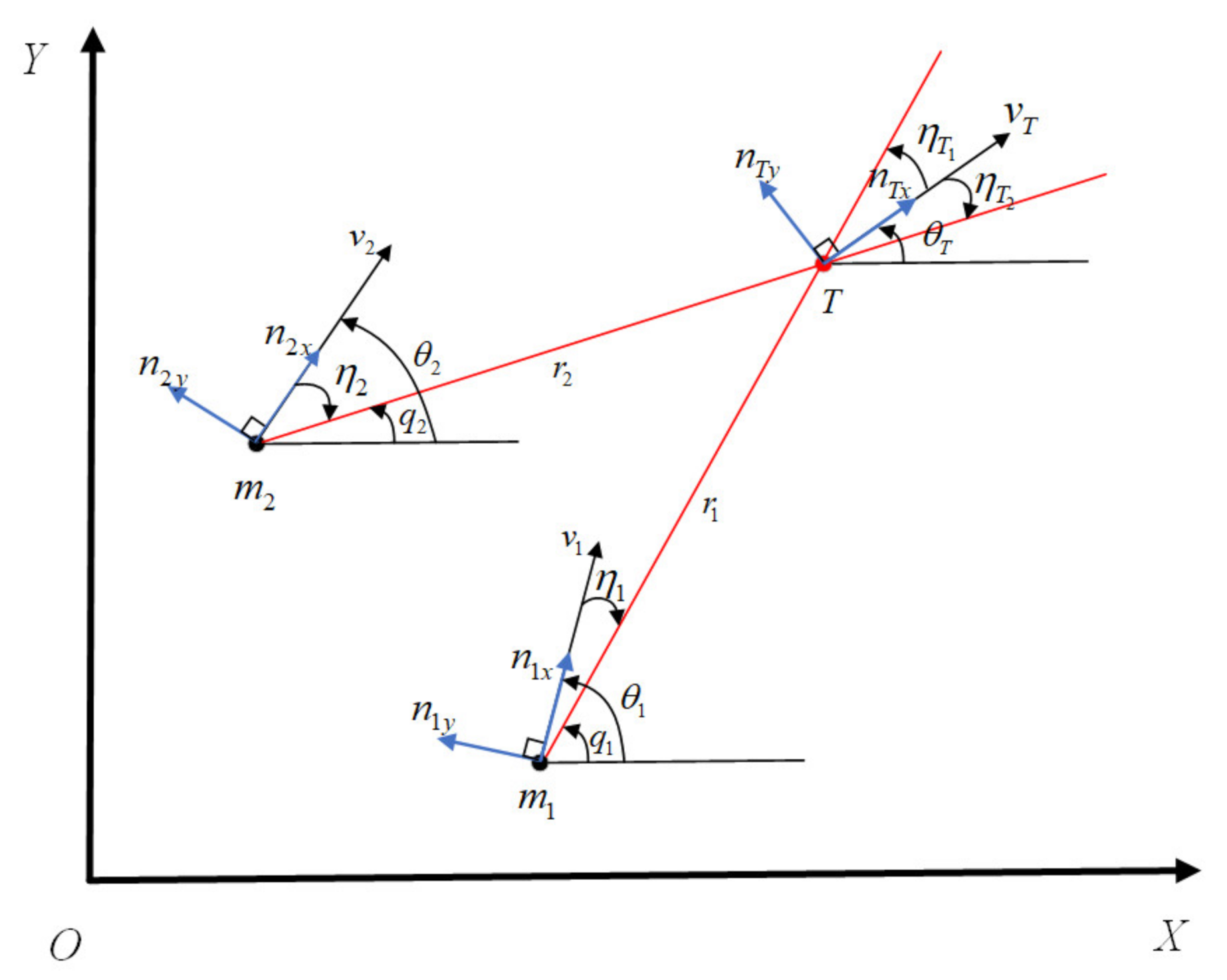
The geometric relationships in the guidance process are illustrated in
Figure 1 where
denotes the
i th UAV, and
T denotes the target.
The terms
stand for the LOS angle, leading angle, flight path angle, respectively. From the geometric relations in
Figure 1, we can obtain that
We note that a case
can be considered as an asymmetry of a case
. The case
is treated in this paper. The case pursued is made by
where
is the distance from
to the target;
represents the velocity of
, while
as well as
are the overloads of
in its velocity frame, tuning the magnitude and direction of
, and
stands for the leading angle and the velocity of the target.
Taking the derivative of
we can obtain that
Denote that
then we can obtain further
The remaining flight time
of the vehicle can be roughly estimated as
Taking the derivative of (10) and substituting (9) we can obtain
Taking the derivative of
, we can obtain
Note that
, and
then we can get
Illustrative Example. The purpose of the cooperative attack is to enable multiple UAVs to achieve a simultaneous attack on the target while ensuring their cooperation in terms of hitting angles. Simultaneous strikes can be achieved if and only if the remaining flight time achieves consensus. From (10), we can find that the remaining flight time of the UAV is determined by and . At the same time, we can see that if then the UAV is able to hit the target. Then we are able to obtain the following definition.
Definition 2. If the following equations hold simultaneously, the multi-UAVs system achieves a coordinated attack in finite time.
where
and
are default constants and
is a limited adjustment time.
4. Main Result
This section proposes a sliding-mode FDO to evaluate the interference caused by target maneuvers in finite time. After that, based on the finite-time consensus theory, and are designed to enable simultaneous multi-directional attacks against the target, respectively.
4.1. FDO Design
Inspired by [
29], the FDO is designed as
then the observation error are:
Theorem 1. If Assumption 2 holds, and the parameters satisfy that, then the disturbance observation errorandare able to converge in finite time.
Proof of Theorem 1. Define the Lyapunov function as:
Taking the time derivative of the above function, we can get
According to Lemma 3 we can obtain
We can obtain
from
then (18) can be rewritten as:
According to the finite-time stability theory in Lemma 2, if , we can obtain that in a finite time . By the structure of we can get that in a finite time , where . □
4.2. Impact Angle Cooperation Part
According to Definition 2, we get the purpose of impact angle cooperation is
This means that the purpose of the LOS angle cooperation is to make the LOS angles of different UAVs into a predefined sequence. The cooperative guidance law is also supposed to make the LOS angular rate of each UAV asymptotically equal to zero.
It follows from Equation (12) that its derivative satisfies
and the guidance law is designed as follows
Lemma 5. Under Assumption 1, there exists an appositive column vector, such thatfor all. Denotethen the matrixis symmetric.
Theorem 2. If the parameters in the guidance law (23) are satisfied, then the impact angle coordination condition (20) is achieved in finite-time.
Proof of Theorem 2. Substituting (23) into (22) yields
Let
with
,
and
of which
satisfies
and
. According to the algebraic properties of
, we have
and
if and only if
,
respectively. From (24) and (25) we obtain
where
. Consider a Lyapunov function candidate
where
. Noting that
and
have the same component sign, we are able to obtain
for any
. Furthermore, from
we know that
for any
. Therefore, we obtain
as a positive definition. Then the time derivative of the above function yields
From the definition of
in (8) and note that both
and
are bounded, we can get that
is bounded in
. Note that
is also bounded in
we can obtain that
is bounded in
and its upper bound is assumed to be
. It follows from (28) that:
Thus,
is bounded in
. When
, we get that
. Then we can receive that
It can be seen that implies . It can be seen from LaSalle’s invariance theorem that the system (26) can reach globally asymptotically stable for its zero equilibrium.
Next, we will prove that the system dynamics have a negative degree of homogeneity. Let
while the derivative of
is
. Consider the dilation
,
,
and homogeneity
then we can gain
We can find for every we have . By Lemma 4, we have holds by setting . According to Lemma 4, the system (26) can achieve global finite-time stability. Then the impact angle coordination condition (20) could be achieved in finite-time. We have completed the proof. □
4.3. Impact Time Cooperation Part
By Definition 2, the goal of time cooperation is
According to this goal, we design time cooperative guidance law as
Theorem 3. If the parameters in the guidance law (32) are satisfied, then the impact angle coordination condition (31) could be achieved in finite time.
Proof of Theorem 3. Substituting (32) into the system (11) we get
Let
then (33) can be rewritten as
where
,
and
. Let
. According to the algebraic properties of
, we have
if and only if
, respectively. Take the time derivative of the above function yields:
Consider a Lyapunov function candidate
. It is convenient to obtain that
is positive definite. Its derivative along (35) satisfies
Based on the definition of
and
, we are able to obtain that
is bounded in
. From Theorems 1 and 2, we are able to get
and
in
. Then (36) can be reformulated as
Notice that while and has the same sign component-wise, we can obtain and it can be seen that indicates that . It can be seen from LaSalle’s invariance theorem that the system (35) can reach globally asymptotically stable for its zero equilibrium.
Using the same analysis as in Theorem 2, we are able to obtain that the system (35) has a negative degree of homogeneity when . Then the impact time coordination condition (31) can be achieved in a finite time. □
Remark 1. For comparison, it is helpful to review the literature’s engagement models and guidance laws in References [
24,
25].
In Ref. [
24]
the derivative of is given as: A three-dimensional version is given in the literature [
25] as
By feedback linearization, the guidance law was designed in the literature [
24,
25] as
and
can be rewritten as
in this way. References [
24,
25] designed consensus-based DCGL to achieve simultaneous arrival based on this model. However, the overload command has critical singularities when
. Due to the singularities,
would diverge to infinity when
. The guidance law (32) does not use feedback linearization and therefore avoids singularities above.
5. Numerical Example
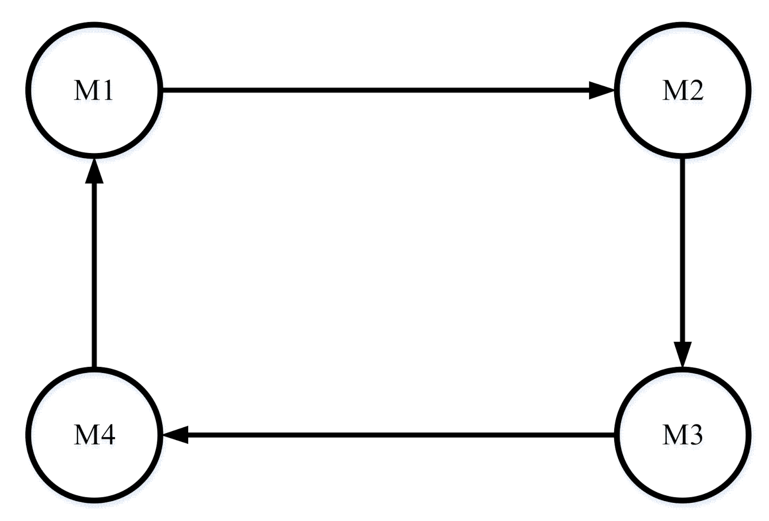
We verify the performance of the DCGL by a numerical example of attacking a maneuvering target by four UAVs. In which the speed of the target is 300 m/s. The target’s normal acceleration is set to
. The communication topology of the vehicles is shown in
Figure 2.
The initial conditions of multiple UAVs are shown in
Table 1.
For the FDO, the parameters are set to be . The parameters of the guidance law in the normal direction of LOS are set as . Further, the guidance law parameters for the LOS direction are chosen as .
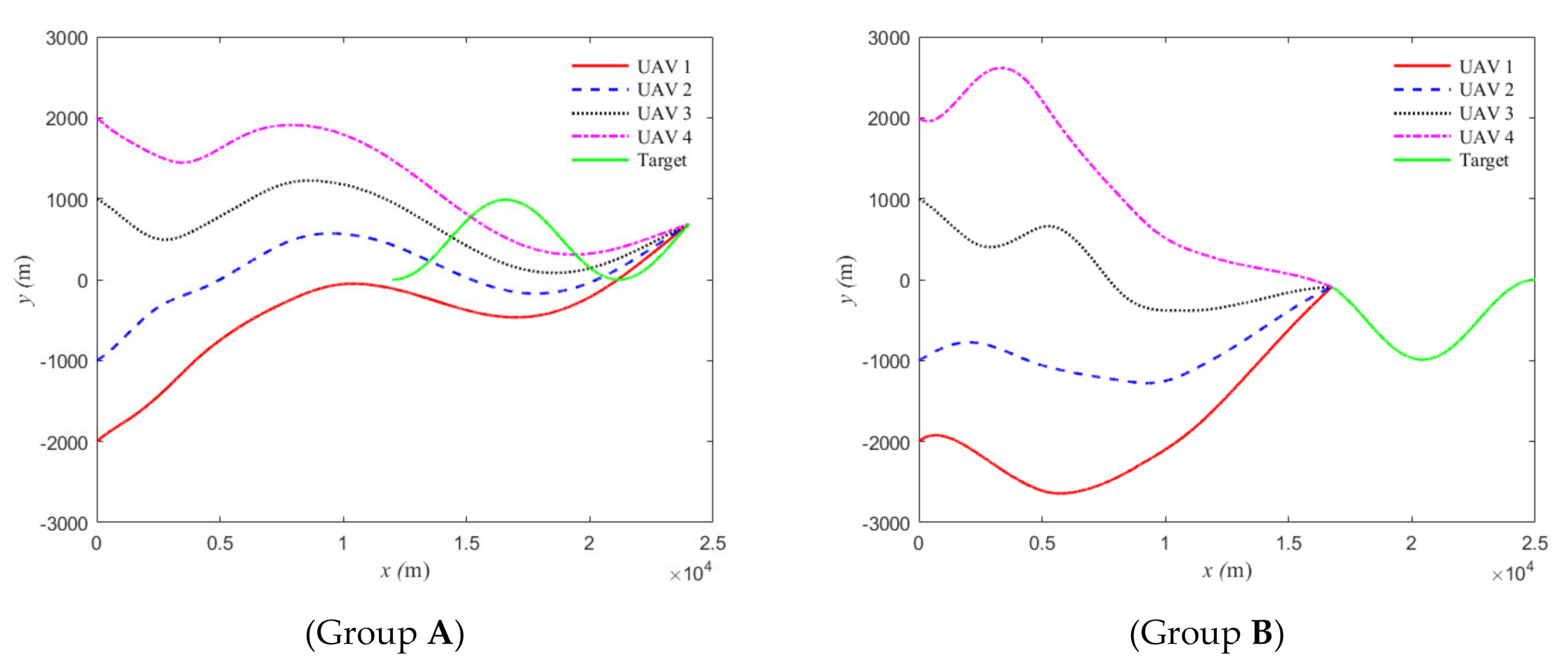
5.1. Simulation of Pursuit and Head-On Attacks
We set up two sets of simulations, where group A is a chase attack and group B is a head-on attack. The initial position of the target in group A is (12,000, 0) and the initial orientation is the initial heading angle of the target is 0°. Group B target’s initial position is (25,000, 0) the initial heading angle of the target is 180°.
The simulation curves of the suggested cooperative guidance law, including the trajectories of the vehicles and the target, time-to-go of four UAVs to attack a maneuvering target, impact angle, LOS angular rate, radial relative velocities, actual and estimated values of external disturbance, and tangential and normal acceleration command, are shown in
Figure 3,
Figure 4,
Figure 5,
Figure 6,
Figure 7,
Figure 8,
Figure 9 and
Figure 10.
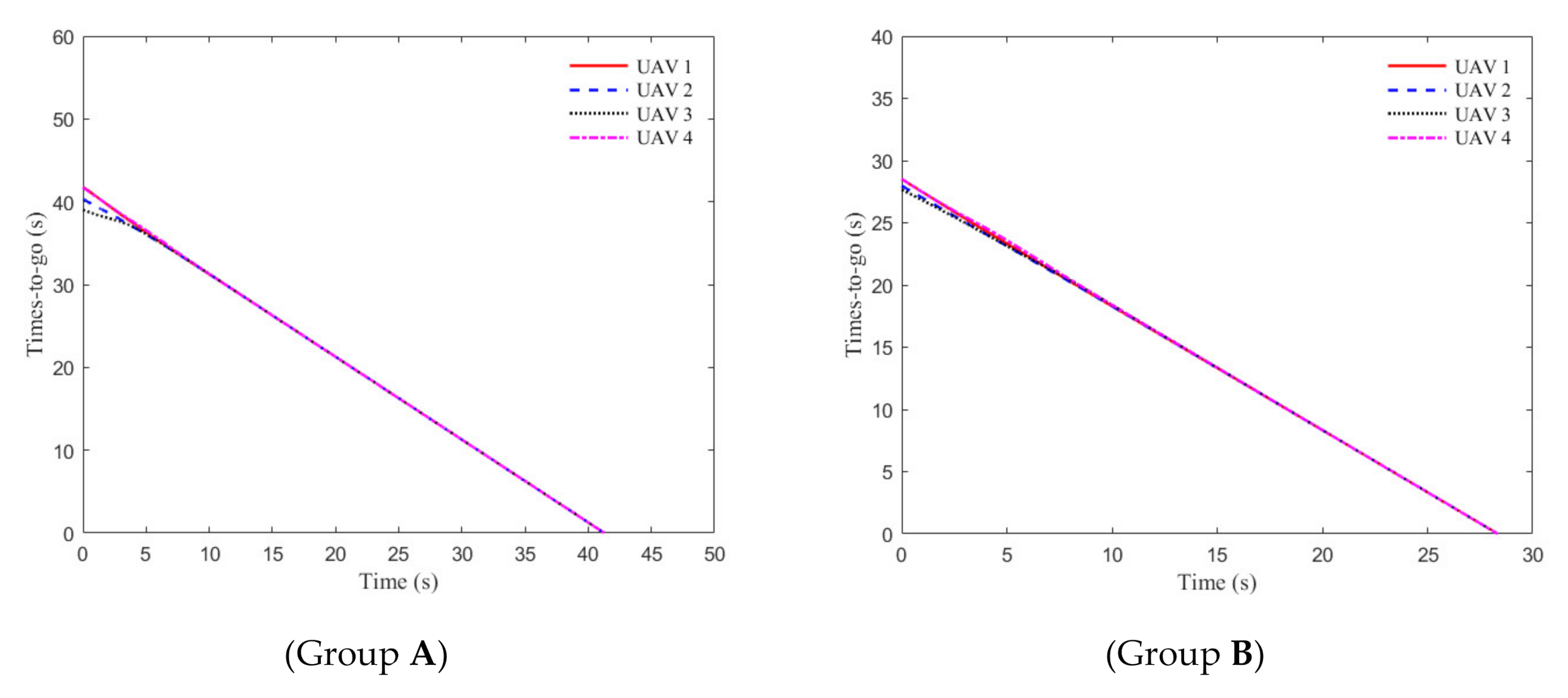
In
Figure 3 and
Figure 4, it can be seen that the four UAVs achieve a simultaneous attack on a maneuvering target. In addition, it can be observed in
Figure 4 that the four UAVs have different remaining flight times at moment zero. However, using the designed finite-time consensus protocol (34), the remaining flight time reaches the same value after approximately 10 seconds.
Figure 5 shows that the relative velocity between the UAVs and the target converges to fixed values after some time. At the same time, the relative velocities of the different UAVs and the target do not converge to the same value, which avoids unnecessary energy consumption.
Figure 6 and
Figure 7 indicate that under the angular cooperative guidance law (25), the LOS angle converges to the desired sequence after some time, while the LOS angle rate converges to zero.
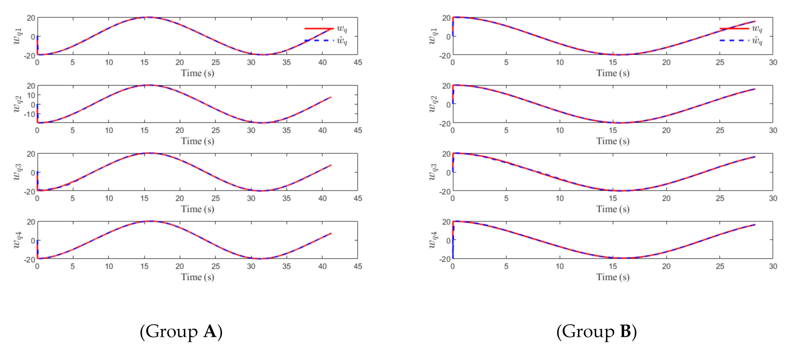
As shown in
Figure 8 and
Figure 9, the proposed FDO (15) has a favorable performance in estimating the disturbance caused by the unknown maneuvers of the target.
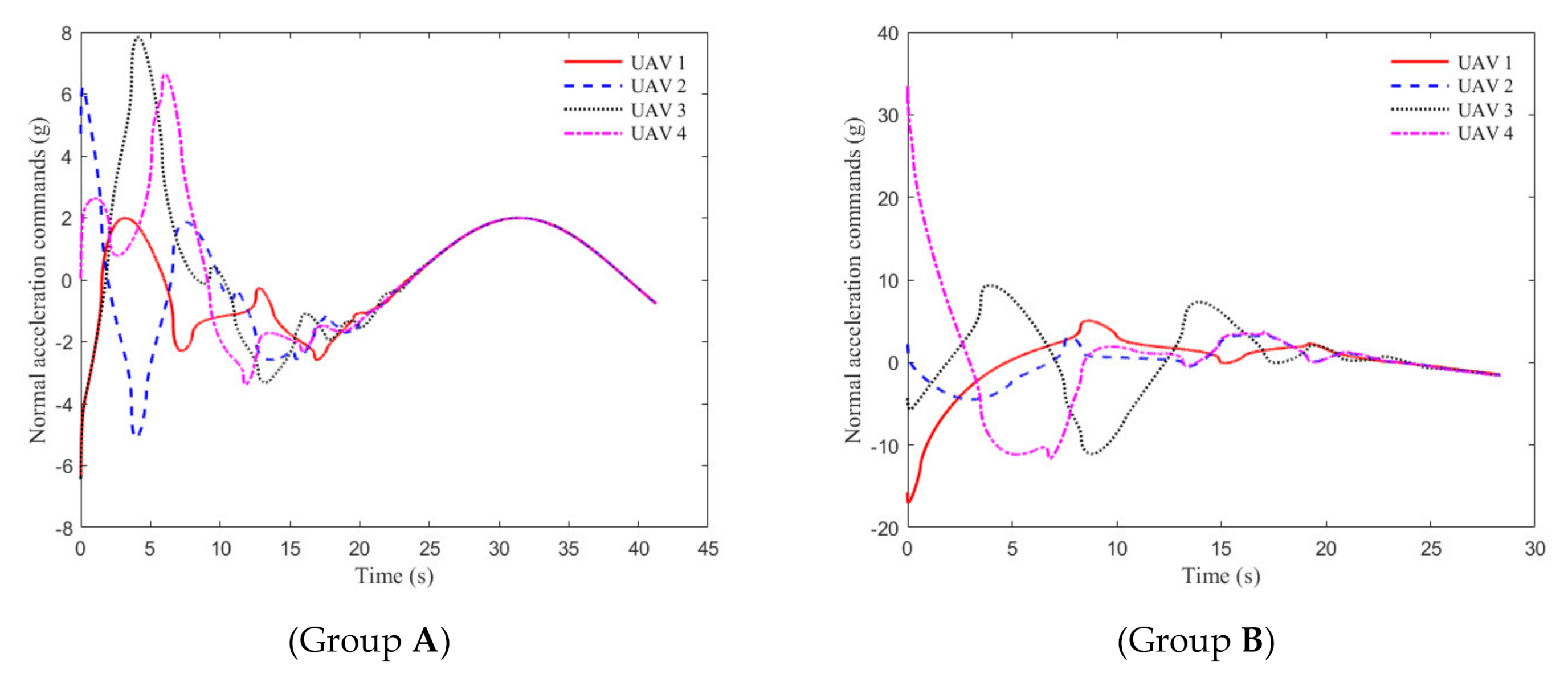
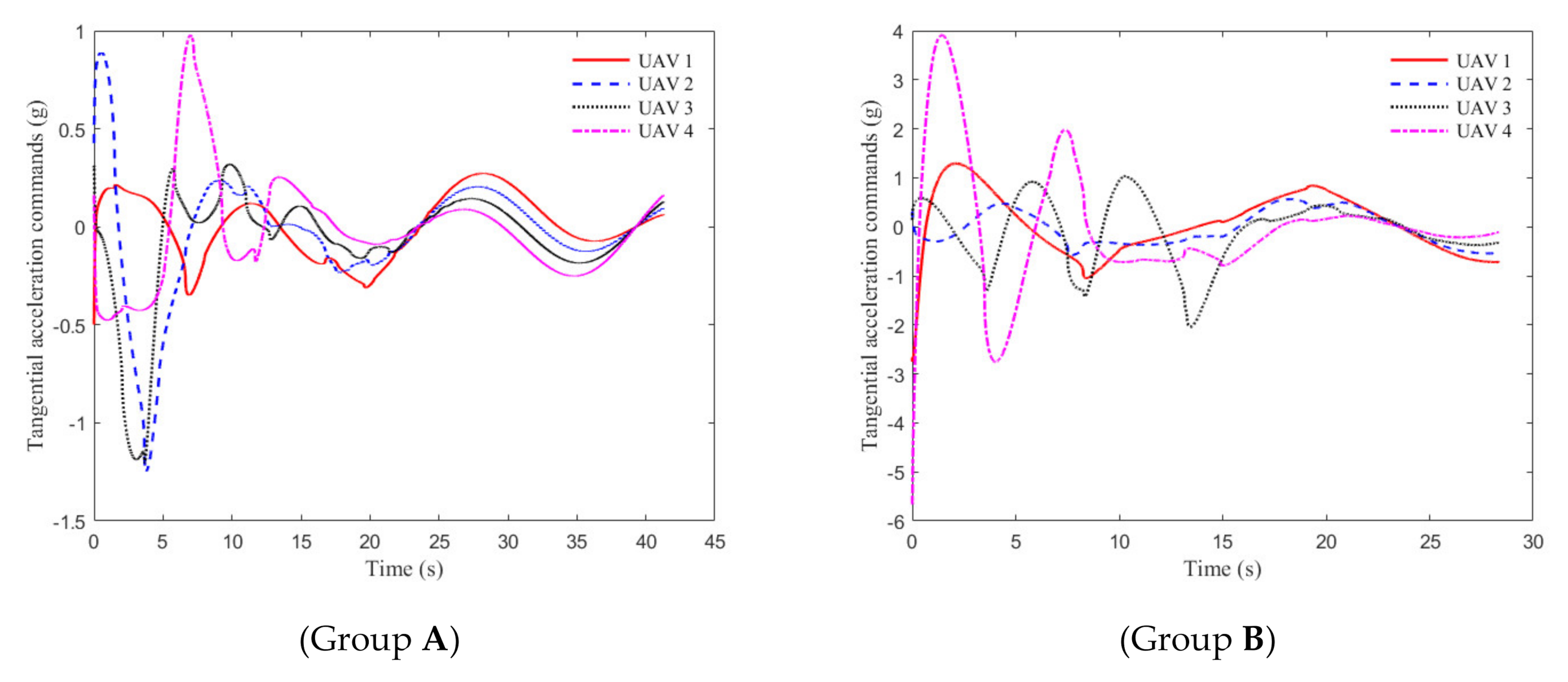
Figure 10 and
Figure 11 show that both the tangential acceleration commands and normal acceleration commands are smooth.
5.2. Comparison with Feedback Linearization Methods
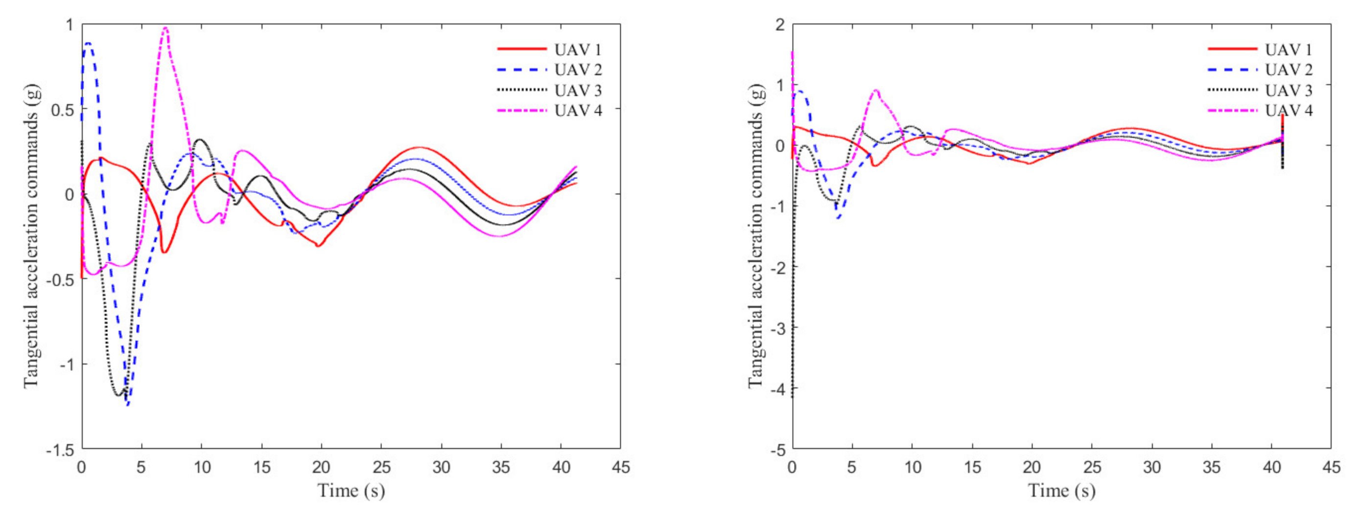
We compared the tangential acceleration commands of the two methods for the initial condition A. From the
Figure 12 we can see that the required overload command of the proposed method is significantly smaller. From the right-hand image, we can see that the required acceleration at the initial moment is large at around
. At the same time, the acceleration required for the proposed method is less than
. This is due to the fact that
needs to be compensated directly in the feedback linearization method. Usually,
does not converge to zero at the initial moment and
is large at the same time, therefore resulting in a large overload command. At the same time, we can see that the feedback linearization method has a significantly higher acceleration command at the moment of hit. This is because the acceleration command includes
. This leads that the overload command has critical singularities when
. Through comparison, it can be seen that the proposed method in this paper has a smaller overload command and is more promising for application.
Figure 12.
Comparison of overload commands.
Figure 12.
Comparison of overload commands.
7. Annexes
A directed graph is developed for N agents to represent the interactions between agents, the vertex set and the edge set. Moreover, edges are an ordered pair of vertices , implying that agent j can receive information from agent i. If a directed edge from i to j exists, then i would be defined as the parent node, and j would be defined as the child node, the neighbors of node i are represented by and are the neighbor numbers of agent i.
The adjacency matrix A associated with is defined such that if and node i is neighboring to node j, while otherwise. For a directed graph , and therefore the matrix A is asymmetric. The Laplacian matrix of the graph associated with adjacency matrix A is given as , where and .


