
Hover Performance Analyses of Coaxial Co-Rotating Rotors for eVTOL Aircraft


Abstract
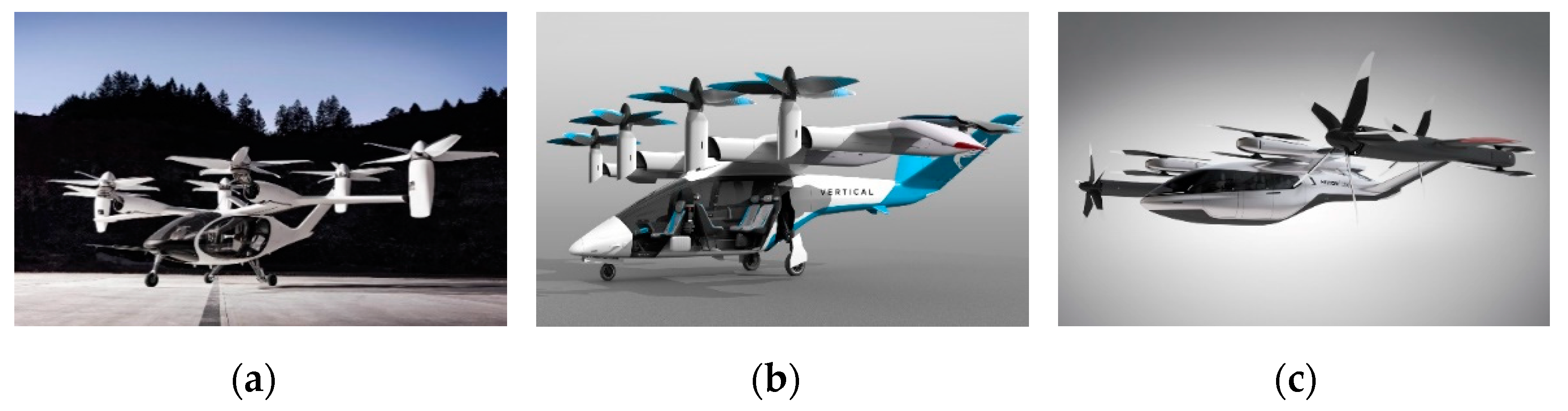
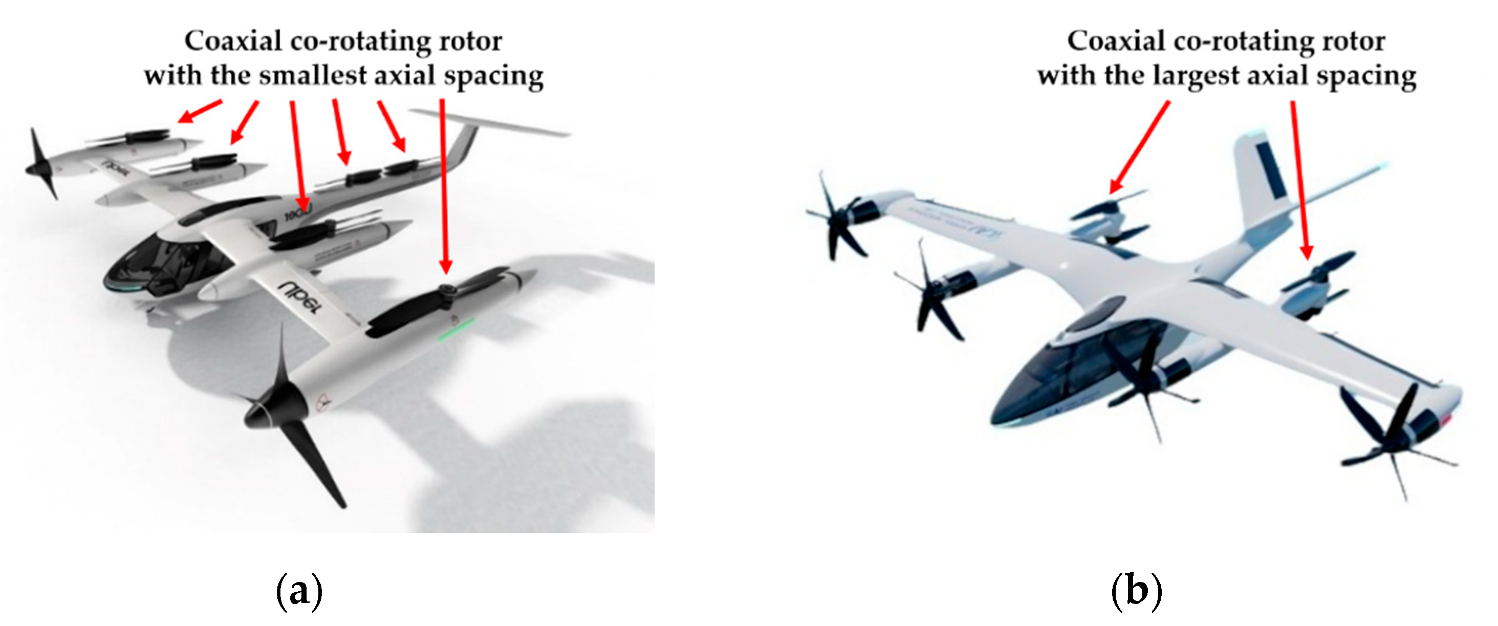
:1. Introduction
2. Analytical Methods
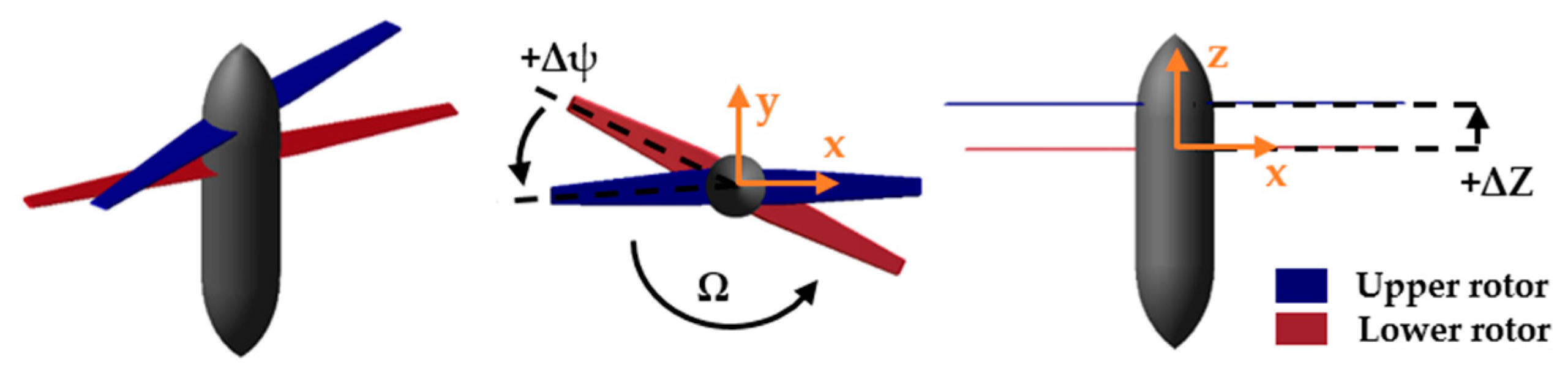
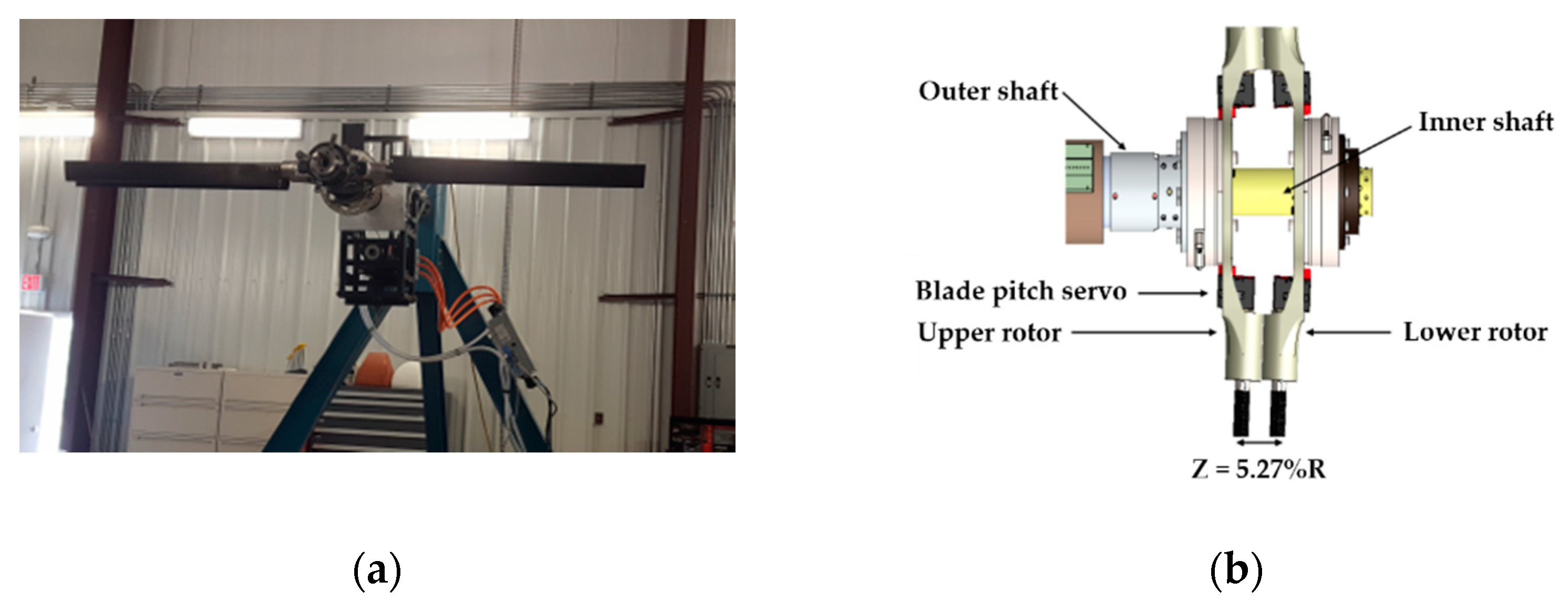
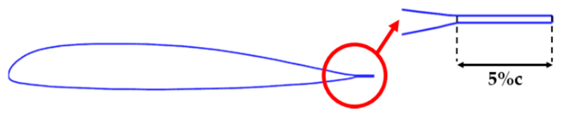
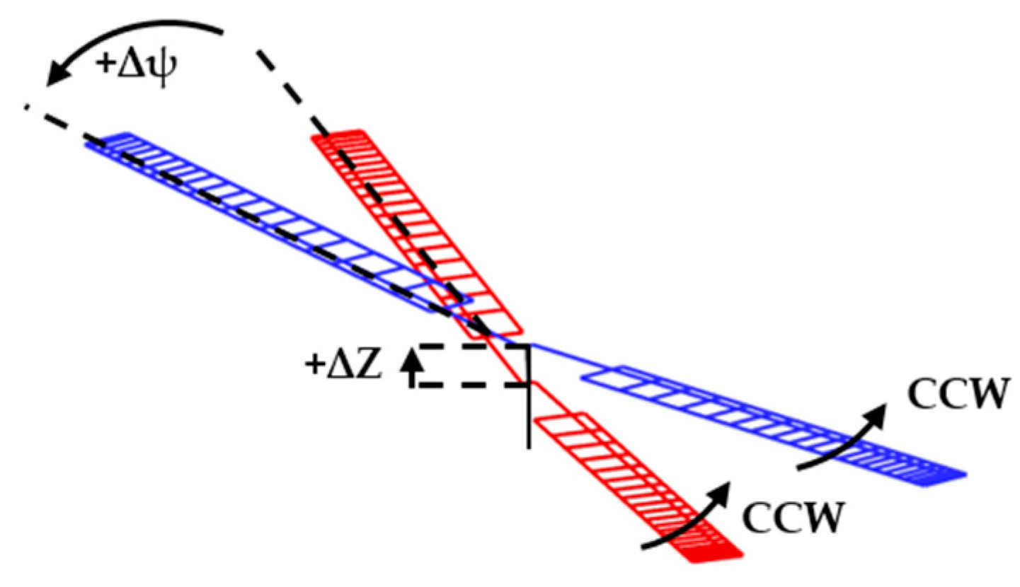
2.1. Baseline Model for a Coaxial Co-Rotating Rotor
2.2. Aeromechanics Modeling and Analytical Techniques
3. Results
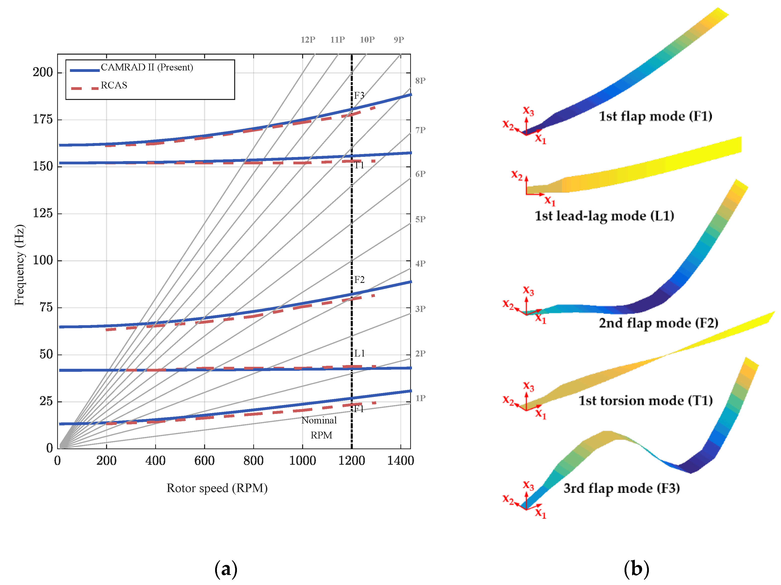
3.1. Fan Plot Analyses
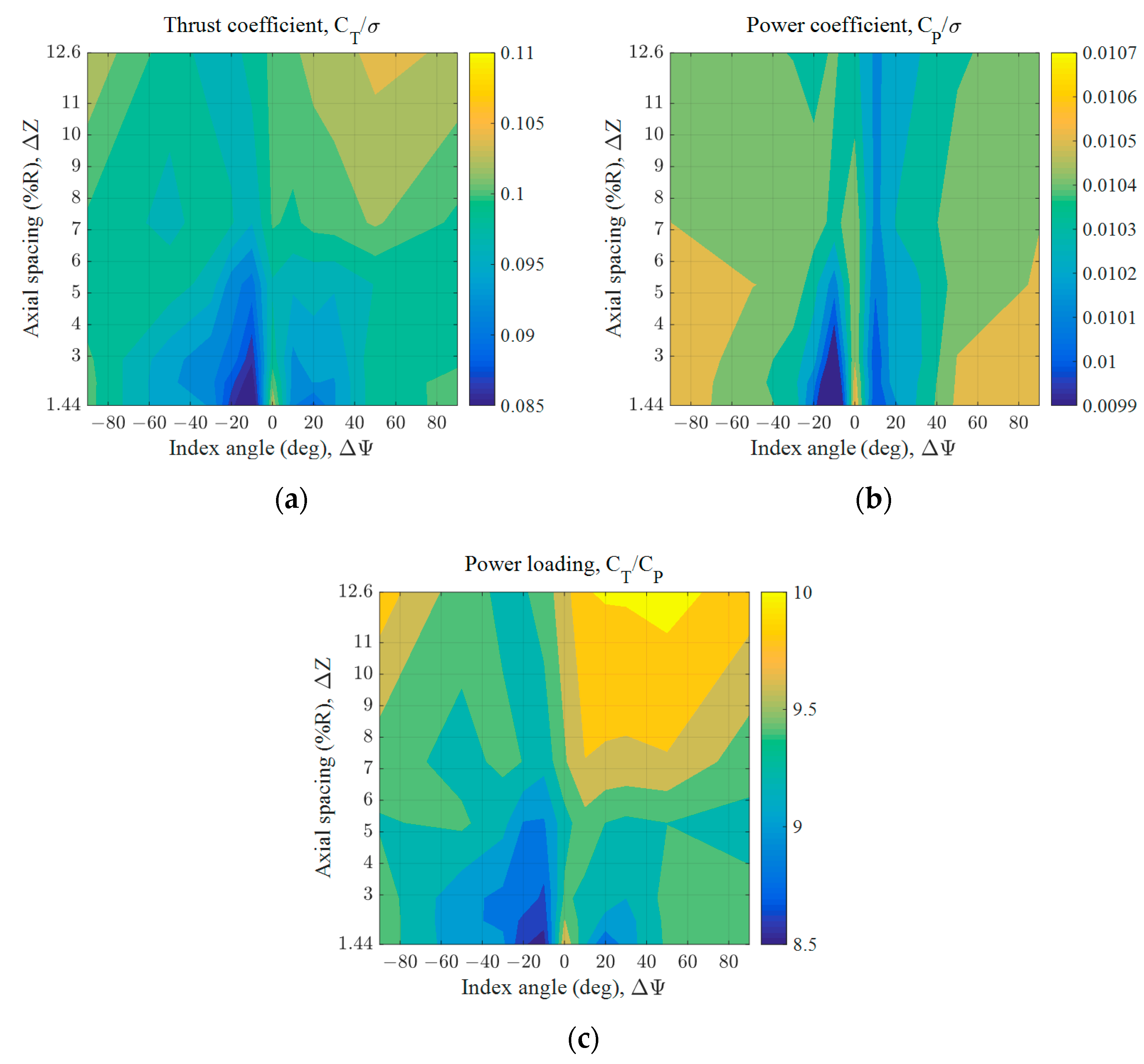
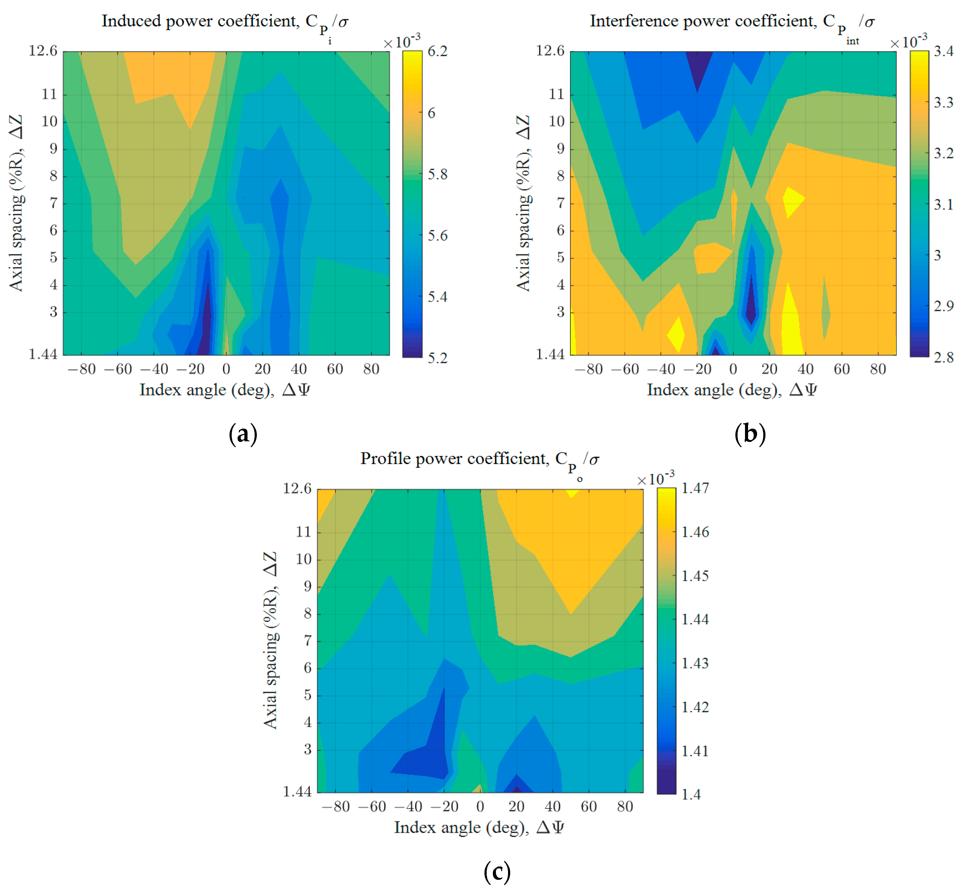
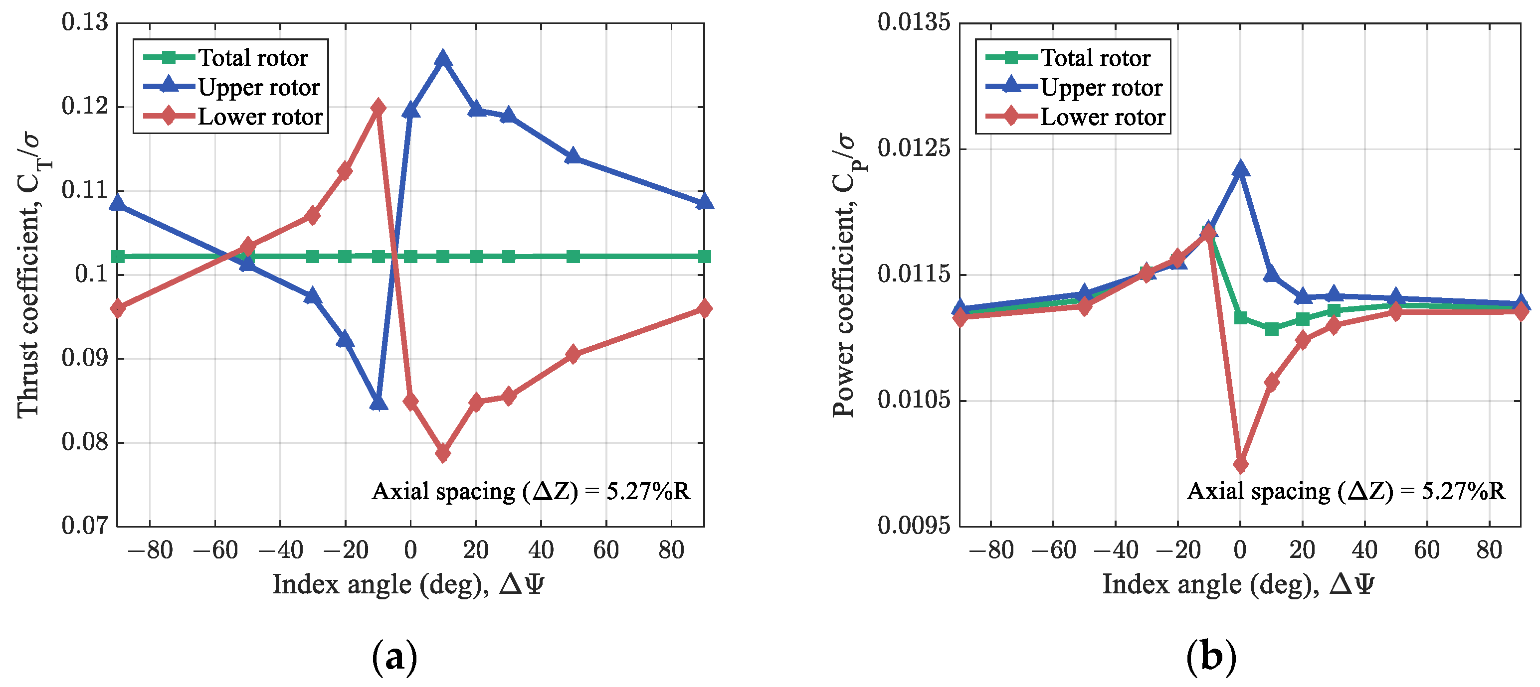
3.2. Hover Performance Analyses without Trim Techniques
3.3. Hover Performance Analyses with Trim Techniques
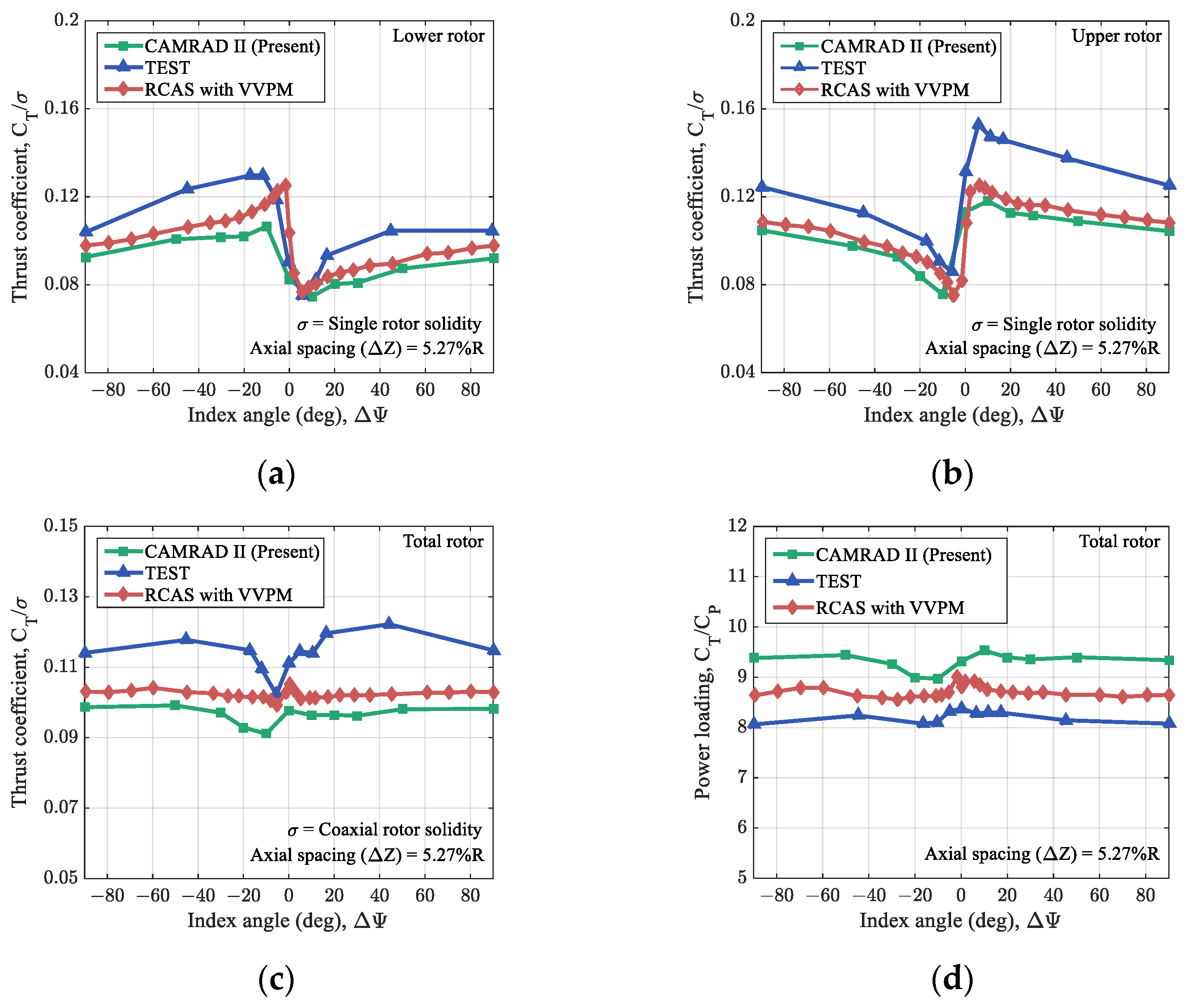
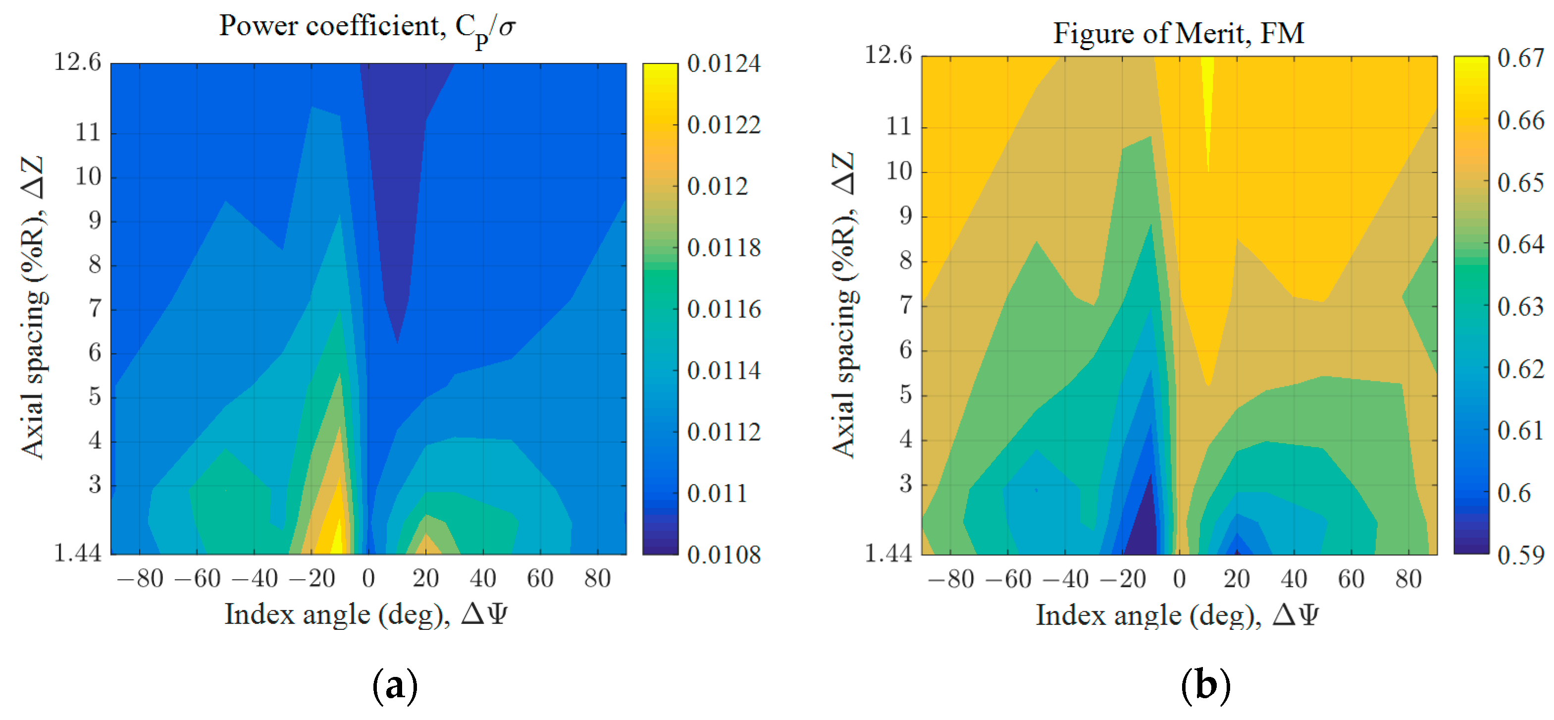
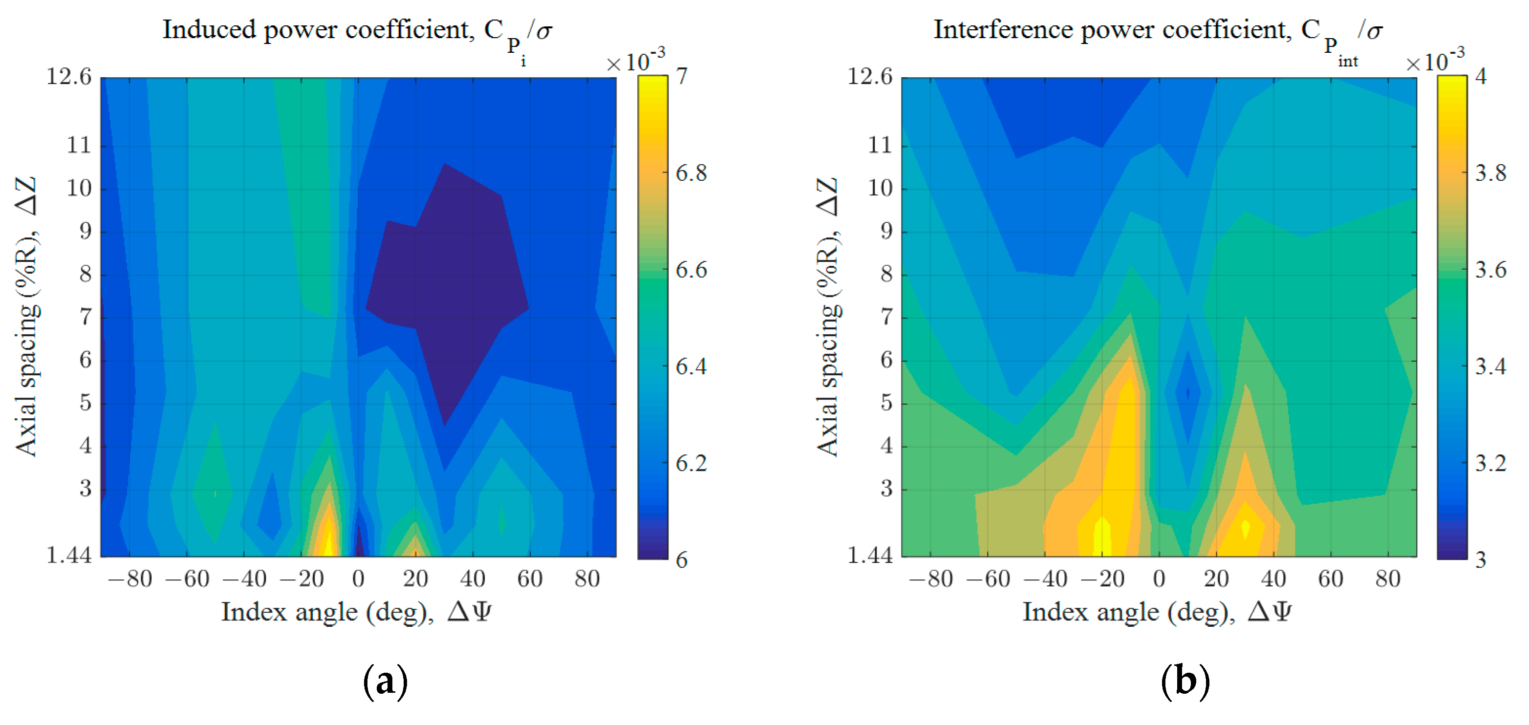
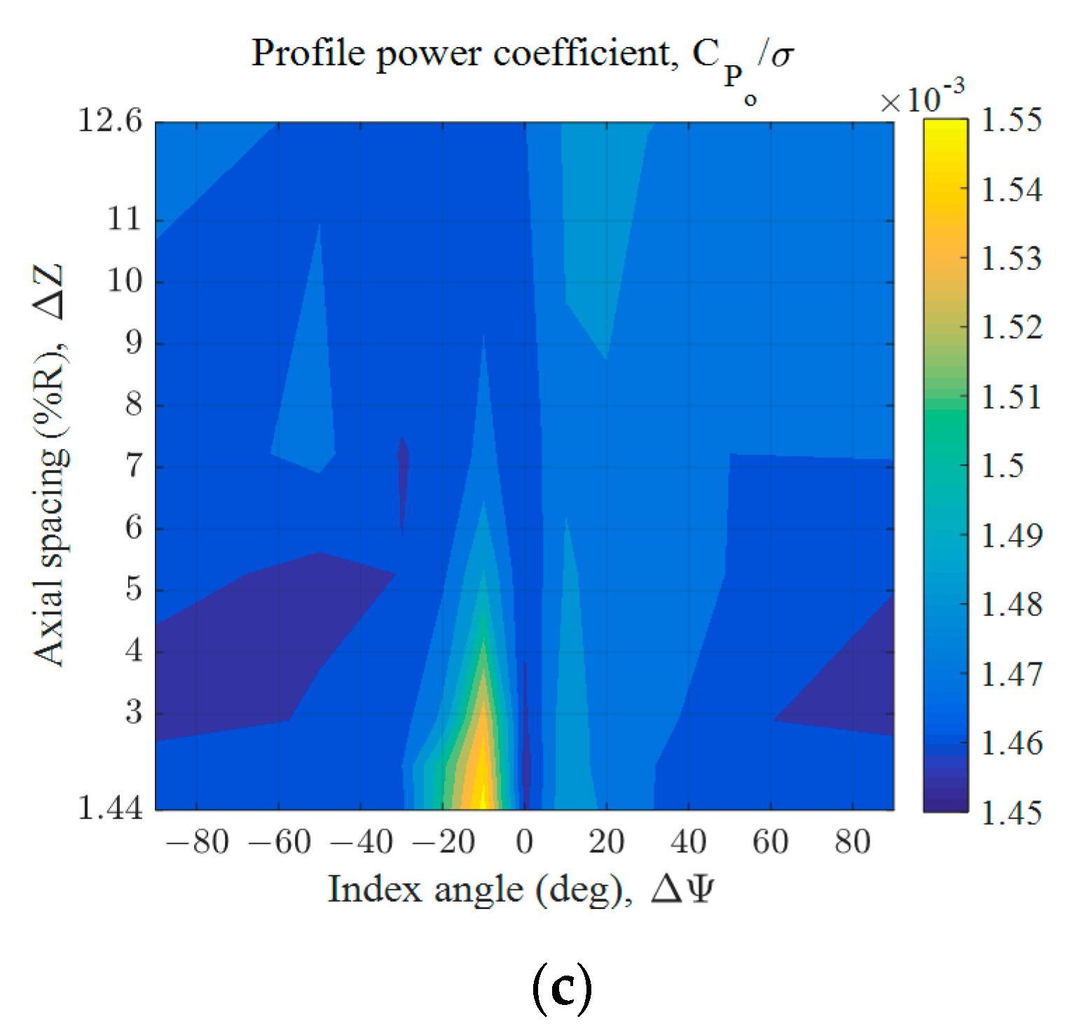
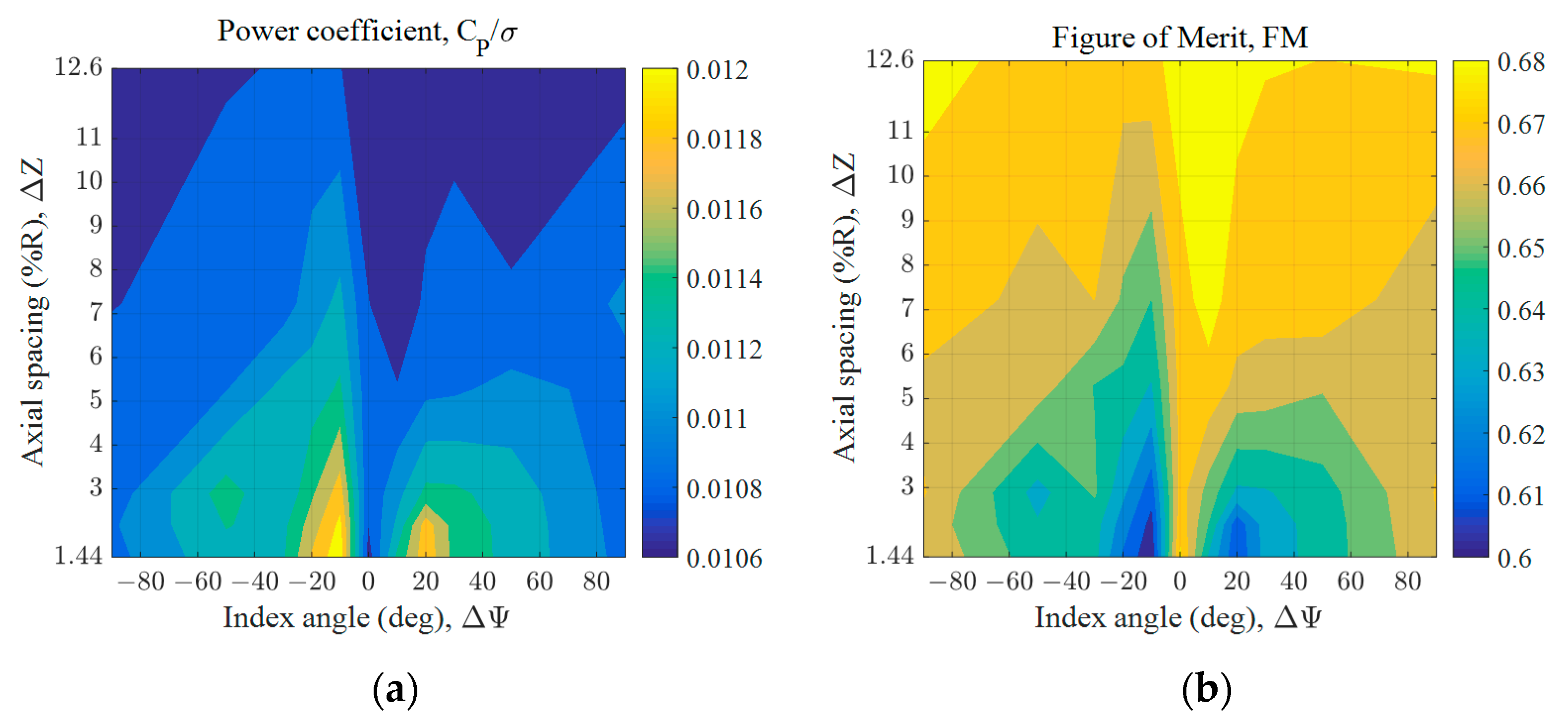
3.3.1. Hover Performance Analyses
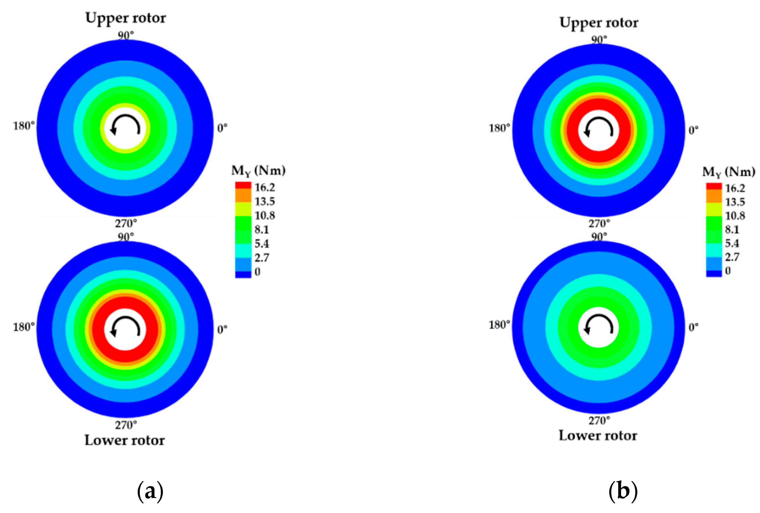
3.3.2. Blade Load Analyses
3.3.3. Effect of the Taper Ratio on Hover Performance
3.3.4. Effect of the Built-In Twist on Hover Performance
4. Conclusions
Author Contributions
Funding
Institutional Review Board Statement
Informed Consent Statement
Data Availability Statement
Conflicts of Interest
Nomenclature
| R | Rotor radius, m |
| c | Blade chord length, m |
| σ | Coaxial rotor solidity |
| ΔΨ | Index angle, deg |
| ΔZ | Axial spacing, %R |
| MY | Flap bending moment, Nm |
| M | Local Mach number |
| Cl | Sectional lift force coefficient |
| CT | Rotor thrust coefficient |
| CP | Rotor power coefficient |
| CPi | Rotor induced power coefficient |
| CPint | Rotor interference power coefficient |
| CPo | Rotor profile power coefficient |
| CT/CP | Rotor power loading |
| FM | Rotor Figure of Merit |
References
- Johnson, C.; Sirohi, J.; Jacobellis, G.; Singh, R.; McDonald, R. Investigation of stacked rotor performance in hover part 1: Experimental measurements. In Proceedings of the VFS Aeromechanics for Advanced Vertical Flight Technical Meeting, San Jose, CA, USA, 21–23 January 2020. [Google Scholar]
- The Electric VTOL NewsTM. Available online: https://evtol.news/ (accessed on 7 December 2021).
- Bain, J.; Mikić, G.V.; Stoll, A. Aerodynamic and acoustic design of the Joby aviation eVTOL propeller. In Proceedings of the Vertical Flight Society’s 77th Annual Forum and Technology Display, Virtual, 10–14 May 2021. [Google Scholar]
- Holden, J.; Goel, N. Fast-forwarding to a future of on-demand urban air transportation. In Proceedings of the UBER Elevate, San Francisco, CA, USA, 27 October 2016. [Google Scholar]
- Sorensen, P.; Cuppoletti, D.R. Rotor-rotor interaction noise of counter-rotating vs. co-rotating rotors for air mobility applications. In Proceedings of the AIAA SCITECH 2022 Forum, San Diego, CA, USA, 3–7 January 2022. [Google Scholar]
- Antcliff, K.; Whiteside, S.; Kohlman, L.W.; Silva, C. Baseline assumptions and future research areas for urban air mobility vehicles. In Proceedings of the AIAA SCITECH 2019 Forum, San Diego, CA, USA, 7–11 January 2019. [Google Scholar]
- Pollard, B.; Patterson, M.D.; Whiteside, S. A combined blade element and vortex panel method for stacked rotor analysis. In Proceedings of the AIAA AVIATION Forum, Dallas, TX, USA, 17–21 June 2019. [Google Scholar]
- Tinney, C.E.; Valdez, J. Thrust and Acoustic Performance of Small-Scale, Coaxial, Corotating Rotors in Hover. AIAA J. 2020, 58, 1657–1667. [Google Scholar] [CrossRef]
- Platzer, S.; Hajek, M.; Rauleder, J.; Mortimer, P.; Sirohi, J. Investigation of the flow fields of coaxial stacked and counter-rotating rotors using PIV measurements and URANS simulations. In Proceedings of the Vertical Flight Society’s 77th Annual Forum and Technology Display, Virtual, 10–14 May 2021. [Google Scholar]
- Valdez, J.A.; Tinney, C.E. The unsteady wake produced by a coaxial co-rotating rotor in hover. In Proceedings of the AIAA SCITECH 2022 Forum, San Diego, CA, USA, 3–7 January 2022. [Google Scholar]
- Kunz, D.L.; Newkirk, M.C. A Generalized Dynamic Balancing Procedure for the AH-64 Tail Rotor. J. Sound Vib. 2009, 326, 353–366. [Google Scholar] [CrossRef]
- Jacobellis, G.; Singh, R.; Johnson, C.; Sirohi, J. Experimental and computational investigation of stacked rotor broadband noise in hover. In Proceedings of the VFS 77th Annual Forum, Virtual, 10–14 May 2021. [Google Scholar]
- Misiorowski, M.; Gandhi, F.; Anusonti-Inthra, P. Comparison of acoustic predictions using distributed and compact airloads. In Proceedings of the Vertical Flight Society 75th Annual Forum and Technology Display, Philadelphia, PA, USA, 13–16 May 2019. [Google Scholar]
- Bhagwat, M. Co-rotating and counter-rotating coaxial rotor performance. In Proceedings of the AHS Specialists’ Conference on Aeromechanics Design for Transformative Vertical Flight, San Francisco, CA, USA, 16–18 January 2018. [Google Scholar]
- Whiteside, S.K.S.; Zawodny, N.S.; Fei, X.; Pettingill, N.A.; Patterson, M.D.; Rothhaar, P.M. An exploration of the performance and acoustic characteristics of UAV-scale stacked rotor configurations. In Proceedings of the AIAA SCITECH 2019 Forum, San Diego, CA, USA, 7–11 January 2019. [Google Scholar]
- Uehara, D.; Sirohi, J.; Bhagwat, M.J. Hover Performance of Corotating and Counterrotating Coaxial Rotors. J. Am. Helicopter Soc. 2020, 65, 1–8. [Google Scholar] [CrossRef]
- Uehara, D.; Sirohi, J. Quantification of swirl recovery in a coaxial rotor system. In Proceedings of the AHS International 73rd Annual Forum & Technology Display, Fort Worth, TX, USA, 9–11 May 2017. [Google Scholar]
- Ramasamy, M. Hover Performance Measurements toward Understanding Aerodynamic Interference in Coaxial, Tandem, and Tilt Rotors. J. Am. Helicopter Soc. 2015, 60, 1–17. [Google Scholar] [CrossRef]
- Brazinskas, M.; Prior, S.D.; Scanlan, J.P. An Empirical Study of Overlapping Rotor Interference for a Small Unmanned Aircraft Propulsion System. Aerospace 2016, 3, 32. [Google Scholar] [CrossRef]
- Jacobellis, G.; Singh, R.; Johnson, C.; Sirohi, J.; McDonald, R. Experimental and Computational Investigation of Stacked Rotor Performance in Hover. Aerosp. Sci. Technol. 2021, 116, 106847. [Google Scholar] [CrossRef]
- Jacobellis, G.; Singh, R.; Johnson, C.; Sirohi, J.; McDonald, R. Investigation of stacked rotor performance in hover pt. II: Computational validation. In Proceedings of the AHS Aeromechanics Specialists’ Meeting, San Jose, CA, USA, 21–23 January 2020. [Google Scholar]
- Saberi, H.; Khoshlahjeh, M.; Ormiston, R.A.; Rutkowski, M.J. Overview of RCAS and application to advanced rotorcraft problems. In Proceedings of the AHS 4th Decennial Specialist’s Conference on Aeromechanics, San Francisco, CA, USA, 21–23 January 2004. [Google Scholar]
- Johnson, W. CAMRAD II, Comprehensive Analytical Model of Rotorcraft Aerodynamics and Dynamics; Johnson Aeronautics: Palo Alto, CA, USA, 1992. [Google Scholar]
- Lee, Y.-B.; Park, J.-S. Study on Performance Analyses on Coaxial Co-Rotating Rotors of e-VTOL Aircraft for Urban Air Mobility. J. Korean Soc. Aeronaut. Space Sci. 2021, 49, 1011–1018. [Google Scholar] [CrossRef]
- Schmaus, J.H. Aeromechanics of a High Speed Coaxial Helicopter Rotor. Ph.D. Thesis, University of Maryland, College Park, MD, USA, 2017. [Google Scholar]
- Drela, M. A User’s Guide to MSES 3.05; MIT Department of Aeronautics and Astronautics: Cambridge, MA, USA, 2007. [Google Scholar]
- XFLR5. Analysis of Foils and Wings Operating at Low Reynolds Numbers; XFLR5 v6.02 Guidelines; MIT Aerospace Computational Design Laboratory: Cambrige, MA, USA, 2013. [Google Scholar]
- Lim, J.W.; McAlister, K.W.; Johnson, W. Hover Performance Correlation for Full-Scale and Model-Scale Coaxial Rotors. J. Am. Helicopter Soc. 2009, 54, 32005. [Google Scholar] [CrossRef]
- Go, J.-I.; Kim, D.-H.; Park, J.-S. Performance and Vibration Analyses of Lift-Offset Helicopters. Int. J. Aerosp. Eng. 2017, 2017, 1865751. [Google Scholar] [CrossRef] [Green Version]
- Leishman, G.J. Principles of Helicopter Aerodynamics; Cambridge University Press: Cambridge, UK, 2006. [Google Scholar]


| Property | Value |
|---|---|
| Hub type | Hingeless |
| Number of blades per rotor | 2 |
| Rotor radius, R (m) | 1.108 |
| Chord length, c (m) | 0.080 |
| Root cutout (%R) | 18.76 |
| Nominal rotor speed (RPM) | 1200 |
| Coaxial rotor solidity, σ | 0.1 |
| Airfoil | VR-12 with a tab |
| Taper ratio | 1.0 |
| Built-in twist angle (deg) | 0.0 |
| Pre-cone angle (deg) | 3.0 |
| Parameter | Value |
|---|---|
| Index angle, ΔΨ (deg) | 0, 10, 20, 30, 50, 90 |
| Axial spacing, ΔZ (%R) | 1.44, 2.17, 2.90, 5.27, 7.22, 12.60 |
Publisher’s Note: MDPI stays neutral with regard to jurisdictional claims in published maps and institutional affiliations. |
© 2022 by the authors. Licensee MDPI, Basel, Switzerland. This article is an open access article distributed under the terms and conditions of the Creative Commons Attribution (CC BY) license (https://creativecommons.org/licenses/by/4.0/).
Share and Cite
Lee, Y.-B.; Park, J.-S. Hover Performance Analyses of Coaxial Co-Rotating Rotors for eVTOL Aircraft. Aerospace 2022, 9, 152. https://doi.org/10.3390/aerospace9030152
Lee Y-B, Park J-S. Hover Performance Analyses of Coaxial Co-Rotating Rotors for eVTOL Aircraft. Aerospace. 2022; 9(3):152. https://doi.org/10.3390/aerospace9030152
Chicago/Turabian StyleLee, Yu-Been, and Jae-Sang Park. 2022. "Hover Performance Analyses of Coaxial Co-Rotating Rotors for eVTOL Aircraft" Aerospace 9, no. 3: 152. https://doi.org/10.3390/aerospace9030152