Article

Design and Simulation Analysis of an Electromagnetic Damper for Reducing Shimmy in Electrically Actuated Nose Wheel Steering Systems

1
State Key Laboratory of Mechanics and Control of Mechanical Structures, College of Aerospace Engineering, Nanjing University of Aeronautics and Astronautics, Nanjing 210016, China
2
Nanjing Engineering Institute of Aircraft Systems, Jincheng Corporation, AVIC (NEIAS), Nanjing 211106, China
*
Author to whom correspondence should be addressed.
Aerospace 2022, 9(2), 113; https://doi.org/10.3390/aerospace9020113
Submission received: 24 January 2022 / Revised: 11 February 2022 / Accepted: 16 February 2022 / Published: 19 February 2022

Abstract

:
Based on the technical platform of electrically actuated nose wheel steering systems, a new type of damping shimmy reduction technology is developed to break through the limitations of traditional hydraulic damping shimmy reduction methods, and an electrically actuated nose wheel steering structure scheme is proposed. The mathematical model of the electromagnetic damper is established, the derivation of skin depth, damping torque and damping coefficient is completed, and the design of the shape and size of the electromagnetic damper is combined with the derivation results and the technical index of shimmy reduction. The electromagnetic field finite element simulation results show that the mathematical modeling method of the electromagnetic damper has good accuracy, and its application to the shimmy reduction module of the electrically actuated nose wheel steering system is also feasible and superior. Finally, the key factors influencing the performance of electromagnetic damper shimmy reduction are studied and analyzed, thus forming a complete electromagnetic damper shimmy reduction technology for the electrically actuated system, and laying the foundation for the design of novel all-electric aircraft and landing gear.

1. Introduction

The concept of more-electric aircraft or even all-electric aircraft has been proposed and rapidly developed in order to improve energy efficiency, cut operating costs and reduce the take-off weight. In the process of progressive replacement of mechanical, hydraulic or pneumatic power sources by electromechanical actuators (EMA) [1], the validation of electromechanical nose wheel steering mechanisms has already started worldwide. In 2009, a project called Distributed and Redundant Electro-mechanical nose wheel Steering System (DRESS), jointly completed by several European aviation industry units, predicted that electromechanical integration may significantly improve the reliability and availability of nose wheel steering mechanisms [2]. In 2010, Bennett applied a fault-tolerant electromechanical actuator to the aircraft nose wheel steering system and theoretically investigated and experimentally validated it [3]. In 2010, Liao et al. studied the all-electric nose wheel steering system and introduced a design method for an electric turning control system for small aircraft landing gear based on DSP, which was experimentally verified to have the advantages of miniaturization, reliability and control flexibility [4].
Landing gear shimmy is a kind of self-excited vibration dominated by the oscillation of the wheels [5]. Understanding the shimmy phenomenon and proposing reasonable shimmy reduction measures have been a pressing problem for experts in aircraft structural dynamics, all-electric aircraft are no exception. Currently, the most effective measure to cope with the phenomenon of aircraft landing gear shimmy is the installation of a shimmy damper [6]. Dampers enable most aircraft to eliminate shimmy, or to improve shimmy problems. Most modern aircrafts use oleo dampers, except for some small aircraft and helicopters with dry friction dampers on the tail landing gear. In recent years, the rapid development of magnetorheological dampers has led to the research on landing cushioning as well as shimmy control using magnetorheological fluids. In 2021, Luong and Jo et al. mounted magnetorheological dampers on the aircraft landing gear to reduce landing impact. They also designed an intelligent controller based on supervised neural networks and verified the performance and stability of the magnetorheological dampers by crash tests [7,8]. In 2010, Chen et al. used magnetorheological dampers to suppress aircraft landing gear shimmy and designed a semi-active control strategy [9]. In 2019, Zhu et al. optimized the structure of an external magnetorheological damper on the aircraft landing gear and verified its shimmy reduction performance by means of damping characteristics tests [10]. In addition, with the development of electromechanical technology, electromagnetic dampers are proposed to be applied in the electrically actuated nose wheel steering system to realize the shimmy reduction function. Compared with the traditional friction dampers and oleo dampers, electromagnetic dampers have advantages in maintenance, environmental protection, service life, structural principle and so on.
In 2019, Jia et al. proposed an electromagnetic damper design for a soft contact robotic arm joint to cushion and unload the impact of the robotic arm in contact with the grasping target [11]. In 2013, Kou et al. used electromagnetic dampers to simulate the load force to which the motor is subjected during normal operation under laboratory conditions, and this load force could be arbitrarily adjusted within a certain range to detect some technical performance indicators of the motor [12]. In 2009, Ebrahimi designed and developed a new type of electromagnetic damper for active vehicle suspension control systems. Unlike traditional passive and semi-active control system dampers, this damper could not only adjust the damping coefficient but also convert the mechanical energy of vibration into electrical energy for reuse [13]. In 2011, Liu et al. conducted theoretical and experimental studies on electromagnetic dampers applied to auxiliary braking of large vehicles [14].
The abovementioned work studied and optimized only the nose wheel landing gear dampers of modern aircraft, which do not meet the innovative development goals of aircraft electrification, or studied and optimized electromagnetic dampers in engineering fields such as vehicle suspension systems, space docking mechanisms, and braking of high-speed trains. However, few articles have reported on the design and research of electromagnetic dampers for shimmy reduction in electrically actuated nose wheel steering systems. In view of this, this paper takes the nose landing gear of a certain jet fighter as the research object. We establish the mathematical model and 3D model of the electromagnetic damper based on the electrically actuated nose wheel steering system, and verify the feasibility and superiority of the electromagnetic damper applied to the electrically actuated nose wheel steering system by using the finite element simulation method in combination with various factors affecting the shimmy reduction performance.

2. Demand Analysis of Electromagnetic Dampers for Shimmy Reduction Performance

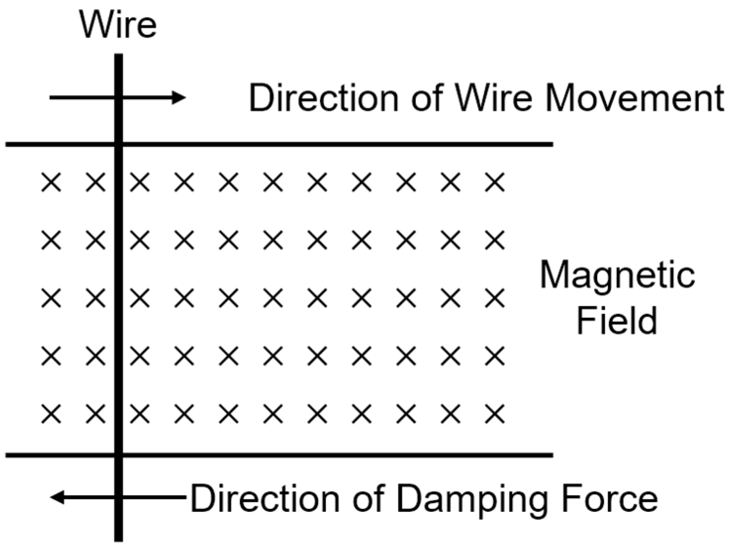
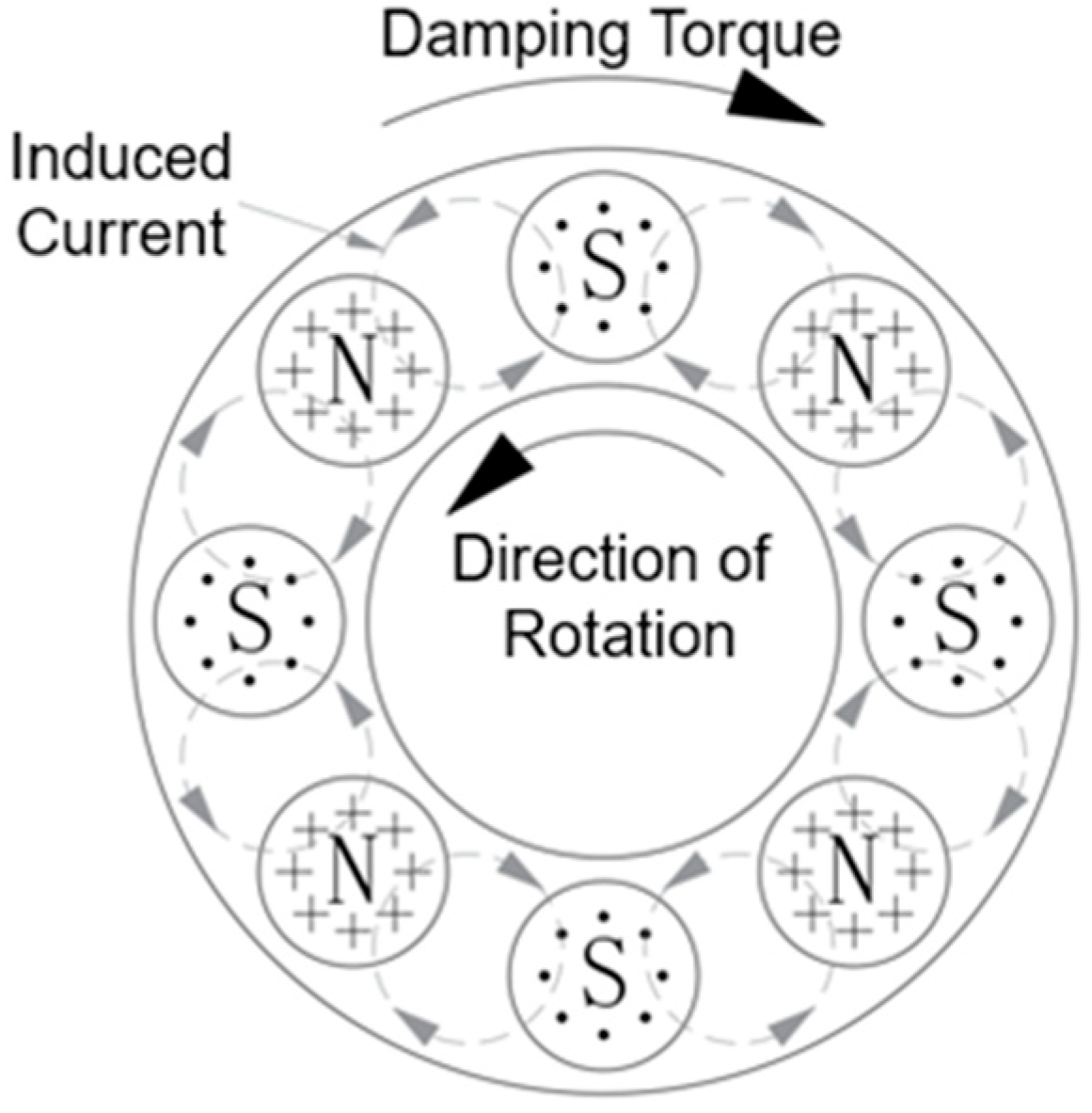
2.1. Operating Principle

From the theorem of electromagnetic induction, it is known that the movement of a wire cutting magnetic induction lines in a magnetic field will produce an induced current, and according to the Lenz’s law, the magnetic field of the induced current will impede the movement of the wire in the magnetic field. In addition, due to the resistance of the wire itself, the induced current flowing through the wire will cause the kinetic energy of the wire to be dissipated as heat energy, thus achieving the effect of impeding the movement [15], as shown in Figure 1.
Electromagnetic dampers are electromagnetic devices based on the abovementioned principles. According to the different excitation methods, electromagnetic dampers can be divided into three types: electrically excited electromagnetic dampers, permanent magnet electromagnetic dampers and hybrid excited electromagnetic dampers [16]. Based to the differences in structure form, electromagnetic dampers can also be divided into rotary electromagnetic dampers, single rotor disk electromagnetic dampers and double rotor disks electromagnetic dampers. Considering the working environment of the nose landing gear and the actual demand of shimmy reduction, the double rotor disks permanent magnet electromagnetic damper is finally selected to eliminate shimmy, and its structure is shown in Figure 2.
The double rotor disks permanent magnet electromagnetic damper mainly includes the stator disk, rotor disks and permanent magnet poles and other components. Six permanent magnets are fixed on each side of the stator disk and they are distributed along the circumference. The two adjacent poles are arranged at intervals of N and S to form three independent groups of poles. The rotor disks are commonly composed of two circular conductor disks on the top and bottom, which will leave a very small air gap when installed with the magnetic poles. This not only ensures that the relative rotation between the upper and lower rotor disks and the stator does not generate friction, but also allows the performance of the electromagnetic damper to be changed by adjusting the size of the air gap [17].
When the electromagnetic damper starts to operate, the magnetic field generated by the magnetic poles forms a circuit between the stator disk, the air gap and the upper and lower rotor disks. The polarity of the two adjacent magnets on each side is opposite, and the magnitude of the magnetic flux is related to the magnetic inductance strength of the magnetic poles. When the rotor disks rotate, the magnetic flux through the rotor disks changes, thus inducing a swirl-shaped induced current on the rotor disks, also known as induced eddy current. As shown in Figure 3, adjacent eddy currents in opposite directions are generated on the rotor disks during operation, and the corresponding induced magnetic field generates a damping torque in the opposite direction of the rotor disks’ rotation, thus impeding the rotation of the rotor disks. From the perspective of energy conversion, the induced currents on the rotor disks transform the kinetic energy of the rotor disks into thermal energy, so as to achieve the effect of shimmy reduction.
Compared with the traditional oleo damper, the electromagnetic damper does not need to consider the need for gas tightness during the assembly process, nor does it need regular inspection of oil quality and quantity during the working process, which greatly reduces the production costs and maintenance costs, reflecting its superiority.

2.2. Analysis of Shimmy Motion Parameters

Combining the engineering practice with the empirical data in the literature [5], the angular amplitude of shimmy is generally around 2 to 20° and the frequency is around 5 to 30 Hz. It shows the characteristics of high frequency at low amplitude and low frequency at high amplitude. Assuming that the nose wheel shimmy amplitude is A (between 2 and 20°) and the frequency is f (between 5 and 30 Hz). The angle of the nose wheel shimmy varies with time in accordance with the sine function relationship:
α = A sin 2 π f t
Then the angular velocity of the nose wheel shimmy is:
ω N W = d α d t = 2 π f A cos 2 π f t
From this, it can be seen that there is a phase difference of 1/4 cycle between the shimmy angle and angular velocity of the nose wheel in line with the above hypothetical law, that is, the angular velocity of the nose wheel is maximum when it passes through the neutral position where the shimmy angle is 0, and the angular velocity is 0 at the position of the maximum shimmy angle (amplitude). The maximum angular velocity is:
ω max = 2 π f A
According to the assumption that 2° shimmy amplitude corresponds to 30 Hz frequency, meawhile, 20° shimmy amplitude corresponds to 5 Hz frequency and the frequency decreases linearly with the increase of shimmy amplitude, the shimmy motion parameters in the above-mentioned range of amplitude and frequency can be deduced as shown in Table 1.

2.3. Damping Requirements for Shimmy Reduction

Combined with the actual needs of the project, the design target of the damping coefficient of shimmy reduction for the research object in this paper is not less than 40 Nms/rad. The output damping coefficient of the electromagnetic damper may be amplified by the transmission mechanism and transmitted to the strut. The amplified damping coefficient should meet the design target under different shimmy motion states described in Table 1. Based on this, the design of the steering structure under the electrically actuated nose wheel steering system and the scheme of the electromagnetic damper are developed in the next sections.

3. Research on Electromagnetic Damping and Shimmy Reduction Scheme of Electrically Actuated Nose Wheel Steering Systems

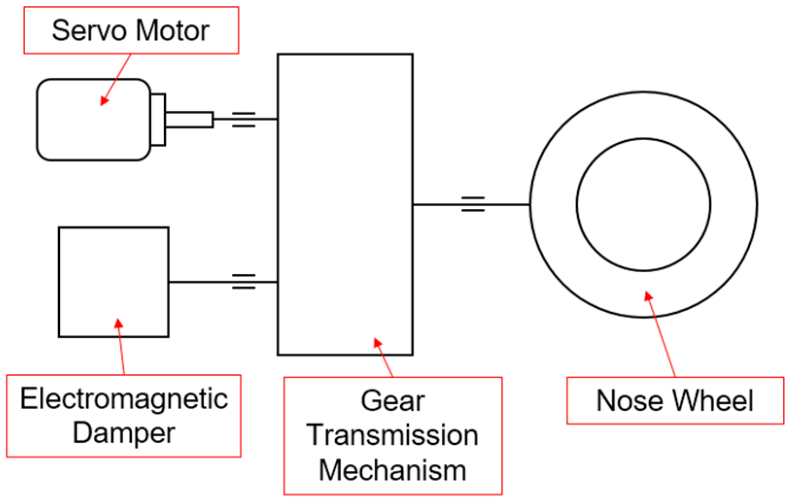
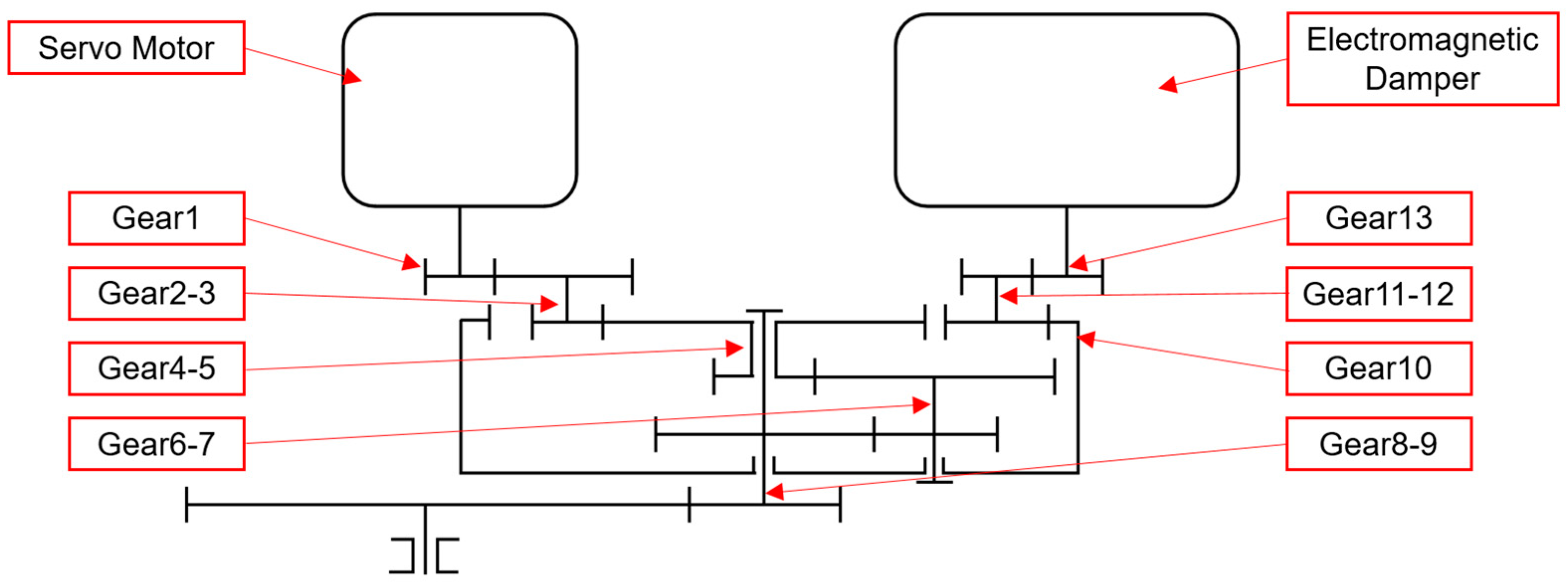
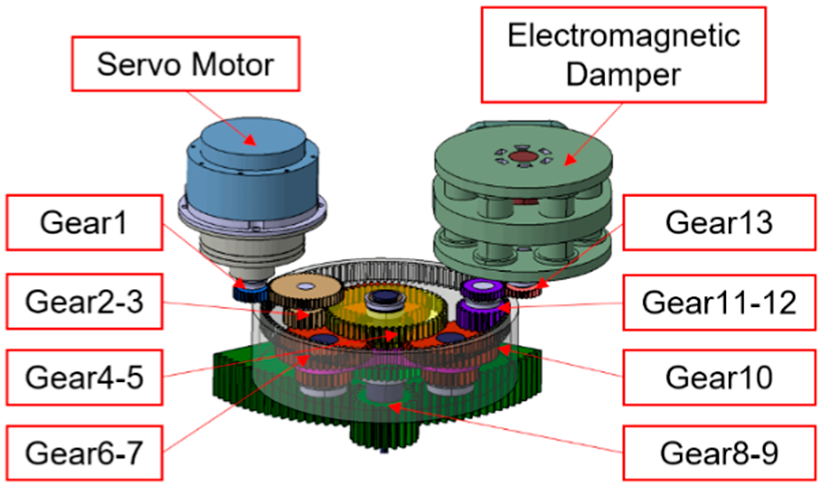
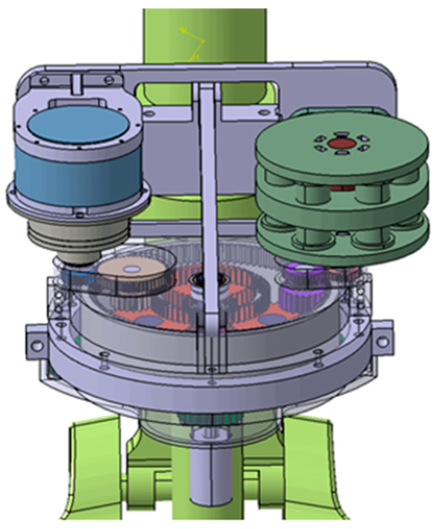
3.1. Structural Scheme Design of the Electrically Actuated Nose Wheel Steering System

The overall design of the structure of the electrically actuated nose wheel steering system uses a gear-driven steering mechanism, and the electromagnetic damper is reasonably installed to better achieve the shimmy reduction function. As shown in Figure 4, the electrically actuated nose wheel steering system includes the transmission mechanism, power output source and other components. The power of the steering mechanism is provided by a servo motor, while the gear transmission mode is selected for the transmission mechanism. Other components include an electromagnetic damper, angle sensors, load sensors, etc.
The schematic diagram of the gear reducer is shown in Figure 5 and the specific structural scheme design is shown in Figure 6. The nose landing gear shimmy reduction channel and the steering channel are connected in parallel in the same gear transmission mechanism. The reducer is a fixed axis gear train during the steering operation of the nose landing gear. Motor shaft gear 1 engages with gear 2, gear 2 is coaxial with 3, gear 3 engages with 4, gear 4 and 5 are duplex gears, gear 6 engages with gear 5, gear 7 is coaxial with 6 and engages with gear 8, gear 8 is coaxial with gear 9, and finally passes to the front landing gear strut gear 12. When the shimmy reduction maneuver is performed, the reducer is a compound gear train, meanwhile, gears 6–7 are planetary gears, and gears 4, 5, 8, 9 are center gears. The motor shaft is braked, the electromagnetic damper gear shaft is the input shaft, gear 13 engages with 12, gear 12 is coaxial with 11, and gear 11 engages with gear 10, driving gears 6–7 to rotate around the center gear and to be able to rotate at the same time, eventually passing to the nose landing gear strut gear 12.
The total transmission ratio of the shimmy reduction channel of the gear reducer is 9.07, and the transmission ratio from the gear reducer to the nose wheel strut is 6, so the total transmission ratio of the shimmy reduction channel is 54.4. A 3D model of the electrically actuated steering shimmy reduction mechanism mounted on the nose landing gear of a jet fighter is shown in Figure 7.

3.2. Mathematical Modeling of the Electromagnetic Damper

3.2.1. Calculation of Eddy Current Skin Depth

When an alternating current, especially a high frequency current, flows through a conductor, it will tend to the conductor surface and flow in a thin layer near the surface, which is the skin effect in electromagnetic field theory [18]. As can be seen from Figure 3, the rotor disks generates eddy currents with alternating directions during rotating around the stator disk.
The analysis of the practical application of electromagnetism shows that the axial distribution of the eddy current density, the electric field strength and the induced magnetic field strength of the alternating eddy current of the electromagnetic damper on the rotor disk decays according to the exponential law e ω μ γ / 2 · h [19], where ω is the angular frequency of the alternating eddy current, μ is the magnetic permeability of the rotor disk material, γ is the electrical conductivity (inverse of the resistivity) of the rotor disk material, and h is the vertical depth from the surface of the rotor disk. In engineering, the depth at which the amplitude of the abovementioned alternating field quantity drops to the surface value of 1/e is generally defined as the penetration depth of skin effect:
  e ω μ γ / 2 · Δ = e 1   Δ = 2 / ω μ γ
As can be seen from the above equation, the higher the angular frequency of the alternating eddy current or the better the conductivity and permeability of the rotor disk material, the shallower the penetration depth of the skin effect.
In addition, let the rotor disk be arranged with n magnets (for an even number to ensure that adjacent poles are reversed), then the fixed position on the rotor disk rotates for one circle and the eddy current direction changes n times, that is, it experiences n/2 complete alternating periods. Let the rotating angular velocity of the rotor disk be ωn, then the rotor disk rotation period and frequency are:
T R o t o r = 2 π ω n
f R o t o r = 1 T R o t o r = ω n 2 π
The eddy current alternating period, frequency and angular frequency at a fixed position on the rotor disk are:
T E c = T R o t o r n / 2 = 4 π n ω n
f E c = 1 T E c = n ω n 4 π
ω = 2 π f E c = n ω n / 2
Therefore, the penetration depth of skin effect can be further expressed as:
Δ = 2 / ω μ γ = 2 / n ω n μ γ

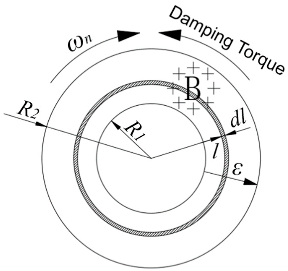
3.2.2. Calculation of Damping Torque

Assuming that the magnetic flux density of a single magnet passing through a rotor disk is B, the rotor disk is regarded as consisting of countless small iron rods centered on the circle and having length R2-R1. When the rotor disk rotates, the small iron rod cuts the magnetic lines of force to excite the electromotive force, thus forming an eddy current on the surface of the rotor disk [20], as shown in Figure 8.
Let the rotor disk rotate with linear velocity V and angular velocity ωn. Then the induced electromotive force generated on the inner and outer sides of the micro-ring with width dl is:
d ε = V × B d l = ω n B l d l
The resistance value of the inner and outer sides of the micro-ring with width dl and the current value flowing along the radial direction through the inner and outer sides of this micro-ring are:
d R = ρ d l 2 π l Δ
I d R = d ε d R = 2 π ω n B l 2 Δ ρ
On the premise of uniform magnetic field, combined with ampere force formula, the damping force and damping torque of the micro-ring under the action of the magnetic pole can be calculated as follows:
d F = B I d R d l = 2 π ω n B 2 l 2 Δ ρ d l
d T = l d F = 2 π ω n B 2 Δ ρ l 3 d l
For the integration of the above-mentioned micro-ring torque in the entire rotor disk (from R1 to R2), the damping torque of a single rotor disk under the action of magnet can be preliminarily calculated, that is:
  T 1 = R 1 R 2 d T = R 1 R 2 2 π ω n B 2 Δ ρ l 3 d l = π R 2 4 R 1 4 ω n B 2 Δ 2 ρ
It should be noted that in the derivation of the above equation, it is assumed that the entire rotor disk is located within the uniform magnetic field. However, the actual area of the magnetic poles acting on the rotor disk is approximately equal to the permanent magnet cross-sectional area (assuming that the air gap spacing is small enough). Therefore, the damping torque generated by a single rotor disk should be the above equation multiplied by the ratio of the real magnetic flux area to the rotor disk area. Setting the radius of the magnet cross section as rMag, the expression of the damping torque of the double rotor disks permanent magnet electromagnetic damper is:
T n = 2 T 1 n π r M a g 2 π R 2 2 R 1 2 = n π r M a g 2 R 2 2 + R 1 2 ω n B 2 Δ ρ
Based on the derivation of the penetration depth Δ of the skin effect in Equation (10), it can be further obtained that:
T n = n π r M a g 2 R 2 2 + R 1 2 ω n B 2 ρ   2 ρ n ω n μ = 2 π r M a g 2 R 2 2 + R 1 2 B 2 n ω n μ ρ  
From the above derivation results, it can be seen that if we want to increase the damping torque, we need to increase the magnetic flux density through the rotor disk or choose rotor disk materials with lower permeability and lower resistivity and larger size permanent magnets, provided that the rotor disk shape size is determined. At the same time, the greater the angular speed of the rotor disk, the larger the output damping torque.In the structural scheme of the electrically actuated nose wheel steering system proposed in Section 3.1, the nose wheel strut is connected to the electromagnetic damper through a transmission device with transmission ratio i = 54.4. The transmission efficiency of commonly used 8-grade cylindrical spur gears is 0.97, i.e., ηGear = 0.97. The transmission efficiency of the bearings is 0.99, i.e., ηBearing = 0.99, so the total transmission efficiency is 0.81, i.e., η = ηGear5 ·ηBearing5 = 0.81. The angular velocity and damping torque of the nose wheel shimmy are related to the angular velocity and damping torque of the electromagnetic damper itself as:
ω n = i ω S t r u t
T S t r u t = i η T n
According to Equation (18), the damping torque of strut shimmy is:
T S t r u c t = i η T n = 2 i 3 2 η π r M a g 2 R 2 2 + R 1 2 B 2 n ω S t r u t μ ρ
The relationship between the nose landing gear damping torque and the design parameters of the electromagnetic damper and the nose wheel shimmy speed is thus established.

3.2.3. Calculation of Damping Coefficient

Whether the nose wheel dampers can meet the damping requirements of aircraft taxiing on the ground is judged mainly by how many damping coefficients they can provide. The damping coefficient of dampers or struts is usually defined in engineering applications by the ratio of damping torque and angular velocity, and then the damping coefficients of the dampers and struts are:
h n = T n ω n = 2 π r M a g 2 R 2 2 + R 1 2 B 2 n μ ρ ω n
h S t r u t = T S t r u t ω S t r u t = i 2 η h n = 2 π i 2 η r M a g 2 R 2 2 + R 1 2 B 2 n μ ρ ω n
From Equations (22) and (23), it can be seen that the damping coefficient decreases if the rotor disk angular velocity increases. The next step is to design the specific scheme of the electromagnetic damper based on the demand of the damping coefficient of the shimmy reduction, the structural scheme of the electrically actuated nose wheel steering system and the derivation of the theoretical calculation.

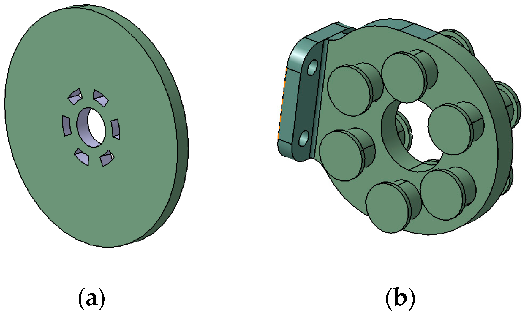
3.3. Design of the Electromagnetic Damper

Based on the operating principle of the electromagnetic damper, the materials selected for each component are shown in Table 2.
The resistivity of steel 1010 is 5 × 10⁻⁷ Ωm and the permeability is 1.8 × 10⁻³ H/m. This scheme uses a permanent magnet with the magnetic flux density of 0.86 T. Assuming that the air gap between the magnetic pole of the permanent magnet and the rotor disk is small enough. In order to meet the target of the damping coefficient of not less than 40 Nms/rad, according to Equations (18) and (21), dimensions of electromagnetic damper components can be obtained which are shown in Table 3.
The damping torque and damping coefficient of the electromagnetic damper and the strut under the shimmy motion distribution for this set of design parameters are shown in Table 4.
From the data in Table 4, it can be seen that the theoretical calculated values of the damping coefficient of the electromagnetic damper amplified to the strut by the transmission mechanism are all satisfactory according to the design index. In the actual installation, there is an air gap between the rotor disk and the magnetic poles, which will cause the magnetic flux density of the poles to be attenuated on the rotor disks. In order to verify the correctness of the mathematical model and theoretical calculations, and to study in depth the shimmy reduction characteristics of the double rotor disks permanent magnet electromagnetic damper applied to the electrically actuated nose wheel steering system, finite element simulation in the electromagnetic field is required.

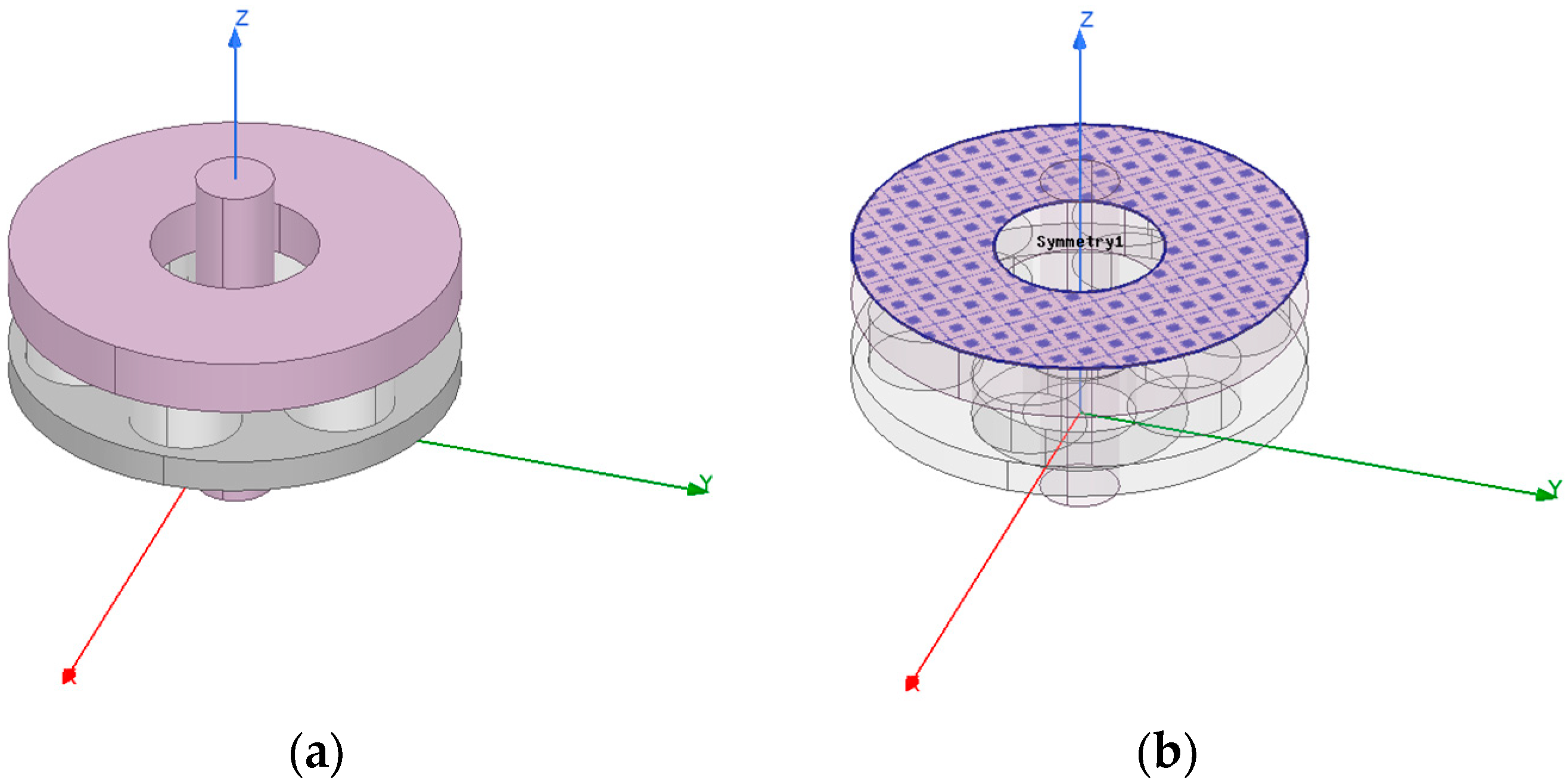
4. Electromagnetic Field Simulation of the Electromagnetic Damper

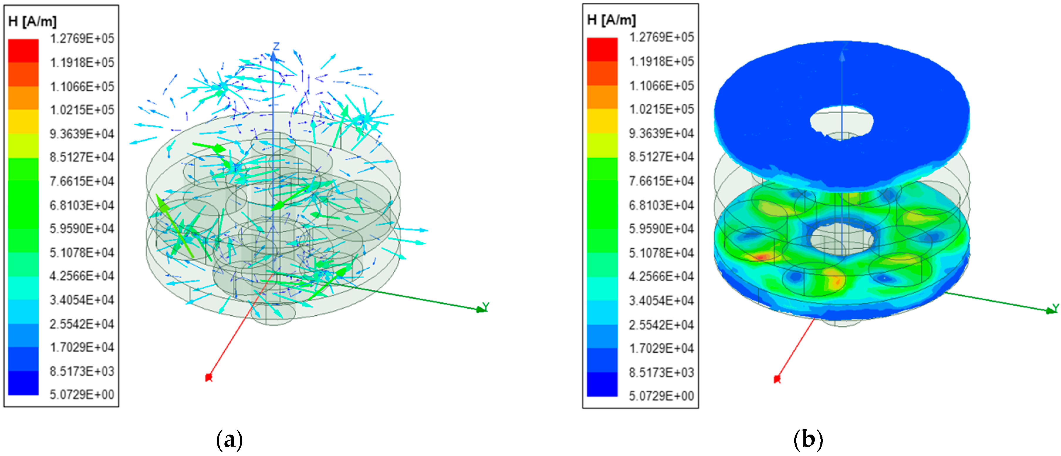
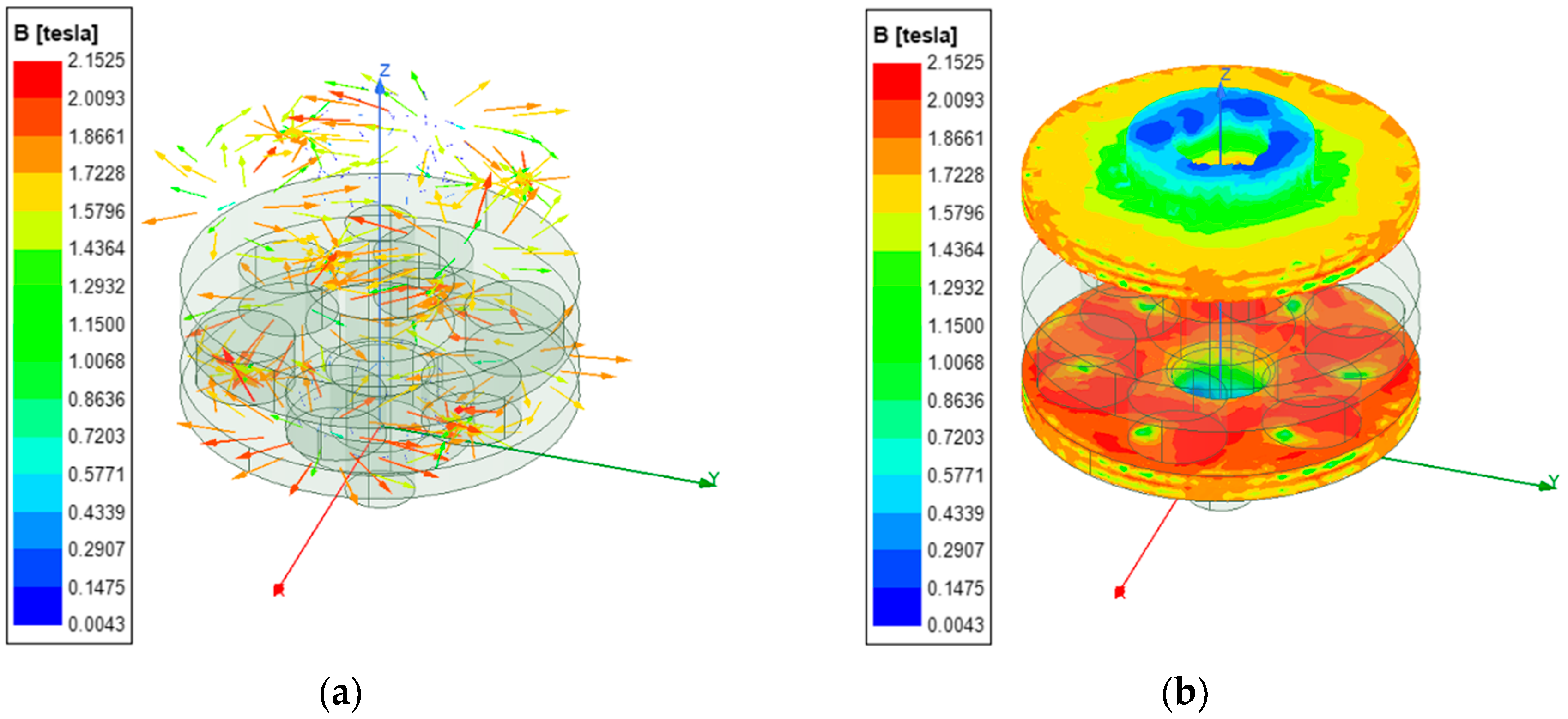
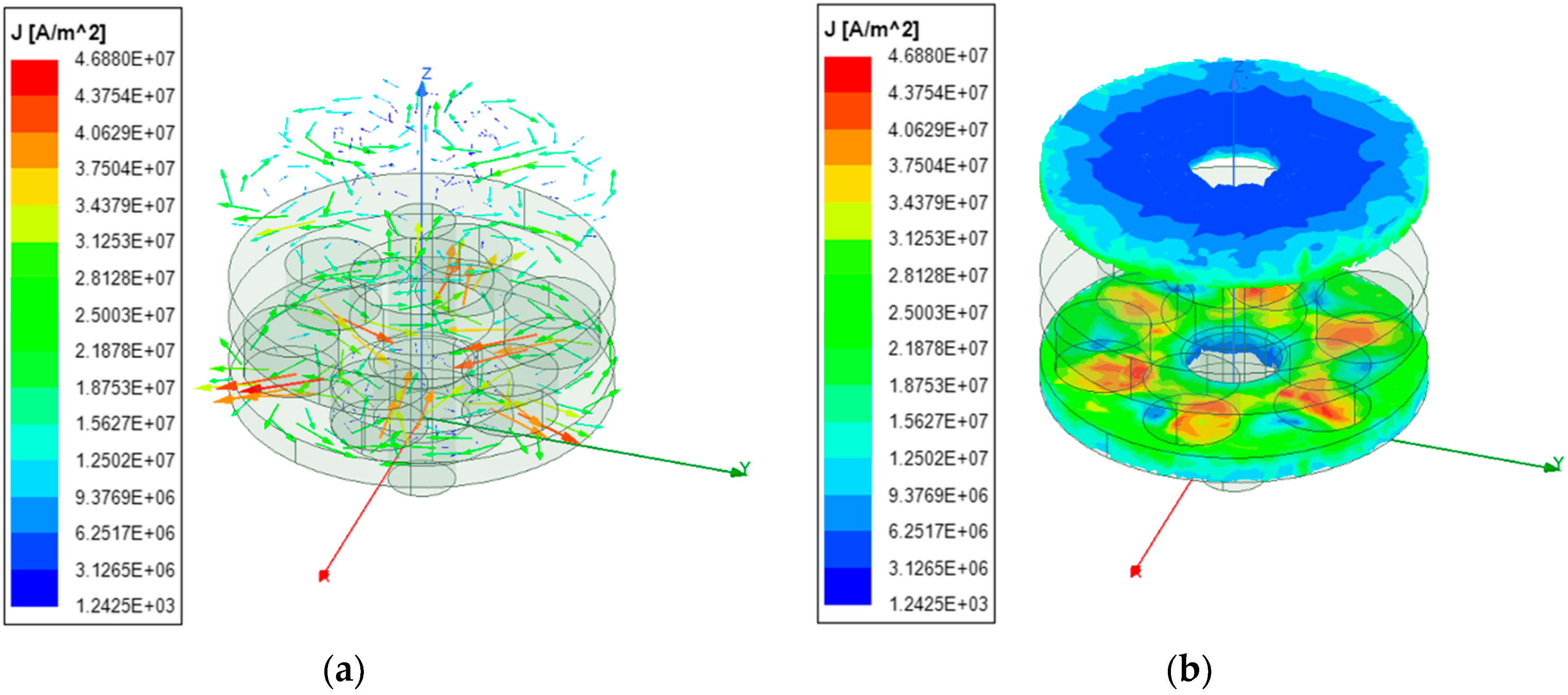
4.1. Static Simulation Results and Analysis of the Electromagnetic Damper

The finite element simulation software generally used for electromagnetic devices such as electromagnetic dampers is Maxwell. Maxwell is an interactive software package that uses finite element analysis (FEA) to solve 3D electrostatic, magnetostatic, eddy current, and transient problems. Using Maxwell we can compute:
  • Static electric fields, forces, torques, and capacitances caused by voltage distributions and charges;
  • Static magnetic fields, forces, torques, and inductances caused by DC currents, static external magnetic fields, and permanent magnets;
  • Time-varying magnetic fields, forces, torques, and impedances caused by AC currents and oscillating external magnetic fields;
  • Transient magnetic fields caused by electrical sources and permanent magnets.
The magnetostatic solver in Maxwell software is selected for the static magnetic field simulation of the electromagnetic damper. In a magnetostatic solution, the magnetic field is produced by DC currents flowing in conductors/coils and by permanent magnets. The electric field is restricted to the objects modeled as real (non-ideal) conductors. The electric field existing inside the conductors as a consequence of the DC current flow is totally decoupled from the magnetic field. Thus, as far as magnetic material properties are concerned, the distribution of the magnetic field is influenced by the spatial distribution of the permeability. There are no time variation effects included in a magnetostatic solution, and objects are considered to be stationary. The energy transformation occurring in connection with a magnetostatic solution is only due to the ohmic losses associated with the currents flowing in real conductors.
The magnetostatic field solution verifies the following two Maxwell’s equations:
× H = J
B = 0
with the following constitutive (material) relationship being also applicable:
B = μ 0 H + M = μ 0 H + μ 0 μ r M p  
where H x , y , z is the magnetic field strength; B x , y , z is the magnetic flux density; J x , y , z is the conduction current density; M p x , y , z is the permanent magnetization; μ 0 = 4 π 10 7   H / m is the permeability of vacuum; μ r is the relative permeability.
The 3D numerical model of the electromagnetic damper is established according to the form dimensions in Table 3. To simplify the calculation, the central cross section of the stator disk is selected as the even symmetry surface, as shown in Figure 9, and the distribution of magnetic flux density on the rotor disk when it is stationary is analyzed.
Firstly, the parameters of relative permeability, conductivity and coercivity of the permanent magnet poles are corrected, and the simulation results of the magnetic flux density of magnetic poles are shown in Figure 10. The magnetic field strength directions of the adjacent magnetic poles are opposite, and the magnetic flux density provided by each pole is calculated between 0.852–0.865 T by the fields calculator, which is basically consistent with the properties of the permanent magnet actually selected for this scheme.
The distribution of magnetic flux density on the rotor disks under the action of magnetic poles close to the real conditions is shown in Figure 11.
It can be seen from the static magnetic flux density distribution on the rotor disks:
(1)
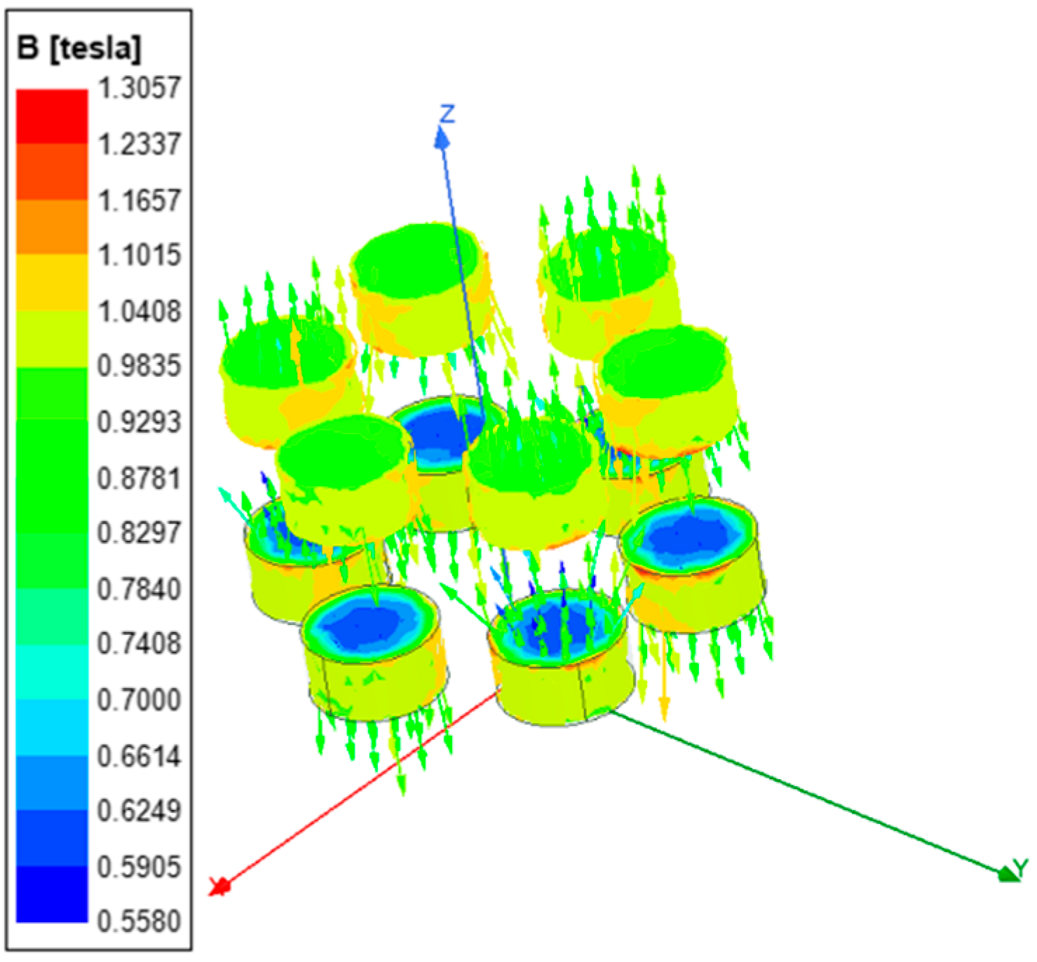
In the two areas of the rotor disk below the adjacent poles, the magnetic flux densities are in opposite directions but they are equal in values.
(2)
The magnetic field superposition at the circumferential edge of the area corresponding to the magnetic poles leads to the maximum magnetic flux density, which can reach 1.26T, and gradually decays in all directions.

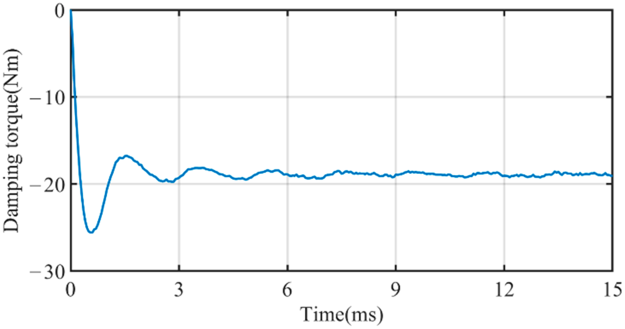
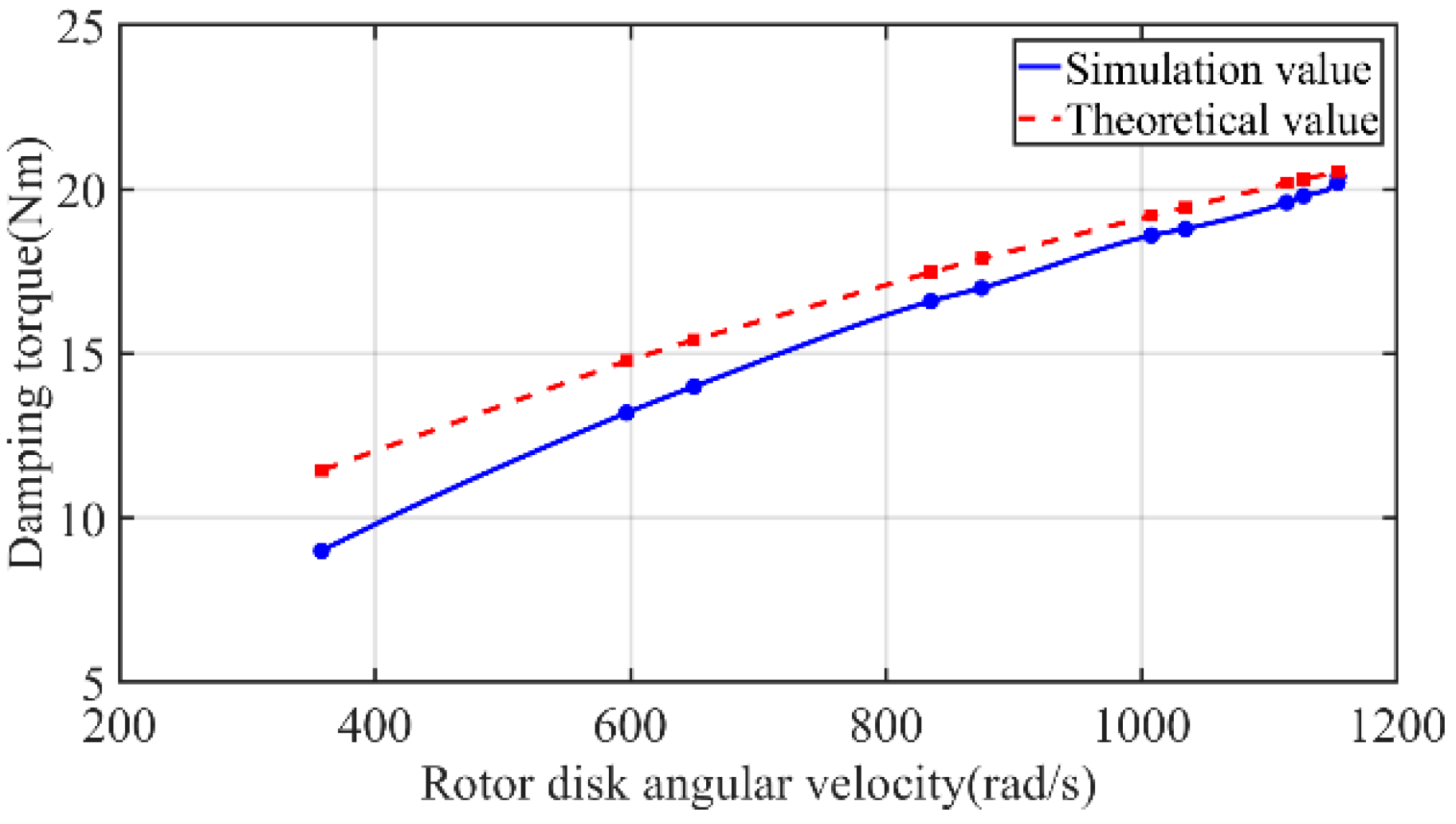
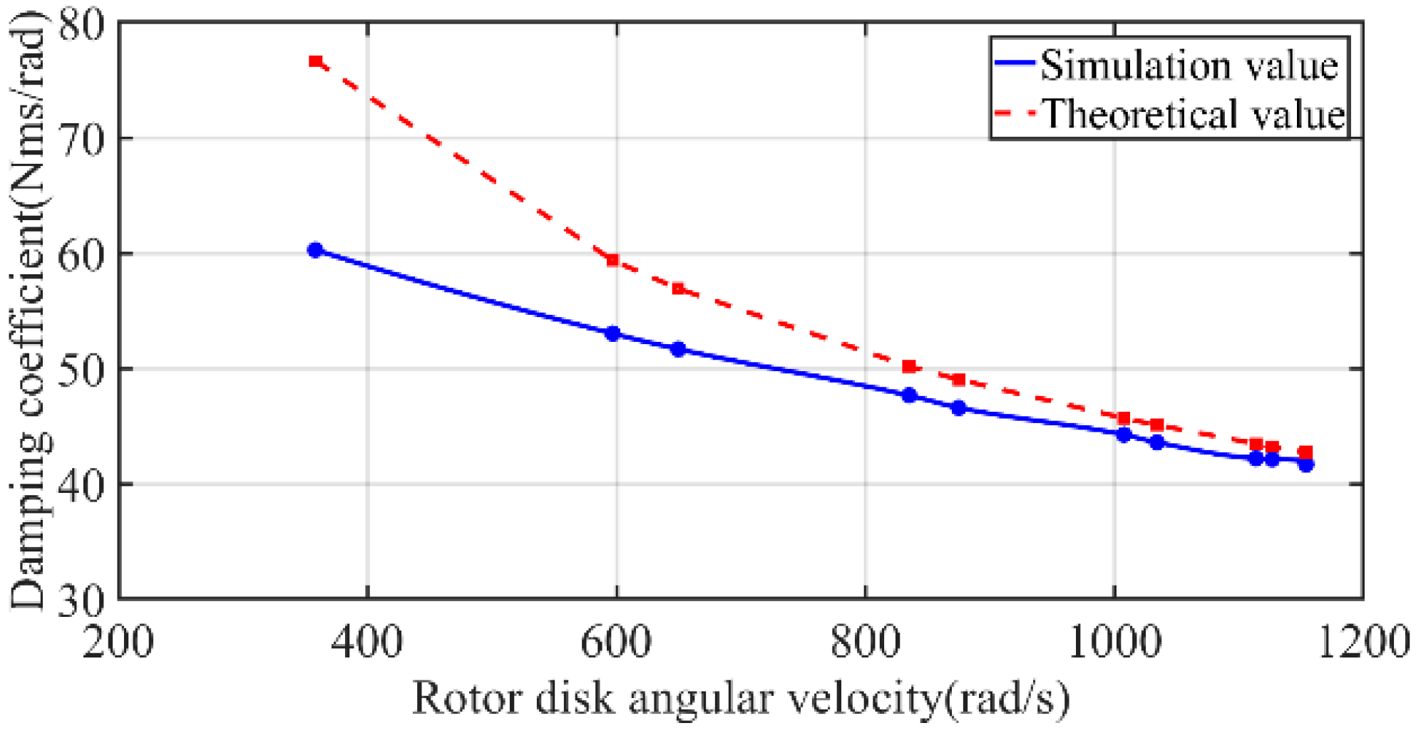
4.2. Dynamic Simulation Results and Analysis of the Electromagnetic Damper

The dynamic simulation of the electromagnetic damper is also completed in Maxwell finite element software, and the difference with the static simulation is that the solver is changed to transient. In the 3D transient (time domain), the solver uses the T Ω formulation. Motion (translational or cylindrical/non-cylindrical rotation) is allowed, excitations-currents and/or voltages-can assume arbitrary shapes as functions of time, nonlinear BH material dependencies are also allowed. For a simpler formulation of problems where motion is involved, Maxwell uses a particular convention and uses the fixed coordinate system for the Maxwell’s equations in the moving and the stationary part of the model. Thus the motion term is completely eliminated for the translational type of motion while for the rotational type of motion a simpler formulation is obtained by using a cylindrical coordinate system with the z axis aligned with the actual rotation axis.
The formulation used by the Maxwell transient module supports Master-Slave boundary conditions and motion induced eddy currents everywhere in the model, in the stationary as well as in the moving parts of the model. Mechanical equations attached to the rigid-body moving parts allows a complex formulation with the electric circuits being strongly coupled with the finite element part and also coupled with the mechanical elements whenever transient mechanical effects are included by users in the solution. In this case the electromagnetic force/torque is calculated using the virtual work approach. For problems involving rotational type of motion a “sliding band” type of approach is followed and thus no re-meshing is done during the simulation.
The following two Maxwell’s equations are relevant for transient (low frequency) applications:
× H = σ E
× E = B t
The following equation directly results from the above two equations:
× 1 σ × H + B t = 0
The final result is a formulation where vector fields are represented by first order edge elements and scalar fields are represented by second order nodal unknowns.
The rotor disks’ output damping torque is taken as the target parameter for the study. Because there are many operating conditions involved in the distribution of the shimmy motion, the set of motion parameters ωn = 1034.14 rad/s in Table 4 is used as an example to analyze the dynamic magnetic field simulation results of the electromagnetic damper. The output damping torque of the double rotor disks under this operating condition is shown in Figure 12.
As can be seen from Figure 12, when the rotor disks start to move suddenly in the magnetic field generated by the poles of the permanent magnet, vibration is generated and the value of the output damping torque temporarily fluctuates. After 6 ms, the motion of the rotor disk stabilizes and the output damping torque remains constant around 18.8 Nm, which is close to the theoretical calculated value of the mathematical model under this condition with small deviation. It also shows that in engineering practice, electromagnetic dampers can quickly respond to and suppress the instantaneous shimmy of nose wheels, which demonstrates its superiority compared with traditional oleo dampers.
The following is an in-depth analysis of the simulation results of the rotor disks magnetic field strength distribution, magnetic flux density and current density during stable operation.
As shown in Figure 13, the magnetic field strength on the surface of the rotor disks during the stable operation of the electromagnetic damper is in the range of 8517–127690 A/m. The magnetic field strength distribution is more concentrated in the area close to the permanent magnets, and the magnetic poles of the two adjacent concentrated areas are opposite.
As shown in Figure 14, the distribution of magnetic flux density on the rotor disks is also concentrated in the area close to the permanent magnets. When the electromagnetic damper is operating, the induced magnetic field on the rotor disks will be generated, and after superimposing the magnetic field of the permanent magnet poles through the rotor disks, the magnetic flux density is about 0.86–2.15 T, which is significantly larger than the static magnetic flux density of the permanent magnet pole in Figure 10.
As shown in Figure 15, the induced eddy current density of the rotor disks is in the range of 1.25 × 10⁷–4.69 × 10⁷ A/m2. Observing the vector distribution, it can be found that the adjacent eddy currents on the surface of the rotor disks are in opposite directions, which proves the correctness of the electromagnetic damper using the induced eddy currents to convert kinetic energy into thermal energy. Meanwhile, observing the field distribution, it can be found that the induced eddy currents on the rotor disks are mainly concentrated on the surface near the pole side, which also proves the existence of skin effect and is consistent with the mathematical model.
The above simulation results are based on the set of motion parameters ωn = 1034.14 rad/s. In order to study the shimmy reduction performance of the electromagnetic damper in the electrically actuated nose wheel steering system, all shimmy motion states listed in Table 4 need to be considered, and the output damping torque of the electromagnetic damper corresponding to each operating condition is shown in Figure 16.
By comparing the simulation curve and the theoretical calculation curve of the output damping torques of the electromagnetic damper under various operating conditions, it can be found that the simulation value and the theoretical value are closer, which shows that:
(1)
The mathematical model of the electromagnetic damper is reasonable;
(2)
The application of electromagnetic dampers to the shimmy reduction function of electrically actuated nose wheel steering systems is also feasible, but there are some differences in the values at some data points and the slopes of the two curves are not identical, because:
  • When calculating the output damping torques of the electromagnetic damper using Equation (18), the magnetic flux density of the permanent magnet source is assumed to be the magnetic flux density on the surface of the rotor disks, and the magnetic losses caused by the air gap and resistance and the induced magnetic field generated by the rotor disks themselves during rotation are ignored;
  • The magnetic permeability of the permanent magnet material is simply taken as a constant value in the numerical calculation. However, from the hysteresis curve of the permanent magnet material in the finite element simulation, the magnetic field strength is not linearly related to the magnetic flux density, and the relative permeability is also not linear;
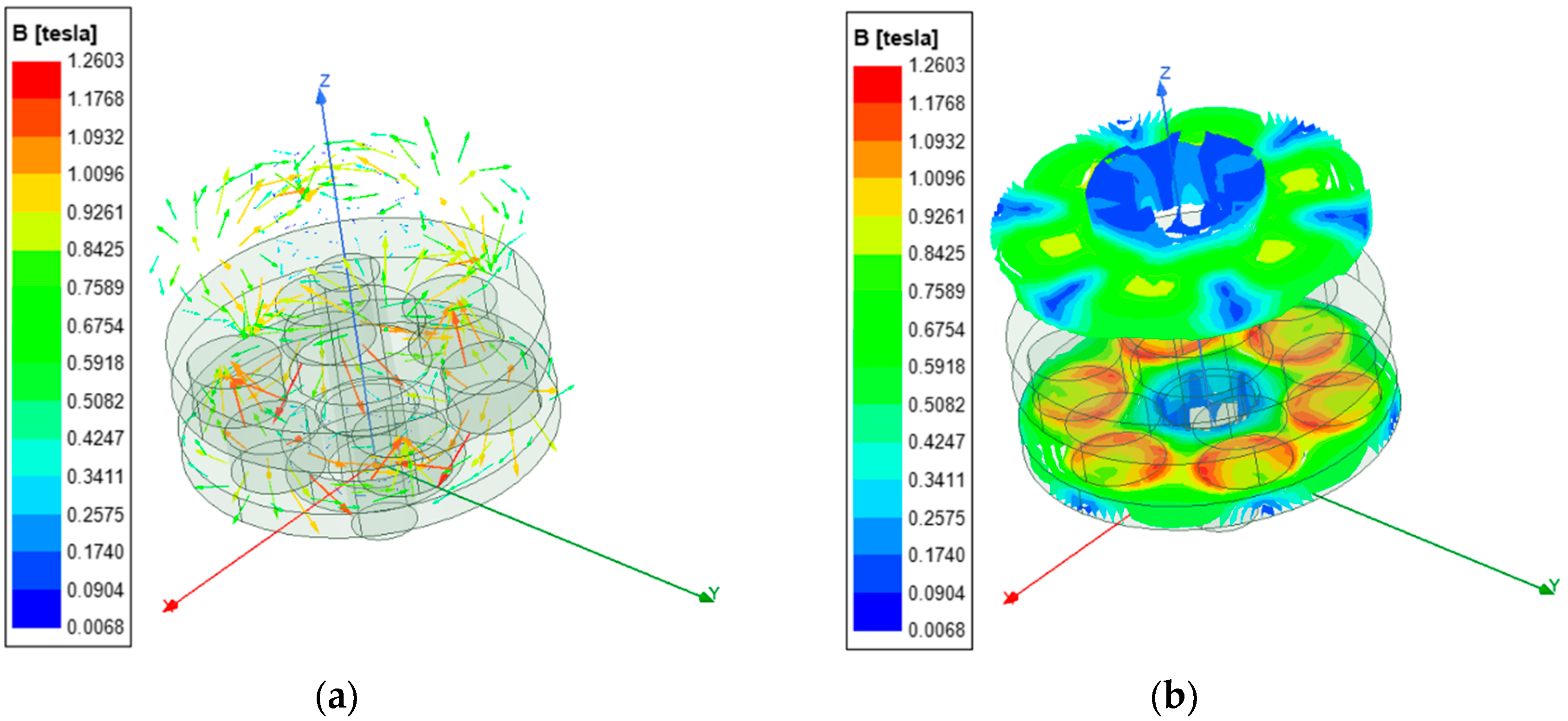
  • The demagnetization effect of the permanent magnet is not taken into account in the whole mathematical modeling process of the electromagnetic damper, while the experimental results in the literature [21] show that the demagnetization effect is actually real. The magnetic flux density distribution of the permanent magnet magnetic pole at the relative angular velocity of 1034.14 rad/s is shown in Figure 17, and comparing the static magnetic flux density distribution of the pole in Figure 10, it can be found that the finite element simulation takes this demagnetization effect into account;
By observing Figure 16, it can be found that when the rotor disk rotates at a low speed, the theoretical value of its output damping torque is greater than the simulation value, because in the process of theoretical derivation, the mechanical power of the rotor disk is considered to be fully converted into electromagnetic power, while the electromagnetic loss is ignored. In addition, the offsetting effect of opposite poles when multiple permanent magnets work simultaneously is not taken into account in the theoretical derivation. When the rotor disk rotates at high speed, the simulation value of the output damping torque is closer to the theoretical value because the induced magnetic field superimposed on the surface of the rotor disk is large enough, which can not only ignore the demagnetization effect of the magnetic poles at high speed, but also make up for the power loss in the theoretical calculation.
We can draw the curves between the damping coefficient of the electromagnetic damper amplified by the transmission mechanism and its own angular velocity, as shown in Figure 18.
It can be seen from Figure 18 that the damping coefficient of shimmy reduction provided by the electromagnetic damper varies with the shimmy frequency when the transmission mode is determined. Figure 16 and Figure 18 show that the damping torque increases while the damping coefficient decreases as the angular velocity of the rotor disk increases, which is consistent with the derivation of Equations (18) and (23). Therefore, when evaluating the damping performance of electromagnetic dampers, we should pay more attention to the damping coefficient under high frequency shimmy.

4.3. Effect of Various Factors on the Performance of Electromagnetic Dampers

According to the operating principle and magnetic field simulation of electromagnetic dampers, there are many factors that affect the performance of electromagnetic dampers to reduce shimmy, here the two key factors, the dimensions R2 and R1 of the rotor disks and air gap width δ, are studied in detail, the former has direct reference value for the structural design of electromagnetic dampers under the premise of known shimmy reduction index requirements, the latter is the most important way to adjust the output damping torque after the structural scheme of the electromagnetic damper is determined.
As discussed in Section 4.2, because there are more operating conditions involved in the shimmy motion distribution, and the shimmy reduction design index usually requires the minimum shimmy reduction damping coefficient of the damper, the set of motion parameters ωn = 1153.82 rad/s in Table 4 is used as an example to analyze the influence of the rotor disks’ outer diameter R2 and air gap width δ on the shimmy reduction performance of the electromagnetic damper, respectively.

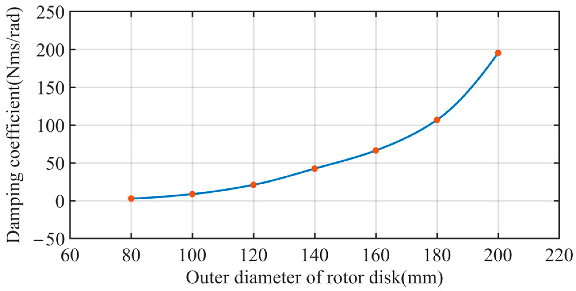
4.3.1. Study of the Effect of Rotor Disks’ Dimensions R2 and R1 on Electromagnetic Damping

The rotor disks with R2 = 80 mm and R1 = 20 mm are used as the starting point and scaled by 1.25, 1.5, 1.75, 2, 2.25 and 2.5, respectively. The results of the damping coefficients after being enlarged by the transmission mechanism are shown in Figure 19. The outer dimensions of the rotor disks enlarged by 1.75 are the rotor disks’ outer diameter R2 = 140 mm and the inner diameter R1 = 35 mm selected for this scheme.
From Figure 18, it can be seen that by changing the dimensions of the electromagnetic damper, the damping coefficient amplified by the transmission mechanism ranges from 2.83 to 195.29 Nms/rad, and there is an approximate quadratic power relationship with the dimensions of the rotor disks of the electromagnetic damper, which once again verifies the correctness of the derivation of the damping coefficient in the mathematical model.

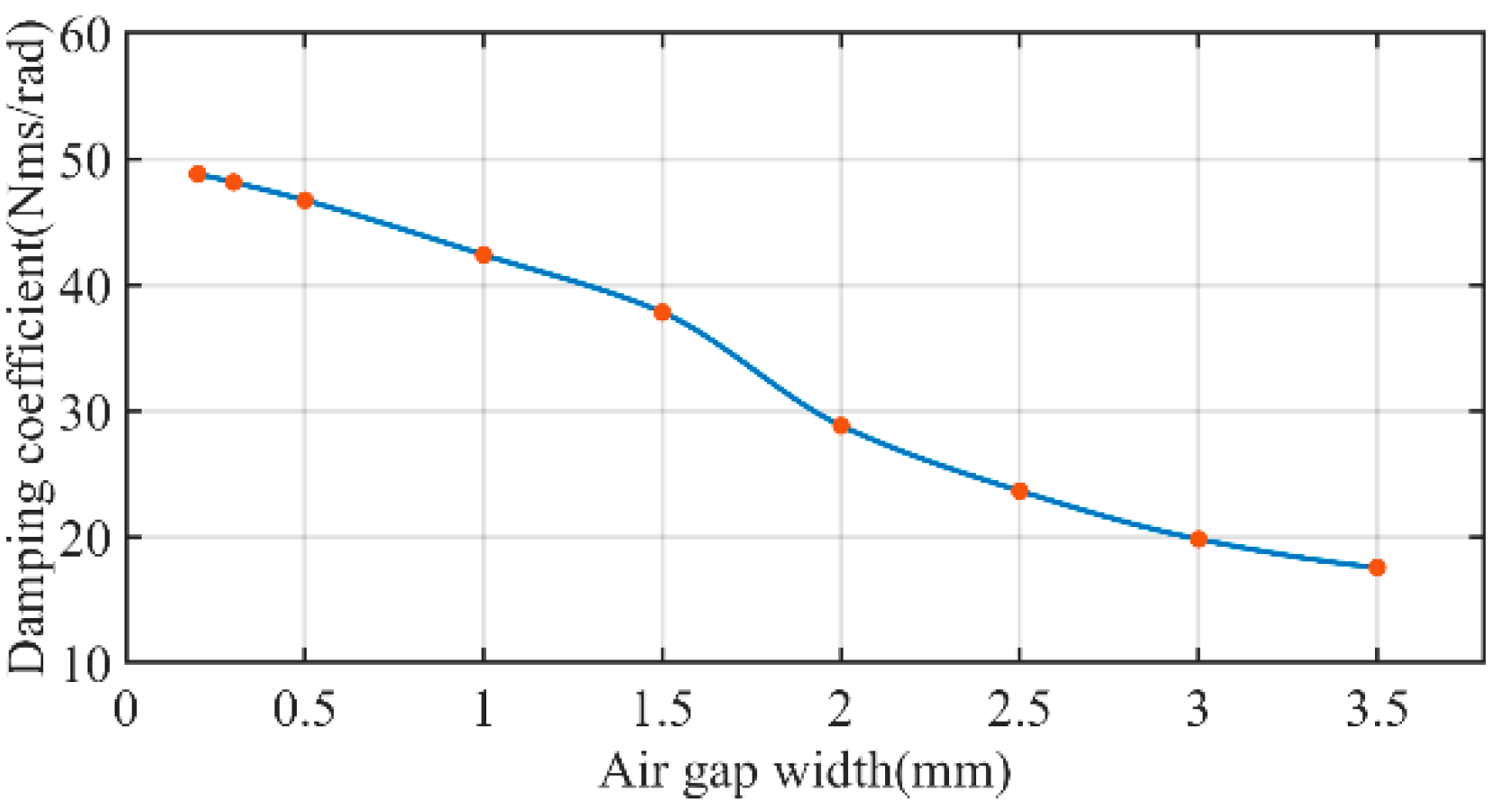
4.3.2. Study of the Effect of Air Gap Width δ on Electromagnetic Damping

The width of the air gap between the rotor disks and the permanent magnet poles is generally obtained within the range of 0.5–3 mm. Too small will lead to the thermal expansion and collision of the rotor disks and the permanent magnet poles during operating, while too large will lead to a sharp decline in the performance of the electromagnetic damper shimmy reduction. Since the air gap is composed of air, whose relative permeability is 1, and other parts such as the rotor disks and the stator disk are composed of high permeability materials, so the magnetic resistance of other structures can be neglected relative to the air gap. Taking the air gap width δ as 0.2, 0.3, 0.5, 1, 1.5, 2, 2.5, 3 and 3.5 mm, respectively, the corresponding output torque of the electromagnetic damper is obtained as shown in Figure 20.
For permanent magnet electromagnetic dampers, the magnetoresistance increases as the air gap width increases, while the flux is the ratio of the magneto motive force to the magnetoresistance. The flux decreases with increasing magnetoresistance and constant magneto motive force, producing a flux density in the magnetic saturation region, which decreases more slowly, and then in the non-saturation region, which decreases rapidly. From Figure 20, it can be seen that during the reduction of the air gap width from 3.5 mm to 0.2 mm, the damping coefficient of shimmy reduction gradually increases from 17.55 Nms/rad to 49.79 Nms/rad, while the change of the damping torque of shimmy reduction slows down during the continued reduction from 1.5 mm, indicating that the induced magnetic field on the rotor disks has started to enter the saturation state. Therefore, within a certain range, the magnetic flux density can be increased by reducing the air gap to increase the output damping torque of the electromagnetic damper, but the air gap should not be too small considering the influence of mechanical processing precision and material thermal expansion and contraction.

5. Conclusions

In this paper, an electromagnetic damping method for an electrically actuated nose wheel steering system is studied, a structural scheme of the electrically actuated nose wheel steering system is proposed, and a new electromagnetic damping shimmy reduction device integrated in this system is designed. In order to verify the shimmy reduction performance of the proposed electromagnetic damper, the corresponding mathematical model of the electromagnetic damper is established, and then the specific scheme design of the electromagnetic damper is carried out and parametric modeling and electromagnetic field simulation are conducted according to the design index of shimmy reduction damping coefficient, and the following conclusions are obtained:
(1)
After correcting the assumption that the rotor disk is located in the uniform magnetic field, which was commonly used in the previous derivation process, and combining the calculation of the skin depth, the derived equation for the output damping torque of the electromagnetic damper is closer to the simulated value;
(2)
The electromagnetic damper designed in this paper can provide a damping coefficient of not less than 40 Nms/rad under the conditions of shimmy amplitude between 2–20° and frequency between 5–30 Hz, which not only meets the requirements of the index, but also overcomes the disadvantages of relying on the hydraulic power source compared with the traditional oleo dampers. It also has the advantages of higher reliability, lower maintenance cost and faster response;
(3)
There is an approximate quadratic relationship between the dimensions R2 and R1 of the rotor disks and the damping coefficient. The preliminary structural design of electromagnetic dampers’ dimensions can be based on this relationship when the shimmy reduction index requirements are given;
(4)
The air gap width δ of the electromagnetic damper designed in this paper can be adjusted to obtain a range of 17.55–49.79 Nms/rad for the damping coefficient. In the actual engineering application, the required damping coefficient can be obtained by adjusting the air gap width δ of the electromagnetic damper for different shimmy conditions.
(5)
The application of electromagnetic damping technology to strut damping is the first comprehensive and systematic study of this technology at the theoretical and simulation levels, which can be applied not only to the design of electrically actuated nose wheel steering systems for various types of aircraft, but also to other impact cushioning and vibration energy recovery fields.

Author Contributions

Conceptualization: C.S. and M.Z.; Investigation: M.Z., Y.G., H.Y. and G.P.; Methodology: C.S., M.Z. and Y.G.; Project administration: M.Z.; Software: C.S. and L.T.; Supervision: M.Z. and Y.G.; Visualization: C.S., H.Y. and G.P.; Writing—original draft: C.S. and L.T.; Writing—review & editing, M.Z. All authors have read and agreed to the published version of the manuscript.

Funding

This research was funded by the Aeronautical Science Foundation of China under Grant No. 20182852021.

Institutional Review Board Statement

Not applicable.

Informed Consent Statement

Not applicable.

Data Availability Statement

Not applicable.

Acknowledgments

The author would like to thank the reviewers and the editors for their valuable comments and constructive suggestions that helped to improve the paper significantly.

Conflicts of Interest

The authors declare no conflict of interest.

Nomenclature

The following nomenclatures are used in this manuscript:
ANose wheel shimmy amplitude
fNose wheel shimmy frequency
αNose wheel shimmy angle
ωNWAngular velocity of nose wheel shimmy
ωmaxMax angular velocity of the nose wheel shimmy
ωAngular frequency of the eddy current
μMagnetic permeability of the rotor disk material
γElectrical conductivity of the rotor disk material
hVertical depth from the surface of the rotor disk
Δ Penetration depth of skin effect
ωnRotation angular velocity of the rotor disk
TRotorRotation period of the rotor disk
fRotorRotation frequency of the rotor disk
TEcAlternating period of the eddy current
fEcFrequency of the eddy current
BMagnetic flux density of a single magnet passing through a rotor disk
VRotation linear velocity of the rotor disk
Induced electromotive force of the micro-ring
dlWidth of the micro-ring
dRResistance of the micro-ring
IdRCurrent value flowing along the radial direction of the micro-ring
ρResistivity of the rotor disk material
dFDamping force of the micro-ring
dTDamping torque of the micro-ring
R2Outer radius of the rotor disk
R1Inner radius of the rotor disk
T1Damping torque of a single rotor disk
rMagRadius of the magnet cross section
TnDamping torque of the electromagnetic damper
iTransmission ratio
ηGearTransmission efficiency of the 8-grade cylindrical spur gear
ηBearingTransmission efficiency of the bearing
ηTotal transmission efficiency
ωStrutAngular velocity of the nose landing gear strut
TStrutDamping torque of the nose landing gear strut
hnDamping coefficient of the electromagnetic damper
hStrutDamping coefficient of the nose landing gear strut
H Magnetic field strength
B Magnetic flux density
J Conduction current density
M p Permanent magnetization
μ0Permeability of vacuum
μrRelative permeability

References

  1. Cláudio, A.L.; James, C.; Kamran, E.S. Rotor Position Synchronization in Central-Converter Multi-Motor Electric Actuation Systems. Energies 2021, 14, 7485. [Google Scholar] [CrossRef]
  2. George, I.; Stephane, D. Dress: Distributed and Redundant Electro-Mechanical Nose Wheel Steering System. Sae Int. J. Aerosp. 2009, 2, 46–53. [Google Scholar]
  3. Bennett, C.; William, J. Fault Tolerant Electromechanical Actuators for Aircraft. Ph.D. Thesis, Newcastle University, Newcastle, UK, 2010. [Google Scholar]
  4. Liao, P.; Zhang, X.; Li, W. Design of Electrical Swerve Control System for Small Aircraft Undercarriages. Small Spec. Electr. Mach. 2010, 38, 4. [Google Scholar]
  5. Feng, F.; Nie, H.; Zhang, M.; Peng, Y. Effect of Torsional Damping on Aircraft Nose Landing-Gear Shimmy. J. Aircr. 2014, 52, 561–568. [Google Scholar] [CrossRef]
  6. Zhu, P. Shimmy Theory and Anti-Shimmy Measures, 1st ed.; National Defense Industry Press: Beijing, China, 1984; pp. 9–23. [Google Scholar]
  7. Luong, Q.-V.; Jo, B.-H.; Hwang, J.-H.; Jang, D.-S. A Supervised Neural Network Control for Magnetorheological Damper in an Aircraft Landing Gear. Appl. Sci. 2022, 12, 400. [Google Scholar] [CrossRef]
  8. Jo, B.-H.; Jang, D.-S.; Hwang, J.-H.; Choi, Y.-H. Experimental Validation for the Performance of MR Damper Aircraft Landing Gear. Aerospace 2021, 8, 272. [Google Scholar] [CrossRef]
  9. Chen, D.; Gu, H.; Wu, D. Semi-active Control of Landing Gear Shimmy Based on Magneto-rheological (MR) Damper. China Mech. Eng. 2010, 21, 1401–1405. [Google Scholar]
  10. Zhu, S.; Wang, G. Design and Experimental Research of External Coil Type Magnetorheological Shimmy Damper. Mach. Tool Hydraul. 2019, 47, 12–17. [Google Scholar]
  11. Jia, C.; Xia, Y.; Chu, M.; Zhang, X. Post-capture Angular Momentum Management of Space Robot with Controllable Damping Joints. In Proceedings of the 2019 IEEE 2nd International Conference on Automation, Electronics and Electrical Engineering (AUTEEE), Shenyang, China, 22–24 November 2019; pp. 638–642. [Google Scholar]
  12. Kou, B.; Li, L.; Jin, Y.; Pan, D. System for Testing Linear Motor Characteristics. CN Patent 102096042B, 13 February 2013. [Google Scholar]
  13. Ebrahimi, B. Development of Hybrid Electromagnetic Dampers for Vehicle Suspension Systems. Ph.D. Thesis, University of Waterloo, Waterloo, ON, Canada, 2009. [Google Scholar]
  14. Liu, C.; Jiang, K.; Zhang, Y. Design and Use of an Eddy Current Retarder in an Automobile. Int. J. Automot. Technol. 2011, 12, 611–616. [Google Scholar] [CrossRef]
  15. Heald, D.; Mark, A. Magnetic Braking: Improved Theory. Am. J. Phys. 1988, 56, 521–522. [Google Scholar] [CrossRef]
  16. Kou, B.; Jin, Y.; Zhang, H.; Zhang, L.; Zhang, H. Development and Application Prospects of the Electromagnetic Damper. Proc. Chin. Soc. Electr. Eng. 2015, 35, 3132–3143. [Google Scholar]
  17. Gay, S.E.; Ehsani, M. Parametric Analysis of Eddy-Current Brake Performance by 3-D Finite-Element Analysis. IEEE Trans. Magn. 2006, 42, 319–328. [Google Scholar] [CrossRef]
  18. Fujita, T.; Kitade, K.; Yokoyama, T. Development of Original End Point Detection System Utilizing Eddy Current Variation Due to Skin Effect in Chemical Mechanical Polishing. Jpn. J. Appl. Phys. 2011, 50, 05–09. [Google Scholar] [CrossRef]
  19. Jow, H.-M.; Ghovanloo, M. Design and Optimization of Printed Spiral Coils for Efficient Transcutaneous Inductive Power Transmission. IEEE Trans. Biomed. Circuits Syst. 2007, 1, 193. [Google Scholar] [CrossRef] [PubMed]
  20. He, R.; Yi, F.; He, J. A Computation Method for Braking Torque of Eddy Current R19etarder. Automot. Eng. 2004, 26, 197–200. [Google Scholar]
  21. Baranski, M.; Szelag, W.; Lyskawinski, W. Experimental and simulation studies of partial demagnetization process of permanent magnets in electric motors. IEEE Trans. Energy Convers. 2021, 99, 1. [Google Scholar] [CrossRef]
Figure 1. Basic operating principle of an electromagnetic damper.
Aerospace 09 00113 g001
Figure 2. Structural diagram of the electromagnetic damper: (a) Rotor disk; (b) Stator disk.
Aerospace 09 00113 g002
Figure 3. The damping torque and induced current of electromagnetic damper.
Aerospace 09 00113 g003
Figure 4. The design of transmission mechanism.
Aerospace 09 00113 g004
Figure 5. Schematic diagram of the gear reducer.
Aerospace 09 00113 g005
Figure 6. Specific structure of electric nose wheel steering system.
Aerospace 09 00113 g006
Figure 7. 3D model of the electro-mechanical nose wheel steering system.
Aerospace 09 00113 g007
Figure 8. Analysis of the rotor disk potential and damping torque.
Aerospace 09 00113 g008
Figure 9. Finite element simulation model of the electromagnetic damper: (a) Simplified model; (b) Central cross section of the stator disk.
Aerospace 09 00113 g009
Figure 10. Magnetic flux density distribution of permanent magnet poles(static).
Aerospace 09 00113 g010
Figure 11. Static magnetic flux density distribution of the rotor disks: (a) Vector distribution; (b) Field distribution.
Aerospace 09 00113 g011
Figure 12. Output damping torque of the electromagnetic damper.
Aerospace 09 00113 g012
Figure 13. Transient magnetic field strength distribution of the rotor disks: (a) Vector distribution; (b) Field distribution.
Aerospace 09 00113 g013
Figure 14. Transient magnetic flux density distribution of the rotor disks: (a) Vector distribution; (b) Field distribution.
Aerospace 09 00113 g014
Figure 15. Transient eddy current density distribution of the rotor disks: (a) Vector distribution; (b) Field distribution.
Aerospace 09 00113 g015
Figure 16. Distribution of damping torque with angular velocity of the rotor disks.
Aerospace 09 00113 g016
Figure 17. Magnetic flux density distribution of permanent magnet poles (at 1034.14 rad/s).
Aerospace 09 00113 g017
Figure 18. Distribution of damping coefficient with angular velocity of rotor disk.
Aerospace 09 00113 g018
Figure 19. Distribution of damping coefficient with the outer diameter of rotor disk.
Aerospace 09 00113 g019
Figure 20. Distribution of damping torque with the air gap width of the rotor disks.
Aerospace 09 00113 g020
Table 1. Motion parameters of shimmy.
A (°)F (Hz)Angular Velocity of Strut (rad/s)
2.030.006.58
4.027.2211.94
6.024.4416.08
8.021.6719.01
10.018.8920.71
11.816.3921.21
12.016.1121.20
14.013.3320.47
16.010.5618.52
18.07.7815.35
20.05.0010.97
Table 2. Material selection of electromagnetic damper components.
ComponentMaterial
Permanent magnetNdFe35
Stator diskSteel stainless
Rotor diskSteel 1010
Table 3. Dimensions of electromagnetic damper components.
ComponentDiameter (mm)Height (mm)
Outer DiameterInner Diameter
Permanent magnet3518
Stator disk1405218
Rotor disk1403510
Table 4. Distribution of damping torque and damping coefficient with different shimmy state.
ωn (rad/s)ωStrut (rad/s)Tn (Nm)TStrut (Nm)hStrut (Nms/rad)
357.956.5811.45504.3476.65
649.5411.9415.42679.3956.90
874.7516.0817.89788.4149.03
1034.1419.0119.45857.2545.09
1126.6220.7120.31894.7643.20
1153.8221.2120.55905.4942.69
1153.2821.2020.54905.2842.70
1113.5720.4720.19889.5643.46
1007.4918.5219.20846.1345.69
835.0415.3517.48770.3250.18
596.7710.9714.78654.2159.36
Publisher’s Note: MDPI stays neutral with regard to jurisdictional claims in published maps and institutional affiliations.

