
Multi-Mode Shape Control of Active Compliant Aerospace Structures Using Anisotropic Piezocomposite Materials in Antisymmetric Bimorph Configuration


Abstract
:1. Introduction
2. Model Formulation
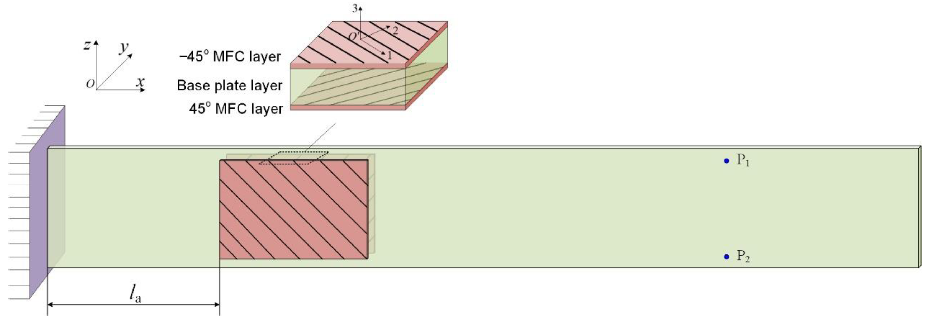
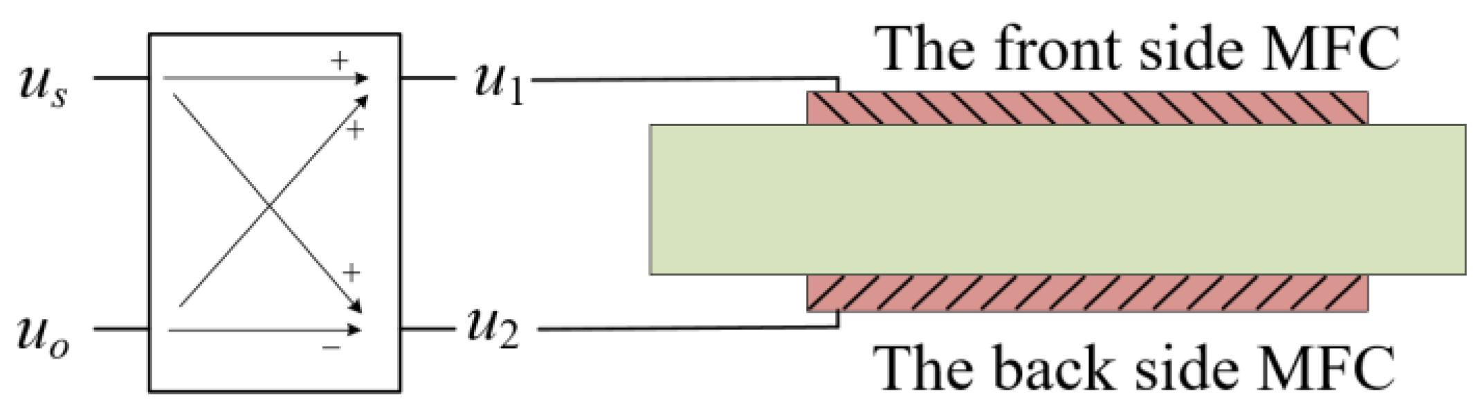
2.1. MFC-Actuated Plate Structures
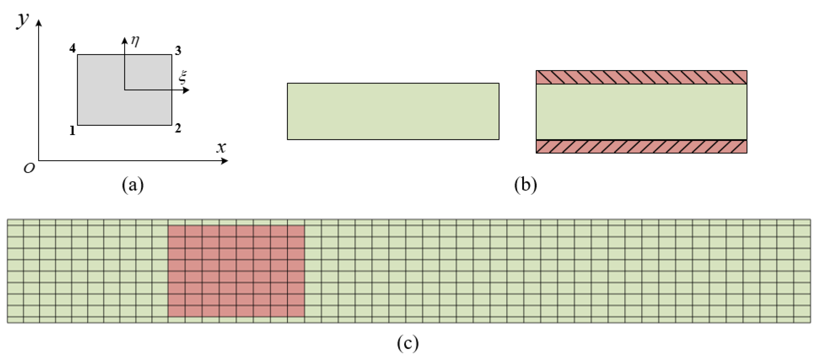
2.2. Finite Element Model
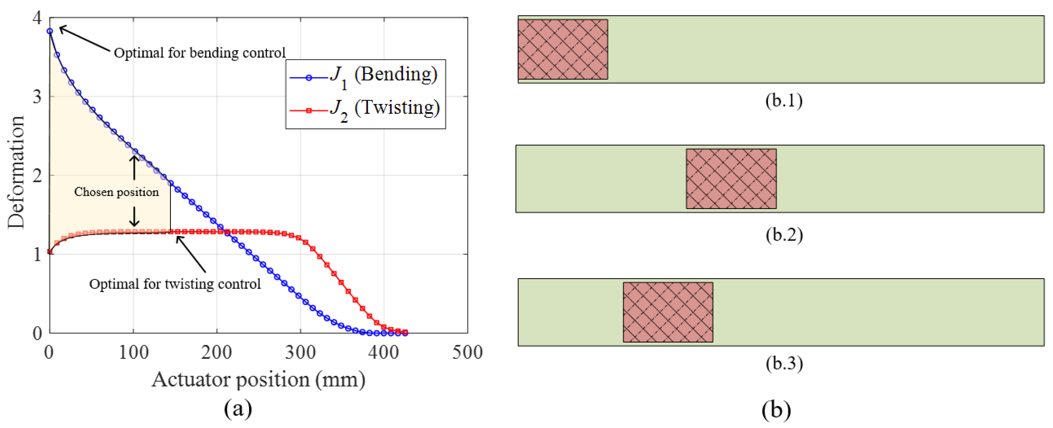
2.3. Actuator Position Optimization
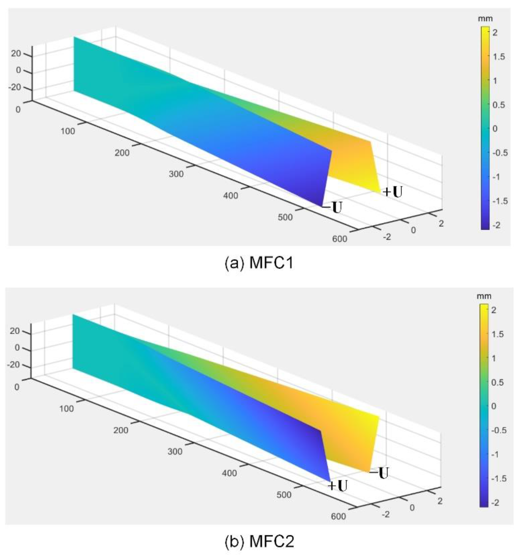
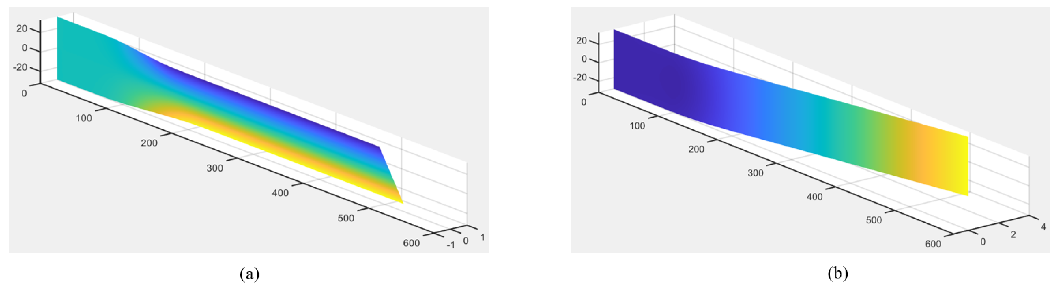
2.4. Theoretical Bending/Twisting Shape Control
3. Experiment Implementation
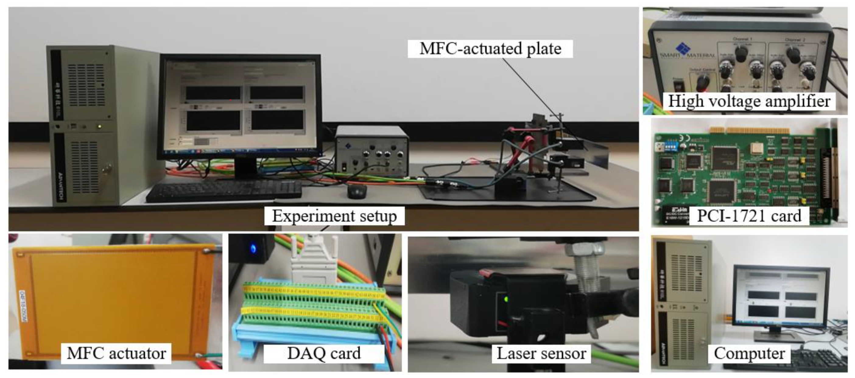
3.1. Setup
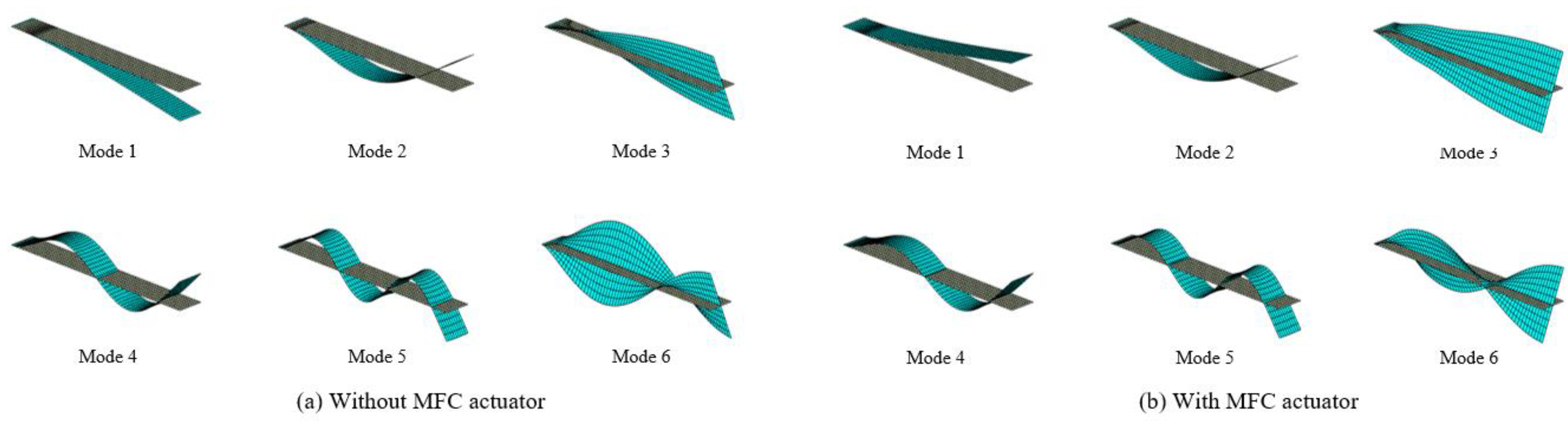
3.2. Modal Analysis
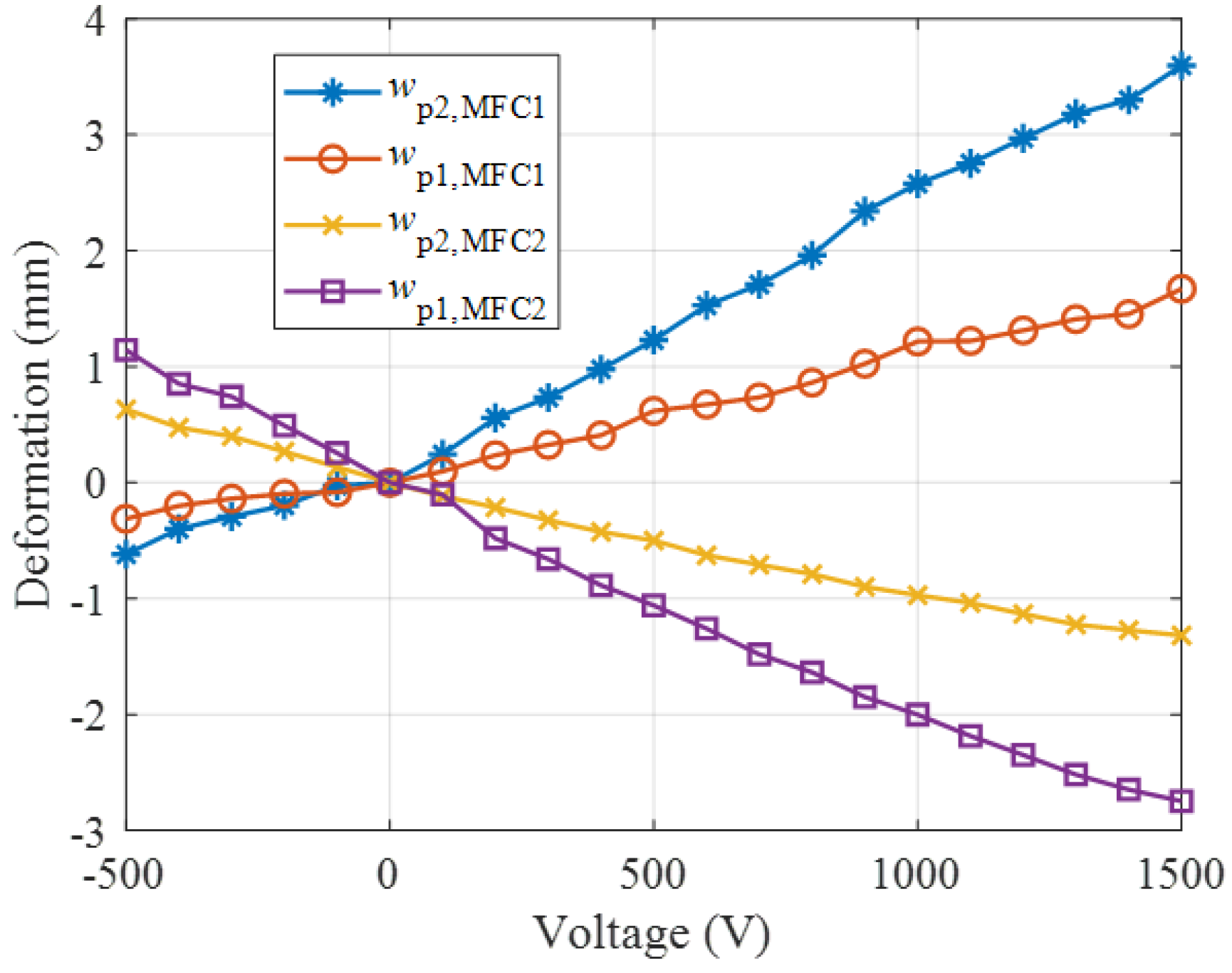
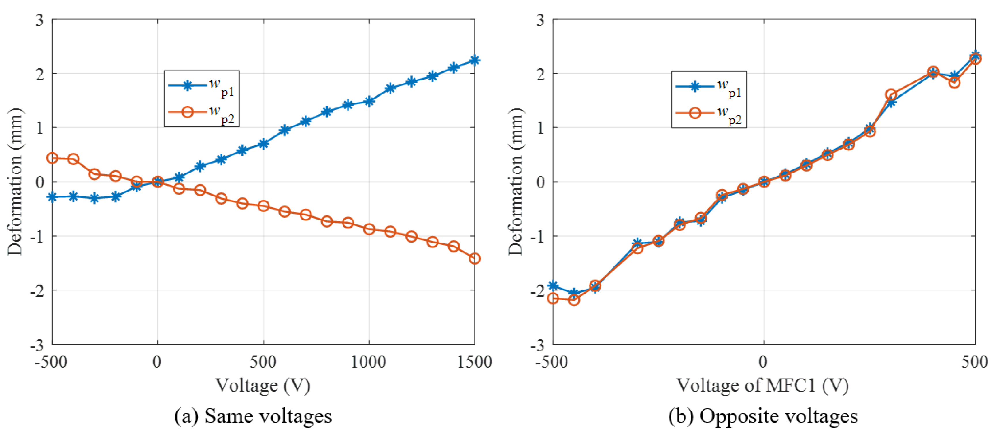
3.3. Control Ability
- (a)
- Using single MFC
- (b)
- Using bimorph MFCs
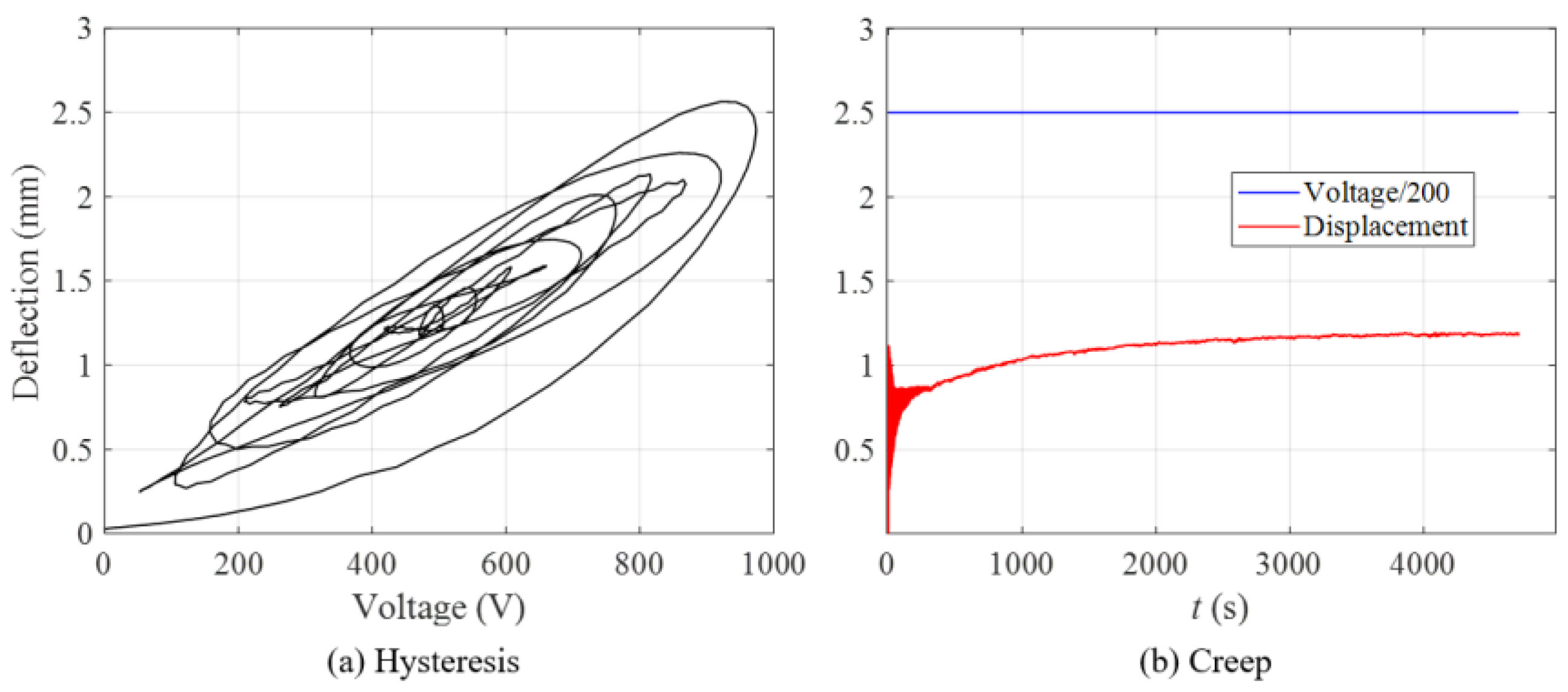
3.4. Uncertainty Analysis
4. Closed-Loop Multi-Mode Shape Control System
4.1. Feedback Control Law
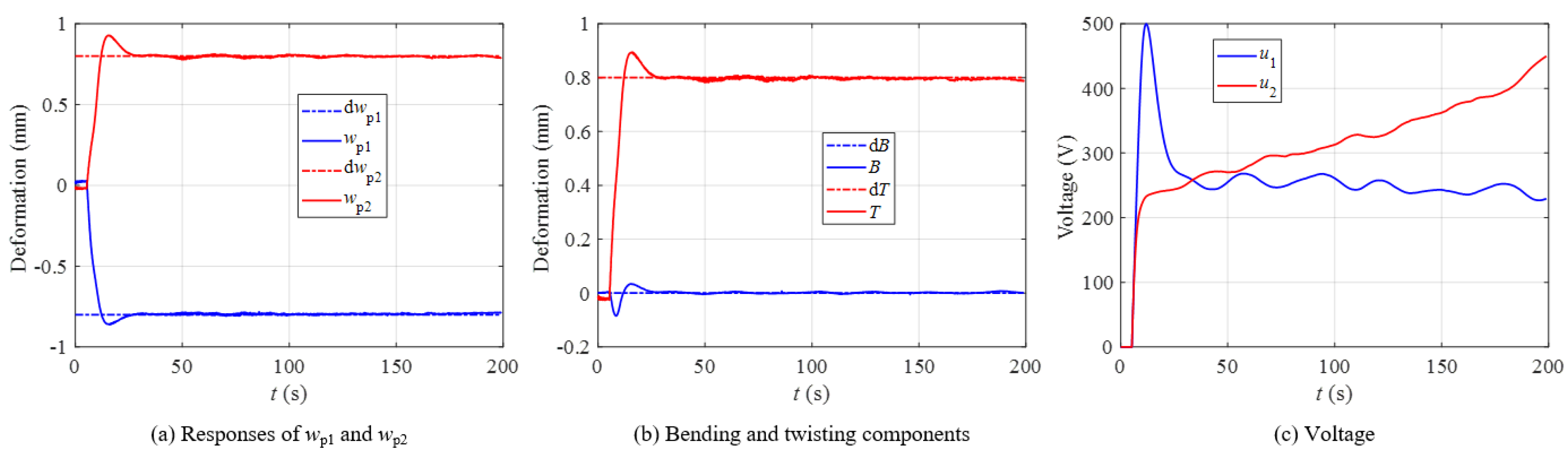
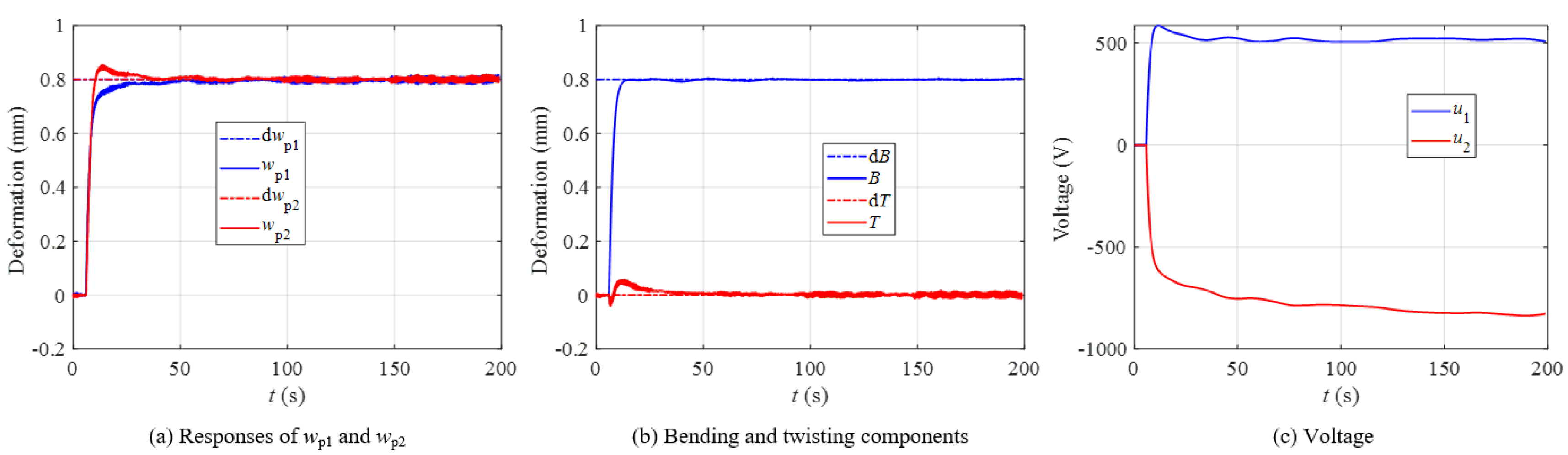
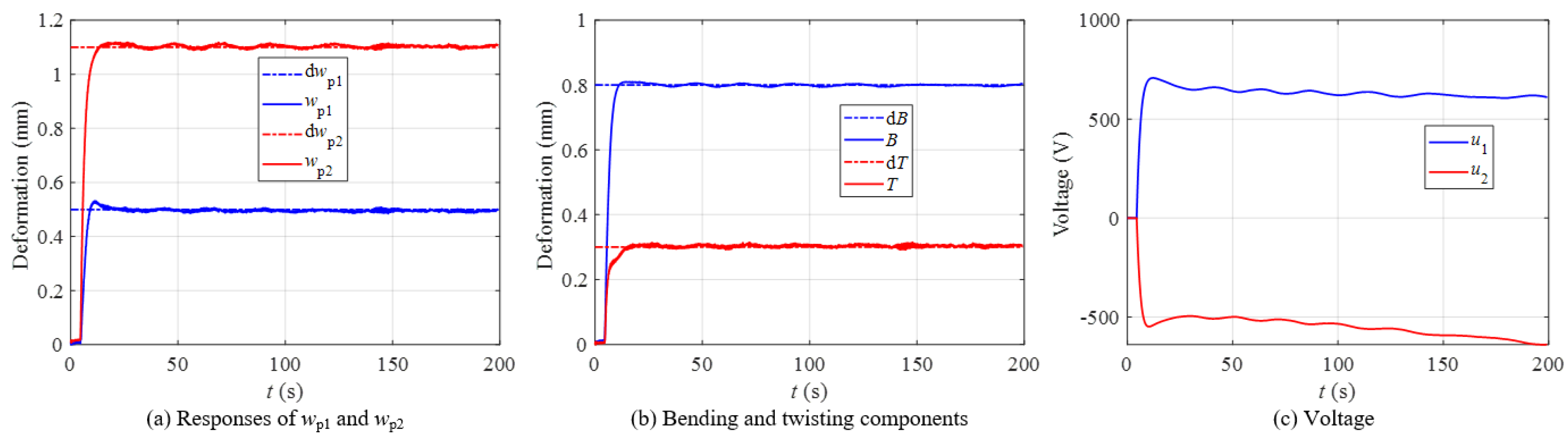
4.2. Multi-Mode Shape Control Results
5. Conclusions
Author Contributions
Funding
Institutional Review Board Statement
Informed Consent Statement
Data Availability Statement
Acknowledgments
Conflicts of Interest
References
- Barbarino, S.; Bilgen, O.; Ajaj, R.M.; Friswell, M.I.; Inman, D.J. A review of morphing aircraft. J. Intell. Mater. Syst. Struct. 2011, 22, 823–877. [Google Scholar] [CrossRef]
- Sun, J.; Guan, Q.; Liu, Y.; Leng, J. Morphing aircraft based on smart materials and structures: A state-of-the-art review. J. Intell. Mater. Syst. Struct. 2016, 27, 2289–2312. [Google Scholar] [CrossRef]
- Baier, H.; Datashvili, L. Active and morphing aerospace structures—A synthesis between advanced materials, structures and mechanisms. Int. J. Aeronaut. Space Sci. 2011, 12, 225–240. [Google Scholar] [CrossRef] [Green Version]
- Giurgiutiu, V. Review of smart-materials actuation solutions for aeroelastic and vibration control. J. Intell. Mater. Syst. Struct. 2000, 11, 525–544. [Google Scholar] [CrossRef]
- Ferreira, A.D.B.L.; Nóvoa, P.R.O.; Marques, A.T. Multifunctional material systems: A state-of-the-art review. Compos. Struct. 2016, 151, 3–35. [Google Scholar] [CrossRef]
- Bradford, S.C.; Agnes, G.S.; Ohara, C.M.; Green, J.J.; Shi, F.; Zhou, H. Controlling wavefront in lightweight active reflector systems using piezocomposite actuator arrays. In Proceedings of the 54th AIAA/ASME/ASCE/AHS/ASC Structures, Structural Dynamics and Materials Conference, Boston, MA, USA, 8–11 April 2013; AIAA: Reston, VR, USA, 2013. [Google Scholar]
- Shao, S.; Song, S.; Xu, M.; Jiang, W. Mechanically reconfigurable reflector for future smart space antenna application. Smart Mater. Struct. 2018, 27, 095014. [Google Scholar] [CrossRef]
- Bilgen, O.; Kochersberger, K.B.; Inman, D.J.; Ohanian, O.J. Novel, Bidirectional, Variable-Camber Airfoil via Macro-Fiber Composite Actuators. J. Aircr. 2010, 47, 303–314. [Google Scholar] [CrossRef]
- Echter, M.A.; Silver, M.J.; D’Elia, E.; Peterson, M.E. Recent Developments in Precision High Strain Composite Hinges for Deployable Space Telescopes. In Proceedings of the 2018 AIAA Spacecraft Structures Conference, Kissimmee, FL, USA, 8–12 January 2018; p. 14. [Google Scholar]
- Hill, J.; Wang, K.W.; Fang, H. Advances of Surface Control Methodologies for Flexible Space Reflectors. J. Spacecr. Rocket. 2013, 50, 816–828. [Google Scholar] [CrossRef]
- Wang, Z.; Li, T.; Cao, Y. Active shape adjustment of cable net structures with PZT actuators. Aerosp. Sci. Technol. 2013, 26, 160–168. [Google Scholar] [CrossRef]
- Song, X.; Tan, S.; Wang, E.; Wu, S.; Wu, Z. Active shape control of an antenna reflector using piezoelectric actuators. J. Intell. Mater. Syst. Struct. 2019, 30, 2733–2747. [Google Scholar] [CrossRef]
- Hiroaki, T.; Sakamoto, H.; Inagaki, A.; Ishimura, K.; Doi, A.; Kono, Y.; Kuratomi, T. Development of a smart reconfigurable reflector prototype for an extremely high-frequency antenna. J. Intell. Mater. Syst. Struct. 2016, 27, 764–773. [Google Scholar] [CrossRef]
- Sakamoto, H.; Tanaka, H.; Ishimura, K.; Doi, A.; Kono, Y.; Matsumoto, N. Shape-control experiment of space reconfigurable reflector using antenna reception power. In Proceedings of the 3rd AIAA Spacecraft Structures Conference, San Diego, CA, USA, 4–8 January 2016; p. 0703. [Google Scholar]
- Monner, H.P.; Riemenschneider, J.; Opitz, S.; Schulz, M. Development of active twist rotors at the German Aerospace Center (DLR). In Proceedings of the 52nd AIAA/ASME/ASCE/AHS/ASC Structures, Structural Dynamics and Materials Conference, Denver, CO, USA, 4–7 April 2011; AIAA: Reston, VR, USA, 2011. [Google Scholar]
- Riemenschneider, J.; Keye, S.; Wierach, P.; Mercier Des Rochettes, H. Overview of the common DLR/ONERA project “Active Twist Blade” (ATB). In Proceedings of the 30th European Rotorcraft Forum, Marseilles, France, Confederation of European Aerospace Societies, Brussels, Belgium, 14–16 September 2005; pp. 273–281. [Google Scholar]
- Li, M.; Chen, W.; Guan, D.; Li, W. Experimental validation of improving aircraft rolling power using piezoelectric actuators. Chin. J. Aeronaut. 2005, 18, 108–115. [Google Scholar] [CrossRef] [Green Version]
- Bilgen, O.; Kochersberger, K.; Diggs, E.C.; Kurdila, A.J.; Inman, D.J. Morphing wing micro-air-vehicles via macro-fiber-composite actuators. In Proceedings of the 48th AIAA/ASME/ASCE/AHS/ASC Structures, Structural Dynamics, and Materials Conference, Honolulu, HI, USA, 23–26 April 2007; AIAA: Reston, VR, USA, 2007; pp. 1005–1020. [Google Scholar]
- Bilgen, O.; Friswell, M.I. Piezoceramic composite actuators for a solid-state variable-camber wing. J. Intell. Mater. Syst. Struct. 2014, 25, 806–817. [Google Scholar] [CrossRef]
- LaCroix, B.W.; Ifju, P.G. Aeroelastic model for macrofiber composite actuators on micro air vehicles. J. Aircr. 2016, 54, 199–208. [Google Scholar] [CrossRef]
- Molinari, G.; Arrieta, A.F.; Ermanni, P. Aero-Structural Optimization of Three-Dimensional Adaptive Wings with Embedded Smart Actuators. AIAA J. 2014, 52, 1940–1951. [Google Scholar] [CrossRef]
- Usher, T.D.; Ulibarri, K.R., Jr.; Camargo, G.S. Piezoelectric microfiber composite actuators for morphing wings. ISRN Mater. Sci. 2013, 2013, 1–9. [Google Scholar] [CrossRef] [Green Version]
- Wetherhold, R.C.; Aldraihem, O.J. Bending and twisting vibration control of flexible structures using piezoelectric materials. Shock. Vib. Dig. 2001, 33, 187–197. [Google Scholar] [CrossRef]
- Ray, M.C.; Reddy, J.N. Active damping of laminated cylindrical shells conveying fluid using 1–3 piezoelectric composites. Compos. Struct. 2013, 98, 261–271. [Google Scholar] [CrossRef]
- Smith, W.A.; Auld, B.A. Modeling 1–3 composite piezoelectrics: Thickness-mode oscillations. IEEE Trans. Ultrason. Ferroelectr. Freq. Control 1991, 38, 40–47. [Google Scholar] [CrossRef]
- Choi, S.C.; Park, J.S.; Kim, J.H. Vibration control of pre-twisted rotating composite thin-walled beams with piezoelectric fiber composites. J. Sound Vib. 2007, 300, 176–196. [Google Scholar] [CrossRef]
- Bent, A.A.; Hagood, N.W.; Rodgers, J.P. Anisotropic actuation with piezoelectric fiber composites. J. Intell. Mater. Syst. Struct. 1995, 6, 338–349. [Google Scholar] [CrossRef]
- Kwak, S.K.; Yedavalli, R.K. New modeling and control design techniques for smart deformable aircraft structures. J. Guid. Control Dyn. 2001, 24, 805–815. [Google Scholar] [CrossRef]
- Wang, X.; Zhou, W.; Wu, Z.; Xing, J. Tracking control system design for roll maneuver via active wings using macro fiber composites. In Proceedings of the AIAA Modeling and Simulation Technologies Conference, Washington, DC, USA, 9–13 January 2017; AIAA: Reston, VR, USA, 2016. [Google Scholar]
- Smart-Material-Corporation. 2022. Available online: https://www.smart-material.com/MFC-product-mainV2.html (accessed on 30 March 2022).
- Bilgen, O.; Kochersberger, K.B.; Inman, D.J.; Ohanian, I.O.J. Lightweight high voltage electronic circuits for piezoelectric composite actuators. J. Intell. Mater. Syst. Struct. 2010, 21, 1417–1426. [Google Scholar] [CrossRef]
- Schröck, J.; Meurer, T.; Kugi, A. Control of a flexible beam actuated by macro-fiber composite patches–Part II: Hysteresis and creep compensation, experimental results. Smart Mater. Struct. 2011, 20, 015016. [Google Scholar] [CrossRef]
- Wickramasinghe, V.; Chen, Y.; Martinez, M.; Wong, F.; Kernaghan, R. Design and verification of a smart wing for an extreme-agility micro-air-vehicle. Smart Mater. Struct. 2011, 20, 125007. [Google Scholar] [CrossRef]
- Ohanian, O.J.; David, B.M.; Taylor, S.L.; Kochersberger, K.B.; Probst, T.; Gelhausen, P.A. Piezoelectric morphing versus servo-actuated MAV control surfaces, part II: Flight testing. In Proceedings of the 51st AIAA Aerospace Sciences Meeting Including the New Horizons Forum and Aerospace Exposition, Grapevine, TX, USA, 7–10 January 2013; AIAA: Reston, VR, USA, 2013. [Google Scholar]
- Wang, X.; Zhou, W.; Wu, Z. Feedback tracking control for dynamic morphing of piezocomposite actuated flexible wings. J. Sound Vib. 2018, 416, 17–28. [Google Scholar] [CrossRef]
- Wang, X.; Zhou, W.; Xun, G.; Wu, Z. Dynamic shape control of piezocomposite-actuated morphing wings with vibration suppression. J. Intell. Mater. Syst. Struct. 2018, 29, 358–370. [Google Scholar] [CrossRef]
- Zhou, W.; Wang, X.; Qian, W.; Wu, W. Optimization of Locations and Fiber Orientations of Piezocomposite Actuators on Flexible Wings for Aeroelastic Control. J. Aerosp. Eng. 2019, 32, 04019056. [Google Scholar] [CrossRef]
- Wang, X.; Zhou, W.; Wu, Z.; Wu, W. Optimal unimorph and bimorph configurations of piezocomposite actuators for bending and twisting vibration control of plate structures. J. Intell. Mater. Syst. Struct. 2018, 29, 1685–1696. [Google Scholar] [CrossRef]
- Wang, X.; Zhou, W.; Wu, Z.; Zhang, X. Integrated design of laminated composite structures with piezocomposite actuators for active shape control. Compos. Struct. 2019, 215, 166–177. [Google Scholar] [CrossRef]
- Williams, R.B.; Grimsley, B.W.; Inman, D.J.; Wilkie, W.K. Manufacturing and mechanics-based characterization of macro fiber composite actuators. In Proceedings of the ASME 2002 International Mechanical Engineering Congress and Exposition, New Orleans, LA, USA, 17–22 November 2002; ASME: New York, NY, USA, 2002; pp. 79–89. [Google Scholar]
- Zhang, S.-Q.; Li, Y.-X.; Schmidt, R. Modeling and simulation of macro-fiber composite layered smart structures. Compos. Struct. 2015, 126, 89–100. [Google Scholar] [CrossRef]
- Zhang, S.-Q.; Zhao, G.-Z.; Rao, M.N.; Schmidt, R.; Yu, Y.-J. A review on modeling techniques of piezoelectric integrated plates and shells. J. Intell. Mater. Syst. Struct. 2019, 30, 1133–1147. [Google Scholar] [CrossRef]
- Chee, C.Y.K.; Tong, L.Y.; Steven, G.P. A review on the modelling of piezoelectric sensors and actuators incorporated in intelligent structures. J. Intell. Mater. Syst. Struct. 1998, 9, 3–19. [Google Scholar] [CrossRef]
- Gupta, V.; Sharma, M.; Thakur, N. Optimization criteria for optimal placement of piezoelectric sensors and actuators on a smart structure: A technical review. J. Intell. Mater. Syst. Struct. 2010, 21, 1227–1243. [Google Scholar] [CrossRef]
- Frecker, M.I. Recent advances in optimization of smart structures and actuators. J. Intell. Mater. Syst. Struct. 2003, 14, 207–216. [Google Scholar] [CrossRef]
- Cao, Y.; Chen, X.B. A Survey of Modeling and Control Issues for Piezo-Electric Actuators. J. Dyn. Syst. Meas. Control Trans. ASME 2015, 137, 010101. [Google Scholar] [CrossRef]
- Wang, X.; Zhou, W.; Zhang, Z.; Jiang, J.; Wu, Z. Theoretical and experimental investigations on modified LQ terminal control scheme of piezo-actuated compliant structures in finite time. J. Sound Vib. 2021, 491, 115762. [Google Scholar] [CrossRef]


| Parameters | Values | |
|---|---|---|
| Base Plate | MFC Actuator [30] | |
| Length (mm) | 500 | 85 (active area) |
| Width (mm) | 64.5 | 57 (active area) |
| Thickness (mm) | 1 | 0.3 |
| Modulus of elasticity (GPa) | 70.3 | 30.34, 15.86 |
| Poisson’s ratio | 0.345 | 0.31, 0.16 |
| Density (kg/m3) | 2700 | 5400 |
| Actuator location | 100 mm from the root | |
| Measurement point locations | 105 mm from the tip | |
| Piezoelectric constants (m/V) | 400 × 10−12, −170 × 10−12 | |
| Fiber orientations (deg) | ±45° | |
| Electrode spacing | 0.5 mm | |
| Mode | Without MFC | With MFCs | ||||
|---|---|---|---|---|---|---|
| FEM | Experiment | Error | FEM | Experiment | Error | |
| 1st (bending) | 3.34 | 3.27 | 2.14% | 3.50 | 3.54 | −1.13% |
| 2nd (bending) | 20.89 | 20.53 | 1.75% | 19.57 | 19.51 | 0.30% |
| 3rd (torsional) | 49.90 | 46.63 | 5.80% | 53.30 | 52.89 | 7.80% |
| 4th (bending) | 58.59 | 58.17 | 0.72% | 54.40 | 57.45 | −5.30% |
Publisher’s Note: MDPI stays neutral with regard to jurisdictional claims in published maps and institutional affiliations. |
© 2022 by the authors. Licensee MDPI, Basel, Switzerland. This article is an open access article distributed under the terms and conditions of the Creative Commons Attribution (CC BY) license (https://creativecommons.org/licenses/by/4.0/).
Share and Cite
Wang, X.; Hu, X.; Huang, C.; Zhou, W. Multi-Mode Shape Control of Active Compliant Aerospace Structures Using Anisotropic Piezocomposite Materials in Antisymmetric Bimorph Configuration. Aerospace 2022, 9, 195. https://doi.org/10.3390/aerospace9040195
Wang X, Hu X, Huang C, Zhou W. Multi-Mode Shape Control of Active Compliant Aerospace Structures Using Anisotropic Piezocomposite Materials in Antisymmetric Bimorph Configuration. Aerospace. 2022; 9(4):195. https://doi.org/10.3390/aerospace9040195
Chicago/Turabian StyleWang, Xiaoming, Xinhan Hu, Chengbin Huang, and Wenya Zhou. 2022. "Multi-Mode Shape Control of Active Compliant Aerospace Structures Using Anisotropic Piezocomposite Materials in Antisymmetric Bimorph Configuration" Aerospace 9, no. 4: 195. https://doi.org/10.3390/aerospace9040195