Article

Design and Test of Dislocation Baffle Roller Bionic Picking Device for Fresh Corn

College of Mechanical and Electrical Engineering, Sichuan Agricultural University, Ya’an 625014, China
*
Author to whom correspondence should be addressed.
Agriculture 2023, 13(5), 991; https://doi.org/10.3390/agriculture13050991
Submission received: 3 April 2023 / Revised: 26 April 2023 / Accepted: 27 April 2023 / Published: 29 April 2023
(This article belongs to the Special Issue Agricultural Machinery Design and Agricultural Engineering)

Abstract

:
Considering the problems of the low mechanical work rate and the high picking damage rate of baffle roller bionic picking devices in the harvesting process of fresh corn in China, a method of fresh corn harvesting based on dislocation baffle roller bionic picking is proposed. When the picking device is in operation, the dislocation baffle roller assists with picking by applying deflecting torque to the corn cob. The mechanical properties of the bottom kernel were significantly better than those of the top kernel, according to the results of a triaxial compression test on fresh corn kernels, and the force applied by the picking device from the bottom kernel’s side could successfully prevent cob breakage. To determine the optimal combination of operating parameters for the bionic picking device, a three-factor, three-level virtual response surface optimization test was conducted using Box–Behnken’s central combination method with the baffle roller tilt angle, the baffle roller gap, and the stalk speed as the test factors, and the maximum contact force as the test indexes. Based on the theoretical analysis results, a test bench of the dislocation baffle roller bionic picking device was made. When the picking damage rate was 0.32%, the baffle roller dislocation was 5 mm, the baffle roller tilt angle was 41°, the baffle roller gap was 25 mm, and the stalk speed was 338 mm/s. This study can provide a reference for researching low-damage picking of fresh corn cob.

1. Introduction

Fresh corn is an important food and vegetable product widely planted in many countries and regions because of its deliciousness and nutritional value [1]. Fresh corn is often picked from the middle to the end of the milky stage [2,3], when the cobs have a high moisture content and a soft kernel coat, which can easily lead to cob gnawing when using a traditional corn header [4,5]. In order to reduce fresh corn picking damage and ensure its market worth, researchers have created a bionic picking device. They proposed a reverse-picking strategy based on the manual picking principle [6,7].
As agricultural machinery technology research progresses, agricultural machinery manufacturers worldwide have created fresh corn cob harvesters based on bionic picking technology and improved the efficiency of operations by combining various active cob picking roller configurations [8,9,10,11]. Researchers have conducted relevant research on the active picking roller structure and the stalk clamping and transporting device to increase the operational quality of the bionic picking device [12,13,14,15,16]. Liu and Zhang et al. [12,13,14] analyzed the bionic cob-picking process and established mathematical models of the critical picking components. The stalk-breaking issue was resolved by adding a stalk auxiliary conveying device, and a bench optimization test was used to explore the best parameter combinations for the cob picking device. Zhu et al. [15,16] researched the causes of stalk breakage caused by clamping by the bionic picking device, constructed a flexible clamping device based on stalk movement characteristics, and found that the stalk breakage rate was 0.55% when the clamping belt gap was 6 mm. Zhang et al. [17] simplified the structure of the bionic picking device and designed a baffle roller bionic picking device based on the cob bionic picking principle, and optimized the picking device parameters through field trials, with a final stalk feeding success rate of 83% and a cob damage rate of 4.7%. The cob-picking device’s interaction position with the cob is critical for minimizing cob-picking damage. Researchers have created a reverse bionic cob-picking device and a hand-style picking device that can both lessen the impact force on the cob and lessen cob-picking damage [18,19,20].
The baffle roller bionic picking device has the advantages of a simple structure and low energy consumption, but there is still room for improving the efficiency of its operation [17]. This research aims to optimize the working parameters of the baffle roller bionic picking device for fresh corn to enhance the corn-picking effect. Based on the theory of manual cob picking and the existing structure of a baffle roller bionic picking device, this paper proposes the structure of a dislocation baffle roller. Based on the ADAMS 2016 software platform, the virtual single factor test and response surface optimization test of bionic cob picking were performed. The optimal parameter combination of the dislocation baffle roller bionic cob picking device was obtained. Finally, a dislocation baffle roller bionic picking device test bench was built, and bench testing was used to confirm the reliability of the simulation test.

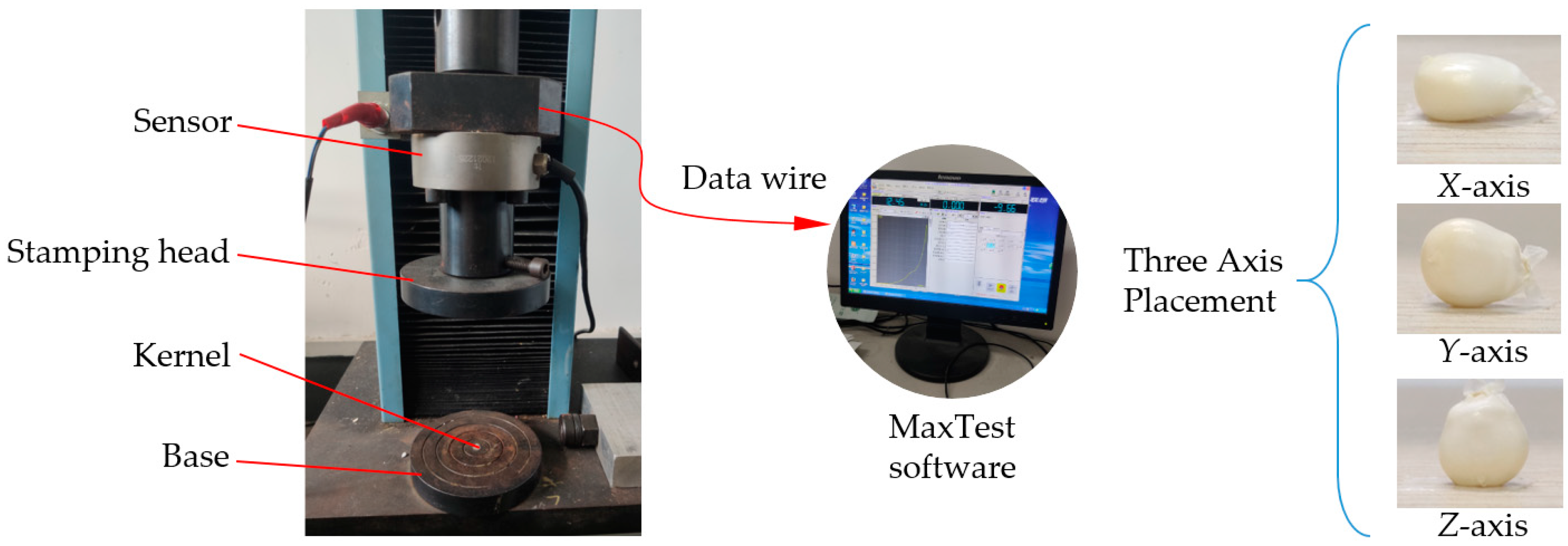
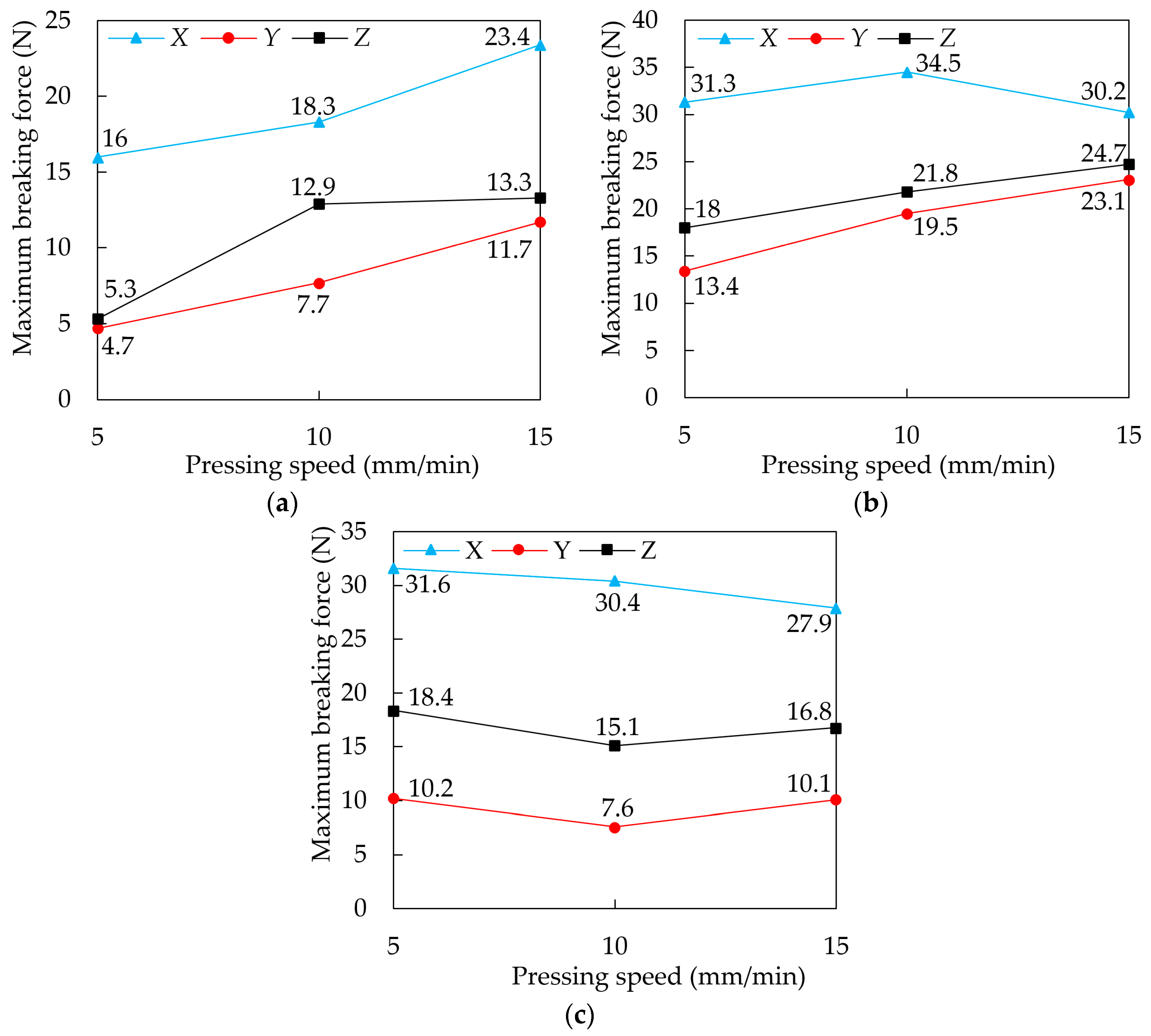
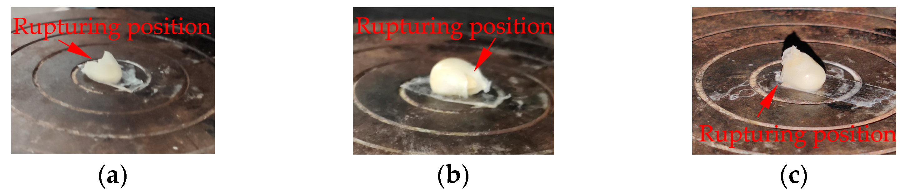
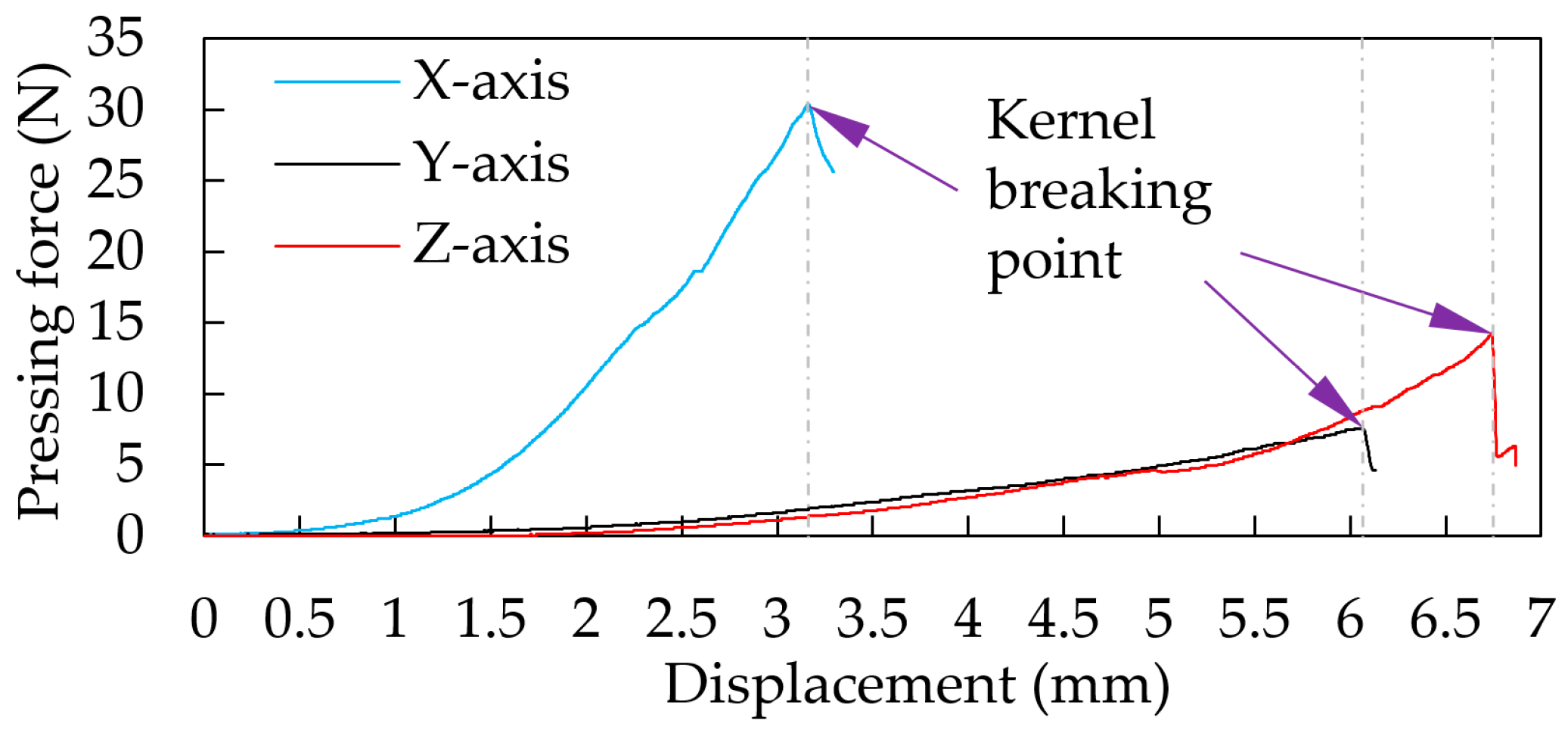
2. Mechanical Tests on Fresh Corn Kernel Crushing

The study used Lu Cainuo No. 8 fresh corn, which is extensively planted in Ya’an City; the average size parameters of fresh corn plants at maturity are shown in Table 1. The mechanical strength of the cob is directly influenced by the kernels’ mechanical strength, which is a crucial factor affecting the viability of mechanized fresh corn harvesting [21]. The fresh corn stalk utilized in the test had an average moisture content of 76.5%, and the kernels had a moderate moisture content of 67.3%.
In order to analyze the mechanical properties of kernels in different parts of fresh corn cobs, kernel samples were collected from the bottom, middle, and top of the cob and subjected to triaxial compression testing. The MaxTest software regulates the downward movement speed of the universal testing machine’s stamping head (WDW-05 type) to produce a squeezing effect on the kernels, and the force-displacement curve of the kernels is output after the test. The kernel is fixed to the base with double-sided adhesive to prevent it from rolling when it encounters the stamping head, as shown in Figure 1.
The stamping head was set to 5 mm/min, 10 mm/min, and 15 mm/min, and the kernel was fixed to the base in the X, Y, and Z coordinate directions. The test results are illustrated in Figure 2.
Figure 2 shows that the maximum crushing force is generated in the X-axis direction and the minor crushing force is generated in the Y-axis direction in all three portions of cob, and the maximum crushing force is 23.4 N for the top kernels, 34.5 N for the middle kernels, and 31.6 N for the bottom kernels.
Due to the functional characteristics of the bionic picking device, the bottom kernels of the fresh corn cob are readily squeezed during picking, so the bottom kernels are chosen as the subject of research on the trend of kernel fragmentation by force. When the bottom kernels are compressed in the Y-axis and Z-axis directions, the maximum crushing force decreases and then increases as the downward pressure speed increases; when the bottom kernels are compressed in the X-axis direction, the maximum crushing force gradually decreases as the downward pressure speed increases. Figure 3 depicts the damage caused when the bottom kernels are stressed in different directions.
As shown in Figure 2, the bottom kernels are most vulnerable to damage when the pressure speed is 10 mm/min. Under this speed condition, the force-displacement curve of the bottom kernel in the triaxial direction is shown in Figure 4.
According to Figure 4, when the bottom kernels are crushed along the X-axis, the crushing force quickly rises, the deformation is minimal, and the kernels exhibit the highest compressive strength. In the Y-axis direction, where the kernel’s mechanical strength is the lowest, external forces can easily damage the kernel. Based on how the force breaks the bottom kernels, the picking device can minimize picking damage by touching the kernels from the X-axis direction.

3. Design and Analysis of Dislocation Baffle Roller Bionic Picking Device

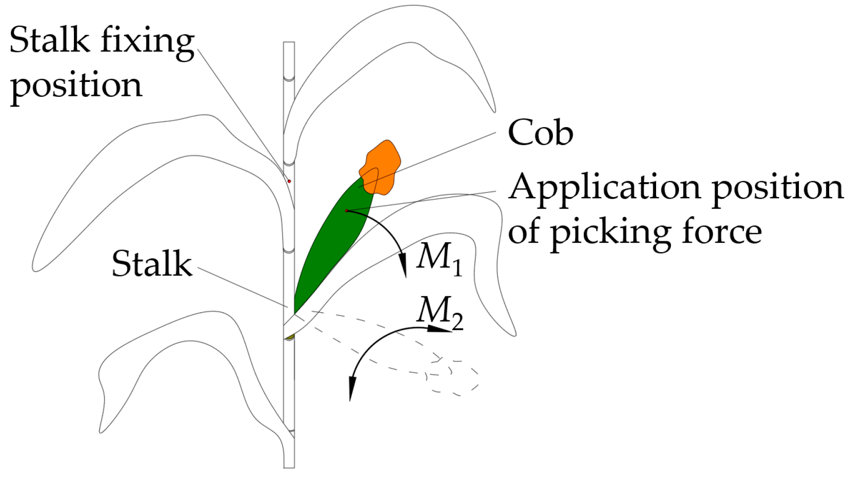
3.1. Analysis of Bionic Picking Principle

When manually picking the cobs, grab the stalk at the top of the cob with one hand so that the stalk can provide support counterforce for the picking action. The cobs are picked from top to bottom by the other hand. When the corn cob is bent, the hand exerts a rotational force until it falls. The manual picking process is shown in Figure 5.
Existing bionic cob-picking devices imitate fixing the stalks by hand through the clamper and use the friction of the clamping belt to drive the fresh corn plant to move backward. Fresh corn bionic picking devices use pairs of combined picking rollers/a picking baffle roller structure, two rollers in the same plane, a picking-action that is only a cob-roller impact action, it cannot provide rotational torque for cob picking, and it is not conducive to improving cob-picking efficiency.

3.2. Structure Design of Dislocation Baffle Roller Picking Device

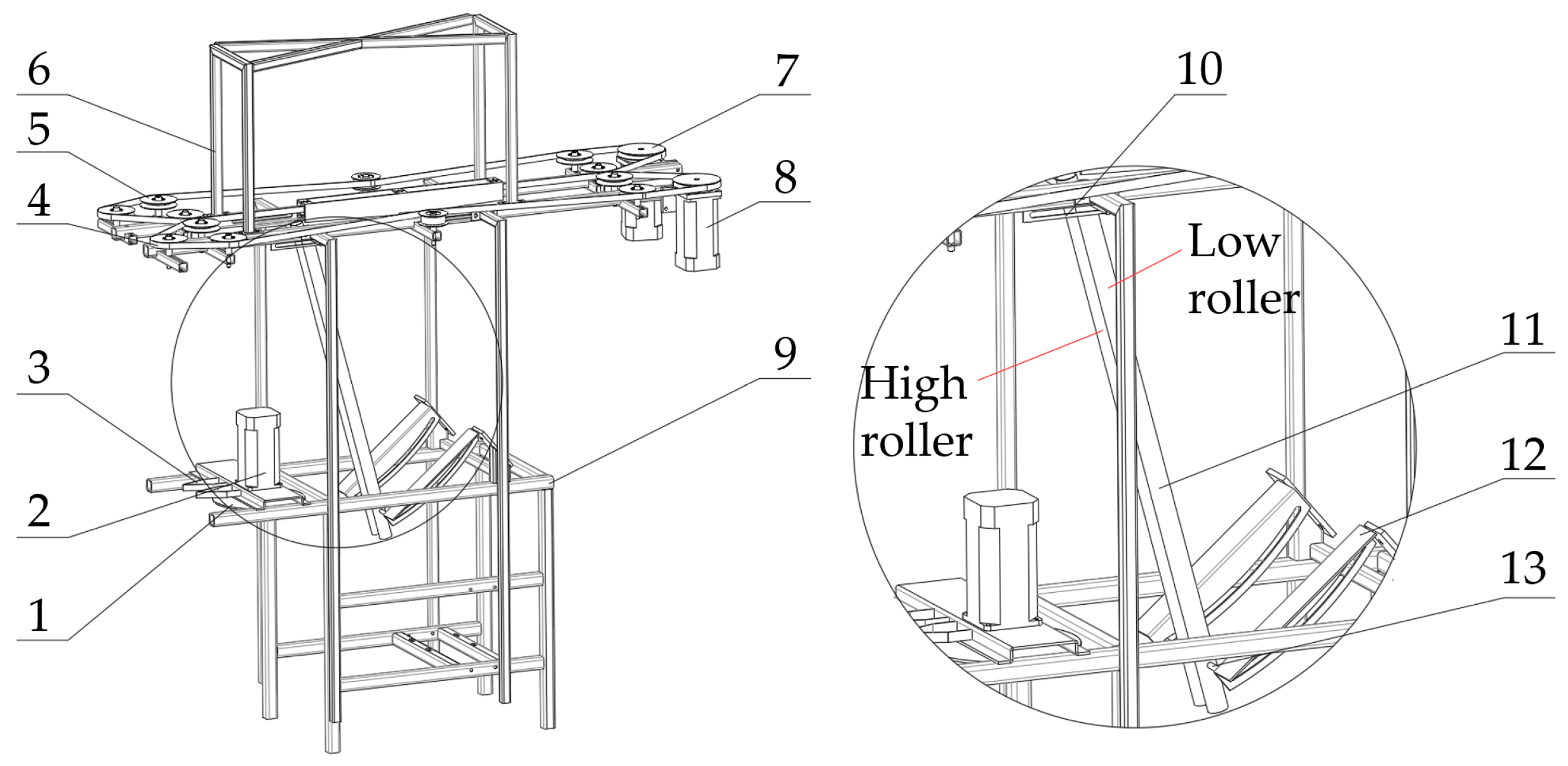
3.2.1. Overall Structural Design

This research presents a dislocation baffle roller bionic picking method based on the manual picking principle analysis results. When the cobs hit the picking roller, the difference between the left and right baffle roller high and low positions produces a deflection torque on the cobs from the high baffle roller to the low baffle roller to assist in picking. The overall structure of the dislocation baffle roller picking device is shown in Figure 6, which mainly includes the stalk clamper, stalk cutter, picking baffle roller, and frame. The picking cob baffle roller has no power drive mechanism, but the dislocation, gap, tilt angle, and other parameters can be modified.

3.2.2. Working Principle

Fresh corn plants are fed to the front of the picking device during the cob-picking operation, and the plants are captured by the clamping belt and travel backwards. The fresh corn plant first comes into touch with the cutter, and then the cob encounters the cob-picking baffle roller. The stalk continues to migrate backward when the cob is picked. The main technical parameters of the bionic picking device were determined based on the picking operation requirements, as indicated in Table 2.

3.3. Design of Key Components

3.3.1. Design of Clamper

In order to reduce the deflection displacement of the stem caused by the cutter and the degree of difference between the plant feeding position and the expected state, it is necessary to minimize the displacement and angle of deflection of the stalk around the clamping place, and the clamping belt gap should not be larger than the natural diameter of the stalk being clamped. The cob node diameter of Lu Cainuo No. 8 fresh corn stalk was 12 mm, the diameter of the first node above the cob node was 10 mm, and the diameter of the second node above the cob node was 8 mm. Because the stalk clamping location is not higher than the second node at the top of the cob in this study, the clamping belt gap is 5 mm. The stalk clamping operation process is shown in Figure 7.
The process of the stalk clamping action satisfies the following:
σ 1 = 0 t ω 1 d t v 1 = ω 2 R 1 v 2 = H ω 1 v 3 = v 1 = ( H + Δ h ) ω 1 Δ h = ω 2 ω 1 R 1 H
where R1 is the radius of the driving wheel of the clamping belt, mm; ω2 is the angular speed of rotation of the driving wheel of the clamping belt, rad/min; v2 is the linear velocity of the clamped position when the stalk is first clamped, m/s; v3 is the linear velocity of the clamped position when the stalk first touches the cutter, m/s.
The driving wheels for the left and right clamping belts are the same size and have a 40-mm radius in order to prevent the left and right clamping belts from moving at different speeds. When the clamping belt speed is known, the appropriate increase in clamped height can reduce the stalk deflection angle and slip displacement, and increase the stalk clamping efficiency. The relationship between the stalk position state during picking and the clamping height and clamping belt speed is shown in Equation (1).

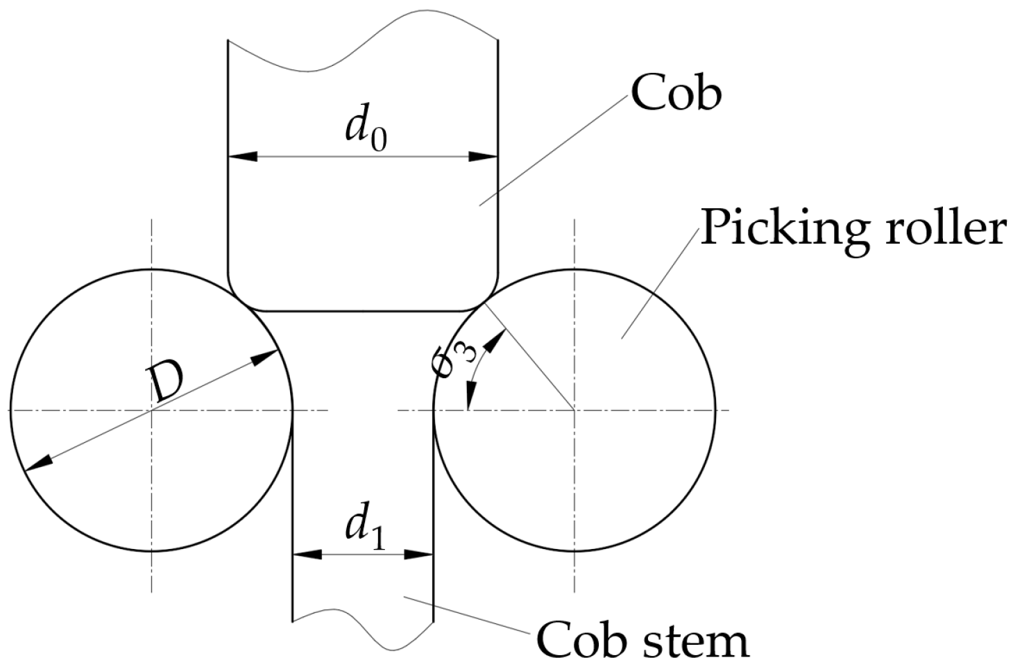
3.3.2. Design of Picking Baffle Roller

The impact effect between the picking baffle roller and the cob should be maximized in the cob picking action, so the picking baffle roller is just able to grasp the cob as the limit position, cob-roller grasping action, as shown in Figure 8.
Figure 8 shows that in the limit state, the following relationships exist between the diameter of the picking baffle roller and the diameter of the stalk, the diameter of the cob, and the diameter of the cob stem:
D < d 0 d 1 1 cos σ 3
where d0 is the diameter of the large end of the corn cob, which is 51 mm in this paper; d1 is the diameter of the cob stem, which is 23 mm in this paper; d2 is the picking baffle roller gap, mm; D is the diameter of the picking baffle roller, mm; σ3 is the initial gripping angle of the picking baffle roller to the cob, (°).
Because the initial gripping angle of the picking baffle roller to the cobs is determined to be 60°, and the diameter of the picking baffle roller should be less than 56 mm, the diameter of the designed picking baffle roller is 40 mm.

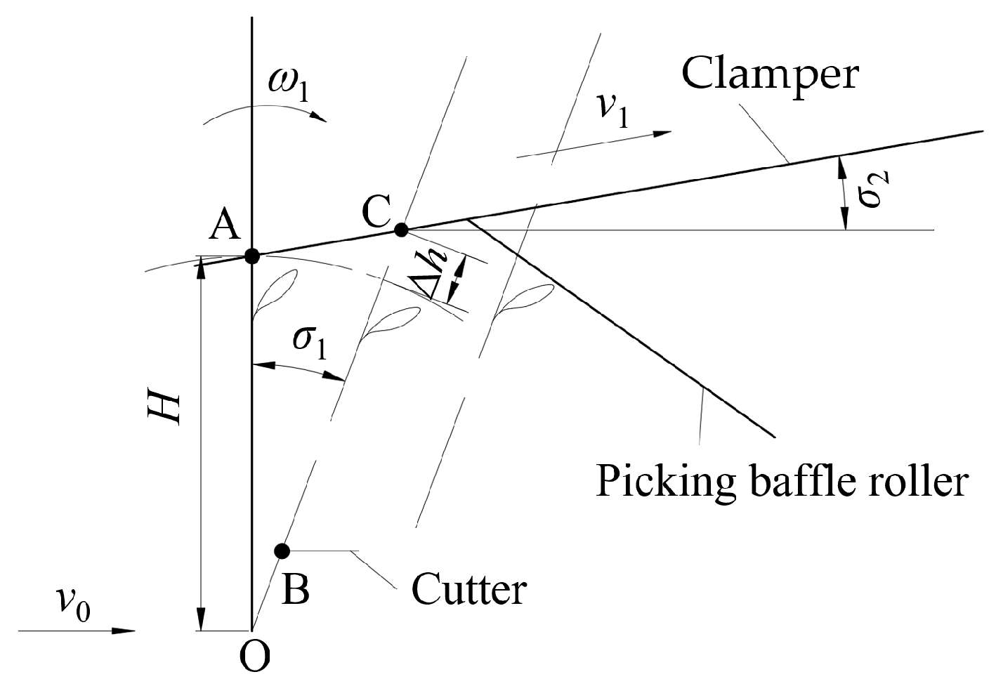
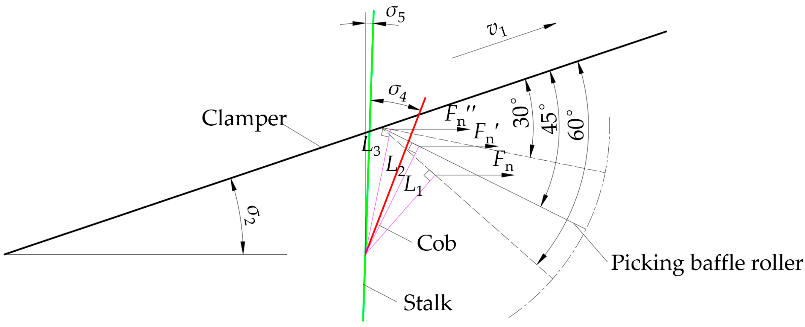
3.3.3. Analysis of the Picking Baffle Roller Tilt Angle

A baffle roller tilt adjustment mechanism is developed to accommodate the needs of diverse cob harvesting tilt angles. Figure 9 depicts the relationship between the cob-roller action during the operation of the bionic cob-picking device under different cob-picking baffle roller tilt angles.
The rate of rise of the effective bending force arm of the cob is more significant at a baffle roller tilt angle of 45°–60° than at a baffle roller tilt angle of 30°–45°, as shown in Figure 9.
L 2 L 1 > L 3 L 2 M 1 = F n L 1 M 2 = F n L 2 M 3 = F n L 3
where M1 is the bending torque of the cob when the tilt angle of the picking baffle roller is 60°, Nm; M2 is the bending torque of the cob when the tilt angle of the picking baffle roller is 45°, Nm; M3 is the bending torque of the cob when the tilt angle of the picking baffle roller is 30°, Nm.
The movement speed, mass, clamped position of the stalk, and impact force produced by the impact between the cob and the baffle roller are all the same. The larger the tilt angle of the picking baffle roller, the smaller the effective bending force arm of the cob-roller, and thus, the smaller the adequate picking torque. The picking torque directly affects picking efficiency. When the tilt angle of the picking baffle roller is too narrow, the force of the top kernels of the cobs encountering the picking baffle roller is greater, and the cobs are more likely to experience damage. Therefore, the tilt angle of the picking baffle roller should not be less than 30°.

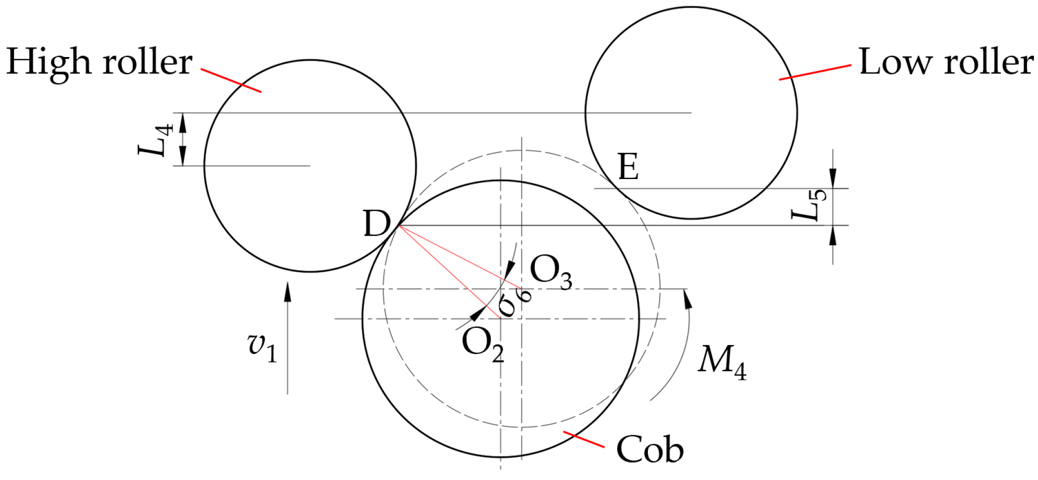
3.3.4. Force Analysis of Cob-Roller

The cob produces a lateral torque from the high roller to the low roller as a result of the dislocation structure of the baffle roller’s high and low places. The action relationship between the picking baffle roller and the cob are shown in Figure 10.
In this study, the cobs’ sliding distance is disregarded, and the rotation of the cob around point D satisfies the following conditions:
L 4 = 0 t 1 v 1 d t σ 6 = 0 t 1 ω 3 d t M 4 = m 0 d 0 2 2 σ 6 2 d t
where ω3 is the angular speed of rotation of the cob around point D, rad/min; m0 is the mass of the cob, kg.
The time between the cob’s impact with the left and right baffle rollers increase with the cob rotation angle. According to the momentum-pulse theorem, the bionic picking cob process complies with Equation (5).
I = F t = 0 t M a ( t ) d t
where M is the effective picking moment to which the cob is subjected, Nm; a is the initial acceleration of the cob, m/s2; Δt is the cob picking time, s.
As shown in Equation (5), under the same cob-picking force conditions, the longer the cob-roller contact time, the less force on the kernel and the less damage to the cobs.

4. Bionic Corn Cob Picking Simulation Test

ADAMS software is widely used in automotive engineering, mechanical engineering, aerospace engineering, agricultural engineering, and other sectors, and a vast number of study cases have demonstrated its excellent analytical dependability [22,23,24,25]. In this study, the dislocation baffle roller’s cob-picking process is simulated using the ADAMS software, and vital statistics, including picking contact force and picking time, are exported using a post-processing function to serve as a theoretical benchmark for subsequent optimizing work.

4.1. Simulation Model Building and Constraint Handling

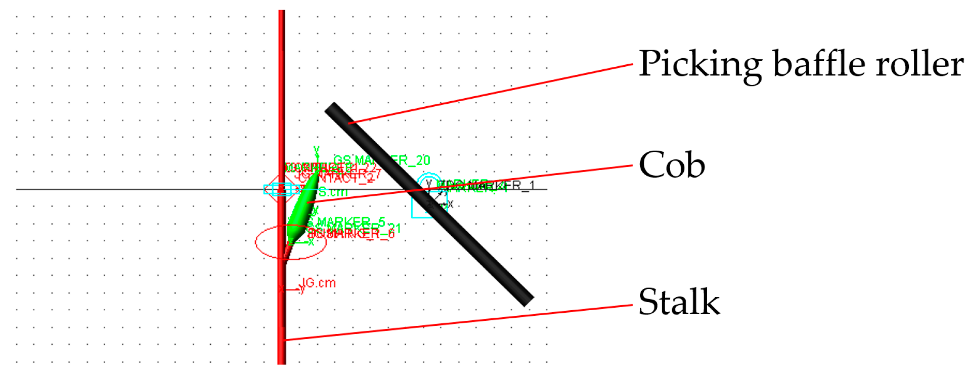
4.1.1. Simulation Model

The position relationship between the fresh corn plant and the bionic picking device was used to establish a bionic picking cob analysis model, which was then imported into ADAMS software, as shown in Figure 11.
The material was added to the fresh corn plant and the picking baffle roller, respectively; the material parameters are shown in Table 3 [26].

4.1.2. Analytical Model Pre-Processing Settings

The fresh corn plant interacts with the picking baffle roller while being pulled by the clamper after being divided by the cutter, according to the analysis of the bionic picking device’s picking process. This study fixes the picking baffle roller, sets the speed of the corn plant, and relies on the impact action of the cob-roller to achieve the picking action.
(1)
The solid-solid contact mode was defined for the contact between the cob and the picking baffle roller, and the contact parameters are listed in Table 4 [27].
(2)
Set the bushing force between the cob and the stalk, with the core of the cob stem end face as the center of the bushing force. The parameters of the bushing force are shown in Table 5.
(3)
Add a translational motion for the stalk. Add a translation drive for the stalk to the moving pair, and the driving speed is the linear speed of the clamping belt, and the X direction is the travel direction. The clamping belt’s linear speed satisfies the following:
v 4 = w 2 R 1
When the speed of the clamping belt is 400 rad/min, the moving speed of the stalk is 270 mm/s. Similarly, other stalk moving speeds can be obtained according to the clamping belt rotation speed.
(4)
Create a new force measuring tool. Measure the combined force on the bushing force.
(5)
Create a new sensor. When the total force of the bushing force exceeds 500 N, the bushing force fails, and the cob-picking activity is finished.

4.2. Single Factor Virtual Simulation Test

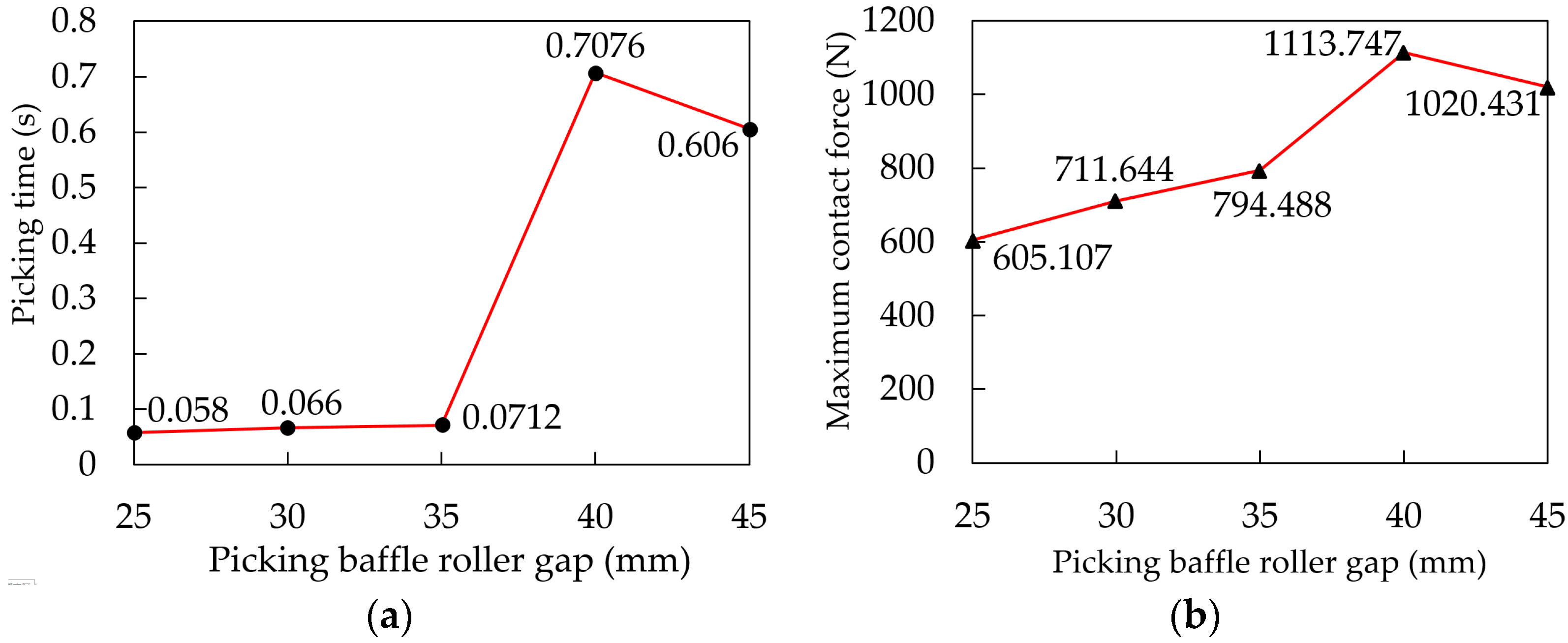
4.2.1. Single Factor Virtual Simulation Test of Picking Baffle Roller Gap

The picking baffle roller gap is the most crucial factor influencing stalk passing rate and cob picking efficiency. Five levels of distance between baffle rollers were chosen based on the diameter of the stalk and the diameter of the large end of the cob: 25 mm, 30 mm, 35 mm, 40 mm, and 45 mm. Set the picking baffle roller tilt angle to 45°, the picking baffle roller dislocation to 10 mm, and the stalk speed to 270 mm/s before doing the single factor simulation test of the picking baffle roller gap. The test results are shown in Figure 12.
The cob picking time initially increases before decreasing, as shown in Figure 12a, when the picking baffle roller gap increases. Corn cobs are plucked in a single impact when the distance between the picking rollers is less than 40 mm. The cob will experience a secondary impact phenomenon when the picking baffle roller gap is higher than 40 mm, which causes the cob picking time to be significantly increased. As shown in Figure 12b, as the picking baffle roller gap rises, the maximum contact force increases at first and gradually declines. Based on the maximum contact force and cob-picking time, the gap adjustment interval of the baffle roller is set to 25–35 mm for subsequent optimization tests.

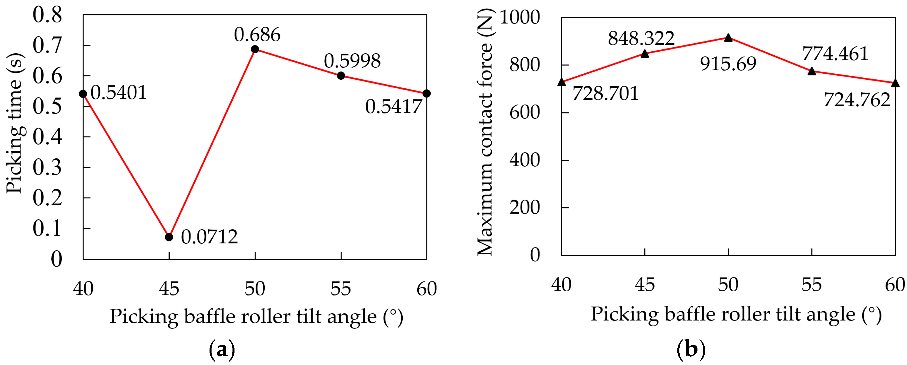
4.2.2. Single Factor Virtual Simulation Test of Picking Baffle Roller Tilt Angle

The tilt angle of the baffle roller has a significant effect on the picking torque. Five levels, namely 40°, 45°, 50°, 55°, and 60°, were chosen for a single factor simulation test of the baffle roller tilt angle in order to investigate the effect of the angle of the baffle roller on the picking time and the maximum contact force of the cob. The test results are shown in Figure 13.
Figure 13a shows that as the baffle roller tilt angle increases, the picking time initially decreases and subsequently increases. The smallest value is attained when the baffle roller tilt angle is 45°, and the cob can complete the picking action in a single impact. As shown in Figure 13b, as the baffle roller tilt angle increases, the maximum contact force increases at first and gradually declines. This is because when the tilt angle is 50°, the cob receives the most rotational torque, and the cob contact force is most significant. The adjustment range of the baffle roller tilt angle was determined to be 40°–50° for the following optimization tests by combining the maximum contact force and the picking time.

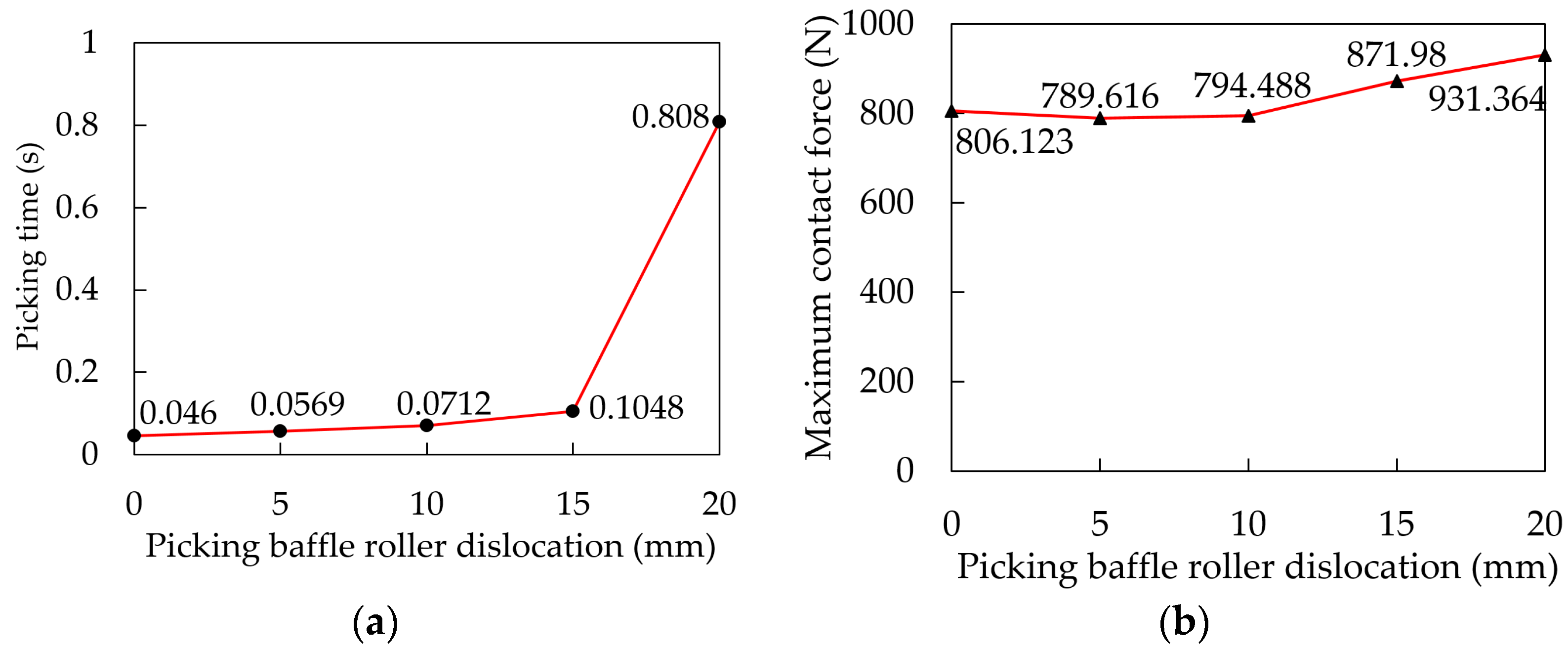
4.2.3. Single Factor Virtual Simulation Test of Picking Baffle Roller Dislocation

The previous investigation indicated that the dislocation height of the picking baffle roller is a significant factor influencing the cob picking damage. To find the optimum roller dislocation, the effects of baffle roller dislocation on cob-picking time and maximum contact force were investigated. The picking baffle roller dislocation was tested using a single factor simulation at five different levels: 0 mm, 5 mm, 10 mm, 15 mm, and 20 mm, and the results are displayed in Figure 14.
As shown in Figure 14a, the cob picking time steadily increased as the picking baffle roller dislocation increased. When the picking baffle roller dislocation was greater than 15 mm, the cob could not be successfully picked under the action of a single impact, resulting in secondary impact damage to the cobs. As shown in Figure 14b, as the picking baffle roller dislocation rises, the maximum contact force reduces first and subsequently increases. According to the picking baffle roller dislocation single factor test findings, the picking time is short when the roller baffle dislocation is 5 mm, and the cob can be successfully picked in a single impact.

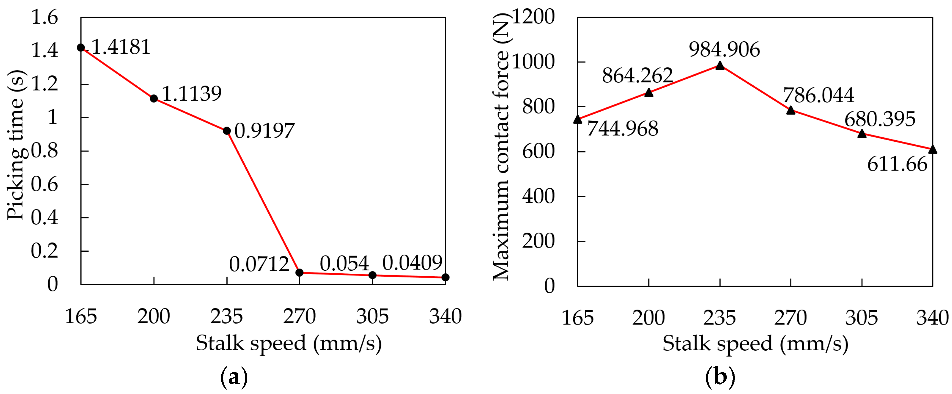
4.2.4. Single Factor Virtual Simulation Test of Picking Baffle Roller Stalk Speed

In order to study the effect of stalk speed on picking time and maximum contact force, a single factor simulation test was performed at five stalk speed levels: 165 mm/s, 200 mm/s, 235 mm/s, 270 mm/s, and 305 mm/s. The test results are shown in Figure 15.
As shown in Figure 15a, as stalk speed increases, picking time steadily decreases. When the stalk speed exceeds 270 mm/s, the cob can be successfully harvested with a single impact, avoiding secondary impact damage. The maximum contact force and picking time were combined to establish the range of stalk movement speed, which was found to be 270–340 mm/s.

4.3. Cob Bionic Picking Virtual Response Surface Test

4.3.1. Test Design and Results

The Box-Behnken response surface test was carried out using the baffle roller tilt angle (A), baffle roller gap (B), and stalk speed (C) as test variables, and the maximum contact force as a test indicator, with a fixed picking baffle roller dislocation of 5 mm. The factor level of the response surface test was determined based on the results of the single factor test, as indicated in Table 6. Table 7 shows the test plans and results after rounding off the maximum contact force measured in the test.

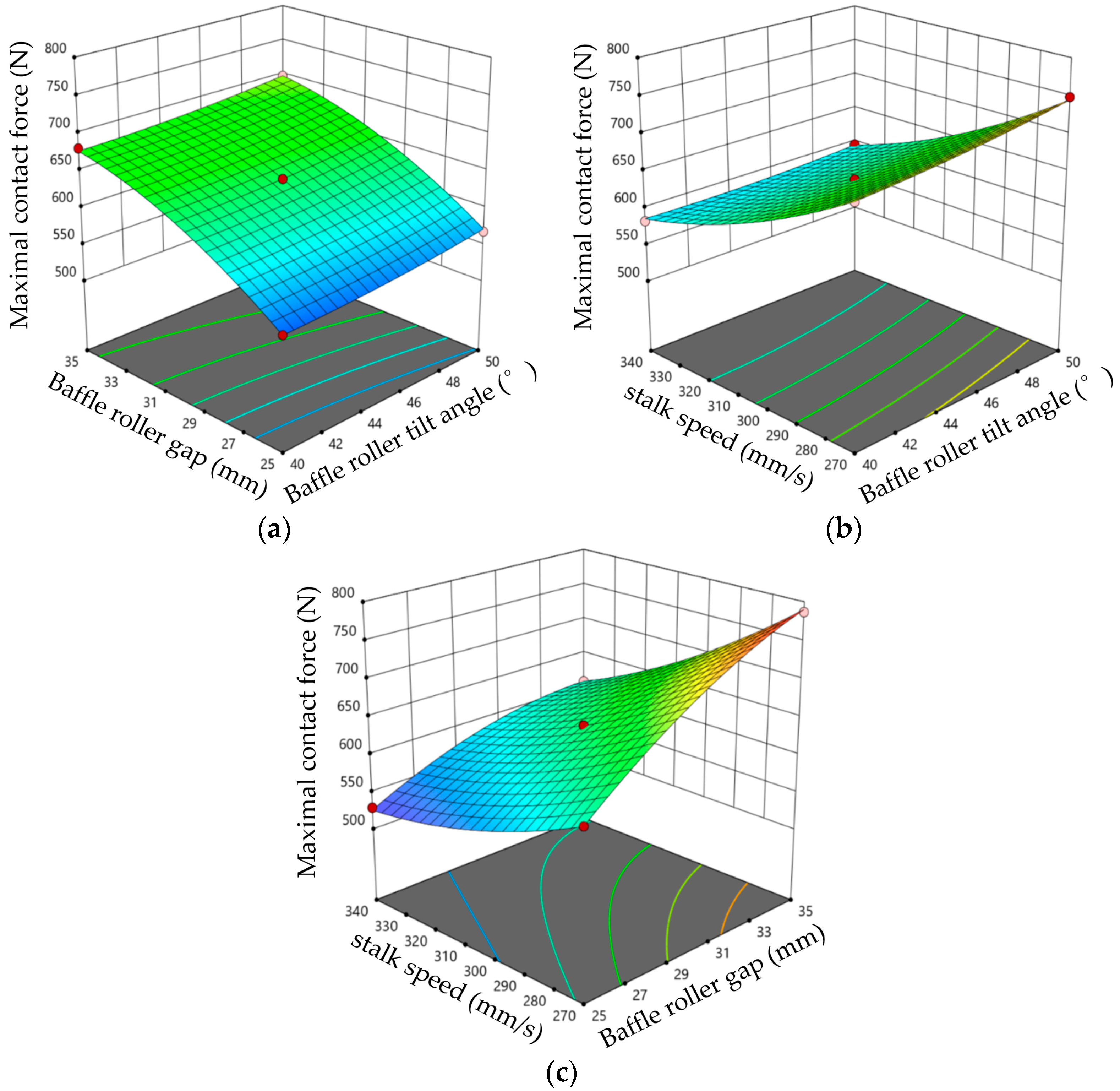
4.3.2. Result Analysis

We used Design-Expert 11 software to conduct variance analysis in Table 7; the results are given in Table 8.
Table 8 shows that the maximum contact force regression model’s significance test value (p < 0.01) demonstrates that the maximum contact force regression model is extremely significant. Due to simulation environment restrictions, evaluating the duplicate error is impossible. Except for the interaction item AB, which is insignificant, the maximum contact force regression model is significant. The significance of the influence of each variable on the maximum contact force is in the following order, from more to less significant: the stalk speed, the baffle roller gap, and the baffle roller tilt angle.
After eliminating the non-significant factors, the quadratic regression equation of each variable on the maximum contact force was obtained, as shown in Equation (7):
Y 1 = 3.87 A 2 19.63 B 2 + 15.88 C 2 6.25 A C 21.75 B C + 10.75 A + 63.5 B 68.75 C + 640
The interaction of the three test factors on the maximum contact force is shown in Figure 16.
The minimum maximum contact force was chosen as the constraint condition, and Design-Expert 11 software was used to solve the regression equation Y1. The optimal parameter combination was obtained: baffle roller tilt angle 40.6°, baffle roller gap 25.0 mm, stalk speed 338.1 mm/s. The maximal contact force of the cob under these conditions was 525.4 N.

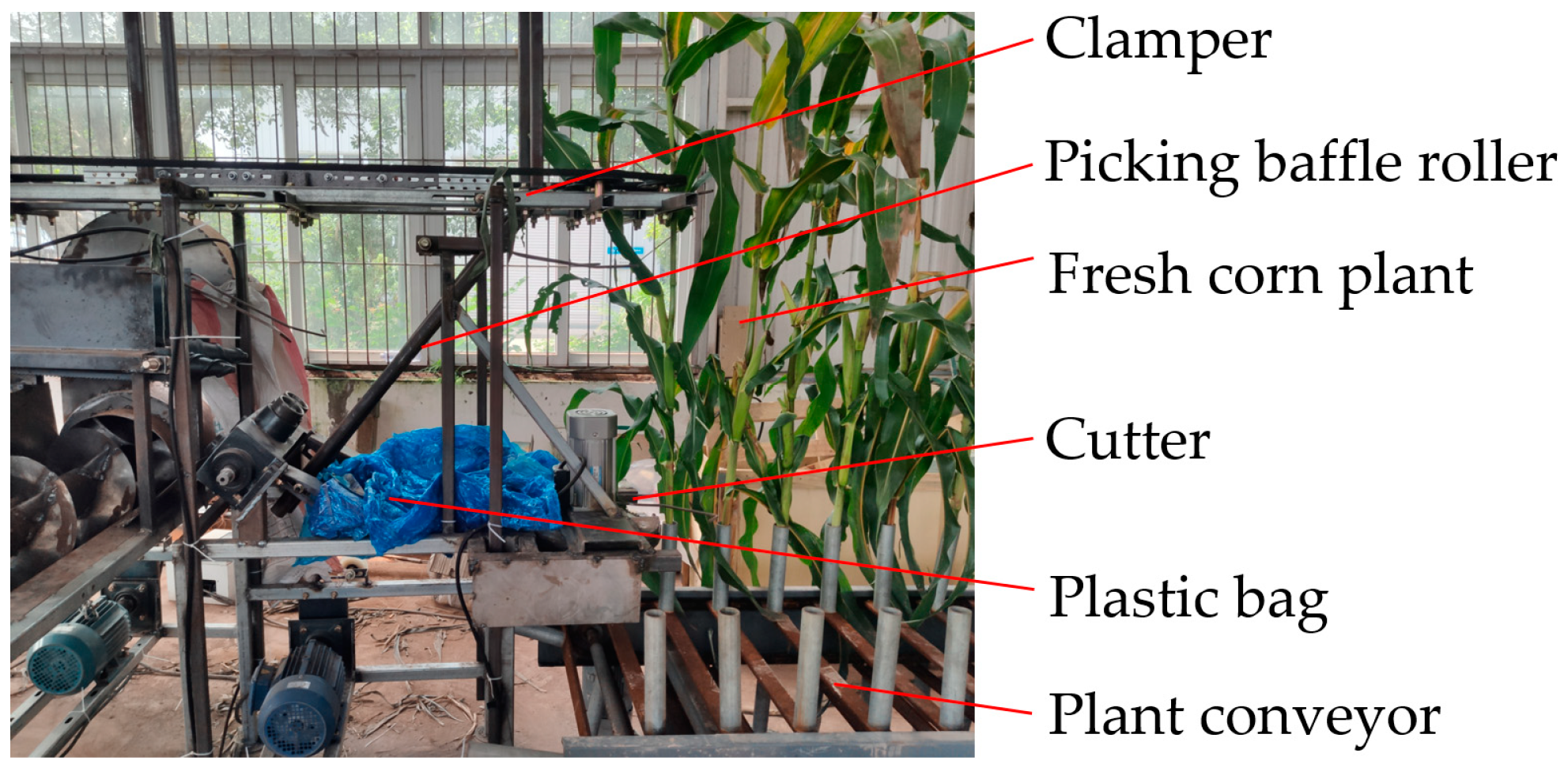
5. Bench Verification Test

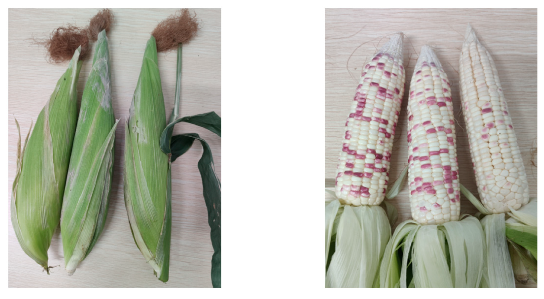
5.1. Test Materials and Devices

Based on theoretical research, a bionic cob picking test bench was built, which included a dislocation picking baffle roller, a stalk clamper, a stalk cutter, a stalk conveying device, a driving motor, and a frequency converter (US-750 type). The bionic cob-picking test bench is shown in Figure 17.
The test material was Lu Cainuo No. 8 fresh corn plant grown in Ya’an City, and the corn plant was in the middle to the end of the milky stage during the test. The average diameter of the stalk was 23 mm, the average moisture content of the stalk was 76.5%, and the average moisture content of the kernel was 67.3%. The test was completed within 10 h of gathering fresh corn plants.

5.2. Test Parameter and Indicator

Set the picking baffle roller dislocation to 5 mm before the test. Using the tilt angle adjusting device, set the baffle roller tilt angle to 41°. Using the baffle roller gap adjustment device, adjust the baffle roller gap to 25 mm. Using a frequency converter, set the rotation speed of the clamping belt motor to 507 rad/min, resulting in a stalk movement speed of 338 mm/s. Modify the test bench’s operational parameters to the best parameter combination. A buffer plastic bag is placed behind the cob picking baffle roller to prevent secondary damage caused by cob-picking. When the cob is picked, it directly falls into the plastic bag to reduce test error.
Because fresh corn kernels have a high moisture content and are difficult to peel, the percentage of damaged kernels in harvested kernels is computed by dividing the number of damaged kernels by the total number of kernels. The calculation formula is as follows.
S = Z 1 Z 0
where Z0 is the total number of kernels per cob; Z1 is the number of damaged kernels after picking.
According to statistics, each corn kernel has 17 rows, and each row has 33 kernels. The standard specifies a total of 561 kernels per cob.

5.3. Test Results and Phenomenon Analysis

The test was divided into five groups, each testing ten corn plants, for a total of 50 plants. After the test, the damaged corn cobs were selected from each group, and the damage rate of a single corn cob was calculated and averaged. The test results are shown in Table 9, and the corn cob-picking effect of the bionic picking device is shown in Figure 18.
As shown in Table 9, the verification test’s average picking damage rate was 0.32%, significantly lower than the relevant provisions of the national standard GB/T 21962-2020 Corn Harvesting Machinery. The damage rate of the dislocation baffle roller bionic picking device designed in this study was reduced by 93.2% compared to the goal damage rate of 4.7%, satisfying the requirements of low damage picking operation for fresh corn.

6. Conclusions

(1)
The triaxial compression test on fresh Lu Cainuo No. 8 corn cob revealed that the highest crushing forces of the bottom, middle, and top kernels were 31.55 N, 34.45 N, and 23.40 N, respectively. The bottom kernel had the greatest compression strength along the X-axis, whereas the kernel had the lowest compression strength along the Y-axis. The bionic picking device contacts the kernel from the X direction, which can effectively reduce the cob-picking damage.
(2)
Based on ADAMS software, a three-factor, three-level response surface test was conducted, using the maximum contact force as the test index and the baffle roller tilt angle, baffle roller gap, and stalk speed as test variables. With the minimum maximum contact force as the constraint condition, the regression equation Y1 is solved to obtain the parameter combination of the baffle roller tilt angle of 40.6°, the baffle roller gap of 25.0 mm, and the stalk speed of 338.1 mm/s. At this time, the maximum contact force of the corn cob was 525.4 N, which ensured the minimization of cob-picking damage.
(3)
According to the theoretical analysis results, the dislocation picking baffle roller bionic picking test bench was trial-produced, and a bench verification test was carried out after rounding off the optimal parameter combination. The test results show that a baffle roller dislocation of 5 mm, a baffle roller tilt angle of 41°, a baffle roller gap of 25 mm, a stalk speed of 338 mm/s parameter combinations, a picking damage rate of 0.32%, is obviously lower than the optimization target of 4.7% and the national standards, meeting the requirements of low-damage picking operation of fresh corn.

Author Contributions

Conceptualization, L.Z. and H.L.; methodology, H.L.; software, J.N. and H.L.; validation, H.L.; formal analysis, L.Z.; investigation, L.Z. and H.L.; resources, H.L.; data curation, H.L. and J.N.; writing—original draft preparation, H.L.; writing—review and editing, L.Z., J.N. and H.L.; funding acquisition, J.N. All authors have read and agreed to the published version of the manuscript.

Funding

This research was funded by the China Agriculture Research System (CARS-02).

Institutional Review Board Statement

Not applicable.

Informed Consent Statement

Informed consent was obtained from all subjects involved in the study.

Data Availability Statement

The data presented in this study are available upon request from the authors.

Conflicts of Interest

The authors declare no conflict of interest.

References

  1. Agackesen, M.N.; Oktem, A.G.; Oktem, A. Effect of Harvest at Different Maturation Stages on Fresh Ear Yield and Ear Characteristics of Sweet Corn (Zea mays L. saccharata) Genotypes. Appl. Ecol. Environ. Res. 2022, 20, 3335–3351. [Google Scholar] [CrossRef]
  2. Chen, X.; Rong, M.; Guo, Y.; Xu, Z.; Wang, Q.; Yu, X.; Xin, Y.; Jia, X.; Jiang, L. Qualitative Dynamics of Waxy Maize (Jikenuo 19) in Different Harvest Times. Bangladesh J. Bot. 2021, 50, 987–992. [Google Scholar] [CrossRef]
  3. Lu, B.; Dong, H.; Xu, L.; Shi, Y.; Zhao, J.; Fan, Y.; Yu, A. Relationship Between Water Content and Physical Properties and Quality of Sweet Corn at Different Harvesting Periods. Acta Agric. Boreali-Sin. 2019, 34, 69–77. [Google Scholar]
  4. Zhang, Z.; Chi, R.; Du, Y.; Pan, X.; Dong, N.; Xie, B. Experiments and Modeling of Mechanism Analysis of Maize Picking Loss. Int. J. Agric. Biol. Eng. 2021, 14, 11–19. [Google Scholar] [CrossRef]
  5. Wang, X.; Geng, L.; Li, X.; Pang, J.; Zhou, H. Design and Experiment of Low-injury Picking Test Table for Fresh-eating Maize. Agric. Eng. 2017, 7, 68–71. [Google Scholar]
  6. Paulson, B.S.; Paulson, B.H. Fresh Market Sweet Corn Harvester. U.S. Patent 5661964, 2 September 1997. [Google Scholar]
  7. Wolf, I.; Alper, Y.; Michai, G. Development of a Harvester for Fresh-market Sweet Corn. Hassadeh Q. 1990, 1, 32–34. [Google Scholar]
  8. CP100-Oxbo International Corp [EB/OL]. Available online: https://oxbo.com/products/oxbo-cp100/ (accessed on 21 February 2023).
  9. CP400-Oxbo International Corp [EB/OL]. Available online: https://oxbo.com/products/oxbo-cp400/ (accessed on 21 February 2023).
  10. Sweet Corn Harvest Machine|OSADA Agricultural Machinery Company [EB/OL]. Available online: http://www.osada-nouki.co.jp/corn.html (accessed on 22 February 2023).
  11. Liu, C.; Zhang, X.; Liu, T.; Liu, T.; Wu, P. Development Status of Sweet Corn Harvesting Machinery in China. Intern. Combust. Engine Parts 2018, 224–226. [Google Scholar]
  12. Liu, C. Research and Study on Key Technology of Fresh Corn Harvesting Header. Master’s Thesis, Jilin University, Changchun, China, 2019. [Google Scholar]
  13. Zhang, L.; Yu, J.; Zhang, Q.; Liu, C.; Fang, X. Design and Experimental Study of Bionic Reverse Picking Header for Fresh Corn. Agriculture 2023, 13, 93. [Google Scholar] [CrossRef]
  14. Zhang, L.; Yu, J.; Zhang, Q.; Fang, X. Design and Testing of a New Bionic Corn-Ear-Picking Test Device. Appl. Sci. 2023, 13, 838. [Google Scholar] [CrossRef]
  15. Zhu, G.; Li, T.; Zhou, F. Design and Experiment of Flexible Clamping and Conveying Device for Bionic Ear Picking of Fresh Corn. J. Jilin Univ. Eng. Technol. Ed. 2022, 52, 2486–2500. [Google Scholar]
  16. Zhu, G.; Li, T.; Zhou, F.; Wang, W. Design and Experiment of Bionic Ear Picking Device for Fresh Corn. J. Jilin Univ. Eng. Technol. Ed. 2022, 12, 1953. [Google Scholar]
  17. Zhang, X.; Wu, P.; Wang, K.; Li, Y.; Shang, S.; Zhang, X. Design and Experiment of 4YZT-2 Type Self-propelled Fresh Corn Double Ridges Harvester. Trans. Chin. Soc. Agric. Eng. 2019, 35, 1–9. [Google Scholar]
  18. Zhang, H.; Chen, B.; Li, Z.; Zhu, C.; Jin, E.; Qu, Z. Design and Simulation Analysis of a Reverse Flexible Harvesting Device for Fresh Corn. Agriculture 2022, 12, 1953. [Google Scholar] [CrossRef]
  19. Chen, M.; Cheng, X.; Jia, X.; Zhang, L.; Li, Q. Optimization of Operating Parameter and Structure for Corn Ear Picking Device by Bionic Breaking Ear Hand. Trans. Chin. Soc. Agric. Eng. 2018, 34, 15–22. [Google Scholar]
  20. Zhang, L.; Li, Q. Speed of Bionic Breaking Corn Ear Hand and Experiment on Power Consumption. Trans. Chin. Soc. Agric. Eng. 2015, 31, 9–14. [Google Scholar]
  21. Zhang, T.; Liang, T.; Li, P.; Liu, K.; Zhang, X.; Tang, X.; Li, Y. Study on Basic Physical Properties and Mechanical Damage Rule of Maize Seeds. Seed 2021, 40, 46–53. [Google Scholar]
  22. Zhang, G.; Wei, Y.; Ju, C.; He, S. Multiobjective Optimization of Vehicle Handling and Stability Based on ADAMS. Math. Probl. Eng. 2022, 2022, 3245251. [Google Scholar] [CrossRef]
  23. Shu, C.; Cao, S.; Liao, Y.; Liao, Q.; Wan, X.; Li, Y. Parameter Optimization and Experiment of Forward Laying Device for Rape Windrower Based on ADAMS. Trans. Chin. Soc. Agric. Mach. 2022, 53, 11–19. [Google Scholar]
  24. Cheng, H.; Gao, L.; Liu, Z.; Liu, Q. Dynamic Modeling and Braking Performance Optimization of Multi-axle Special Vehicle. J. Vib. Shock. 2021, 40, 241–248. [Google Scholar]
  25. Kanchwala, H.; Chatterjee, A. ADAMS model validation for an all-terrain vehicle using test track data. Adv. Mech. Eng. 2019, 11, 2072155066. [Google Scholar] [CrossRef] [Green Version]
  26. Zhang, L. Theoretical Analysis and Simulation Research on Novel Corn-Ear Snapping Mechanism. Master’s Thesis, Jilin University, Changchun, China, 2015. [Google Scholar]
  27. Du, Y.; Mao, E.; Song, Z.; Zhu, Z.; Gao, J. Simulation on Corn Plants at Harvesting Process Based on ADAMS. Trans. Chin. Soc. Agric. Mach. 2012, 43, 106–111. [Google Scholar]
Figure 1. Test bench for mechanical properties of fresh corn kernel.
Agriculture 13 00991 g001
Figure 2. Results of triaxial compression test on fresh corn kernel. (a) Top kernel; (b) Middle kernel; (c) Bottom kernel.
Agriculture 13 00991 g002
Figure 3. Damage form of the bottom kernel. (a) X-axis placement; (b) Y-axis placement; (c) Z-axis placement.
Agriculture 13 00991 g003
Figure 4. Bottom kernel force-displacement curve.
Agriculture 13 00991 g004
Figure 5. Diagram of manual picking cob. M1 is the bending torque applied to the cob, Nm; M2 is the rotating torque applied to the cob, Nm.
Agriculture 13 00991 g005
Figure 6. Diagram of the dislocation baffle roller bionic picking device structure. (1) Cutter, (2) Cutter motor, (3) Divider, (4) Clamping belt, (5) Tensioning wheel, (6) Clamper holder, (7) Driving wheel, (8) Clamping belt motor, (9) Frame, (10) Baffle roller top tilt angle adjustment plate, (11) Baffle roller, (12) Baffle roller bottom tilt angle adjustment plate, (13) Clearance adjustment bolt.
Agriculture 13 00991 g006
Figure 7. Analysis of clamping operation process. Δh is the slip displacement before the stalk was cut, mm; σ1 is the rotation angle before the stalk was cut, (°); σ2 is the clamper tilt angle, (°); v0 is the stalk feeding speed, m/s; v1 is the clamping belt line speed, m/s; ω1 is the stalk rotation angular speed, rad/min; point A is the stalk clamping position; point B is the stalk cutting position; point C is the stalk clamping position after the cutting action is completed.
Agriculture 13 00991 g007
Figure 8. Diagram of cob-roller gripping action.
Agriculture 13 00991 g008
Figure 9. Diagram of the cob-roller action relationship. L1 is the effective bending force arm of the cobs and the baffle roller when the tilt angle of the picking baffle roller is 60°, mm; L2 is the effective bending force arm of the cobs and the baffle roller when the tilt angle of the picking baffle roller is 45°, mm; L3 is the effective bending force arm of the cobs and the baffle roller when the tilt angle of the picking baffle roller is 30°, mm; σ4 is the tilt angle of the cobs, (°); σ5 is the deflection angle of the stalk, (°); Fn (Fn′, Fn″) is the impact force of the cobs on the picking baffle roller, N.
Agriculture 13 00991 g009
Figure 10. Diagram of the dislocation action of the picking baffle roller. σ6 is the rotation angle of the cob, (°); L4 is the distance between the left and right picking baffle roller, mm; L5 is the vertical distance between point D and point E, mm; M4 is the torque at point O2 on the cob, Nm; point O2 is the center point of the cob; point O3 is the center point when the cob touches the right picking baffle roller; point D is the contact point of the cob with the left picking baffle roller; point E is the contact point of the cob with the right picking baffle roller.
Agriculture 13 00991 g010
Figure 11. Diagram of the analysis model of the bionic picking process.
Agriculture 13 00991 g011
Figure 12. Single factor simulation test results of picking baffle roller gap. (a) Effect on cob picking time; (b) Effect on maximum contact force.
Agriculture 13 00991 g012
Figure 13. Single factor simulation test results of picking baffle roller tilt angle. (a) Effect on cob picking time; (b) Effect on maximum contact force.
Agriculture 13 00991 g013
Figure 14. Single factor simulation test results of picking baffle roller dislocation. (a) Effect on cob picking time; (b) Effect on maximum contact force.
Agriculture 13 00991 g014
Figure 15. Single factor simulation test results of picking baffle roller stalk speed. (a) Effect on cob picking time; (b) Effect on maximum contact force.
Agriculture 13 00991 g015
Figure 16. Maximum contact force response surface affected by interaction factors. (a) Y1 = f(A, B, 300); (b) Y1 = f(A, 30, C); (c) Y1 = f(45, B, C).
Agriculture 13 00991 g016
Figure 17. Dislocation baffle roller bionic picking test bench.
Agriculture 13 00991 g017
Figure 18. Operation effect of bionic picking device.
Agriculture 13 00991 g018
Table 1. Fresh corn plant average size parameters (mm).
ProjectPlant HeightCob Growth HeightCob Stem DiameterCob LengthCob DiameterStalk Diameter
Value2047740232885123
Table 2. Main technical parameters of bionic picking device.
No.ParameterValue
1Cutter motor power (W)750
2Clamp motor power (W)750
3Cutter speed (r/min)0–1100
4Clamper speed (r/min)0–600
Table 3. Analytical model material parameters.
NameDensity (kg/m3)Elastic Modulus (Pa)Poisson’s Ratio
Corn plant0.45 × 1031.1 × 10100.33
Picking baffle roller7.80 × 1032.07 × 10110.29
Table 4. Fresh corn plant average size parameters (mm).
Contact
Material
Stiffness
(N/m)
Force
Exponent
Damping
(Nm/s)
Penetration
Depth (mm)
Static
Coefficient
Dynamic
Coefficient
Cob-roller28551.50.570.10.30.25
Table 5. Bushing force setting parameters.
NameTranslational Characteristic
(X, Y, Z Components)
Rotational Characteristic
(X, Y, Z Components)
Stiffness
(N/m)
Damping
(Nm/s)
Stiffness
(N/m)
Damping
(Nm/s)
Parameter20, 20, 2010, 10, 1030, 30, 30100, 100, 100
Table 6. Test factors and levels.
LevelFactor
Baffle Roller Tilt Angle
A (°)
Baffle Roller Gap
B (mm)
Stalk Speed
C (mm/s)
−14025270
04530305
15035340
Table 7. Response surface test design and results.
Test Serial
Number
Baffle Roller Tilt
Angle A (°)
Baffle Roller Gap
B (mm)
Stalk Speed
C (mm/s)
Maximum Contact
Force (N)
14530305640
24535270787
34530305640
44025305550
54535340609
64030340583
74530305640
85030340596
94525340529
104530305640
114530305640
124525270620
135030270749
145025305568
154035305681
164030270711
175035305698
Table 8. Analysis of variance.
SourceMaximum Contact Force
Sum of SquaresFreedomMean SquareF-Valuesp-Values
Model75,652.4498405.83789.81<0.0001 **
A924.501924.5086.87<0.0001 **
B32,258.00132,258.003030.95<0.0001 **
C37,812.50137,812.503552.85<0.0001 **
AB0.250010.25000.02350.8825
AC156.251156.2514.680.0064 **
BC1892.2511892.25177.80<0.0001 **
A263.22163.225.940.0449 *
B21621.6411621.64152.37<0.0001 **
C21061.1211061.1299.70<0.0001 **
Residual74.50710.64
Spurious term74.50324.83
Error0.000040.0000
Total75,726.9416
Note: ** means highly significant (p < 0.01), and * means significant (0.01 ≤ p < 0.05).
Table 9. Validation test results.
NO.12345Average Value
Cob picking
damage rate (%)
0.5300.890.1800.32
Disclaimer/Publisher’s Note: The statements, opinions and data contained in all publications are solely those of the individual author(s) and contributor(s) and not of MDPI and/or the editor(s). MDPI and/or the editor(s) disclaim responsibility for any injury to people or property resulting from any ideas, methods, instructions or products referred to in the content.

