Article

Double Disc Colter for a Zero-Till Seeder Simultaneously Applying Granular Fertilizers and Wheat Seeds

1
College of Mechanical and Electronic Engineering, Northwest A&F University, Xianyang 712100, China
2
College of Water Resources and Architectural Engineering, Northwest A&F University, Xianyang 712100, China
3
Technical Faculty, S. Seifullin Kazakh Agrotechnical University, Astana 010000, Kazakhstan
4
Agrotechnical Faculty, Sh. Ualikhanov Kokshetau University, Kokshetau 020000, Kazakhstan
*
Author to whom correspondence should be addressed.
Agriculture 2023, 13(5), 1102; https://doi.org/10.3390/agriculture13051102
Submission received: 28 April 2023 / Revised: 18 May 2023 / Accepted: 18 May 2023 / Published: 22 May 2023
(This article belongs to the Special Issue Agricultural Machinery Design and Agricultural Engineering)

Abstract

:
The application method of granular fertilizers and wheat seeds depends on the colter design and parameters. In this research, a new double disc colter is studied to apply the wheat seeds to the horizontal band 12 cm in width and apply granular fertilizers deeper 2 cm than the wheat seed level precisely to the middle of the band. Applying granular fertilizers and wheat seeds at different levels increases the granular fertilizer dose without harm to the wheat seeds. Furthermore, applying high doses of wheat seeds to the horizontal band decreases the competition between the seeds and suppresses the weeds. Therefore, preparing a plain seedbed after applying the fertilizers and distributing wheat seeds to the horizontal band was the research objective. The comparison experiments of the base and designed double disc colters were provided in the soil bin determining the horizontal and vertical forces and the placement of the fertilizers and seeds. The discrete element method (DEM) was used to track the soil particle behavior interacting with the double-disc colter. The simulation results and actual experiment results were satisfactory when the AB length of the wing orifice was 60 mm.

1. Introduction

The simultaneous application method of granular fertilizers and wheat seeds and the requirement for minimizing the colter draft force are the main issues of the zero-till system that depends on the colter design. Designing the colters for a zero-till system is dramatically significant. First, applying granular fertilizers and seeds with little soil disturbance reduces fuel consumption and greenhouse gas emissions [1,2]. Secondly, the zero-till system leaving all the crop residues on the soil surface mitigates the adverse effects of climate change on environmental resilience. It improves water use efficiency, soil structure, biological diversity, organic matter, and nutrients in the long run [3]. Zero-till systems encounter weed problems that require applying of pesticides [4]. However, it is expected to employ machine learning and artificial intelligence in precision agriculture, managing the weeds singularly, which minimizes or eliminates the use of pesticides [5,6,7,8,9].
There are various types of disc colters applying granular fertilizers or seeds: smooth-edge single disc, tooth-type disc, notched-type disc, and smooth-edge double disc [10]. The smooth-edge double disc varies depending on different diameters with either matching centers or not [11,12]. Disc colters disturb soil less and require less draft force than hoe openers [13,14]. Therefore, hoe openers are not considered in this research. However, disc colters require more power to insert into the soil [15]. Therefore, zero-till seeders equipped with disc colters should be able to cut through large quantities of crop residue and penetrate untilled soil or must be equipped with row cleaners to clean the colter path from crop residues [16,17,18].
Zero-till seeders can apply only wheat seeds or wheat seeds with granular fertilizers. The application method of granular fertilizers in favor of wheat seeds depends on the disc colter design of the zero-till seeder [19]. The position of the granular fertilizers varies depending on the location of the wheat seeds. The granular fertilizers are applied at the same level as the wheat seeds and can be used on the right or left side of the wheat seeds or mixed with the wheat seeds. However, when the granular fertilizers and wheat seeds are applied at the same level, high doses of granular fertilizers are ill-advised as they can harm germinated wheat seeds [20]. Therefore, to protect wheat seeds from damage, granular fertilizers and wheat seeds are recommended to apply at different levels [21]. The granular fertilizers and wheat seeds can be applied to different levels with two separated disc colters or with a single disc colter, first applying granular fertilizers at a deeper level and then wheat seeds at a higher level in one pass. When applying granular fertilizers and wheat seeds at different levels, disc colters should be considered depending on the soil moisture conditions and crop residue amount on the soil surface [10]. The two separated disc colters are not located on the same line but shifted to the left or right side, significantly increasing the tractive effort than a single one [22].
Moreover, given that the weed seeds remain on the soil surface, two separate disc colters placed on different lines than a single disc colter will bury in more weed seeds, increasing the number of weed seeds in the soil seed bank [23,24]. There are also single disc colters to apply seeds in two lines and apply granular fertilizers between and deeper than the seed level on one pass [25]. In this method, there is no need to cover the fertilizer layer with soil after applying granular fertilizers, as the seeds are not sown on the top of the fertilizer layer. However, placing seeds in a line will reduce the spacing between seeds, resulting in increased competition [26,27]. Therefore, the competition between two identical species for the same limited resources cannot achieve stable coexistence [28]. Thus, in the traditional tillage system, wheat seeds are applied to the horizontal band [29].
Nevertheless, sowing the seeds to the horizontal band would decrease the competition between the seeds if the seeds were distributed to the horizontal band uniformly [30,31,32]. In addition, a uniform application of a high dose of seeds to the horizontal band increases the crop’s competitive advantage over weeds when low resource levels or abiotic stress do not limit overall biomass production [33,34,35]. However, the optimal seeding rate should be determined to avoid competition between seeds. Applying the wheat seeds to the horizontal band with the granular fertilizer in a narrow band is implemented in traditional tillage systems but not zero-till systems [36]. Considering the abovementioned issues, the research aimed to design a new double disc colter applying the wheat seeds to the horizontal band with the granular fertilizer in a narrow band below the seed in a zero-till system. Therefore, the first research task was to investigate the soil and new double disc colter interactions to adequately cover the applied granular fertilizer layer with the soil particles and to create a compacted seedbed. The second task was to compare the draft forces of the new double-disc colter and the base double-disc colter as the double-disc colter is chosen as a base to design a new double-disc colter.

2. Materials and Methods

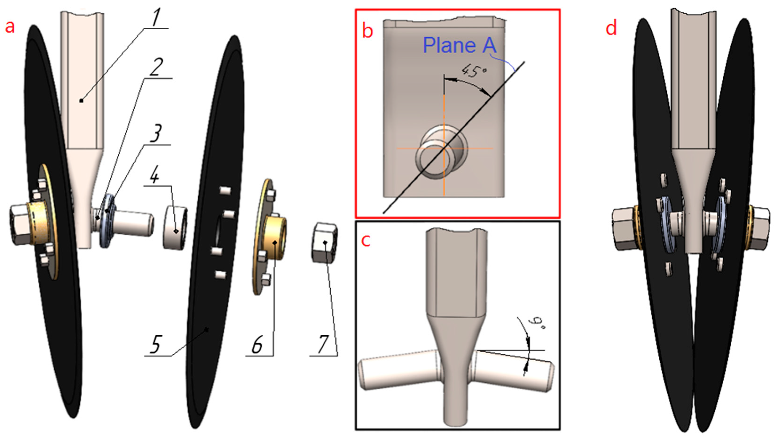
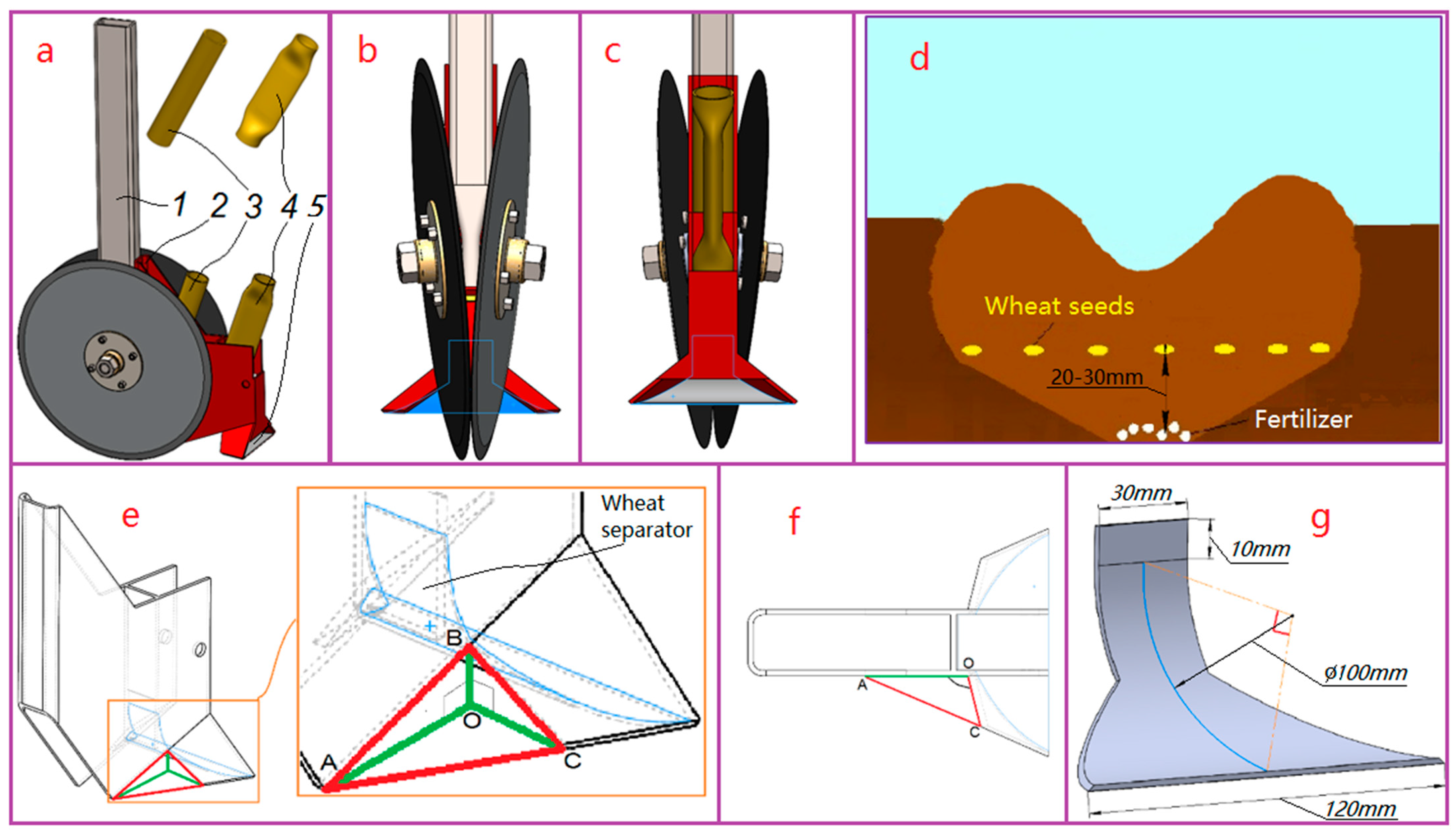
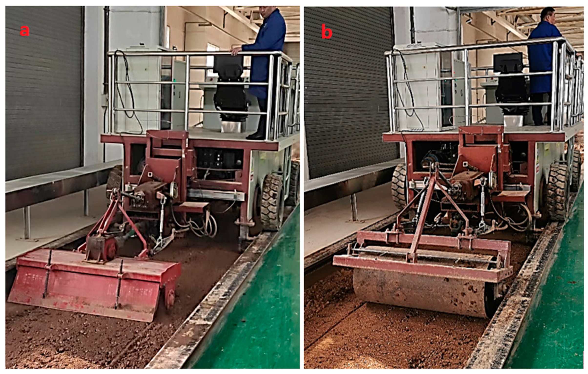
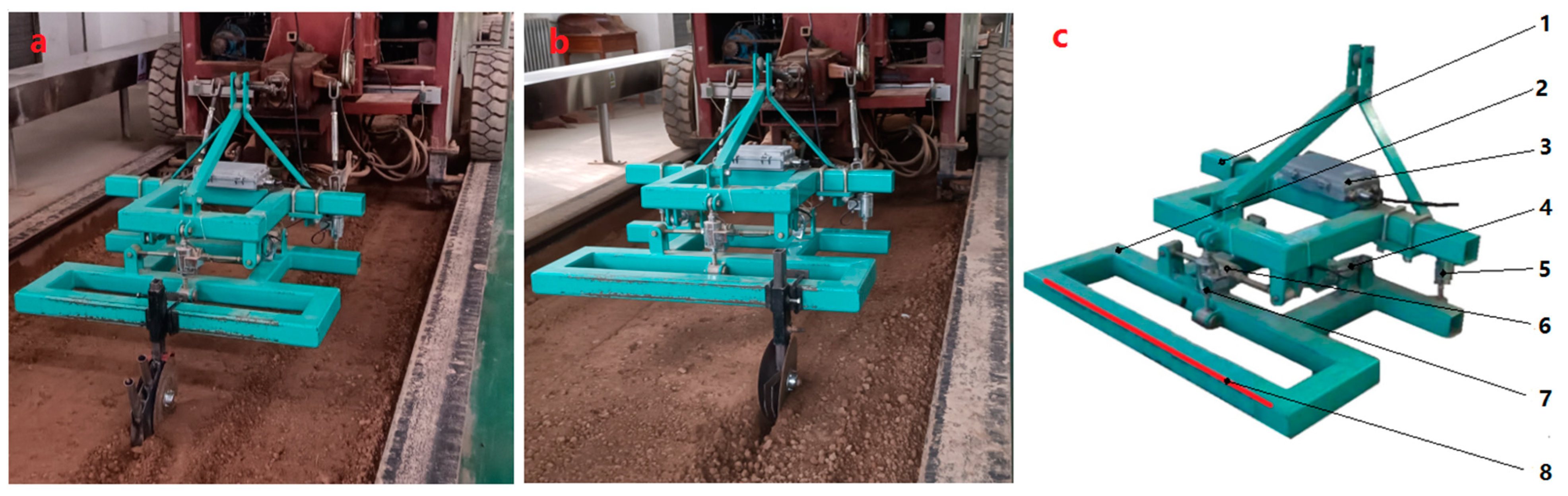
2.1. Design and Parameters of the Base and Designed Disc Colter

A new double-disc colter was designed on the base of the double-disc colter with matching centers (Figure 1). The base double-disc colter consisted of a rectangular post (1), post bolts (2), rubber washers (3), bearings (4), discs (5), hubs (6), and nuts (7) (Figure 1a). The length, width, and thickness of the rectangular post were 400 mm, 50 mm, and 30 mm, respectively, and one side of the rectangular post was deformed to weld the post bolts at 9 degrees toward the front side at 45 degrees (Figure 1b,c). The diameter of the disc was 280 mm. The tilt of the tine bolts allows the discs to assume a forward tilt position to cut the soil and move soil particles from the center to the sides (Figure 1d). The disc was connected to the disc hub, where the bearing allowed it to rotate freely around its axis. The bearing was mounted on the post bolt, and its position was limited by the rubber washer on one side and nuts on the other.
The designed double disc colter consists of a base double disc colter (1), wing frame (2), fertilizer tube (3), and wheat seed tube (4) (Figure 2a–c). A new double-disc colter is designed for simultaneously applying granular fertilizers deeper than the wheat seeds level applied to the band (Figure 2d). The expected distance between the granular fertilizer and wheat seed layers varies between 20 and 30 mm. Because there is a space on the bottom of the double disc colter does not deform the soil. The triangular pyramid shape of the wing frame orifice into which the soil enters is shown in Figure 2e. The ∠AOB and ∠BOC angles are 90 degrees. The inclination of the right and left wings relative to the soil surface depends on the ∠OBC angle, which is 45 degrees. The ∠AOC angle depends on the ∠ABC angle. If the ∠AOC angle is less than 90 degrees, there is a high probability that the wing frame orifice will be blocked by plant stalks or stones. In this design, the ∠ABC angle is also 90 degrees, so ∠AOC is 105 degrees (Figure 2f). Accordingly, the edge of the BC is not perpendicular to the tillage direction. In addition, the BC edges of the right and left wings are beveled at an angle of 45 degrees.
In this design, the plant stalks met along the double disc colter path will slide down along the sharp BC edge or will be cut, and stones bigger than the wing frame orifice will slide down. According to these limitations, the AB dimension is considered a single factor influencing the ΔBOC triangle dimensions, and in this research was 60 mm based on preliminary research. If the ΔBOC triangle is smaller than optimal, the wheat seedbed will not be plain or compacted. Conversely, the orifice will be blocked if the ΔBOC triangle is larger than optimal. A blockage of the orifice is much more problematic than if the carved soil area remains uncovered. This is because a blockage of the orifice can block the granular fertilizer tube and delay the application of the granular fertilizers. The wheat separator is connected to the wing frame (Figure 2g).

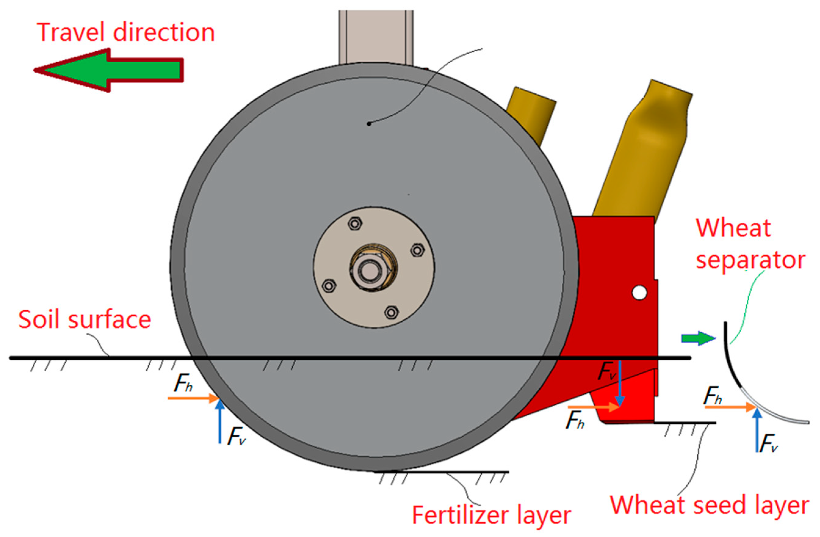
2.2. Analysis of the Vertical and Horizontal Forces Acting on the Designed Double Disc Colter

The specific draught of agricultural tools depends on factors such as soil type and condition, tilling speed, soil friction characteristics, shape, depth of tilling, and types of attachments [37,38]. The directions of the horizontal and vertical forces were studied to determine the effect of the new double-disc colter design, which was compared to the base double-disc colter (Figure 3). During the operation, first of all, the double-disc colter cut the soil. Left and right discs cut the soil layer to a certain depth and spread the soil in a transverse direction, forming a groove that causes rolling resistance [39,40]. Therefore, the disc’s horizontal force F h opposes the direction of travel, and the disc’s vertical force F v directs upward. Second, the soil part spread in a transverse direction covers the formed groove through the wing frame orifice and is then compacted by a wheat separator. The wheat separator also causes soil resistance, and the horizontal force F h opposes the direction of travel, and the vertical force F v directs upward. Third, the soil part spread in a transverse direction also interacts with the wing frame. How soil particles are directed by the size and shape of the tiller is well-studied in the literature [41,42,43]. The direction of the wing frame’s horizontal force F h opposes the direction of travel. The direction of the vertical force F v of the wing frame directs downward. Because the wing frame inclination is less than 67.5 degrees, that is the critical angle ( α c ) [44,45]. This critical angle for a wing frame is expressed as:
α c = π 2 δ
where α c is the critical stand angle, and δ is the angle of soil–stand friction ( δ = 22.5 ° ) .
Using a volumetric dynamometer unit, the horizontal and vertical forces of the base and the designed double disc colters are examined in the soil bin.

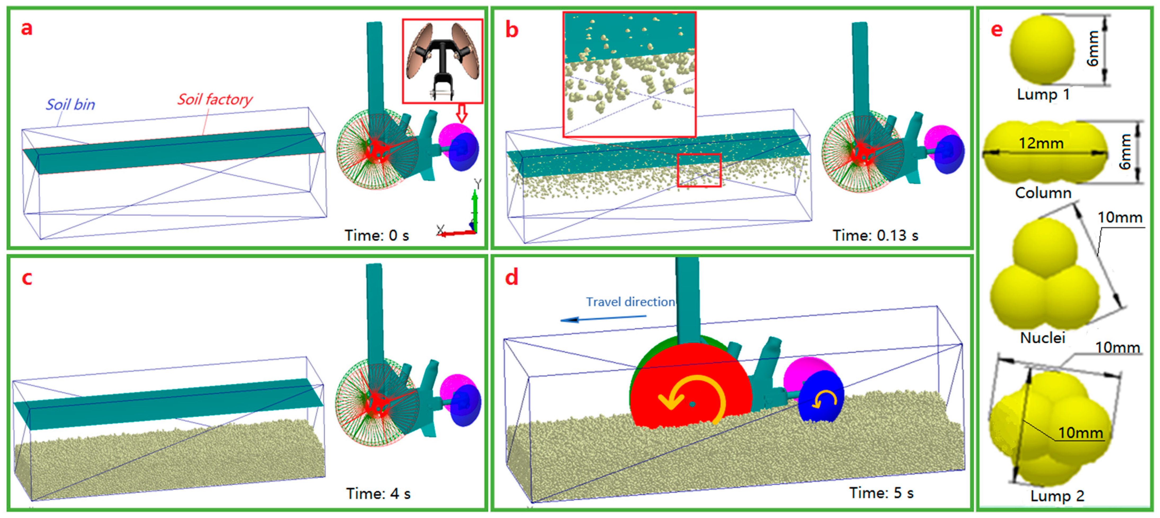
2.3. The Simulation Procedure for the Soil–Soil and Soil–Double Disc Colter Interactions on DEM

The DEM is a suitable tool for modeling the soil–soil and soil–designed double-disc colter interactions [46]. Therefore, in this research, soil, and designed double-disc colter interactions were investigated by tracking soil particle positions as they interacted with the double-disc colter at all stages of the tilling experiment. First of all, to understand why an orifice is added to the wing frame, a simulation experiment was carried out. The AB length was 60 mm. First, a soil bin and factory inside the soil bin were generated. The soil bin’s length, width, and height were 1000 mm, 300 mm, and 500 mm, respectively (Figure 4a). The soil factory was 300 mm off the bottom of the soil bin and is a plane that randomly generates the soil aggregates. The distributed shares of the four soil aggregates were 25%. A new double-disc colter was inserted and placed near the soil bin in the middle, 50 mm above the bottom of the soil bin. The soil-covering discs were set behind the designed double-disc colter to cover the seeds with the soil. The working process of the soil-covering discs is studied in the literature [47]. After setting all the calibrated input parameters of the DEM, soil aggregates began to fall with an initial speed of 0.5 m/s (Figure 4b). Seventy thousand soil aggregates fell into the soil bin in 4 s, and bonds among soil aggregates were active according to the input parameters (Figure 4c). The Hertz-Mindlin with bonding contact model is chosen in this experiment, and the theory is described in the literature [48]. The final total height of the soil inside the soil bin was 150 mm. In the experiment, the designed double-disc colter moved forward at a speed of 0.81 m/s, tilling the soil and deforming the bonds between the soil aggregates (Figure 4d). The soil deformation was examined immediately after the passage of the designed double-disc colter. The simulation target was to ensure the wing frame orifices direct enough soil aggregates inward for compaction with the wheat separator. The designed double disc colter wing orifice results were confirmed by real experiments carried out on an actual soil bin. This research used the soil aggregations Lump1, Column, Nuclei, and Lump 2 to fill the soil bin (Figure 4e) [49].
The input parameters of the soil aggregates and the interactions with the steel used to simulate designed double disc colter interactions with the soil on DEM are shown in Table 1 and Table 2. These interaction properties are calibrated based on the soil particle shape in the literature [12,49,50,51,52,53].

2.4. Preparing the Soil Bin

The experiment in the soil bin was conducted in a 10 m by 2 m area in the College of Mechanical and Electronic Engineering of Northwest A&F University, Xianyang, Shaanxi Province, China. The soil was a loamy clay with a granular structure that developed on parent loess [54]. The initial soil moisture was around 6%. To increase the soil moisture, water was spread gradually on the soil surface and mixed with a rotary tiller (Figure 5a). The moisture content of the soil was measured with a SU-LPC portable soil moisture analyzer produced by Beijing Mengchuangweiye Technology, Ltd. After obtaining the 20% of soil moisture, the soil bin area was compacted with a cylindrical roller (Figure 5b). The length, diameter, and weight of the cylindrical roller were 1.5 m, 0.6 m, and 1000 kg, respectively. The soil was compacted until it stopped hardening. The soil hardness depended on soil depth and was measured every 2.5 cm to 10 cm deep using an SC900 spectrum soil compaction meter produced by Spectrum Technology, Ltd., Bridgend, UK. Soil hardness to 10 cm deep was monitored in this experiment as the double disc colter applying the granular fertilizers and wheat seeds did not exceed 10 cm.

2.5. Measuring the Horizontal and Vertical Forces of the Double Disc Colter

The volumetric dynamometer unit was used in the soil bin experiment to measure the horizontal and vertical forces of the designed and base double disc colters (Figure 6a,b) [55,56,57]. The horizontal and vertical forces were used to compare the designed double disc colter to the base. The TCC-2.1 pulling machine attached the volumetric dynamometer unit (Figure 6c) via a three-point hitch. The TCC-2.1 pulling machine was produced by Heilongjiang Bona Technology, Ltd. in Harbin, China. The double disc colter was mounted to the volumetric dynamometer unit, and the tillage depth was set to 7 cm by adjusting the three-point hitch of the pulling machine. The volumetric dynamometer unit comprised an upper frame and a bottom frame. The three-point hitch was connected to the upper frame via bolts, while the bottom frame was connected to the upper frame via six load sensors used to measure the horizontal and vertical forces. The sum of the left and right horizontal sensor values was taken as the horizontal force value, while the sum of the three vertical sensor values was taken as the vertical force value. When the pulling machine started drawing the volumetric dynamometer unit at a speed of 0.81 m/s, the data from the sensors were transferred to the main computer via the CAN bus system, and the data were saved in an Excel file. The experiment was repeated three times with soil moisture at about 20%. All experiments were conducted in triplicate, and the average of the triplicated experiments was taken as the result. In this research, the speed was constant because, in previous research, the increase in speed increased the draft force [58,59,60].

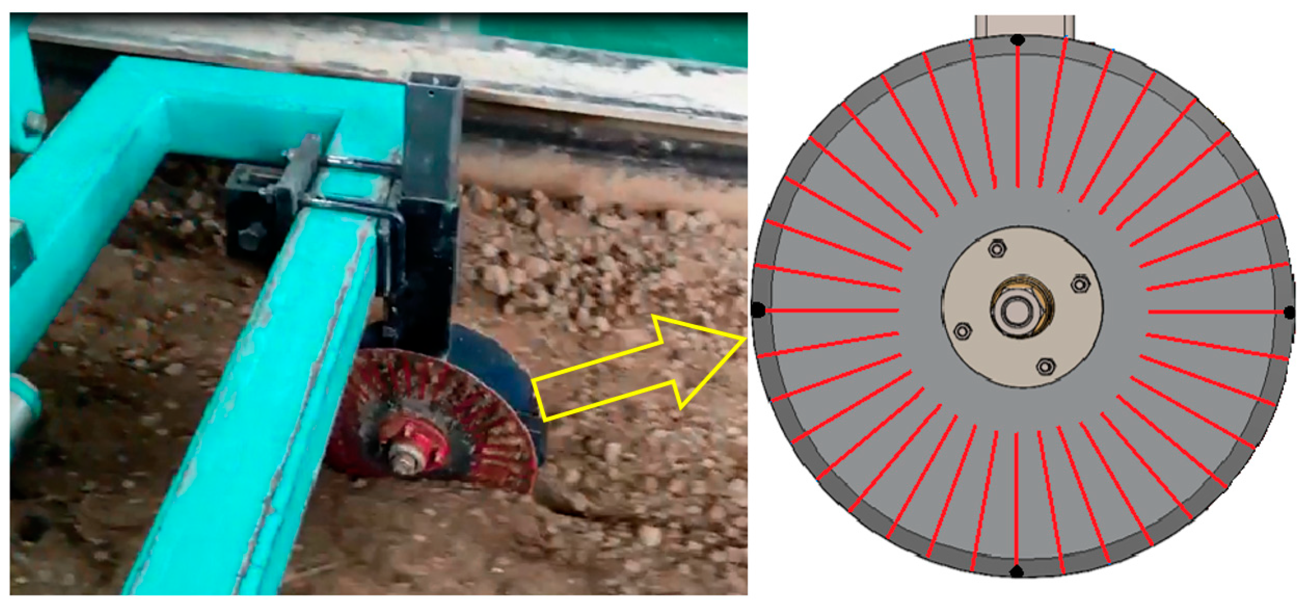
2.6. Determining the Discs’ Free Rotation to Simulate DEM

When double disc colter interacts with the soil, forces of normal soil pressure and friction act on the side faces of the flat disk moving in its plane in the soil, and forces of soil crushing resistance act on the edge of the disk blade. Moreover, it is assumed that discs move in slip mode. The mathematical model of the free-rotating discs with the soil is studied in the literature [61,62,63]. The disc’s free rotation depends on the soil’s physical and mechanical parameters and soil tillage depth. Therefore, discs free rotation was determined experimentally in the soil bin. To count the discs’ free rotation, one side of the base double disc colter was marked (Figure 7).

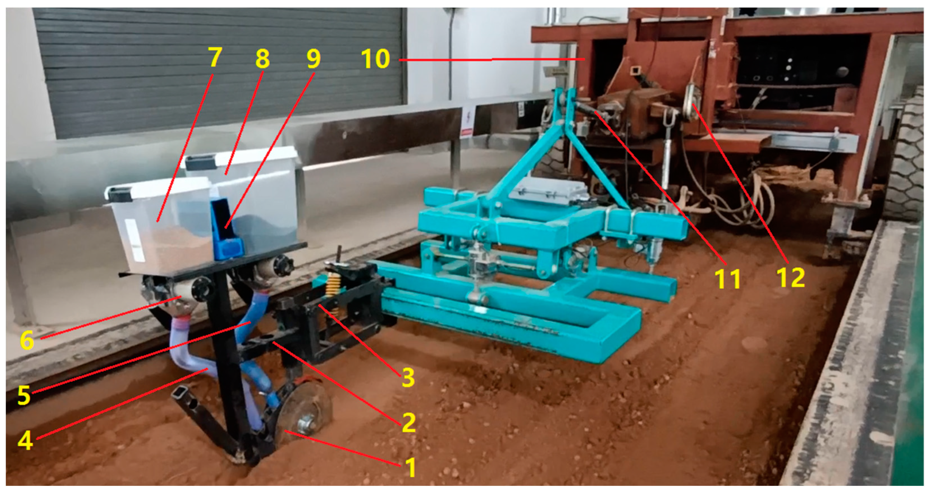
2.7. Determining the Placement of the Wheat Seeds and Granular Fertilizers

A soil bin experiment was conducted with a seeder to determine where granular fertilizers and wheat seeds would fall (Figure 8). The designed double disc colter (1) was set in the seeder frame (2) using the parallel mechanism (3). The parallel mechanism was fixed in one position. Granular fertilizer and wheat seeds were supplied to the double disc colter via the wheat delivery tube (4) and fertilizer delivery tube (5), respectively. Fertilizer and wheat tanks were mounted to the seeder frame. The granular fertilizers and wheat seeds were measured by metering devices (6) at the fertilizer tank (7) and wheat seeds tank (8). The two metering devices were identical and were driven by a DC motor. The DC motors were powered by a 24 V battery (9) and were remote-controlled. The working length and the rotation speed of the metering devices were set to 60 mm and 60 rpm, respectively [64,65]. Therefore, the metering devices can discharge high doses of granular fertilizers and wheat seeds. When high doses of granular fertilizers and wheat seeds are applied, it is easy to identify where the granular fertilizers and wheat seeds fell. The seeder frame was connected to the pulling machine (10) via the three-point hitch (11). The wheat seed level was controlled by adjusting the height controller (12). First, the seeding depth was set to 7 cm. Second, when the pulling machine started pulling the seeder, the metering devices started discharging granular fertilizers and wheat seeds from the tanks to the designed double disc colter through the delivery tubes. Third, the positions of the granular fertilizer and wheat seeds were determined by scraping the soil until reaching the wheat seed and granular fertilizer levels.

3. Results and Discussion

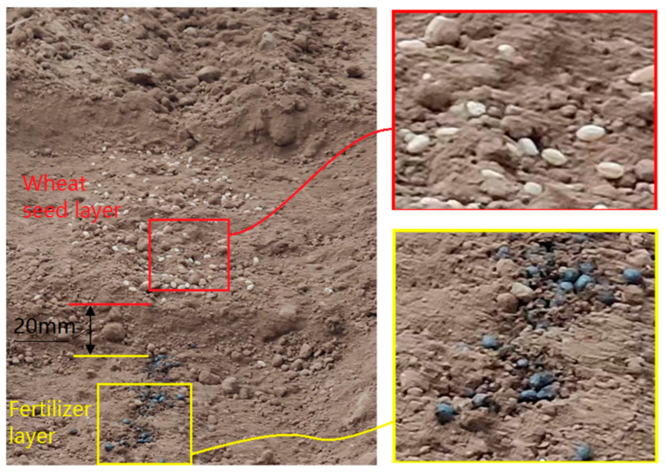
3.1. Results of Placement of the Wheat Seeds and Granular Fertilizers

The results of the placement of the wheat seeds and granular fertilizers provided in the soil bin are shown in Figure 9. The wheat seeds were placed in the horizontal band with the granular fertilizer in a narrow band below the wheat seeds, for which a new double-disk colter was designed. The width of the wheat seeds’ horizontal band was about 120 mm. Determining the position of granular fertilizers was easy due to the hygroscopic properties of absorbing soil moisture. Granular fertilizers and wheat seeds took their positions as expected. The minimum distance between the wheat seed and granular fertilizer layers was 20 mm. The width of the granular fertilizer narrow band was about 20 mm. The thickness of the granular fertilizer layer was about 10 mm.
It should be noted that when distributing wheat seeds along a horizontal band, it is necessary to control the distance between them, which is beyond the scope of this study. Nevertheless, the experiment results show that the 60 mm length of the wing frame orifice was sufficient to cover the layer of granular fertilizer with soil and create a compacted seedbed. Therefore, we consider the compaction of the seed bed to be satisfactory. All wheat seeds lay in one horizontal band.

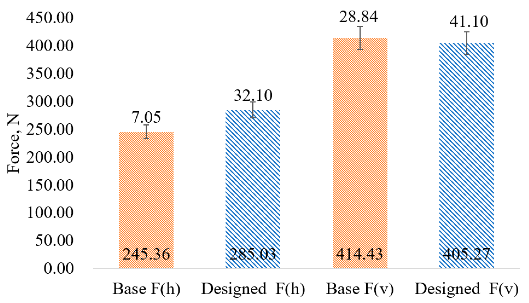
3.2. Results of the Horizontal and Vertical Forces of the Double Disc Colter

The results of the experiment in the soil bin determining the horizontal and vertical forces of the base and designed double disc colters are shown in Figure 10. The horizontal force of the designed and base double disc colters was 285.03 N and 245.36 N, respectively. The effect of the wing frame and the wheat separator directing the soil into the wing frame to cover the fertilizer layer and compacting the soil creating the plain seedbed, was about 40 N. The horizontal force of the designed double disc colter is 14% more than the base double disc colter. However, we consider using a single-designed double disc colter simultaneously applying granular fertilizers and wheat seeds is more efficient than using two base double disc colters separately applying granular fertilizers and wheat seeds. The vertical force of the designed and base double disc colters was 405.27 N and 414.43 N, respectively. This shows that the designed double disc colter requires less vertical force than the base double disc colter by more than 2%. It should be noticed that the vertical forces of the wing frame and wheat separator are contradictory. In this case, when the AB length of the orifice was 60 mm, the vertical force of the wing frame was more than the vertical force of the wheat separator. As a result, the standard deviation of the designed double disc colter was more than the base double disc colter. It is considered that the designed double disc colter is more sensitive to soil hardness fluctuations. These experiments were provided when the soil moisture was about 20 ± 3%. When providing the experiment, the soil hardness was 1050 ± 30 kPa, 950 ± 30 kPa, 850 ± 30 kPa, and 700 ± 30 kPa when the soil depth was 2.5 cm, 5 cm, 7.5 cm, and 10 cm, respectively.

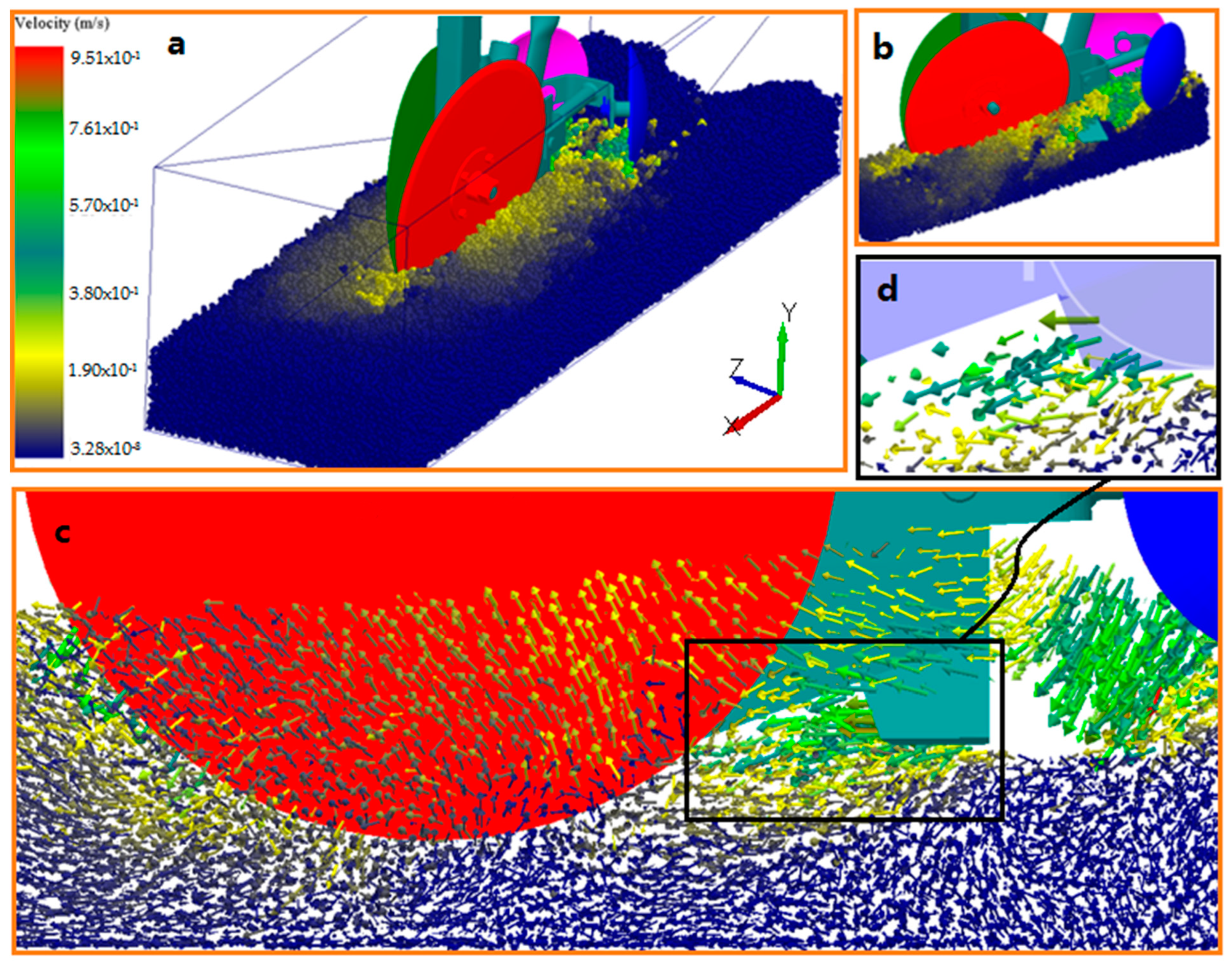
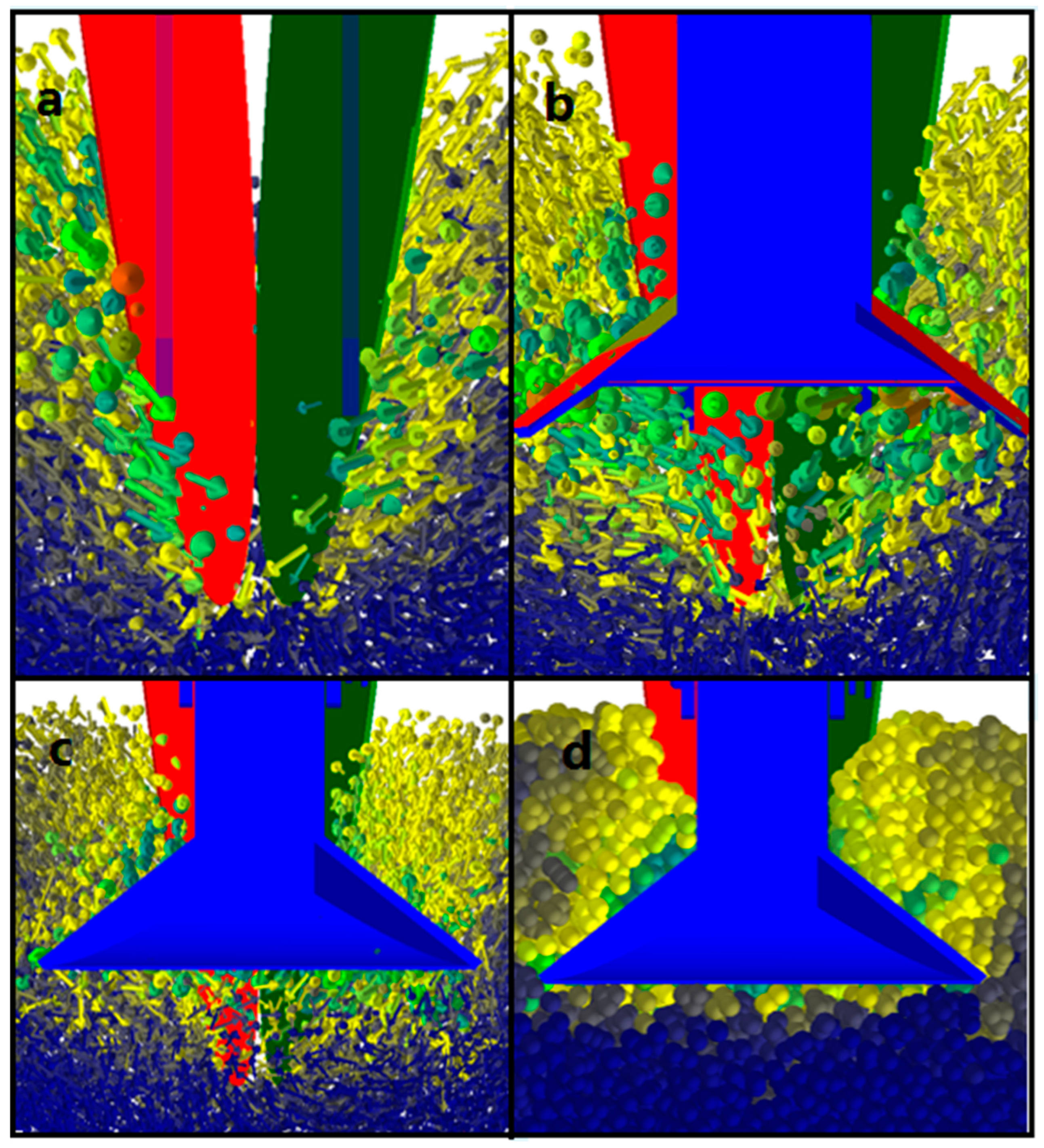
3.3. Simulation Results of the Soil–Soil, and Soil–Designed Double Disc Colter Interactions on DEM

The interactions of the soil particles and double disc colter were simulated on DEM, and the soil velocity and particle moving directions were monitored (Figure 11). The change in the soil particle color represents the soil deformation on the soil surface (Figure 11a). To determine the vertical soil particle deformation, only soil particles close to the designed double disc colter were chosen to be visible (Figure 11b). In the simulation, the double disc colter was rotating at 43 rev/min according to actual experimental results provided in the soil bin. To determine the soil particle moving directions by interacting with the designed double disc colter default form of the soil particles was changed to the vector (Figure 11c). The vector shows the direction of the soil particle movement, and the color of the vector shows the soil particle velocity. The designed double disc colter moving forward through friction shifts the soil particles. At the front side of the disc, the soil particles are shifted to the front downside, and at the back side of the disc, the soil particles are shifted to the front upside. That is because discs are not only moving forward but also rotating. Therefore, the soil particles interacting with the wing frame are shifted front side and then fall, covering the seedbed. The direction of the vectors inside the wing frame is directed front downside covering the granular fertilizer layer (Figure 11d). The simulation of the soil-wheat seeds and soil granular fertilizers interaction was impossible as there were no calibrated parameters.
The soil particles interacting with the designed double disc colter were monitored from the backside, and the moving direction and velocity of the soil particles were demonstrated by colorful vectors (Figure 12). When the double disc colter passes, the soil particles start falling to the middle side (Figure 12a). However, free-filling soil particles are insufficient to cover the granular fertilizer layer. Therefore, soil particles are forced to enter through the wing orifice (Figure 12b). Finally, the entered soil particles are compacted by the wheat separator creating the plain seedbed (Figure 12c,d).

4. Conclusions

A new double-disc colter was designed to simultaneously apply granular fertilizer and wheat seeds at two levels, with the former below the latter, in a 12 cm wide flat seedbed. To apply granular fertilizers deeper than wheat seeds, orifices were made in the wing frame to cover the layer of granular fertilizers, directing the soil towards the middle from both sides. The novelty of the designed double-disc colter lies in the fact that it covers the granular fertilizer layer with soil, compacts the soil, and brings wheat seeds from above. The satisfactory AB length of the wing frame orifice was determined to be 60 mm, verified by carrying out real experiments in a soil bin. The wheat separator compacted the soil, creating an even seedbed and spreading the wheat seeds over a 12 cm wide swath. The designed double disc colter was compared with the base double disc colter to determine the effectiveness of the designed double disc colter. The horizontal force of the designed double disc colter is 14% more than the base double disc colter. However, a single-designed double disc colter is more efficient than two base double disc colters. The behavior of the soil particles interacting with the designed double disc colter is simulated on DEM.

Author Contributions

Conceptualization, A.S. and J.C.; methodology, K.Z.; software, G.L.; validation, G.H., Z.M. and R.I.; formal analysis, N.K.; investigation, A.S.; resources, M.M.; data curation, V.K.; writing—original draft preparation, A.S.; writing—review and editing, Y.C.; visualization, S.Z.; supervision, J.C.; project administration, G.H.; funding acquisition, J.C. and S.Z. All authors have read and agreed to the published version of the manuscript.

Funding

This research was funded by the National Key Research and Development Program of China [grant number 2018YFD0701102], the Shaanxi Key Research and Development Project [grant number 2023-ZDLNY-62], and the Shaanxi Key Research and Development Project [grant number 2022NY-205].

Data Availability Statement

Data will be available on request from the first author, [A.S.].

Conflicts of Interest

The authors declare no conflict of interest.

References

  1. Maraseni, T.; Cockfield, G. Does the adoption of zero tillage reduce greenhouse gas emissions? An assessment for the grains industry in Australia. Agric. Syst. 2011, 104, 451–458. [Google Scholar] [CrossRef]
  2. Yue, K.; Fornara, D.A.; Heděnec, P.; Wu, Q.; Peng, Y.; Peng, X.; Ni, X.; Wu, F.; Peñuelas, J. No tillage decreases GHG emissions with no crop yield tradeoff at the global scale. Soil Tillage Res. 2023, 228, 105643. [Google Scholar] [CrossRef]
  3. Hassan, W.; Li, Y.; Saba, T.; Jabbi, F.; Wang, B.; Cai, A.; Wu, J. Improved and sustainable agroecosystem, food security and environmental resilience through zero tillage with emphasis on soils of temperate and subtropical climate regions: A review. Int. Soil Water Conserv. Res. 2022, 10, 530–545. [Google Scholar] [CrossRef]
  4. Jat, R.K.; Singh, R.G.; Gupta, R.K.; Gill, G.; Chauhan, B.S.; Pooniya, V. Tillage, crop establishment, residue management and herbicide applications for effective weed control in direct seeded rice of eastern Indo–Gangetic Plains of South Asia. Crop Prot. 2019, 123, 12–20. [Google Scholar] [CrossRef]
  5. Rai, N.; Zhang, Y.; Ram, B.G.; Schumacher, L.; Yellavajjala, R.K.; Bajwa, S.; Sun, X. Deep learning applications in precision weed management: A review. Comput. Electron. Agric. 2023, 206, 107698. [Google Scholar] [CrossRef]
  6. Su, W.-H. Crop plant signaling for real-time plant identification in smart farm: A systematic review and new concept in artificial intelligence for automated weed control. Artif. Intell. Agric. 2020, 4, 262–271. [Google Scholar] [CrossRef]
  7. Bu, L.; Chen, C.; Hu, G.; Sugirbay, A.; Sun, H.; Chen, J. Design and evaluation of a robotic apple harvester using optimized picking patterns. Comput. Electron. Agric. 2022, 198, 107092. [Google Scholar] [CrossRef]
  8. Hu, G.; Chen, C.; Chen, J.; Sun, L.; Sugirbay, A.; Chen, Y.; Jin, H.; Zhang, S.; Bu, L. Simplified 4-DOF manipulator for rapid robotic apple harvesting. Comput. Electron. Agric. 2022, 199, 107177. [Google Scholar] [CrossRef]
  9. Zhao, J.; Sugirbay, A.; Chen, Y.; Zhang, S.; Liu, F.; Bu, L.; Wang, Z.; Chen, J. FEM explicit dynamics simulation and NIR hyperspectral reflectance imaging for determination of impact bruises of Lycium barbarum L. Postharvest Biol. Technol. 2019, 155, 102–110. [Google Scholar] [CrossRef]
  10. Ahmad, F.; Weimin, D.; Qishou, D.; Rehim, A.; Jabran, K. Comparative Performance of Various Disc-Type Furrow Openers in No-Till Paddy Field Conditions. Sustainability 2017, 9, 1143. [Google Scholar] [CrossRef]
  11. Portella, J.A.; Capellari, F. Forces on Double Disc Coulters with Different Angles of Attack for a Planter Unit. Sci. Cum Ind. 2018, 6, 7–9. [Google Scholar] [CrossRef]
  12. Chen, Y.; Cheng, Y.; Chen, J.; Zheng, Z.; Hu, C.; Cao, J. Design and Experiment of the Buckwheat Hill-Drop Planter Hole Forming Device. Agriculture 2021, 11, 1085. [Google Scholar] [CrossRef]
  13. Francetto, T.R.; Alonço, A.D.S.; Brandelero, C.; Machado, O.D.d.C.; Veit, A.A.; Carpes, D.P. Disturbance of Ultisol soil based on interactions between furrow openers and coulters for the no-tillage system. Span. J. Agric. Res. 2016, 14, e0208. [Google Scholar] [CrossRef]
  14. Tanbayev, K.; Nukeshev, S.; Sugirbay, A. Performance Evaluation of Tillage Knife Discharge Microchannel. Acta Technol. Agric. 2022, 25, 169–175. [Google Scholar] [CrossRef]
  15. Chaudhuri, D. PM—Power and Machinery: Performance Evaluation of Various Types of Furrow Openers on Seed Drills—A Review. J. Agric. Eng. Res. 2001, 79, 125–137. [Google Scholar] [CrossRef]
  16. Fallahi, S.; Raoufat, M. Row-crop planter attachments in a conservation tillage system: A comparative study. Soil Tillage Res. 2008, 98, 27–34. [Google Scholar] [CrossRef]
  17. Aikins, K.A.; Antille, D.L.; Jensen, T.A.; Blackwell, J. Performance comparison of residue management units of no-tillage sowing systems: A review. Eng. Agric. Environ. Food 2019, 12, 181–190. [Google Scholar] [CrossRef]
  18. Raoufat, M.; Matbooei, A. Row cleaners enhance reduced tillage planting of corn in Iran. Soil Tillage Res. 2007, 93, 152–161. [Google Scholar] [CrossRef]
  19. Altikat, S.; Celik, A. Effects of different no-till seeders and tractor forward speed on the soil physical properties and seed emergence of summer vetch and winter wheat. J. Agric. Sci. 2012, 18, 21–30. [Google Scholar]
  20. Wen, D.; Xu, H.; Xie, L.; He, M.; Hou, H.; Wu, C.; Li, Y.; Zhang, C. Effects of Nitrogen Level during Seed Production on Wheat Seed Vigor and Seedling Establishment at the Transcriptome Level. Int. J. Mol. Sci. 2018, 19, 3417. [Google Scholar] [CrossRef]
  21. Fujii, T.; Hasegawa, H.; Ohyama, T.; Sinegovskaya, V.T. Evaluation of tillage efficiency and power requirements for a deep-placement fertilizer applicator with reverse rotational rotary. Russ. Agric. Sci. 2015, 41, 498–503. [Google Scholar] [CrossRef]
  22. Danilov, A.A.; Gogolev, V.L.; Shaihov, M.K. Рабoчий Орган Сеялки Зернoтукoвoй Стерневoй (Working Body of the Grain-Fertilizer Stubble Seeder); Federal Service for Intellectual Property Patents and Trademarks of the Russian Federation: Moscow, Russia, 2006.
  23. Blackshaw, R.E.; Larney, F.; Lindwall, C.W.; Watson, P.R.; Derksen, D.A. Tillage intensity and crop rotation affect weed community dynamics in a winter wheat cropping system. Can. J. Plant Sci. 2001, 81, 805–813. [Google Scholar] [CrossRef]
  24. Santín-Montanyá, M.; Martín-Lammerding, D.; Zambrana, E.; Tenorio, J.L. Management of weed emergence and weed seed bank in response to different tillage, cropping systems and selected soil properties. Soil Tillage Res. 2016, 161, 38–46. [Google Scholar] [CrossRef]
  25. Altikat, S.; Celik, A.; Gozubuyuk, Z. Effects of various no-till seeders and stubble conditions on sowing performance and seed emergence of common vetch. Soil Tillage Res. 2013, 126, 72–77. [Google Scholar] [CrossRef]
  26. Knochel, D.G.; Flagg, C.; Seastedt, T. Effects of plant competition, seed predation, and nutrient limitation on seedling survivorship of spotted knapweed (Centaurea stoebe). Biol. Invasions 2010, 12, 3771–3784. [Google Scholar] [CrossRef]
  27. Xi, X.; Gu, C.; Shi, Y.; Zhao, Y.; Zhang, Y.; Zhang, Q.; Jin, Y.; Zhang, R. Design and experiment of no-tube seeder for wheat sowing. Soil Tillage Res. 2020, 204, 104724. [Google Scholar] [CrossRef]
  28. Gillet, F. Plant Competition. In Encyclopedia of Ecology; Jørgensen, S.E., Fath, B.D., Eds.; Academic Press: Oxford, UK, 2008; pp. 2783–2793. [Google Scholar]
  29. Wang, B.; Gu, F.; Hu, Z.; Wu, F.; Chen, X.; Luo, W. Analysis and Evaluation of Influencing Factors on Uniform Sowing of Wheat with Wide Seed Belt after Sowing and Soil Throwing Device. Agriculture 2022, 12, 1455. [Google Scholar] [CrossRef]
  30. Ebrahim, I. The soil bed preparation to drill rice in band sowing method. J. Agric. Sci. Mansoura Univ. 2002, 27, 2545–2552. [Google Scholar]
  31. Nukeshev, S.O.; Kakabaev, N.A.; Romanyuk, N.N.; Troyanovskaya, I.P.; Smelik, V.A.; Voinash, S.A. Design and rationale for parametres of the seed-fertilizer seeder coulter for subsoil broadcast seeding. IOP Conf. Ser. Earth Environ. Sci. 2021, 677, 052010. [Google Scholar] [CrossRef]
  32. Nukeshev, S.; Slavov, V.; Kakabayev, N.; Amantayev, M. Mathematical Modelling in 3D of Opener with Scatterer of the Grain-Fertilizer Seeder. Mechanika 2019, 24, 840–844. [Google Scholar] [CrossRef]
  33. Olsen, J.M.; Griepentrog, H.W.; Nielsen, J.; Weiner, J. How Important are Crop Spatial Pattern and Density for Weed Suppression by Spring Wheat? Weed Sci. 2012, 60, 501–509. [Google Scholar] [CrossRef]
  34. Haliniarz, M.; Kapeluszny, J. Assessment of the effect of sowing density on weed infestation and yields of three spring wheat cultivars. Acta Sci. Polonorum. Agric. 2022, 11, 13–25. [Google Scholar]
  35. Nukeshev, S.; Eskhozhin, K.; Karaivanov, D.; Sankibaev, T.; Kakabayev, N. Theoretical and experimental substantiation of the design of an opener for intrasoil broadcast sowing of grain crops. Bulg. J. Agric. Sci. 2016, 22, 862–868. [Google Scholar]
  36. Kem, A.S.; Shevchenko, A.P.; Evchenko, A.V. Movement of seeds in the underweep space of drill coulter in the condition of pneumatic feed. IOP Conf. Ser. Earth Environ. Sci. 2021, 624, 012069. [Google Scholar] [CrossRef]
  37. Odey, S.; Manuwa, S. Design steps of narrow tillage tools for draught reduction and increased soil disruption-a review. Agricultural Engineering International. CIGR E-J. 2016, 18, 91–102. [Google Scholar]
  38. Rustembayev, A.; Eskhozhin, D.; Nukeshev, S.; Zhaksylykova, Z.; Eskhozhin, K. The theoretical rationale for traction effort experienced working part of the cultivator fertilizer. Int. J. Mech. Eng. Technol. 2019, 10, 424–433. [Google Scholar]
  39. Gumarov, G.S.; Konovalov, V.V.; Sarsenov, A.E.; Kubasheva, Z.K.; Rakhimov, A.A. Mathematical modelling of traction resistance of the improved opener of grain seeder. BIO Web Conf. 2020, 17, 00044. [Google Scholar] [CrossRef]
  40. Kokoshin, S.N.; Kirgintsev, B.O.; Tashlanov, V.I. Disc seeder with auto tracking system depth of sowing seeds. J. Phys. Conf. Ser. 2020, 1614, 012051. [Google Scholar] [CrossRef]
  41. Gheres, M.; Tutunaru, L.F.; Ferenc, G.; Deac, T. Optimization of geometric parameters of scarificators for the reduction of the soil—Tool interaction forces. In Proceedings of the International Symposium, ISB-INMA TEH’2019, Agricultural and Mechanical Engineering, Bucharest, Romania, 31 October–1 November 2019. [Google Scholar]
  42. Gheres, M.; Constantin, C. Mathematical Model for Determination of Soil Tillage Resistance Forces. In Proceedings of the International Symposium, ISB-INMA TEH’2018, Agricultural and Mechanical Engineering, Bucharest, Romania, 1–3 November 2018; pp. 229–238. [Google Scholar]
  43. He, C.; Guo, Y.; Guo, X.; Sang, H. A mathematical model for predicting the draft force of shank-type tillage tine in a compacted sandy loam. Soil Tillage Res. 2023, 228, 105642. [Google Scholar] [CrossRef]
  44. Godwin, R.; Spoor, G. Soil failure with narrow tines. J. Agric. Eng. Res. 1977, 22, 213–228. [Google Scholar] [CrossRef]
  45. Li, B.; Chen, Y.; Chen, J. Modeling soil–claw interaction using the discrete element method (DEM). Soil Tillage Res. 2016, 158, 177–185. [Google Scholar] [CrossRef]
  46. Cundall, P.A.; Strack, O.D.L. A discrete numerical model for granular assemblies. Géotechnique 1979, 29, 47–65. [Google Scholar] [CrossRef]
  47. Geng, Y.; Wang, X.; Zhong, X.; Zhang, X.; Chen, K.; Wei, Z.; Lu, Q.; Cheng, X.; Wei, M. Design and Optimization of a Soil-Covering Device for a Corn No-Till Planter. Agriculture 2022, 12, 1218. [Google Scholar] [CrossRef]
  48. Zhou, H.; Chen, Y.; Sadek, M.A. Modelling soil–seed contact using the Discrete Element Method (DEM). Biosyst. Eng. 2014, 121, 56–66. [Google Scholar] [CrossRef]
  49. Hang, C.; Gao, X.; Yuan, M.; Huang, Y.; Zhu, R. Discrete element simulations and experiments of soil disturbance as affected by the tine spacing of subsoiler. Biosyst. Eng. 2018, 168, 73–82. [Google Scholar] [CrossRef]
  50. Bo, L.; Fanyi, L.; Junying, M.; Jun, C.; Wenting, H. Distinct element method analysis and field experiment of soil resistance applied on the subsoiler. Int. J. Agric. Biol. Eng. 2014, 7, 54–59. [Google Scholar]
  51. Sugirbay, A.; Hu, G.R.; Chen, J.; Mustafin, Z.; Muratkhan, M.; Iskakov, R.; Mukhamed, B. A Study on the Calibration of Wheat Seed Interaction Properties Based on the Discrete Element Method. Agriculture 2022, 12, 1497. [Google Scholar] [CrossRef]
  52. Patwa, A.; Ambrose, R.K.; Casada, M. Discrete element method as an approach to model the wheat milling process. Powder Technol. 2016, 302, 350–356. [Google Scholar] [CrossRef]
  53. Adilet, S.; Zhao, J.; Sayakhat, N.; Chen, J.; Nikolay, Z.; Bu, L.; Sugirbayeva, Z.; Hu, G.; Marat, M.; Wang, Z. Calibration Strategy to Determine the Interaction Properties of Fertilizer Particles Using Two Laboratory Tests and DEM. Agriculture 2021, 11, 592. [Google Scholar] [CrossRef]
  54. Huang, Y.; Hang, C.; Yuan, M.; Wang, B.; Zhu, R. Discrete element simulation and experiment on disturbance behavior of subsoiling. Trans. Chin. Soc. Agric. Mach. 2016, 47, 70–78. [Google Scholar]
  55. Gnusov, M.A.; Lysych, M.N.; Druchinin, D.Y. Volumetric dynamometer units for laboratory and field testing of tillage equipment. J. Phys. Conf. Ser. 2021, 1889, 052047. [Google Scholar] [CrossRef]
  56. Odey, S.O.; Manuwa, S.I.; Ewetumo, T. Instrumentation Assembly for Measuring Draughts of Subsoilers in Outdoor Soil Bin Facility. Int. J. Res. Eng. Sci. 2018, 6, 1–10. [Google Scholar]
  57. Roca, J.; Comellas, M.; Pijuan, J.; Nogués, M. Development of an easily adaptable three-point hitch dynamometer for agricultural tractors. Analysis of the disruptive effects on the measurements. Soil Tillage Res. 2019, 194, 104323. [Google Scholar] [CrossRef]
  58. Sadek, M.A.; Chen, Y.; Zeng, Z. Draft force prediction for a high-speed disc implement using discrete element modelling. Biosyst. Eng. 2021, 202, 133–141. [Google Scholar] [CrossRef]
  59. McLaughlin, N.B.; Campbell, A.J.; Owen, G.T. Performance of hoe and triple disc furrow openers on no-till grain drills in a fine sandy loam soil. Soil Tillage Res. 2019, 195, 104373. [Google Scholar] [CrossRef]
  60. Barr, J.B.; Desbiolles, J.M.; Fielke, J.M.; Ucgul, M. Development and field evaluation of a high-speed no–till seeding system. Soil Tillage Res. 2019, 194, 104337. [Google Scholar] [CrossRef]
  61. Akimov, A.; Konstantinov, Y.; Medvedev, V.; Mishin, P.; Volkhonov, M.; Lekomtsev, P.; Obolensky, N.; Yunusov, G. An approximating mathematical model of interaction between a freely rotating disk and soil. East. Eur. J. Enterp. Technol. 2018, 6, 17–27. [Google Scholar] [CrossRef]
  62. Nalavade, P.P.; Salokhe, V.M.; Niyamapa, T.; Soni, P. Performance of Free Rolling and Powered Tillage Discs. Soil Tillage Res. 2010, 109, 87–93. [Google Scholar] [CrossRef]
  63. Nalavade, P.P.; Soni, P.; Salokhe, V.; Niyamapa, T. Comparative Performance of Standard, Notched and Spiral-notched Tillage Discs. Int. Agric. Eng. J. 2011, 20, 18–26. [Google Scholar]
  64. Sugirbay, A.; Zhao, J.; Nukeshev, S.; Chen, J. Determination of pin-roller parameters and evaluation of the uniformity of granular fertilizer application metering devices in precision farming. Comput. Electron. Agric. 2020, 179, 105835. [Google Scholar] [CrossRef]
  65. Adilet, S.; Zhao, K.; Liu, G.; Sayakhat, N.; Jun, C.; Hu, G.; Bu, L.; Chen, Y.; Jin, H.; Zhang, S.; et al. Investigation of the pin-roller metering device and tube effect for wheat seeds and granular fertilizers based on DEM. Int. J. Agric. Biol. Eng. 2023, 16, 103–114. [Google Scholar] [CrossRef]
Figure 1. Base double disc colter parts and parameters: (a). Front view; 1. Rectangular post; 2. Post bolt; 3. Rubber washer; 4. Bearing; 5. Disc; 6. Disc hub; 7. Nut; (b). Left view of the stand; (c). Perpendicular view to plane A; (d). Back view.
Agriculture 13 01102 g001
Figure 2. Designed colter parts and parameters: (a). Designed colter parts: base disc colter (1), wing frame (2), fertilizer tube (3), wheat seed tube (4), and wheat separator (5); (b). Front view of the designed colter; (c). Back view of the designed colter; (d). The positions of the fertilizers and wheat seeds in the soil applied with the designed colter; (e). Wing frame orifice parameters; (f). Top view of the wing frame; (g). Wheat separator parameters.
Agriculture 13 01102 g002
Figure 3. Directions for influencing horizontal and vertical forces on the designed double disc colter interacting with the soil.
Agriculture 13 01102 g003
Figure 4. Interactions between the designed double disc colter and soil aggregates based on the DEM: (a). assembling the soil bin with the soil factory and placing the new double disc colter near the soil bin; (b). Filling the soil bin with soil aggregates; (c). Soil bin filled with soil aggregates; (d). Penetration of the new double-disc colter into the soil bin and determination of soil deformation; (e). The dimensions of the generated soil aggregations.
Agriculture 13 01102 g004
Figure 5. Preparing the soil bin: (a). Mixing the soil with a rotary tiller; (b). Compacting the soil with a cylindrical roller.
Agriculture 13 01102 g005
Figure 6. Measuring horizontal and vertical forces with a volumetric dynamometer unit: (a). Testing designed double disc colter; (b). Testing base double disc colter; (c). Volumetric dynamometer unit parts; 1. Upper frame; 2. Bottom frame; 3. CAN bus system; 4. Horizontal right load sensor; 5. Vertical right load sensor; 6. Lateral load sensor; 7. Back vertical load sensor; 8. A place to mount colters.
Agriculture 13 01102 g006
Figure 7. Counting the free rotation of the base double disc colter.
Agriculture 13 01102 g007
Figure 8. Determining the applied position of the granular fertilizers and wheat seeds: 1. Designed double disc colter; 2. Seeder frame; 3. Parallel mechanism; 4. Wheat delivery tube; 5. Granular fertilizer delivery tube; 6. Metering device; 7. Wheat tank; 8. Fertilizer tank; 9. 24 V battery; 10. Pulling machine; 11. Three-point hitch; 12. Height controller.
Agriculture 13 01102 g008
Figure 9. Placement of the wheat seeds to the horizontal band with the granular fertilizer in a narrow band below the wheat seeds.
Agriculture 13 01102 g009
Figure 10. Horizontal and vertical forces of the base and designed double disc colters.
Agriculture 13 01102 g010
Figure 11. The soil–soil and soil–designed double disc colter interactions on DEM: (a). Soil deformation; (b). Soil particles interact with the designed double disc colter; (c). Soil particle velocity and moving directions through friction; (d). Soil particles’ moving direction inside the wing frame.
Agriculture 13 01102 g011
Figure 12. Monitoring the soil particle position from the backside: (a). Soil particles are falling into the free space; (b). Soil particles enter through the wing orifice; (c). Compacted soil particles employing wheat separator; (d). The default view of the compacted soil particles.
Agriculture 13 01102 g012
Table 1. Input parameters from primary literature for DEM modeling.
Input PropertyValueRelated Investigations
Soil density (kg m−3)1346[49]
Poisson’s ratio of the soil aggregates0.4
Shear modulus of the soil aggregates, (Pa)1 × 10⁶
Soil-soil restitution coefficient0.2
Soil-steel restitution coefficient0.3
The soil-soil static friction coefficient0.4
The soil-soil rolling friction coefficient0.3
The soil-steel static friction coefficient0.5
The soil-steel rolling friction coefficient0.05
Steel density, (kg m−3)7850[12,49,50,51,52,53]
Poisson’s ratio of steel0.3
Shear modulus of steel, (Pa)8.23 × 10¹⁰
Table 2. Bonding parameters of the soil aggregates [49].
Input PropertyValue
Normal stiffness per unit area (N m−1)2,400,000
Shear stiffness per unit area (N m−1)1,700,000
Critical normal stress (Pa)235,000
Critical shear stress (Pa)186,000
Start time (s)4
Bonded disc radius (mm)3.5
Disclaimer/Publisher’s Note: The statements, opinions and data contained in all publications are solely those of the individual author(s) and contributor(s) and not of MDPI and/or the editor(s). MDPI and/or the editor(s) disclaim responsibility for any injury to people or property resulting from any ideas, methods, instructions or products referred to in the content.

