Article

Design and Experiment of Lightweight Dual-Mode Automatic Variable-Rate Fertilization Device and Control System

College of Engineering and Technology, Southwest University, Chongqing 400715, China
*
Author to whom correspondence should be addressed.
Agriculture 2023, 13(6), 1138; https://doi.org/10.3390/agriculture13061138
Submission received: 27 April 2023 / Revised: 21 May 2023 / Accepted: 27 May 2023 / Published: 29 May 2023
(This article belongs to the Special Issue Agricultural Machinery Design and Agricultural Engineering)

Abstract

:
China’s agricultural facilities are developing rapidly and are mainly operated through household contracting. Due to a lack of suitable variable-rate fertilization devices, manual and blind fertilization still widely exists, resulting in fertilizer waste and environmental pollution. Meanwhile, existing fertilization devices cannot simultaneously meet the needs of different fertilization methods for crop cultivation, increasing the cost of mechanized fertilization. This study developed a lightweight dual-mode automatic variable-rate fertilization device and control system for strip fertilization and spreading fertilization. The least squares method was used to analyze the amount of fertilizer discharged per second at different volumes and rotational speeds of the fertilization device. The quadratic polynomial model fits well, with determination coefficients greater than 0.99. The automatic variable strip fertilization and spreading fertilization control models were established. Experiments with strip fertilization and spreading fertilization were carried out. The results of strip fertilization experiments show that the maximum relative error ( R e ) for granular nitrogen fertilizer (NF) was 6.81%, compound fertilizer (CF) was 6.2%, organic compound fertilizer (OCF) was 6.83%, and the maximum coefficient of variation ( C v ) of uniformity was 8.91%. The results of spreading fertilization experiments show that the maximum R e of granular NF was 7.31%, granular CF was 6.76%, granular OCF was 7.43%, the C v of lateral uniformity was 9.88%, and the C v of total uniformity was 14.17%. The developed fertilization device and control system can meet the needs of different fertilization amounts, types, and methods for facility crop cultivation at different stages. This study’s results can provide a theoretical basis and technical support for designing and optimizing multifunctional precision variable-rate fertilization devices and control systems.

1. Introduction

Chemical fertilizers can improve crop yield and quality [1]. However, excessive use will lead to water eutrophication, soil acidification, accumulation of heavy metals, increased pests, and other problems [2,3]. Reducing the application of chemical fertilizers and increasing the application of organic fertilizers can promote the sustainable production of crops [4,5]. Nowadays, the mechanization and automation of crop production is an inevitable trend in China [6], and automatic fertilization is one of the essential links. However, China’s agricultural facilities have a large planting area and high yield, but manual fertilization is still prevalent due to a lack of suitable automatic variable-rate fertilization equipment. This increases production costs and causes insufficient or excessive fertilization, resulting in environmental pollution, and the yield and quality of crops cannot be guaranteed [7]. Therefore, it is important to develop an automatic variable-rate fertilization device for facility agriculture in China.
In recent years, many researchers have focused on inter-row strip fertilization devices, and one of the most widely used is the grooved wheel fertilization device [8]. The changes in the working length and speed of the grooved wheel significantly impact fertilization performance [9]. Fertilization performance can be improved by optimizing the fertilization control sequence model based on the differential evolution (DE) algorithm to obtain the optimal opening and rotation speed combination. At a target fertilization rate of 944.92 g/min, the fertilization uniformity’s coefficient of variation (CV) was the smallest when the control sequence was 18.3 r/min and 25 mm [10]. Optimizing the gap and opening length range between the spiral blade and the discharge chamber through EDEM software and using the tent mapping bat algorithm tuning (TBA) to tune the PID controller parameters can improve the fertilization rate control system’s accuracy and response speed. However, it does not affect the uniformity of fertilization [11]. The grooved wheel fertilization device with spiral teeth can improve fertilizer discharge performance, and a lower coefficient of variation and fracture rate can be obtained when the spiral angle is 47.5° [12].
In addition to the grooved wheel fertilization device, inter-row fertilizer applicators based on other structures have also been investigated and reported [13]. A fertilizer apparatus utilizing arc gears and the discrete element method was used to determine the optimum structural parameters to improve fertilization accuracy and uniformity [14]. A pin-roller structure was used as a variable-rate fertilizer metering device, and the uniformity of fertilizer discharge was 10.36% when its speed was low [15]. A vertical variable cavity organic fertilizer and composite fertilizer device were designed to meet the requirements of tobacco cultivation. When the width of the fertilization opening was greater than 18.4 mm, more uniform and stable fertilization could be achieved [16].
Due to the different approaches to fertilizing crops, many research studies on spreading fertilization devices have been conducted. The air-blown fertilizer spreader was one of the main researched devices for spreading fertilization [17,18]. A variable rate pneumatic fertilizer applicator triggered by RFID for granular fertilizer used in oil palm plantations can apply fertilizer within a target area of 4–12 m on both sides of the machine path. However, it takes two to three seconds to respond to changes in application rate [19]. The rotation speed and baffle type significantly impact the spreading uniformity of variable pneumatic fertilizer applicators. When the rotation speed was about 30 r/min, the coefficient of variation for the spreading uniformity was better than other rotation speeds [20]. The centralized airflow distribution method can reduce the airflow coefficient of variation for centralized pneumatic fertilization devices. When the rotation speed of the fertilizer shaft is 20 r/min, the maximum coefficient of variation for consistency of fertilization in different rows is 1.49%. When the target fertilization rate was 20, 30, and 40 kg/667 m2, the average relative error of fertilization rate in the field test was 3.53% [21].
In addition to the above-mentioned air-blown fertilizer spreader, another critical type of research structure is the centrifugal fertilizer spreader [22,23]. The optimal parameters were obtained by analyzing the relationship between the distribution of fertilizer particles and the operational parameters of the centrifugal fertilizer applicator, and the average coefficient of variation of the effective fertilization area was 16.74% [24]. A centrifugal fertilizer spreader was used for rape undersowing rice on a crawler combine harvester, and the coefficient of fertilizer lateral distribution variation in simulation tests and bench tests was 13.1% and 14.6% [25]. However, the existing fertilization devices cannot perform automatic variable-rate fertilization or have a small range of variable-rate fertilization. It cannot meet the requirements for a large amount of basal fertilizer application in the early stage of crop planting and a small amount of top-dressing fertilizer application in the later stage. In addition, these fertilization devices have a single function and cannot simultaneously meet the needs of strip fertilization and spreading fertilization for facility agriculture in China.
According to different fertilization amount requirements, types, and methods in different periods of facility agricultural crop planting in China, a lightweight dual-mode automatic variable-rate fertilization device was designed, and an automatic control model of precise variable-rate strip fertilization and spreading fertilization was established to allow for variable-rate strip fertilization and spreading fertilization of different granular fertilizers. Tests were carried out with granular nitrogen fertilizers, compound fertilizers, and organic compound fertilizers to evaluate the accuracy and uniformity of the strip fertilization and spreading fertilization of the proposed fertilization device and control system. This study aims to solve the problem of single fertilization function, small adaptation range, and poor uniformity of variable-rate fertilization in traditional fertilization devices, thereby improving the efficiency and accuracy of fertilization and achieving precise fertilization of crops at different stages. The research can provide a reference for designing and optimizing multifunctional variable-rate fertilization devices and control systems.

2. Materials and Methods
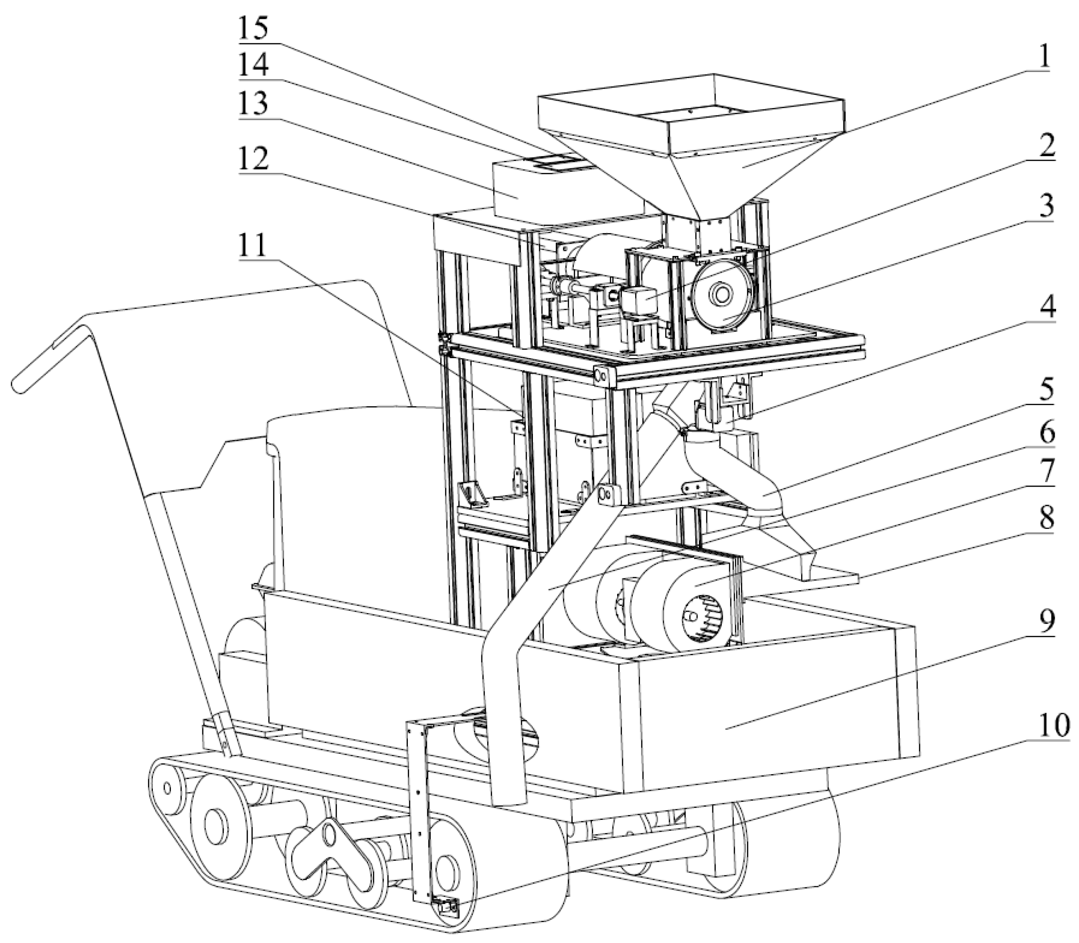
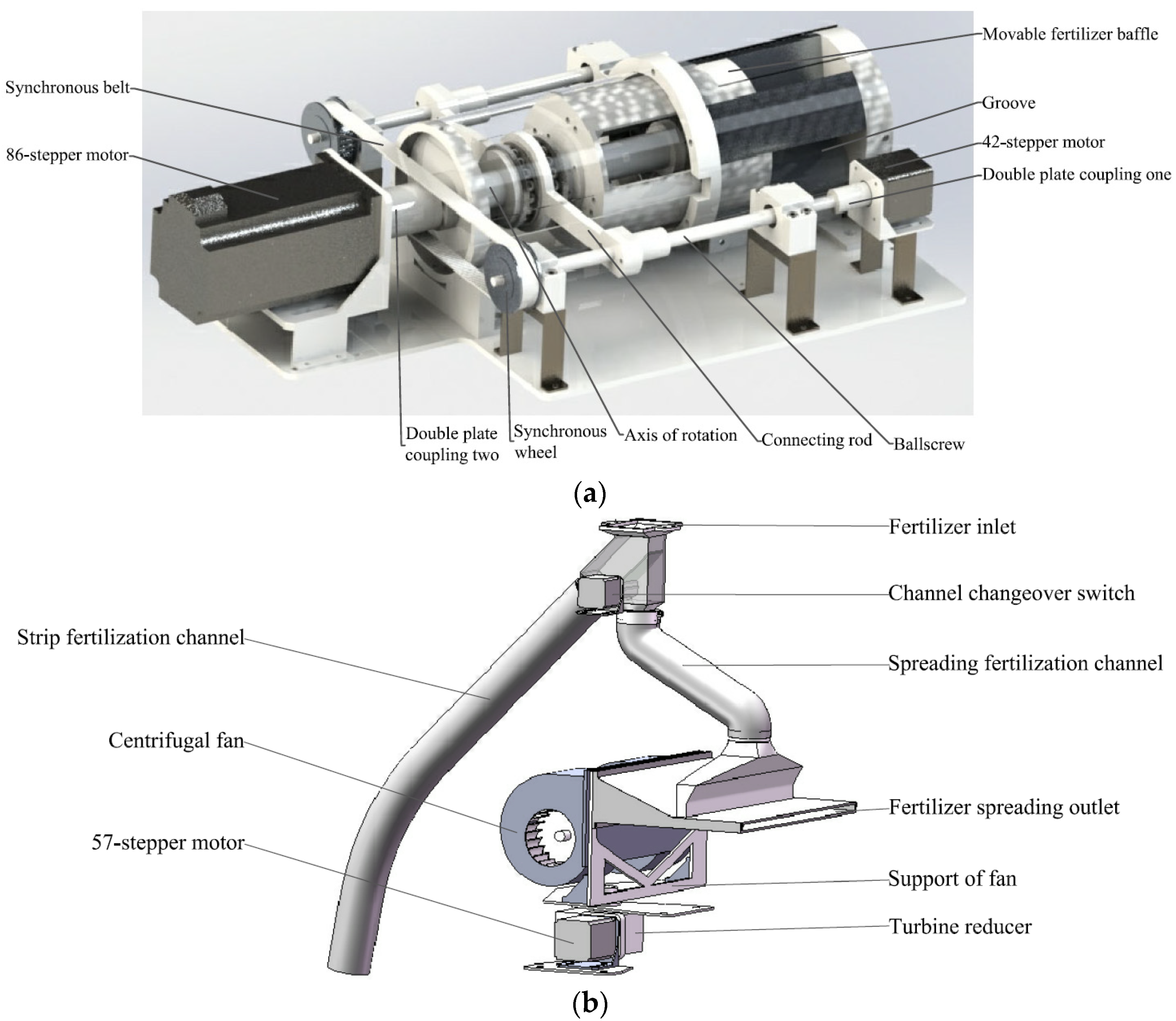
2.1. Overall Design

The amount and type of fertilizer required to differ at the different stages of crop planting in facility agriculture (such as tomatoes and cucumbers). Before planting crops, applying a large amount of organic fertilizer as the base fertilizer is often necessary, using the method of spreading fertilization. During the crop growth stage, it is necessary to apply a small number of chemical fertilizers multiple times using the technique of inter-row fertilization. For example, it is necessary to apply organic fertilizer as the essential fertilizer before planting tomatoes and cucumbers, with fertilization rates of about 9–10.5 kg/m2 and 3.7–4.5 kg/m2, respectively. Top-dressing is required at different growth stages of tomatoes and cucumbers, and the amount of nitrogen or compound fertilizer applied to tomatoes is about 0.018–0.045 kg/m2 each time. The application amount for cucumber is about 0.022–0.03 kg/m2 each time [26].
According to crops’ different fertilizer requirements and fertilization methods at different growth stages, a lightweight dual-mode automatic variable-rate fertilization device has been designed for strip fertilization and spreading fertilization. As shown in Figure 1, the overall structure of the device is mainly composed of a material box, a 42-stepper motor, an outer groove wheel fertilizing structure, a changeover switch, a spreading fertilization channel, a strip fertilization channel, two lidar sensors, a centrifugal fan, a crawler car, a Hall sensor, three batteries, an 86-stepper motor, a control box, a 4 × 4 matrix keyboard, and an LCD screen. The designed volume of the material box is 21,258.3 cm3.

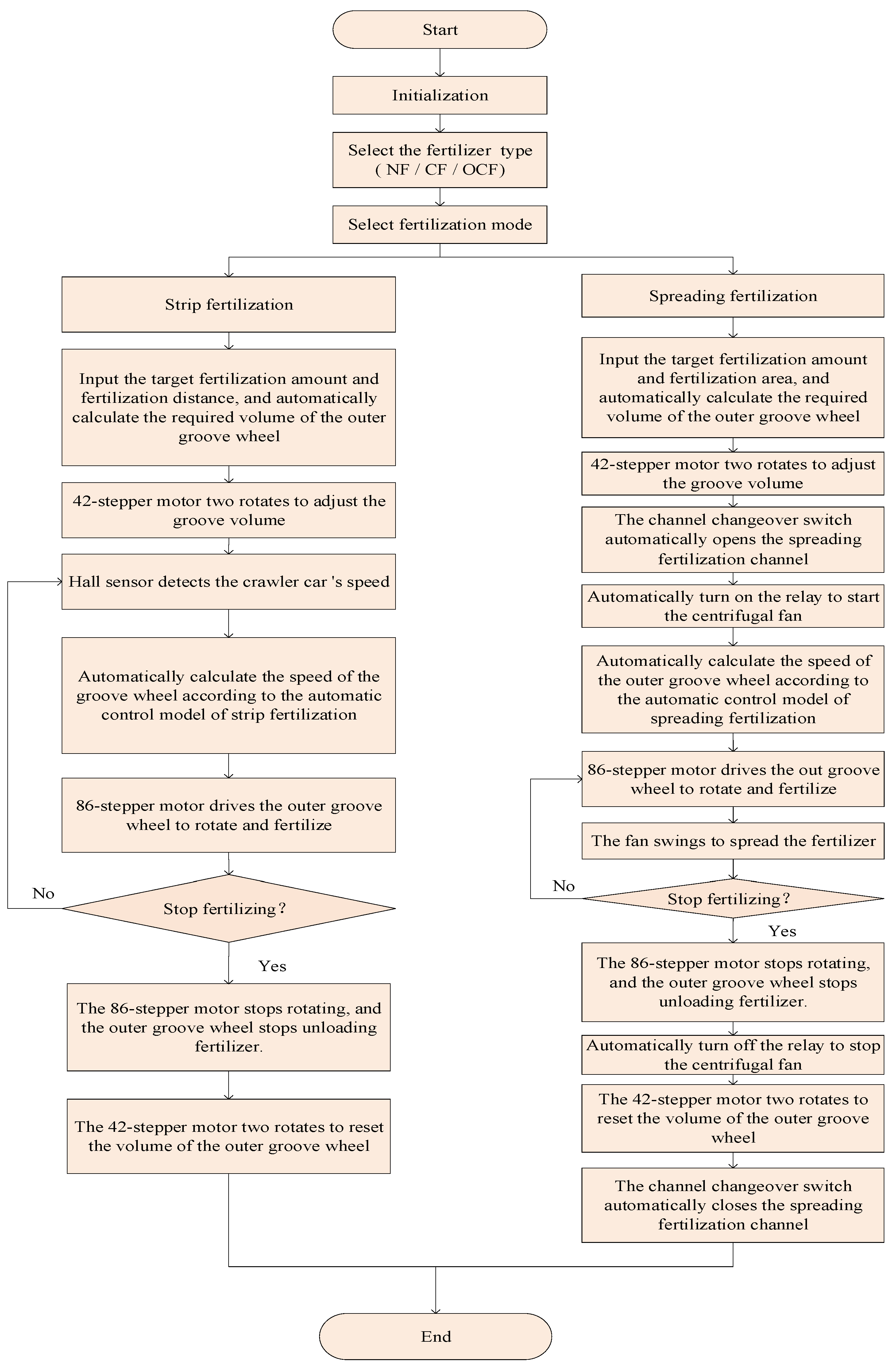
2.2. Working Principle

The main working structure of the dual-mode automatic variable-rate fertilization device is the double variable-rate outer groove wheel structure and double channel structure. The two parts are shown in Figure 2a,b, respectively. The amount of discharged fertilizer is controlled by the volume and rotation speed of the outer groove wheel. The channel changeover switch automatically switches the strip fertilization or spreading fertilization.
It can be observed from Figure 2a that the designed outer groove wheel is composed of 4 grooves of the same size, and its volume can be adjusted automatically and continuously from 0 to 652.8 cm3. In addition, six gradients can be set according to the fertilizer requirements in different crop growing periods. The volumes are 564, 470, 376, 282, 188, and 94 cm3, set separately from groove volumes 1 to 6. Under the action of a synchronous pulley, the 42-stepper motor drives the screw slide rails on both sides while synchronously pushing the movable fertilizer baffle to move around, changing the groove’s volume. In addition, the 86-stepper motor is used to adjust the speed of the outer groove wheel.
When the fertilization device is used for strip fertilization, the channel changeover switch automatically opens the strip fertilization channel and closes the spreading fertilization channel. The required fertilization amount per second is calculated according to the target fertilization amount, fertilization distance, and the speed of the crawler car. The corresponding calculated result is used to adjust the groove’s volume and establish the automatic control model of the rotation speed of the outer groove wheel. During the strip fertilization process, the Hall sensor is applied to detect the crawler car speed in real time. Then rotation speed of the outer groove wheel is adjusted by the established control mode to make the fertilizer discharge amount match the required amount to achieve strip fertilization.
As shown in Figure 2b, the centrifugal fan is installed at the front of the crawler car, which can rotate 180 degrees under the action of the 57-stepper motor and turbine reducer. Therefore, it allows spreading fertilization in the crawler car’s front, left, and right directions. In spreading fertilization, the channel switch automatically opens the spreading fertilization channel and closes the strip fertilization channel. According to the target fertilization amount, the area of fertilizer, and the swing speed of the fan, the required fertilization amount per second is calculated to adjust the groove’s volume automatically and establish the automatic control model of spreading fertilization. After that, the control model is used to adjust the speed of the outer groove wheel to make the fertilizer discharge amount matches the required fertilizer amount, resulting in achieving spreading fertilization.

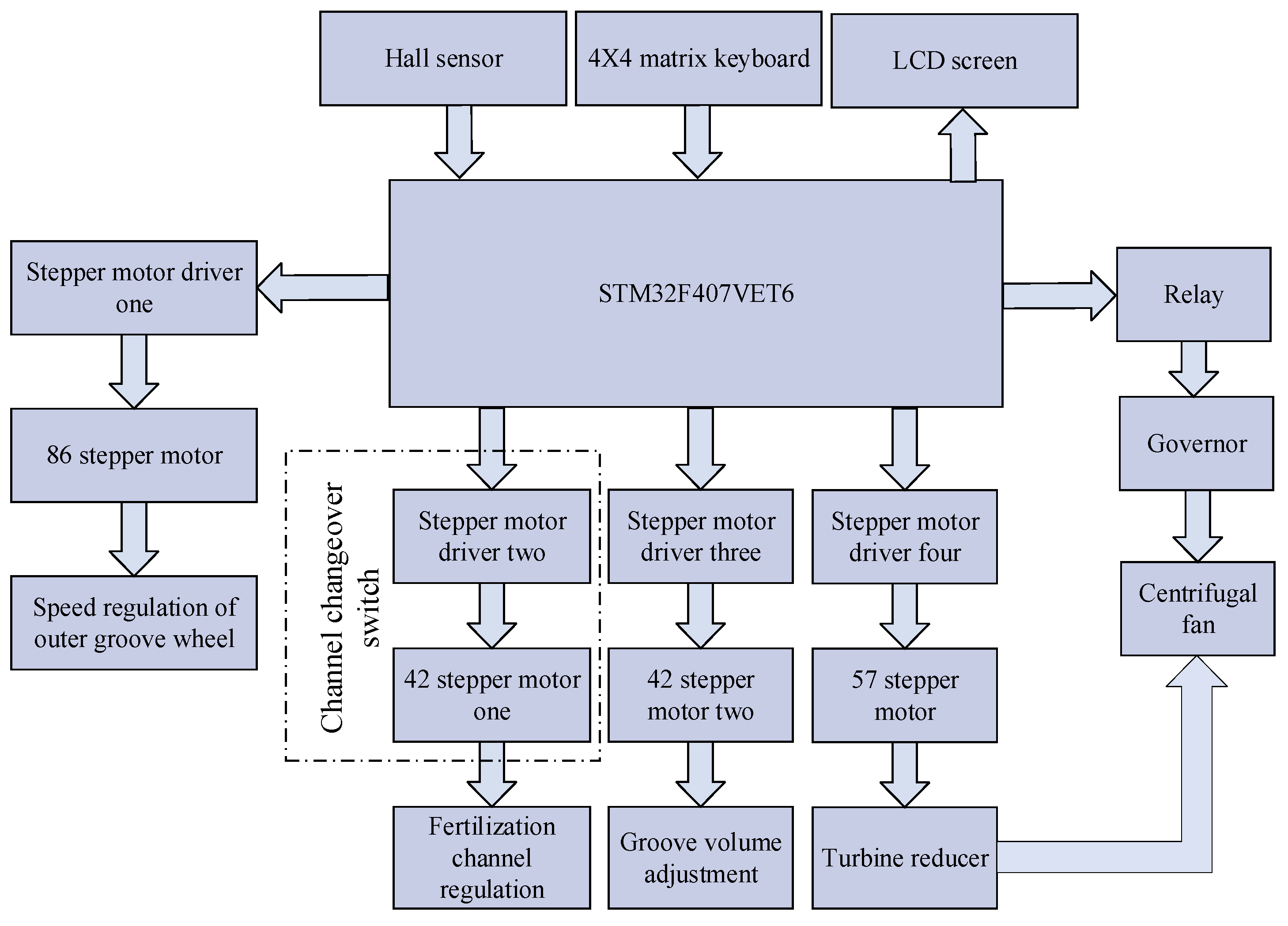
2.3. Control System Design

The hardware composition of the control system is shown in Figure 3. It comprises STM32F407VET6, Hall sensor, 4 × 4 matrix keyboard, LCD screen, relay, governor, 86-stepper motor, 57-stepper motor, 42-stepper motor, and stepper motor drivers.
The designed fertilization device allows for strip fertilization and spreading fertilization, while the automatic control flow is shown in Figure 4. During fertilization, the keyboard and the LCD screen allow human-computer interaction. The keyboard can implement the selection of the fertilizer types (NF, CF, OCF) and fertilization methods (strip fertilization and spreading fertilization). When strip fertilization is needed for crops with wide row spacing, the volume of the outer groove wheel can be adjusted automatically by the target fertilization amount and fertilization distance. Moreover, the volume of the outer groove wheel can also be adjusted automatically by using the keyboard to input the target fertilization amount and fertilization area when it is necessary to apply base fertilizer before crop planting or fertilize crops with high planting density. In addition, the fertilization mode, fertilizer type, fertilization length, fertilization area, fan swing speed, crawler car’s speed, and outer groove wheel’s speed are all displayed on the LCD in real-time.

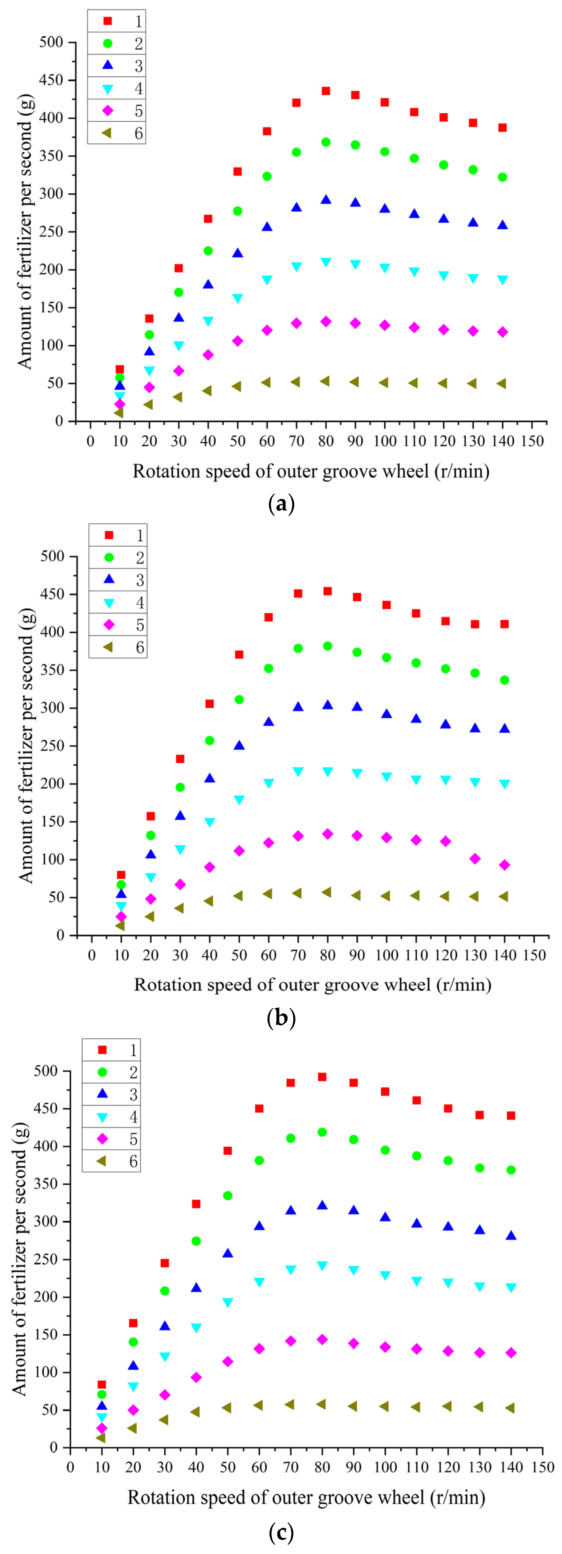
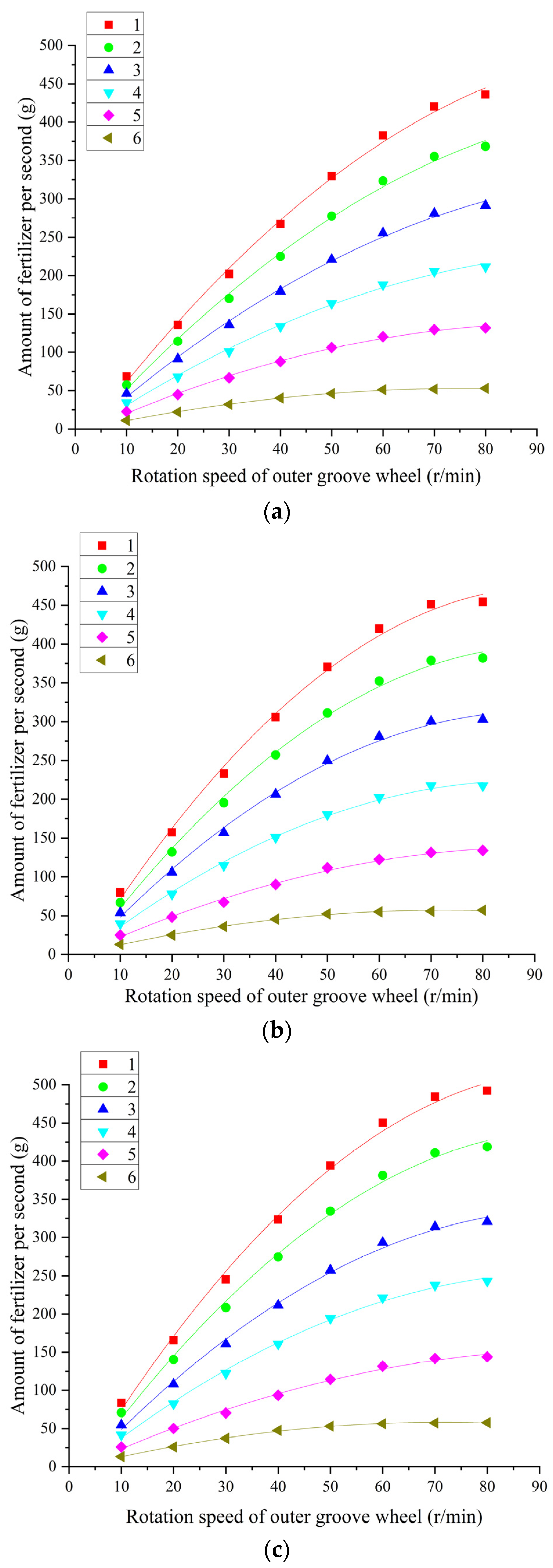
2.4. Determination of Fertilizer Discharge per Second at Different Speeds

Three granular fertilizers (NF, CF, OCF) are used in the experiments (Figure 5). The grain size, bulk density, and friction coefficient of the granular fertilizers are shown in Table 1. Firstly, those fertilizers are discharged for 30 s at speeds of 10, 20, 30, 40, 50, 60, 70, 80, 90, 100, 110, 120, 130, and 140 r/min of the outer groove wheel, respectively. Then the amount of fertilizer discharged is weighed by an electronic scale with an accuracy of 0.1 g. The amount of fertilizer is divided by 30 s to obtain the amount of fertilizer discharged per second. Finally, the test mentioned above is repeated three times at the same speed with the same fertilizer and takes the average value of the three tests as the amount of fertilizer discharged per second.
The results of fertilizer discharge per second at different speeds and groove volumes are shown in Figure 6. It can be seen from Figure 6 that under the same groove volume and speed, the higher the bulk density of granular fertilizer, the greater the fertilizer discharge per second of the outer groove wheel. The amount of fertilizer discharged from the three fertilizers per second begins to decrease when the rate of the outer groove wheel exceeds 80 r/min from groove volumes 1 to 5. Meanwhile, the amount of fertilizer discharged per second with groove volume 6 increases slightly, and the change is insignificant. Therefore, the fertilizer discharge amount is analyzed when the speed of the grooved wheel is between 10 r/min and 80 r/min. The least squares method is used to fit the amount of fertilizer discharged per second at different speeds, and linear and quadratic polynomial models are established. An F-test is carried out for these two models, the relevant parametric statistics of the linear model are shown in Table 2, and the parametric statistics of the quadratic polynomial models are shown in Table 3. The determination coefficient R2 of the linear model is between 0.849 and 0.975, the R2 of the quadratic polynomial models are all greater than 0.99, and the p-value of the F-test is less than 0.0001. The confidence level of the model is greater than 99.99%. Therefore, the quadratic polynomial model is better, and the fitting curves are shown in Figure 7, and the fitting curve is summarized as follows:
m s = B 1 n 2 + B 2 n + C
where m s is the amount of fertilizer discharged per second (g); n is the rotation speed of the outer groove wheel (r/min); C is a constant; B1 and B2 are coefficients. It can be observed from Table 3 that the constant and coefficients of the fitting relationship of different fertilizers under different grooved volumes are different. Specifically, the model determination coefficient R2 is greater than 0.99, which reveals that the model fitting degree is high.
It should be noted that the designed outer groove wheel has the same groove size and spacing. When the speed of the outer groove wheel is greater than 15 r/min, the fertilizer is discharged continuously. When the speed of the outer groove wheel is between 15 and 80 r/min, the amount of fertilizer discharged per second increases with the increase in speed. When the speed exceeds 80 r/min, the amount of fertilizer discharged per second decreases or changes little. Therefore, the ranges of fertilizer discharged per second can be calculated from the fitted quadratic polynomial relationship (Equation (1)) when the speed of the outer groove wheel is between 15 and 80 r/min. The corresponding calculated results are shown in Table 4.

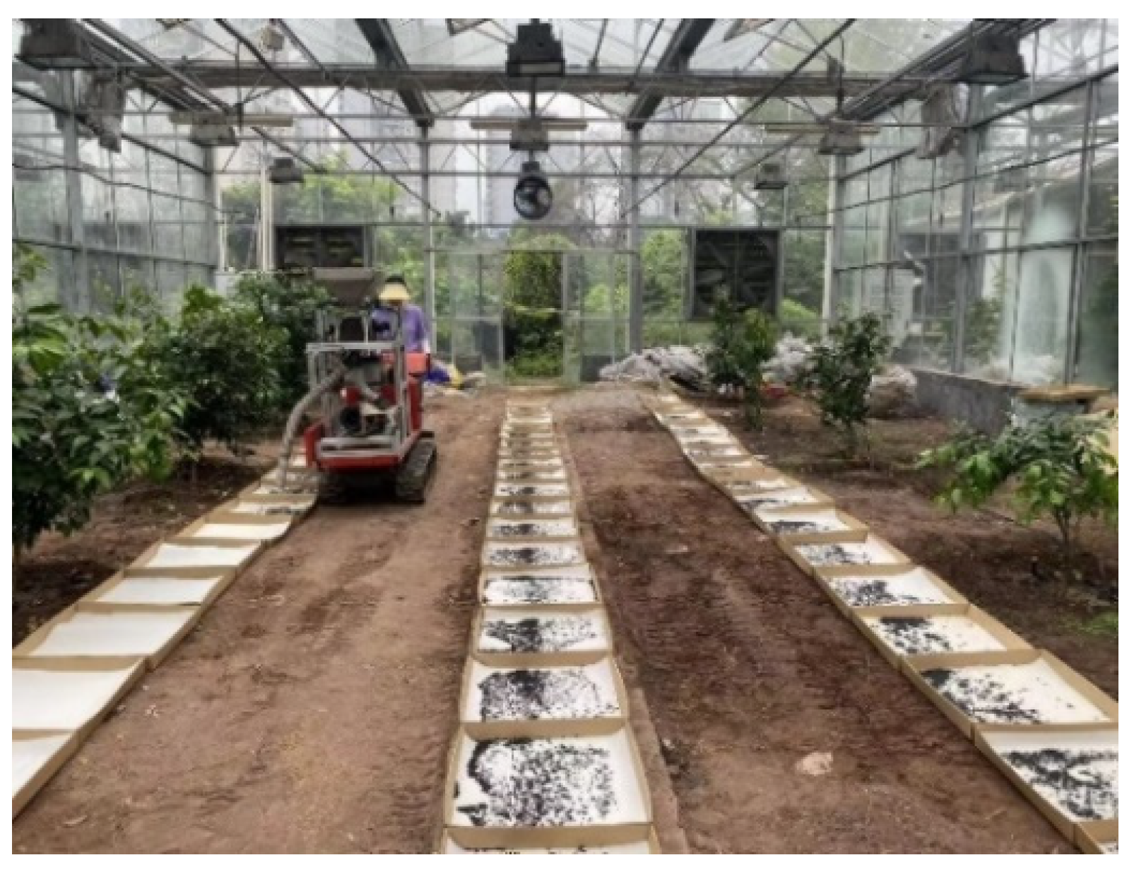
2.5. Strip Fertilization Test

In order to verify the accuracy and uniformity of strip fertilization by the designed device, an automatic variable-rate strip fertilization test between rows was conducted in a greenhouse, as shown in Figure 8.
According to the recommended application rate for crops [27], the target fertilizer rate per hectare is set as 200, 400, and 600 kg of NF, 800, 1000, 1200 kg of CF, 1400, 1600, and 1800 kg of OCF, respectively. Fertilization was conducted across three rows with a spacing of 1.2 m, and the effective fertilization distance of each row was 10 m [28]. Therefore, the corresponding fertilization amounts for this test distance are 720, 1440, and 2160 g of NF, 2880, 3600, and 4320 g of CF, and 5040, 5760, and 6480 g of OCF. During the fertilization process, 60 paper boxes with length × width × height of 500 mm × 500 mm × 100 mm are used to collect fertilizer. A sponge layer is placed in the box to prevent the fertilizer from popping out.
Firstly, the fertilizer type and fertilization mode are selected by the keyboard before fertilization. Then the required amount per second can be calculated automatically according to Equation (2) after inputting the target fertilization amount and distance. Moreover, the volume of the outer groove wheel is adjusted according to the range of fertilizer discharge in the different groove volumes shown in Table 4. During fertilization, the crawler car moves forward at 5 km/h. However, the speed of the crawler car always changes slightly due to the unevenness of the terrain. Therefore, a Hall sensor is applied to detect the crawler car’s speed in real-time and automatically adjust the speed of the outer groove wheel. Thus, the fertilizer discharge amount per second of the outer groove wheel is equal to the required amount in the actual fertilization process. Specifically, Equation (1) is equal to Equation (2), and it can be developed into Equation (3). The rotation speed of the outer groove wheel is converted, as the unknown variable in Equation (3), to calculate and obtain Equations (4) and (5).
m s = m t a r g e t × 1000 × 1.2 × l 10,000 × ( l / v )
B 1 n 2 + B 2 n + C = m t a r g e t × 1000 × 1.2 × l 10,000 × ( l / v )
n = B 2 B 2 2 4 × B 1 × ( C 3 × m t a r g e t × v 25 ) 2 B 1
n = B 2 + B 2 2 4 × B 1 × ( C 3 × m t a r g e t × v 25 ) 2 B 1
where n is the rotation speed of the outer groove wheel (r/min); m t a r g e t is the target fertilization amount per hectare (kg); m s is the fertilization amount per second (g); l is the fertilization distance (m); v is the crawler car’s speed (m/s); B 1 , B 2 , C are the parameters of the quadratic polynomial model in Table 3. It can be seen from Table 3 that the values of B 1 are all negative. In order to fertilize continuously, the rotation speed range of the outer groove wheel is 15~80 r/min. Therefore, Equation (5) is used as the automatic control model of strip fertilization. Based on the proposed automatic control model, the rotation speed of the outer groove wheel can be calculated automatically by a single-chip microcomputer. Then the PWM pulses are generated for automatic adjustment and ultimately completing the strip fertilization test.

2.6. Spreading Fertilization Test

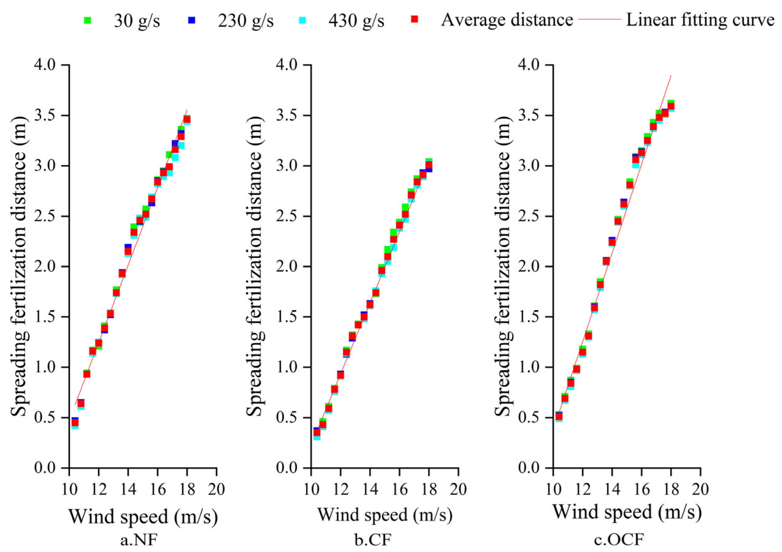
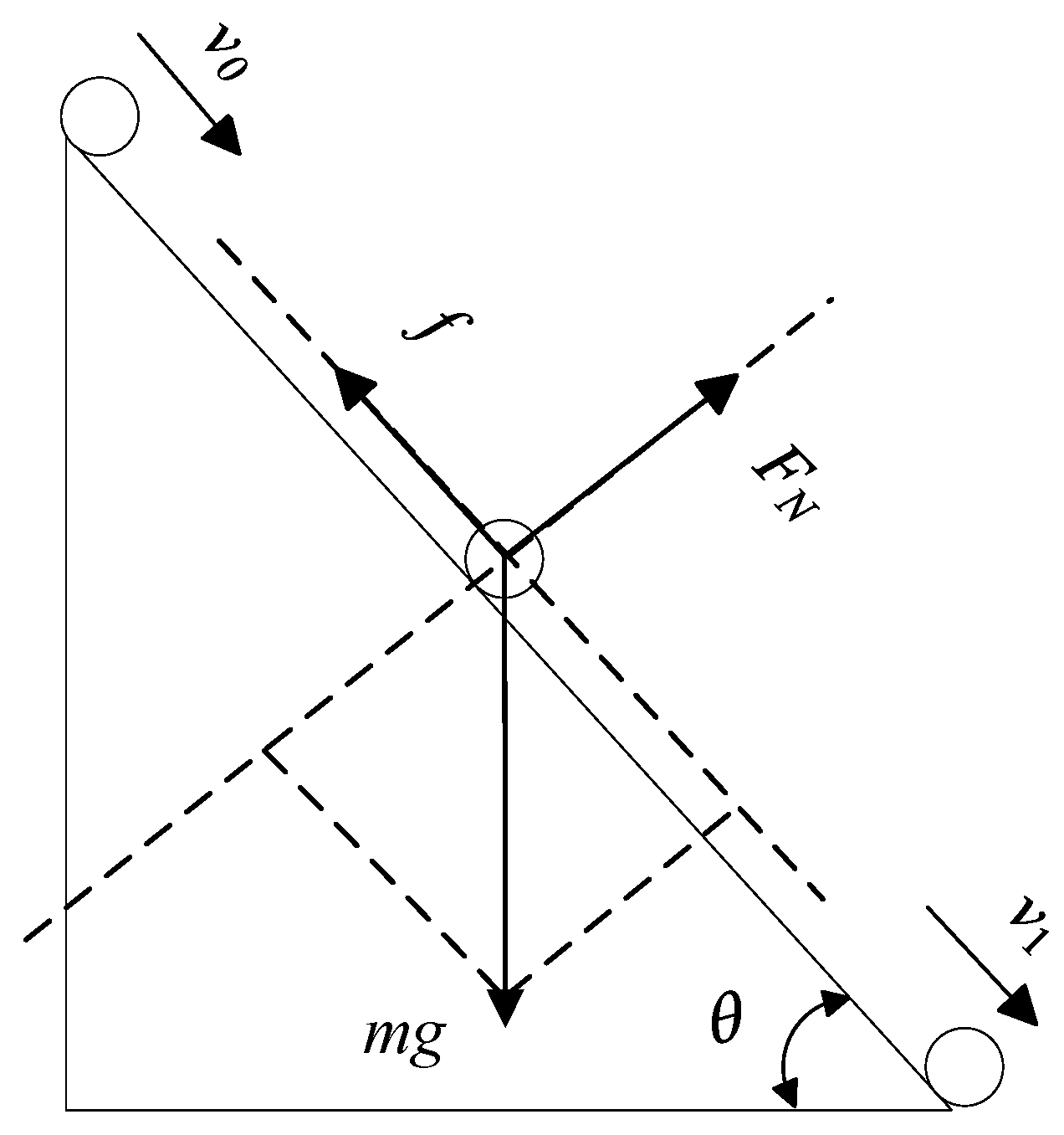
2.6.1. Calibration of the Static Spreading Fertilization Distance

Three granular fertilizers (NF, CF, OCF) were used to calibrate the spreading fertilization distance under different fan wind speeds. According to the range of fertilizer discharge speed under different groove volumes in Table 4, the fertilizer discharge speeds of the fertilizer discharge wheel were set to 30 g/s, 230 g/s, and 430 g/s, respectively. It is worth noting that the groove volume should be selected following the amount of fertilizer discharge. When multiple groove volumes satisfy the demands of the experiment, the smallest groove volume should be selected. According to Equation (1), the required speed of the outer groove wheel was calculated and adjusted. A fan governor was used to adjust the wind speed to 10.4, 10.8, 11.2, 11.6, 12, 12.4, 12.8, 13.2, 13.6, 14, 14.4, 14.8, 15.2, 15.6, 16, 16.4, 16.8, 17.2, 17.6, and 18 m/s, respectively. All fertilization tests were continuous for 30 s and repeated three times under each wind speed. Taking the far and near ends of the crawler car as the boundaries to form a clear boundary line, the spreading fertilization distance can be counted, and the fertilizing characteristics analyzed.
The results of the static spreading fertilization distance measurements are shown in Figure 9. Under the same wind speed condition, the spreading fertilization distance changes little when the fertilization discharge speed of the outer groove wheel is inconsistent. Therefore, the spreading fertilization distance is the average value under the three fertilizer discharge speeds. The univariate linear regression analysis is carried out on the spreading fertilization distance of the three fertilizers under different wind speeds. The regression model parameters are shown in Table 5. The model determination coefficient R2 is greater than 0.98, and the two are linearly related. The relationship is shown in the following equation:
W = a 1 v F + b 1
where W is the static spreading fertilization distance (m); v F is the wind speed of the fan (m/s); a 1 is the coefficient; b 1 is a constant.
The spreading distances of different granular fertilizers are different under the same fan wind speed and fertilizer discharge speed (Figure 9), mainly due to the fertilizers’ different friction factors and fertilizer quality. When the fertilizer moves in the fertilizer spreading channel, it is equivalent to performing a uniform acceleration motion on an inclined plane, as shown in Figure 10. Equation (7) can be obtained through force analysis, and the acceleration calculation is shown in Equation (8). The fertilizer velocity calculation at the outlet of the fertilizer channel is shown in Equation (9).
m × g × s i n θ u × m × g × c o s θ = m × a
a = g × ( s i n θ u × c o s θ )
v 1 = v 0 2 + 2 × a × s
where v 1 is the fertilizer velocity at the outlet of the spreading fertilization channel (m/s); v 0 is the fertilizer velocity at the entrance of the spreading fertilization channel (m/s); m is the quality of fertilizer (g); g is the acceleration of gravity (g/s2); θ is the angle between the spreading fertilization channel and the direction of the fan outlet (°); u is the friction coefficient (Table 1); s is the length of the spreading fertilization channel (m). Equation (8) and Equation (9) show that due to friction between the fertilizer and the discharge pipe and between fertilizers, the speed at which different granular fertilizers reach the fertilizer outlet is not equal. The larger the friction coefficient, the smaller the fertilizer speed at the fertilizer outlet, and the closer the fertilizer distance when the quality of the fertilizer is the same. In addition, the higher the quality of granular fertilizer (Table 1), the closer the distance of fertilization (Figure 9). When the friction coefficient is not significantly different, the distance of fertilization is mainly determined by the quality of granular fertilizer.

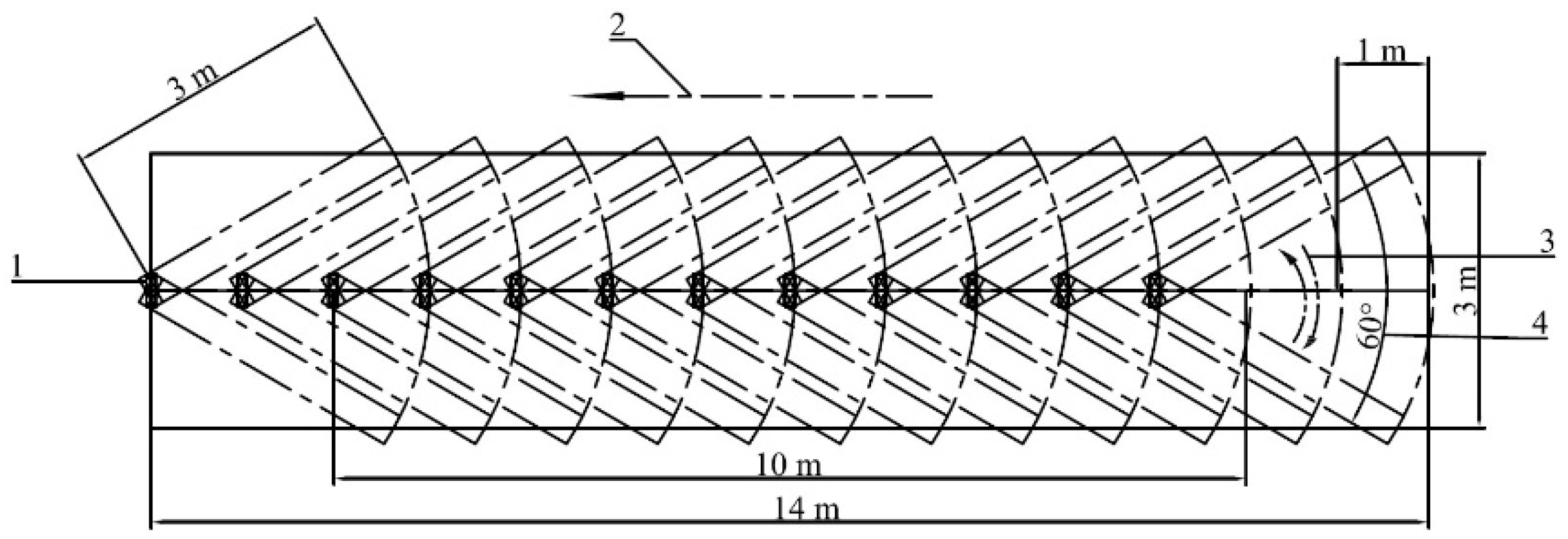
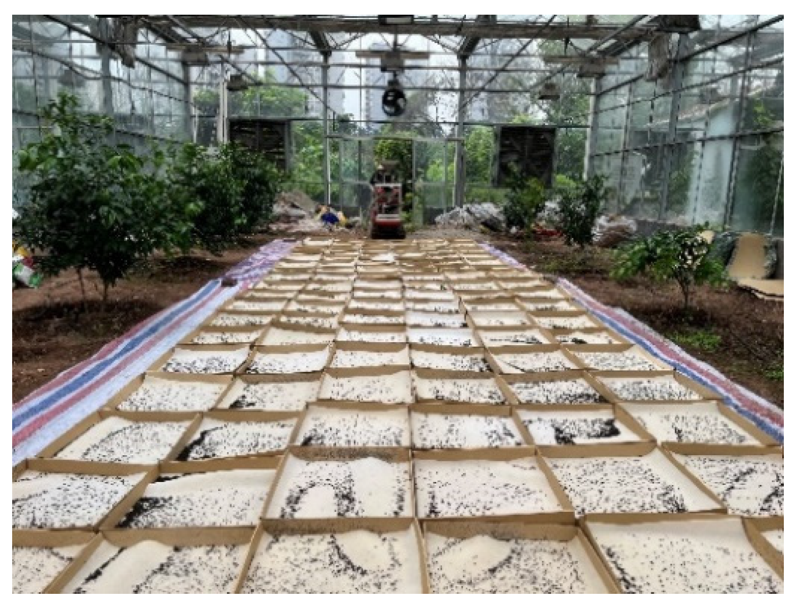
2.6.2. Superimposed Swing Spreading Fertilization Test

In order to verify the accuracy and uniformity of spreading fertilization by the designed device, an automatic variable-rate superimposed swing spreading fertilization test was conducted in a greenhouse. The effective fertilization distance was set to 10 m according to the “People’s Republic of China Fertilization Machinery Test Method [29].” Based on a linear model of spreading fertilization distance and wind speed, the static spreading fertilization width was set to 3 m. The superimposed swing spreading fertilization was carried out every 1 m, and the swing angle of the fan was 60°. The schematic diagram of fertilization is shown in Figure 11.
Firstly, the target fertilization amount per hectare was set as 200, 400, and 600 kg of NF, 800, 1000, and 1200 kg of CF, and 1400, 1600, and 1800 kg of OCF, respectively. Then, the corresponding amounts of fertilizer application in these test areas were 600, 1200, and 1800 g of NF, 2400, 3000, and 3600 g of CF, and 4200, 4800, and 5400 g of OCF. In order to facilitate statistical analyses of these test data, the crawler car adopted a reverse gear to move backward and carried out superimposed swing fertilization every 1 m. Furthermore, 120 paper boxes of 500 mm × 500 mm × 100 mm were used to collect the fertilizer, and a sponge layer was placed in every box to prevent the fertilizer from popping out. The fertilization test is shown in Figure 12.
The fertilizer type and fertilization mode are selected by the keyboard before fertilization. Moreover, the required fertilization amount per second can be calculated automatically according to Equation (10) by inputting the target fertilization amount and area. Then the volume of the outer groove wheel can be adjusted automatically according to the range of fertilizer discharge in the different groove volumes shown in Table 4. The fertilizer discharge amount per second of the fertilization device needs to equal the fertilizer discharge amount required in the actual fertilization to calculate the required fertilizer discharge wheel speed. That is, Equation (1) is equal to Equation (10), and then it can be developed into Equation (11). The speed of the outer groove wheel is converted as the unknown variable in Equation (11) to calculate and obtain Equation (12) and Equation (13).
m s = m t a r g e t × 1000 × 3 × 3 3 × 10,000 × ( 50 / n f )
B 1 n 2 + B 2 n + C = m t a r g e t × 1000 × 3 × 3 3 × 10,000 × ( 50 / n f )
n = B 2 B 2 2 4 × B 1 × ( C 3 × m t a r g e t × n f 500 ) 2 B 1
n = B 2 + B 2 2 4 × B 1 × ( C 3 × m t a r g e t × n f 500 ) 2 B 1
where n is the rotation speed of the outer groove wheel (r/min); m t a r g e t is the target fertilization amount per hectare (kg); m s is the fertilization amount per second (g); n f is the fan rotation speed (r/min); B 1 , B 2 and C are the parameters of the quadratic polynomial model in Table 3. It can be seen from Table 3 that the values of B 1 are all negative. In order to allow continuous fertilization, the rotation speed range of the outer groove wheel is 15~80 r/min. Therefore, Equation (13) is used as an automatic control model for spreading fertilization. According to the automatic control model, the rotation speed of the outer groove wheel can be calculated automatically using a single-chip microcomputer. Thus, the PWM pulses are generated for automatic adjustment and completion of the superimposed swing spreading fertilization test.

3. Results and Discussion

3.1. Strip Fertilization Test Results

After the strip fertilization test described in Section 2.5, an electronic scale is used to weigh the amount of fertilizer in each fertilizer collection box. The fertilizer collection box is recorded as N (1~60), and the corresponding fertilizer amount as m N (m1~m60). Furthermore, the total fertilizer amount is the sum of m1 to m60. The actual total fertilizer amount ( m a c t u a l ), the relative error ( R e ) of fertilizer amount and the coefficient of variation ( C v ) of uniformity are counted, as shown in Table 6. The R e and C v can be calculated by Equations (14) and (15).
R e = | m a c t u a l m t a r g e t × r s | m t a r g e t × r s × 100 %
C v = 1 N 1 ( m N m ) 2 m
where N is the number of fertilizer collection boxes; m N is the amount of fertilizer collected in each collection box; m is the absolute average amount of fertilizer in the 60 collection boxes; m a c t u a l is the actual total fertilizer amount; m t a r g e t is the target fertilization amount per hectare (kg); r s is the proportion of fertilization test area in a one hectare area.

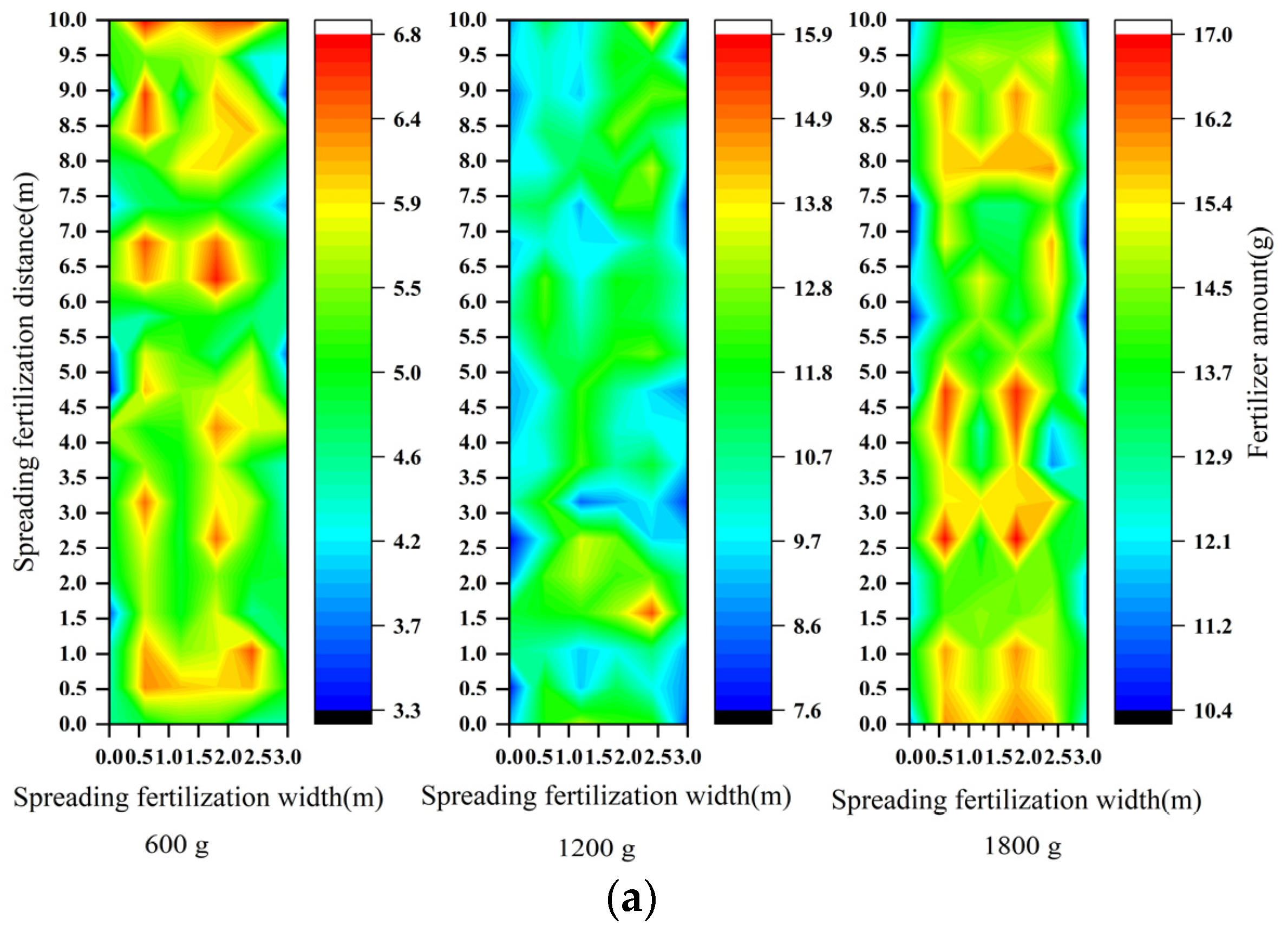
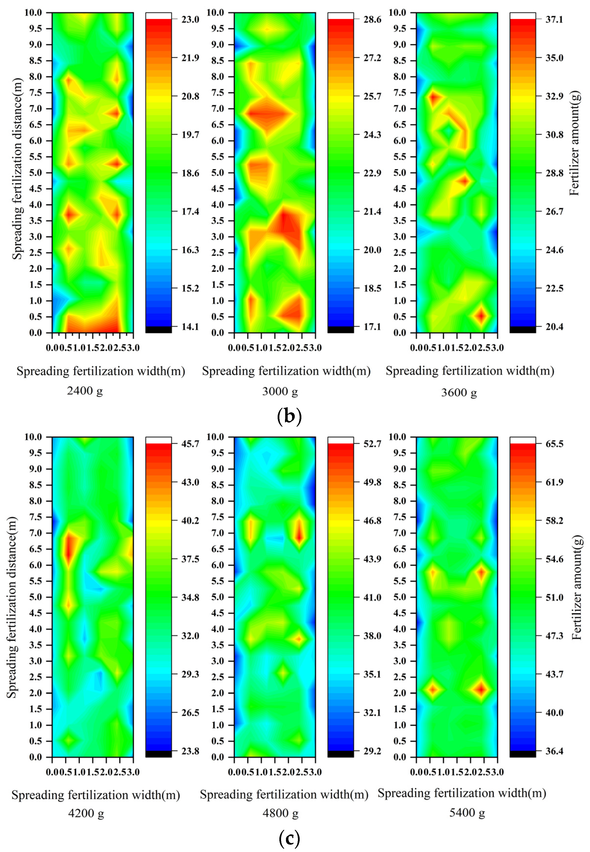
3.2. Superimposed Sowing Spreading Fertilization Test Results

The superimposed swing spreading fertilization test results in Section 2.6 were calculated, and an electronic scale was used to weigh the fertilizer amount in each fertilizer collection box. These test results are shown in Table 7, while the distribution of fertilizer using superimposed swing spreading fertilization is shown in Figure 13, respectively.
The calculation method of the relative error of the total fertilizer amount is consistent with Equation (14). It is the absolute value of the actual fertilizer amount minus the target fertilizer amount divided by the percentage of the target fertilizer amount. The coefficient of variation of uniformity is calculated by Equation (15). When calculating the coefficient of variation of lateral uniformity, N is the number of columns of the fertilizer collection box (1~6); m N is the total fertilizer amount in each column (m1~m6); m is the absolute average fertilizer amount of the six columns. When calculating the coefficient of variation of the total uniformity, N is the number of fertilizer collection boxes (1~120); m N is the fertilizer amount in each box (m1~m120); m is the absolute average number of fertilizer amounts in the 120 collection boxes.

3.3. Discussion

The strip fertilization test results showed that the maximum relative error of the nitrogen fertilizer amount was 6.81%. In addition, the maximum relative errors of compound and organic compound fertilizers were 6.2% and 6.83%, respectively. Moreover, the maximum coefficient of variation of uniformity of the three fertilizers was 8.91% (Table 6). Figure 13 shows that in the superimposed swing spreading fertilization test, the three granular fertilizers have more fertilizer in the middle and less fertilizer on either side. However, Table 7 shows that the maximum relative error of the fertilizer amount of granular nitrogen fertilizer was 7.31%. Meanwhile, it can also be known from Table 5 that the maximum relative error of compound fertilizer was 6.76%, and that of organic compound fertilizer was 7.43%. Moreover, the maximum coefficients of lateral and total uniformity variations were 9.88% and 14.17%, respectively. It can be confirmed that the designed device can meet the requirements that the uniformity of top dressing should be less than 40% and the uniformity of basal fertilizer should be less than 60% [30]. The fertilization device allows for automatic variable-rate strip fertilization and spreading fertilization of granular nitrogen fertilizer, compound fertilizer, and organic compound fertilizer at different fertilization rates.
The variable-rate fertilization structure of the designed fertilization device adopts an outer groove wheel fertilizer discharger. The outer groove wheel’s groove volume and rotation speed significantly impact fertilization amount, consistent with previous research studies [12,31]. When the rotation speed is below 80 r/min, the fertilizer discharge per second increases with the increase in rotation speed, consistent with previous studies [9,12]. However, when the rotation speed exceeds 80 r/min, the fertilizer discharge per second decreases or changes little. Linear and quadratic polynomial fitting was conducted on the amount of fertilizer discharged per second at different speeds, respectively. The linear fitting model had a coefficient of determination R2 between 0.849 and 0.975 (Table 2), consistent with the research results of [9,32]. However, the quadratic polynomial fitting effect is better than the linear fitting, and the model’s coefficient of determination is greater than 0.99 under different groove volumes, which can be used for further precise variable fertilization control. Compared with the fertilizer amount prediction model based on the radial basis function neural network built in [10], the quadratic polynomial regression model has a determination coefficient of 0.995~0.998 (Table 3), slightly lower than 0.99965 of the neural network prediction model. However, the quadratic polynomial model is simpler. The automatic variable-rate strip fertilization control model based on fertilization amount, fertilization speed, and fertilization distance is established using this model, which allows for automatic variable-rate strip fertilization that changes with the fertilization vehicle speed.
In addition, the control strategy of adjusting the groove volume first and then the rotation speed of the fertilizer discharge was adopted in this study, which effectively avoided the fertilizer blockage caused by adjusting the groove volume in the fertilization process. The fertilization device adopts the transmission mode of a synchronous belt and wheel to adjust the groove volume. It is verified by experiments that fertilizer can be discharged stably under different groove volumes and rotation speeds. Compared with other variable-rate fertilization devices [12,13], it has obtained a more extensive range of variable-rate fertilizer regulation, achieved variable-rate strip fertilization, and spread fertilization at the target rate of 200~1800 kg/ha. When spreading fertilization, the fertilization amount was controlled by adjusting the outer groove wheel fertilizer discharger, the centrifugal fan controlled the fertilization distance, and the superimposed swing spreading fertilization mode was used to improve the uniformity and accuracy of fertilization [21,25].
Therefore, the dual-mode automatic variable-rate fertilization device and control system is simple in operation, stable in fertilizer discharge, good in uniformity and accuracy in fertilization, and can be used for spreading a large amount of organic fertilizer and topdressing with a small amount of chemical fertilizer. It meets the needs of different fertilization amounts, types, and methods of China’s facility agriculture crop cultivation at different stages. This research can provide a theoretical basis and technical support for the research and application of multifunctional variable-rate fertilizer applicators.

4. Conclusions

(1)
In this study, a lightweight dual-mode automatic variable-rate fertilization device was designed, which meets the needs of applying a large amount of organic fertilizer as a base fertilizer and a small amount of chemical fertilizer as top-dressing. The volume adjustment of the fertilization device adopts the transmission mode of a synchronous belt and synchronous wheel, which is achieved by the stepping motor, resulting in improved accuracy and stability of variable-rate fertilization.
(2)
The automatic control model of variable-rate strip fertilization and spreading fertilization was established. According to the target fertilization amount, fertilization speed, fertilization distance, or fertilization area, the volume and rotation speed of the fertilization device can be automatically adjusted, while the precise variable-rate strip fertilization and spreading fertilization were achieved through dual variable adjustment. At the same time, the control strategy of adjusting the volume first and then the rotation speed can effectively solve the problem of blocking the fertilizer discharge device caused by adjusting the volume in the process of fertilization.
(3)
The maximum relative error of fertilization amount is 6.83%, and the maximum coefficient of variation of uniformity is 8.91% in strip fertilization experiments. In spreading fertilization experiments, the maximum relative error of fertilization amount is 7.43%, the maximum coefficient of variation of lateral uniformity is 8.91%, and the maximum coefficient of variation of total uniformity is 14.17%. This research study achieved precise variable-rate strip fertilization and spreading fertilization, which can meet the fertilization needs of different stages of facility agricultural crop cultivation in China for different fertilization amounts, types, and methods. The accurate application of fertilizers can effectively reduce fertilizer waste, improve fertilizer utilization efficiency, and promote sustainable development of agriculture.

Author Contributions

Conceptualization, Q.B.; methodology, H.L. and G.L.; software, Q.B. and H.L.; validation, H.L. and X.F.; formal analysis, X.F.; investigation, Q.B. and X.Z.; resources, G.L.; data curation, H.L. and X.Z.; writing—original draft preparation, Q.B.; writing—review and editing, G.L.; visualization, X.F.; supervision, G.L.; project administration, G.L.; funding acquisition, Q.B. and G.L. All authors have read and agreed to the published version of the manuscript.

Funding

This research was funded by the Key projects of the Chongqing Science and Technology Commission (cstc2019jscx-gksbX0001, cstc2018jszx-cyzdX0051) and the Fundamental Research Funds for the Central Universities (XDJK2020D017).

Institutional Review Board Statement

Not applicable.

Data Availability Statement

The data used to support the findings of this study are available from the corresponding author upon request.

Conflicts of Interest

The authors declare no conflict of interest.

References

  1. Loneragan, J.F. Plant nutrition in the 20th and perspectives for the 21st century. Plant Soil 1997, 196, 163–174. [Google Scholar] [CrossRef]
  2. Rahman, K.; Zhang, D. Effects of Fertilizer Broadcasting on the Excessive Use of Inorganic Fertilizers and Environmental Sustainability. Sustainability 2018, 10, 759. [Google Scholar] [CrossRef]
  3. Wu, H.; Ge, Y. Excessive application of fertilizer, agricultural non-point source pollution, and farmers’ policy choice. Sustainability 2019, 11, 1165. [Google Scholar] [CrossRef]
  4. Zhang, W. The integration of fertilizer soil pollution and agricultural industry economy based on Apriori algorithm. Arab. J. Geosci. 2021, 14, 1–11. [Google Scholar] [CrossRef]
  5. Lu, H.J.; Ye, Z.Q.; Zhang, X.L.; Lin, X.Y.; Ni, W.Z. Growth and yield responses of crops and macronutrient balance influenced by commercial organic manure used as a partial substitute for chemical fertilizers in an intensive vegetable cropping system. Phys. Chem. Earth. 2011, 36, 387–394. [Google Scholar] [CrossRef]
  6. Anonymous. Notice of the Ministry of agriculture and rural areas on printing and distributing the national development plan for Agricultural Mechanization in the 14th five years plan Nongji Fa [2021] No. 2. Gaz. Minist. Agric. Aff. People’s Repub. China 2022, 1, 48–60. [Google Scholar]
  7. Qian, L.; Lu, H.; Gao, Q.; Lu, H. Household-owned farm machinery vs. outsourced machinery services: The impact of agricultural mechanization on the land leasing behavior of relatively large-scale farmers in China. Land Use Pol. 2022, 115, 106008. [Google Scholar] [CrossRef]
  8. Sun, J.; Chen, H.; Duan, J.; Liu, Z.; Zhu, Q. Mechanical properties of the grooved-wheel drilling particles under multivariate interaction influenced based on 3D printing and EDEM simulation. Comput. Electron. Agric. 2020, 172, 105329. [Google Scholar] [CrossRef]
  9. Lv, H.; Yu, J.; Fu, H. Simulation of the operation of a fertilizer spreader based on an outer groove wheel using a discrete element method. Math. Comput. Model. 2013, 58, 842–851. [Google Scholar] [CrossRef]
  10. Bu, H.; Yu, S.; Dong, W.; Zhang, L.; Xia, Y. Analysis of the Effect of Bivariate Fertilizer Discharger Control Sequence on Fertilizer Discharge Performance. Agriculture 2022, 12, 1927. [Google Scholar] [CrossRef]
  11. Dang, Y.; Yang, G.; Wang, J.; Zhou, Z.; Xu, Z. A Decision-Making Capability Optimization Scheme of Control Combination and PID Controller Parameters for Bivariate Fertilizer Applicator Improved by Using EDEM. Agriculture 2022, 12, 2100. [Google Scholar] [CrossRef]
  12. Du, J.; Yang, Q.; Xia, J.; Li, G. Discrete Element Modeling and Verification of an Outer Groove Wheel Fertilizer Applicator with Helical Teeth. Trans. ASABE 2020, 63, 659–665. [Google Scholar] [CrossRef]
  13. Chen, C.; He, P.; Zhang, J.; Li, X.; Ren, Z.; Zhao, J.; Kang, J. A fixed-amount and variable-rate fertilizer applicator based on pulse width modulation. Comput. Electron. Agric. 2018, 148, 330–336. [Google Scholar] [CrossRef]
  14. Dun, G.; Gao, Z.; Liu, Y.; Ji, W.; Mao, N.; Wu, X.; Liu, W. Optimization design of fertilizer apparatus owned arc gears based on discrete element method. Int. J. Agric. Biol. Eng. 2021, 14, 97–105. [Google Scholar] [CrossRef]
  15. Sugirbay, A.M.; Zhao, J.; Nukeshev, S.O.; Chen, J. Determination of pin-roller parameters and evaluation of the uniformity of granular fertilizer application metering devices in precision farming. Comput. Electron. Agric. 2020, 179, 105835. [Google Scholar] [CrossRef]
  16. Zhang, X.; Pei, Y.; Chen, Y.; Song, Q.; Zhou, P.; Xia, Y.; Liu, X. The Design and Experiment of Vertical Variable Cavity Base Fertilizer Fertilizing Apparatus. Agriculture 2022, 12, 1793. [Google Scholar] [CrossRef]
  17. Chang, Y.K.; Zaman, Q.U.; Farooque, A.; Chattha, H.; Read, S.; Schumann, A. Sensing and control system for spot application of granular fertilizer in wild blueberry field. Precis. Agric. 2017, 18, 210–223. [Google Scholar] [CrossRef]
  18. Chen, H.; Zheng, J.; Lu, S.; Zeng, S.; Wei, S. Design and experiment of vertical pneumatic fertilization system with spiral Geneva mechanism. Int. J. Agric. Biol. Eng. 2021, 14, 135–144. [Google Scholar] [CrossRef]
  19. Ishola, T.A.; Yahya, A.; Shariff, A.R.M.; Aziz, S.A. A novel variable rate pneumatic fertilizer applicator. Instrum. Sci. Technol. 2014, 42, 369–384. [Google Scholar] [CrossRef]
  20. Qi, X.; Zhou, Z.; Lin, S. Design of fertilizer spraying device of pneumatic variable-rate fertilizer applicator for rice production J/OL. Trans. Chin. Agric. Mach. 2018, 49, 164–170. [Google Scholar]
  21. Zha, X.; Zhang, G.; Zhang, S.; Hou, Q.; Wang, Y.; Zhou, Y. Design and experiment of centralized pneumatic deep precision fertilization device for rice transplanter. Int. J. Agric. Biol. Eng. 2020, 13, 109–117. [Google Scholar] [CrossRef]
  22. Cool, S.R.; Pieters, J.G.; Seatovic, D.; Mertens, K.C.; Nuyttens, D.; Van De Gucht, T.C.; Vangeyte, J. Development of a stereovision-based technique to measure the spread patterns of granular fertilizer spreaders. Sensors 2017, 17, 1396. [Google Scholar] [CrossRef] [PubMed]
  23. Shi, Y.Y.; Chen, M.; Wang, X.C.; Odhiambo, M.O.; Ding, W.M. Numerical simulation of spreading performance and distribution pattern of centrifugal variable-rate fertilizer applicator based on DEM software. Comput. Electron. Agric. 2018, 144, 249–259. [Google Scholar]
  24. Shi, Y.; Hu, Z.; Wang, X.; Odhiambo, M.O.; Ding, W. Motion analysis and system response of fertilizer feed apparatus for paddy variable-rate fertilizer spreader. Comput. Electron. Agric. 2018, 153, 239–247. [Google Scholar]
  25. Guan, Z.; Mu, S.; Jiang, T.; Li, H.; Zhang, M.; Wu, C.; Jin, M. Development of Centrifugal Disc Spreader on Tracked Combine Harvester for Rape Undersowing Rice Based on DEM. Agriculture 2022, 12, 562. [Google Scholar] [CrossRef]
  26. Yang, X.F. Technical Manual for Fertilization of Melon and Vegetable; China Agriculture Press: Beijing, China, 2001; pp. 93–97. [Google Scholar]
  27. Nations, F. Fertilizers and Their Use: A Pocket Guide for Extension Officers; Food & Agriculture Org: Rome, Italy, 2000; pp. 1–78. [Google Scholar]
  28. Yang, Z.W.; Ma, H.L.; Zhang, X.S.; Ma, X. GB/T 20346.1-2006; Equipment for Distributing Fertilizers—Test Methods—Part 2: Fertilizer Distributor in Lines. Standards Press of China: Beijing, China, 2006; pp. 1–17.
  29. Yang, Z.W. GB/T 20346.2-2006; Equipment for Distributing Fertilizers—Test Methods—Part 1: Full Width Fertilizer Distributors. Standards Press of China: Beijing, China, 2006; pp. 1–18.
  30. Ministry of Agriculture of the PRC. Technical Specifications of Quality Evaluation for Fertilizing Machinery; China Agriculture Press: Beijing, China, 2006; pp. 1–10. [Google Scholar]
  31. Zhu, Q.; Wu, G.; Chen, L.; Zhao, C.; Meng, Z. Influences of structure parameters of straight flute wheel on fertilizing performance of fertilizer apparatus. Trans. CSAE 2018, 34, 12–20. [Google Scholar]
  32. Zhang, J.; Liu, G.; Luo, C.; Hu, H.; Huang, J. MOEA/D-DE based bivariate control sequence optimization of a variable-rate fertilizer applicator. Comput. Electron. Agric. 2019, 167, 105063. [Google Scholar] [CrossRef]
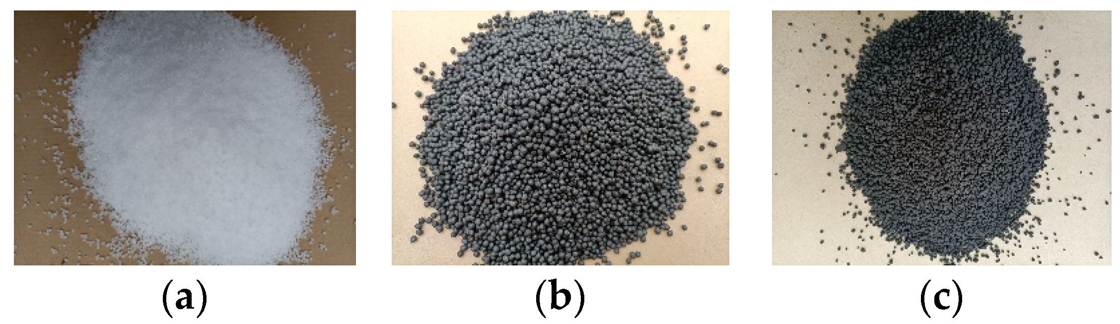
Figure 1. Overall structure of the fertilization device: 1. Material box; 2. 42-stepper motor; 3. Outer groove wheel; 4. Channel changeover switch; 5. Spreading fertilization channel; 6. Strip fertilization channel; 7. Centrifugal fan; 8. Spreading fertilizer export; 9. Crawler car; 10. Hall sensor; 11. Battery; 12. 86-stepper motor; 13. Control box; 14. LCD screen; 15. 4 × 4 matrix keyboard.
Agriculture 13 01138 g001
Figure 2. Main working structure of the fertilization device. (a) Double variable-rate outer groove wheel structure; (b) Double channel structure.
Agriculture 13 01138 g002
Figure 3. Hardware composition of the control system.
Agriculture 13 01138 g003
Figure 4. Automatic control flow chart of variable-rate fertilization.
Agriculture 13 01138 g004
Figure 5. Three kinds of granular fertilizer. (a) NF; (b) CF; (c)OCF.
Agriculture 13 01138 g005
Figure 6. Fertilizer discharged per second at different speeds and groove volumes. (a) NF; (b) CF; (c) OCF.
Agriculture 13 01138 g006
Figure 7. The relationship between the amount of fertilizer per second and the rotation speed. (a) Polynomial fitting of NF; (b) Polynomial fitting of CF; (c) Polynomial fitting of OCF.
Agriculture 13 01138 g007
Figure 8. Strip fertilization test.
Agriculture 13 01138 g008
Figure 9. Static spreading fertilization distance at different wind speeds.
Agriculture 13 01138 g009
Figure 10. Stress analysis diagram of granular fertilizer in the fertilizer distribution channel.
Agriculture 13 01138 g010
Figure 11. Schematic diagram of superimposed swing spreading fertilization: 1. The position of the fertilizing fan; 2. The moving direction of the crawler car; 3. The swing direction of the fan; 4. The swing angle of the fan.
Agriculture 13 01138 g011
Figure 12. Superimposed swing spreading fertilization test.
Agriculture 13 01138 g012
Figure 13. Distribution diagram of test results of superimposed swing spreading fertilization: (a) NF; (b) CF; (c) OCF.
Agriculture 13 01138 g013aAgriculture 13 01138 g013b
Table 1. Parameters of granular fertilizers (NF, CF, OCF).
Fertilizer
Type
Grain Size
(mm)
Bulk Density
(g/cm3)
Dynamic Friction
Coefficient
(Fertilizer–PVC Pipe)
Dynamic Friction
Coefficient
(Fertilizer–Fertilizer)
NF2.0~3.580.750.060.16
CF3.35~5.60.840.140.23
OCF1.0~4.750.890.090.18
Table 2. Linear regression model parameters.
Fertilizer
Type
Groove Volume CoefficientConstantR2p-Value
NF15.47733.7400.9743.535 × 10−6
24.63527.8680.9753.278 × 10−6
33.65123.4120.9733.736 × 10−6
42.64119.3040.9677.109 × 10−6
51.62615.5460.9522.264 × 10−5
60.60011.4630.8922.574 × 10−4
CF15.61556.2630.9473.008 × 10−5
24.71947.1590.9472.962 × 10−5
33.72939.3000.9433.762 × 10−5
42.66130.3040.9394.591 × 10−5
51.62518.1340.9463.211 × 10−5
60.62714.1670.8625.412 × 10−4
OCF16.11854.5850.9541.907 × 10−5
25.19746.0710.9551.769 × 10−5
33.97036.2860.9532.043 × 10−5
43.00027.9780.9541.896 × 10−5
51.77416.6500.9591.391 × 10−5
60.63415.0010.8497.111 × 10−4
Table 3. Quadratic polynomial model parameters.
Fertilizer
Type
Groove Volume B1B2CR2p-Value
NF1−0.0398.966−24.4170.9964.102 × 10−7
2−0.0327.536−20.4950.9964.502 × 10−7
3−0.0266.017−16.0180.9963.246 × 10−7
4−0.0214.564−12.7480.9964.095 × 10−7
5−0.0163.100−9.0200.9963.414 × 10−7
6−0.0101.460−2.8600.9992.594 × 10−8
CF1−0.05910.928−32.2840.9956.571 × 10−7
2−0.0509.176−27.1260.9956.107 × 10−7
3−0.0417.417−22.1630.9965.561 × 10−7
4−0.0305.395−15.2690.9964.876 × 10−7
5−0.0173.160−7.4480.9951.393 × 10−6
6−0.0111.650−2.8910.9972.125 × 10−7
OCF1−0.05911.429−33.9320.9956.796 × 10−7
2−0.0499.670−28.4750.9965.055 × 10−7
3−0.0397.481−22.2270.9964.968 × 10−7
4−0.0295.632−15.9110.9973.126 × 10−7
5−0.0163.196−7.0510.9951.490 × 10−6
6−0.0121.726−3.2010.9988.829 × 10−8
Table 4. The range of fertilizer discharged per second at speeds of 15~80 r/min.
Fertilizer TypeGroove VolumeFertilizer Discharged per Second (g)
15 r/min80 r/min
NF1101.37445.20
285.30376.33
368.31297.00
450.92216.05
533.79134.04
616.8852.52
CF1118.36464.32
299.37390.13
379.89309.43
458.84222.41
536.12136.53
619.3056.17
OCF1124.22502.76
2105.39427.04
381.21326.62
462.00247.77
537.34147.52
619.9657.42
Table 5. Linear model parameters of spreading fertilization distance and wind speed.
Fertilizer Typea1b1R2
NF0.385−3.3740.988
CF0.361−3.4010.996
OCF0.440−4.0270.984
Table 6. Strip fertilization test results.
Fertilizer TypeTheoretical Fertilizer Amount (g)Actual Fertilizer Amount (g)Relative ErrorCoefficient of Variation of Uniformity
NF720764.46.17%8.59%
14401341.96.81%7.88%
21602078.43.78%8.76%
CF28803017.34.77%8.73%
36003823.26.20%8.81%
43204456.93.17%5.90%
OCF50404695.86.83%7.94%
57605529.64.00%8.87%
64806230.53.85%8.91%
Note: Theoretical fertilizer amount is the value of ( m t a r g e t × r s ) .
Table 7. Superimposed sowing spreading fertilization test results.
Fertilizer TypeTheoretical Fertilizer Amount (g)Actual Fertilizer Amount (g)Relative ErrorCoefficient of Variation of Lateral UniformityCoefficient of Variation of Total Uniformity
NF600640.36.72%9.56%13.97%
12001277.96.49%8.71%14.17%
18001668.47.31%9.70%11.61%
CF24002259.95.84%8.70%10.97%
300027986.73%9.58%12.22%
36003356.66.76%9.88%13.09%
OCF42003905.97.00%8.79%12.86%
48004535.75.51%8.86%12.33%
54005801.17.43%9.48%11.07%
Note: Theoretical fertilizer amount is the value of ( m t a r g e t × r s ) .
Disclaimer/Publisher’s Note: The statements, opinions and data contained in all publications are solely those of the individual author(s) and contributor(s) and not of MDPI and/or the editor(s). MDPI and/or the editor(s) disclaim responsibility for any injury to people or property resulting from any ideas, methods, instructions or products referred to in the content.

