
Analysis and Design of Confined Masonry Structures: Review and Future Research Directions


Abstract
:1. Introduction
2. Research Significance
3. Performance
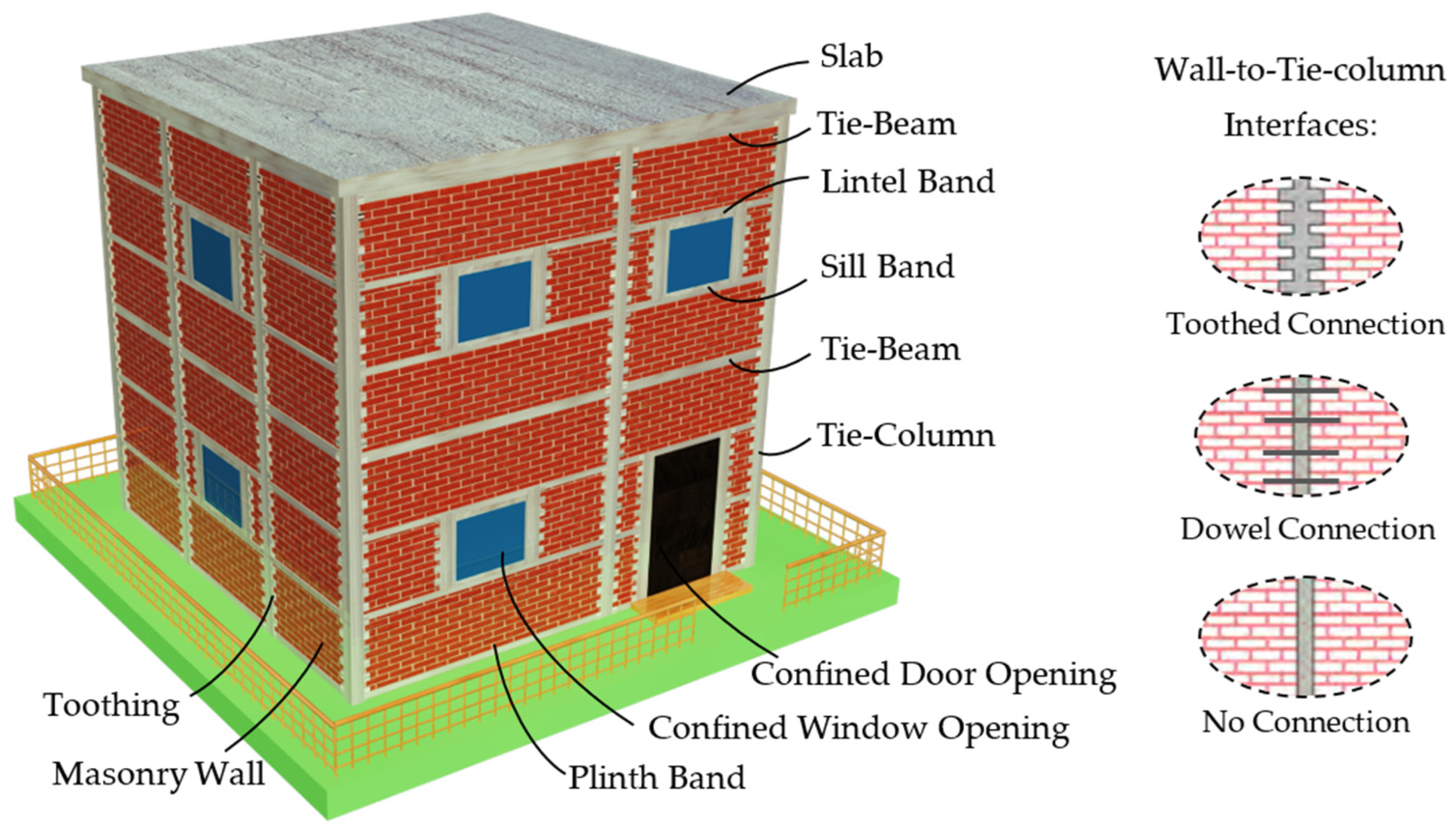
3.1. General Performance
3.2. Experimental Performance
3.2.1. Influence of Some Important Parameters on Behavior of CM Walls
- (i)
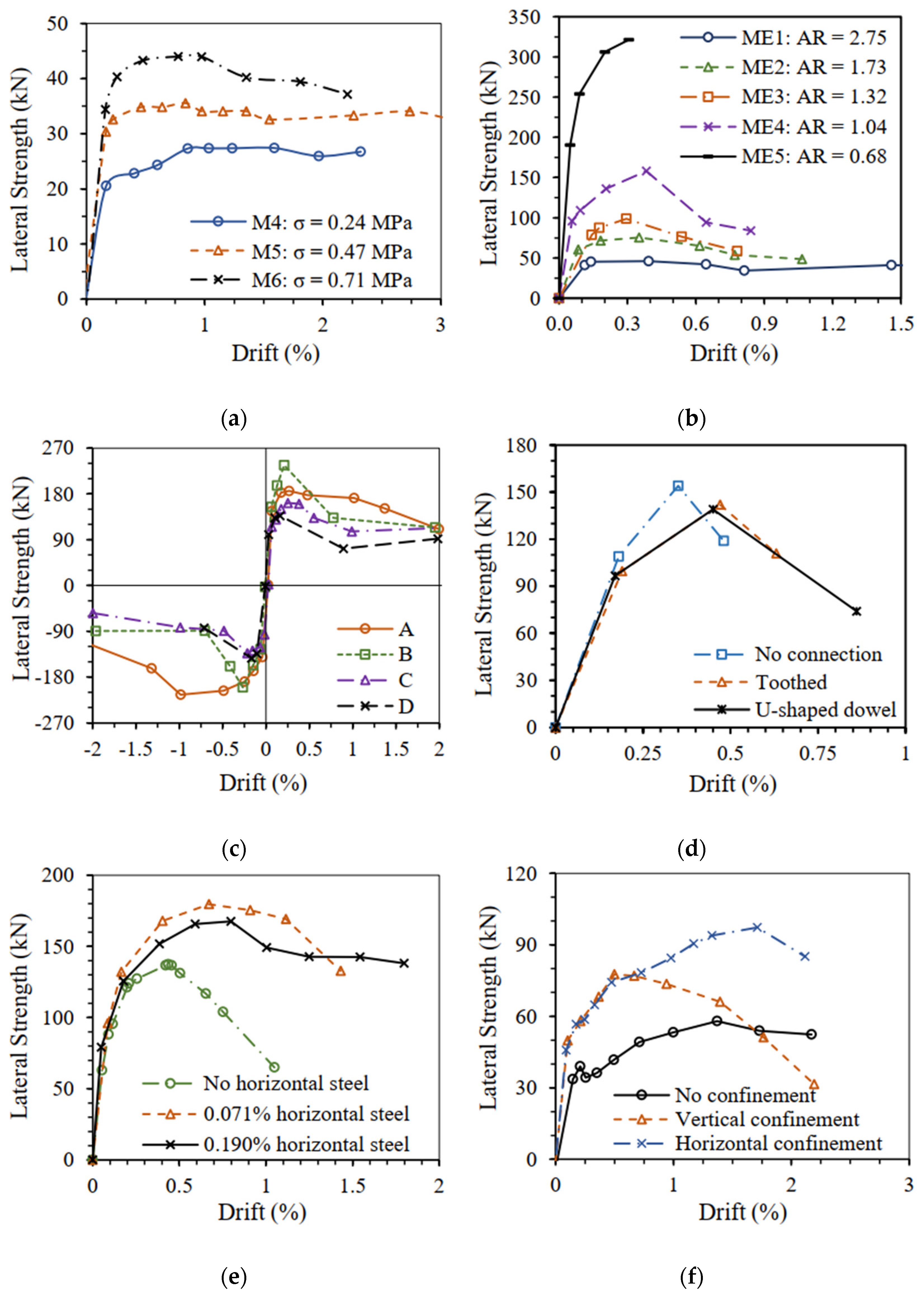
- Type of masonry
- (ii)
- Overburden load
- (iii)
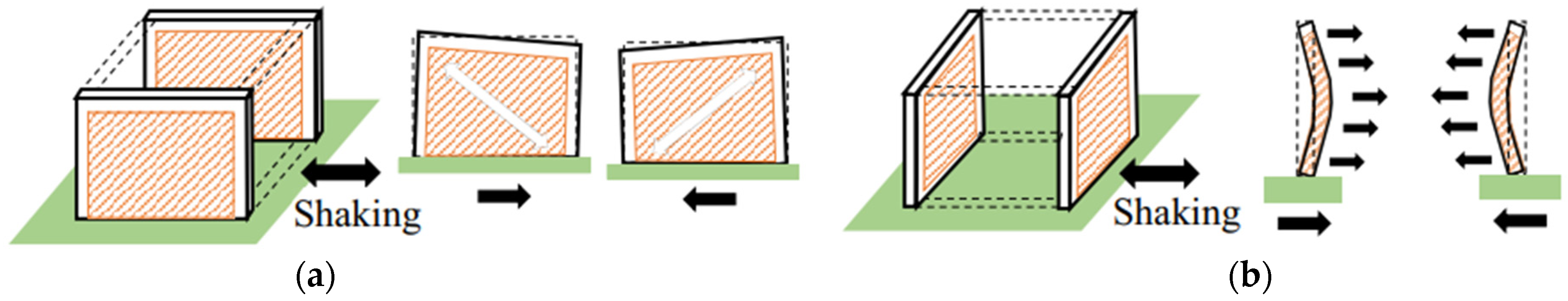
- Aspect ratio
- (iv)
- Number of tie-columns and their spacing
- (v)
- Tie-column reinforcement
- (vi)
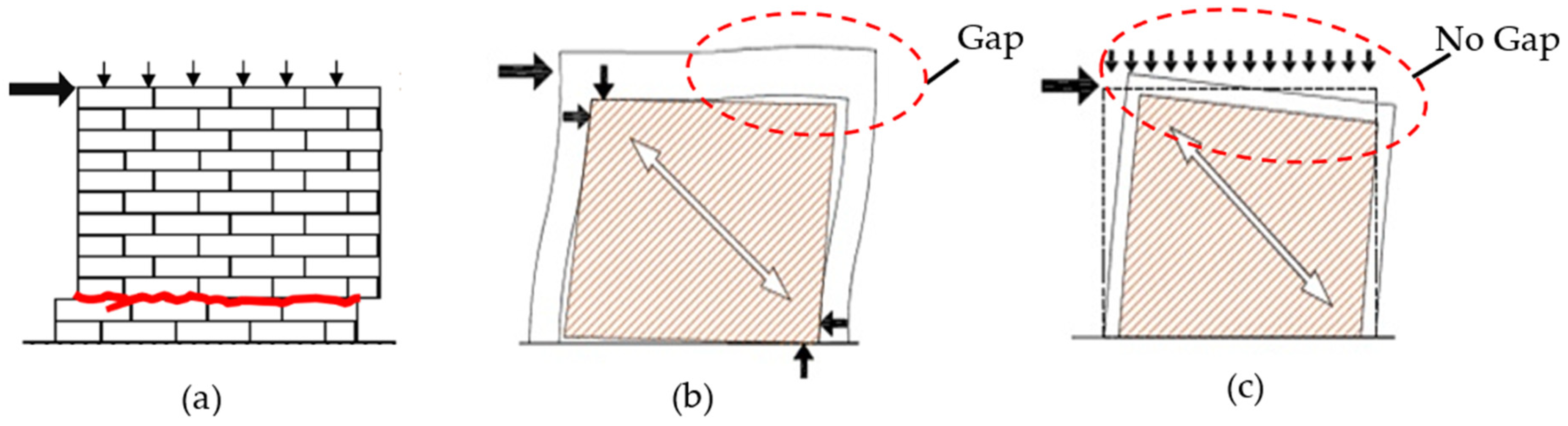
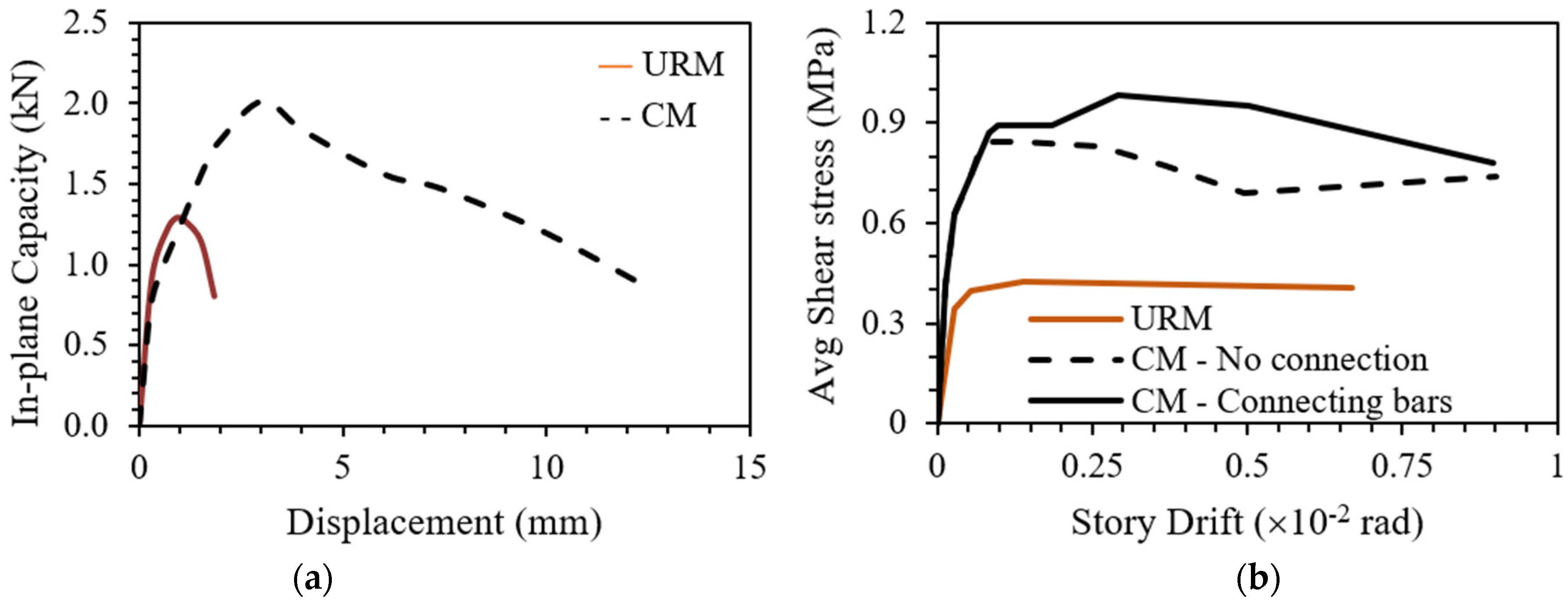
- Connection between wall and tie-column
- (vii)
- Reinforcement in wall
- (viii)
- Opening confinement
- (ix)
- Number of stories
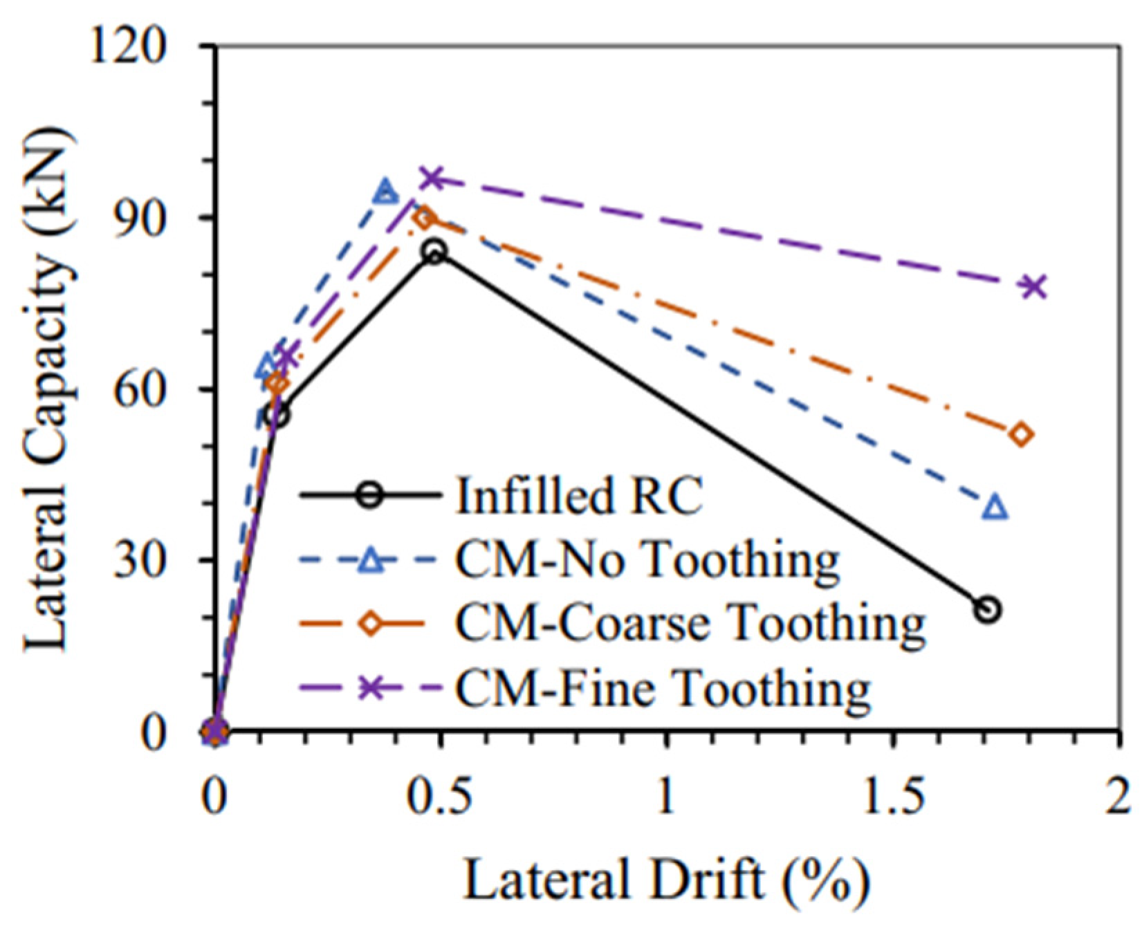
3.2.2. Comparison of CM with Other Similar Building Typologies
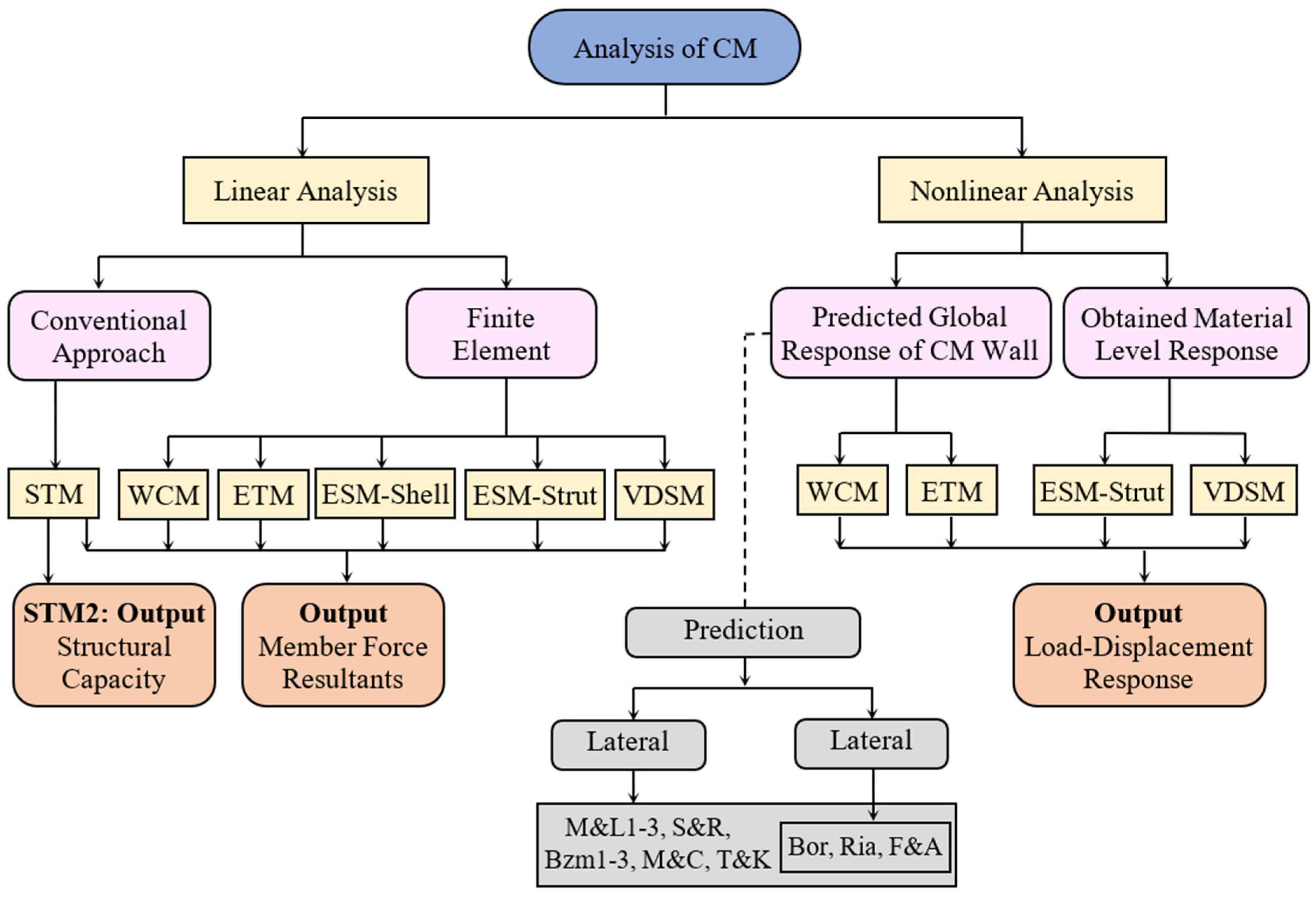
4. Analysis Methods
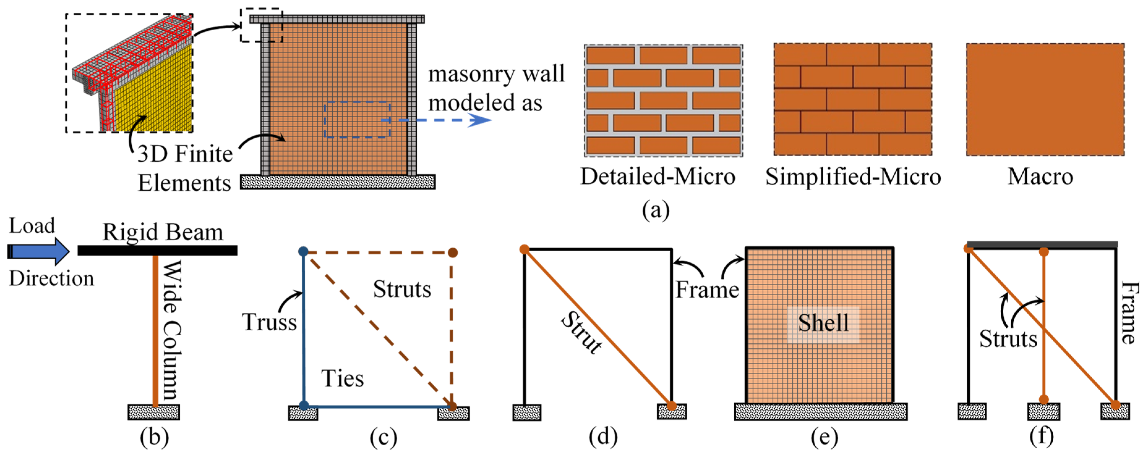
4.1. Finite Element Method (FEM)
4.2. Wide Column Method (WCM)
4.3. Strut-and-Tie Method (STM)
4.4. Equivalent Truss Method
4.5. Equivalent Strut Method or Equivalent Shell Method (ESM)
4.6. Vertical-Diagonal Strut Method (VDSM)
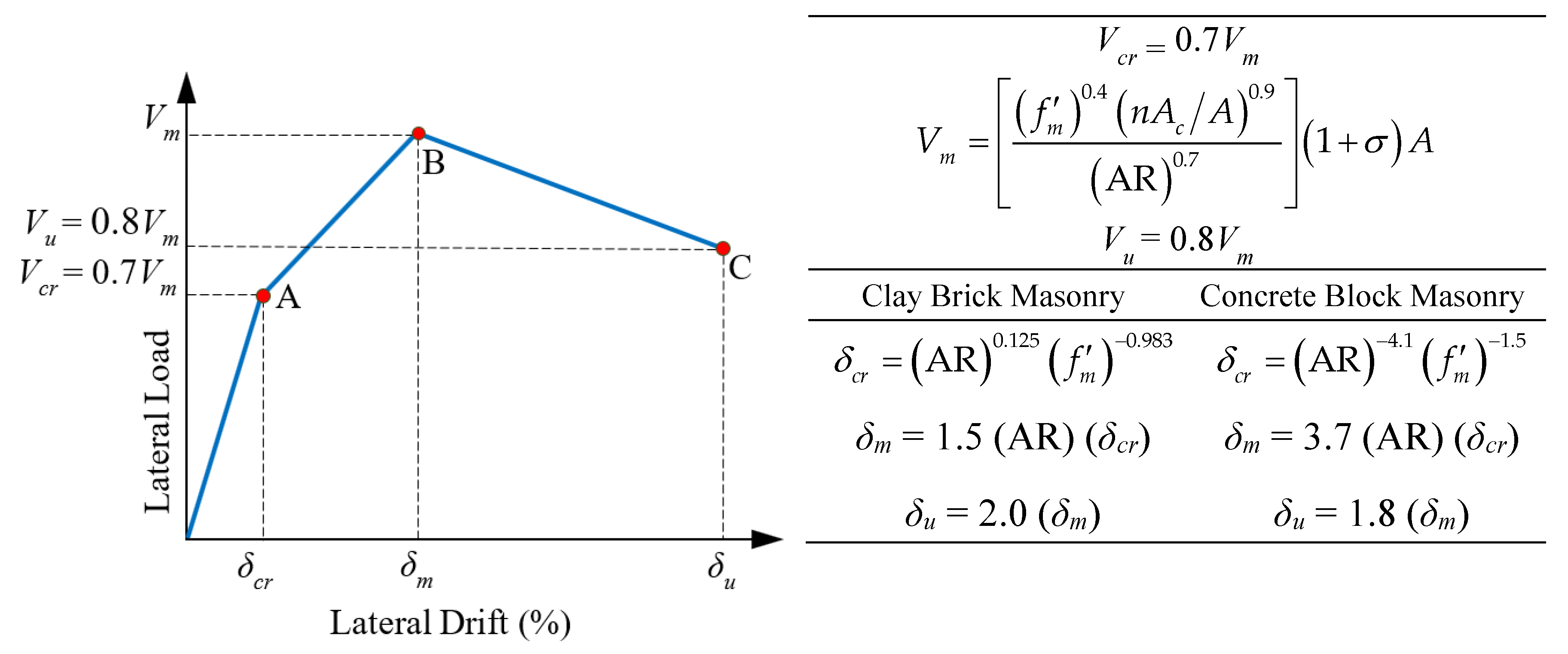
4.7. Using Backbone Curves
5. Design Methodologies
5.1. Basic Design
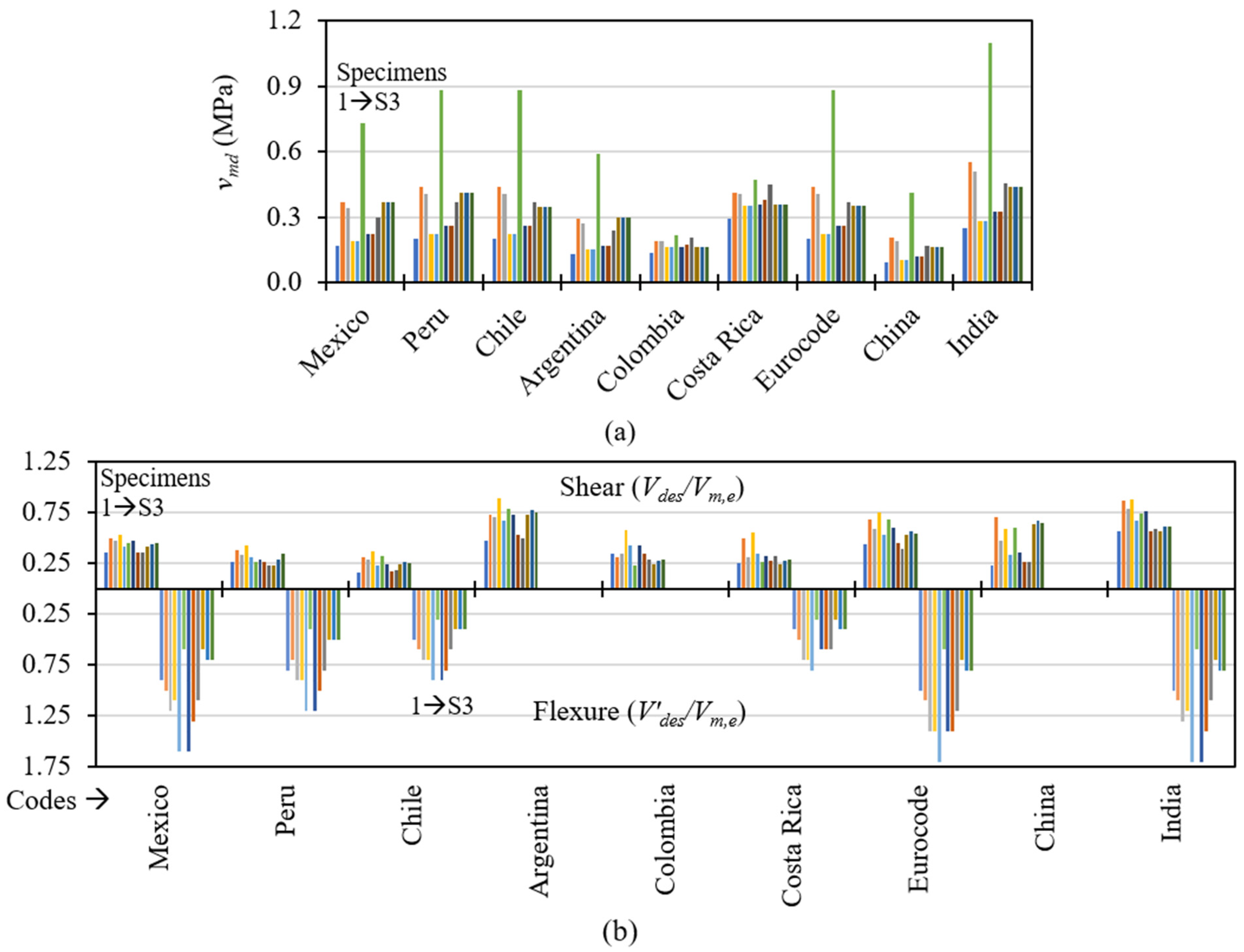
5.2. Estimation of Design Forces for CM Wall
5.3. Design Force Distribution in Different CM Elements
6. Research Challenges and Future Directions
- Aspect ratio has a significant influence on the behavior of CM walls. The available experimental studies are limited and do not provide a sufficient understanding of the influence of AR on CM behavior, especially considering the significant variations in material and construction methodologies throughout the world. Further research is needed to develop a comprehensive understanding of the influence of AR on the behavior of CM structures. Limited studies have been carried out on slender CM walls; therefore, additional studies are required to be carried out for walls with ARs greater than one.
- The current modeling and simulation techniques available for analyzing CM buildings have limited applications. A suitable interaction model is needed to simulate the interface between wall panel and confining elements. A comprehensive numerical model that can accurately simulate the response of CM walls to both gravity and lateral loads is yet to be fully developed. The development of modeling and simulation techniques is specifically required for multi-storey CM buildings and CM walls with openings.
- The literature reveals significant variations in the size and detailing of tie-elements used in CM constructions. Additional studies are needed to evaluate the behavior of tie-columns, particularly in terms of reinforcement yielding and damage patterns with variations in different parameters such as relative strength and stiffness of wall and confining elements and aspect ratio. It is important to evaluate the limiting size and detailing of tie-columns such that the system does not behave like an RC frame building.
- The current literature does not provide a clear discussion of the distribution of design lateral forces to masonry walls and tie-columns. Further research is necessary to understand the behavior of tie-elements under different loading conditions and to determine the appropriate distribution of design forces to different members of confined masonry buildings. Tiffness of wall and confining elements and aspect ratiolate the wall-to-tie-column and should be compatable with existing HPU A minimum design force for which the tie-columns should be designed needs to be established for their improved design.
- The openings in CM walls have a negative influence on their strength and deformation capacity; however, only limited studies have been performed to understand the effect of various configurations of openings. Comprehensive experimental and numerical studies are needed to quantify the effects of openings and the contribution of confining elements around them. Studies need to be conducted that consider various sizes and locations of openings in CM walls.
- To adopt performance-based seismic design methodology for CM structures, a complete backbone profile, i.e., relationship between the lateral load and the corresponding displacement, must be known. However, the existing models for predicting lateral stiffness, strength, and deformability at different performance levels of CM walls need to be assessed. This assessment will help to identify any gaps in the existing models and improve performance-based design methodology. Extensive experimental studies need to be conducted that consider the different parameters discussed earlier for this purpose.
- Over the years, various guidelines and design codes have been established in different countries to promote the use of CM and provide basic details on its construction. However, these guidelines and codes exhibit significant differences and gaps. It is therefore necessary to evaluate their effectiveness in ensuring the seismic safety of CM buildings, particularly in countries where the available masonry is weak and soft. This assessment is essential to ensure that the guidelines and provisions of different codes can adequately ensure public safety and welfare related to the adequate performance of CM buildings.
Author Contributions
Funding
Data Availability Statement
Conflicts of Interest
References
- Brzev, S.; Mitra, K. Earthquake-Resistant Confined Masonry Construction, 3rd ed.; National Information Center for Earthquake Engineering, Indian Institute of Technology Kanpur: Uttar Pradesh, India, 2018. [Google Scholar]
- Rai, D.C.; Singhal, V.; Kaushik, H.B. M6.7 January 4, 2016 Imphal Earthquake: Dismal Performance of Publicly-Funded Buildings; Current Science; Indian Academy of Sciences: Bangalore, India, 2017; Volume 113, pp. 2341–2350. [Google Scholar]
- Joshi, V.M.; Kaushik, H. Historic Earthquake-Resilient Structures in Nepal and Other Himalayan Regions and Their Seismic Restoration. Earthq. Spectra 2017, 33, 299–319. [Google Scholar] [CrossRef]
- Kaushik, H.B.; Dasgupta, K. Assessment of Seismic Vulnerability of Structures in Sikkim, India, based on Damage Observation during Two Recent Earthquakes. J. Perform. Constr. Facil. 2013, 27, 697–720. [Google Scholar] [CrossRef]
- Kaushik, H.B.; Jain, S.K. Impact of Great December 26, 2004 Sumatra Earthquake and Tsunami on Structures in Port Blair. J. Perform. Constr. Facil. 2007, 21, 128–142. [Google Scholar] [CrossRef]
- Jain, S.K.; Lettis, W.R.; Murty, C.V.R.; Bardet, J.P. (Eds.) Bhuj, India Earthquake of January 26, 2001 Reconnaissance Report; Earthquake Spectra; Earthquake Engineering Research Institute (EERI): Oakland, CA, USA, 2002. [Google Scholar]
- Meli, R.; Brzev, S.; Astroza, M.; Boen, T.; Crisafulli, F.; Dai, J.; Farsi, M.; Hart, T.; Mebarki, A.; Moghadam, A.S.; et al. Seismic Design Guide for Low-Rise Confined Masonry Buildings; Publication WHE–2011–02; World Housing Encyclopedia, Earthquake Engineering Research Institute: Oakland, CA, USA, 2011. [Google Scholar]
- Brzev, S. Earthquake-Resistant Confined Masonry Construction, 1st ed.; National Information Center of Earthquake Engineering, Indian Institute of Technology Kanpur: Uttar Pradesh, India, 2007. [Google Scholar]
- Moroni, O.; Gomez, C.; Astroza, M. Housing Report Confined Block Masonry Building; An initiative of Earthquake Engineering Research Institute and International Association for Earthquake Engineering; World Housing Encyclopedia: Oakland, CA, USA, 2002. [Google Scholar]
- Jain, S.K.; Basu, D.; Ghosh, I.; Rai, D.C.; Brzev, S.; Bhargava, L.K. Application of confined masonry in a major project in India. In Proceedings of the 10th National Conference on Earthquake Engineering, Anchorage, Alaska, USA, 21–25 July 2014; Earthquake Engineering Research Institute: Oakland, CA, USA, 2014. [Google Scholar]
- Marques, R.; Lourenço, P.B. Unreinforced and confined masonry buildings in seismic regions: Validation of macro-element models and cost analysis. Eng. Struct. 2014, 64, 52–67. [Google Scholar] [CrossRef]
- Bourzam, A.; Ikemoto, T.; Miyajima, M. Lateral resistance of confined brick wall under cyclic quasi-static lateral loading. In Proceedings of the Fourteenth World Conference on Earthquake Engineering, Beijing, China, 12–17 October 2008. paper id 05-04-0045. [Google Scholar]
- Bourzam, A.; Goto, T.; Miyajima, M. Shear capacity prediction of confined masonry walls subjected to cyclic lateral loading. Doboku Gakkai Ronbunshuu A 2008, 64, 692–704. [Google Scholar] [CrossRef]
- Bourzam, A.; Toshikazu, I.; Saiji, F.; Masakatsu, M. Influence of RC tie-columns due to dowel action on confined masonry panels subjected to in-plane cyclic loading. Int. J. Eng. Sci. Technol. 2013, 5, 1924. [Google Scholar]
- Iyer, K.; Kulkarni, S.M.; Subramaniam, S.; Murty, C.V.R.; Goswami, R.; Vijayanarayanan, A.R. Build A Safe House with Confined Masonry; Gujarat State Disaster Management Authority, Government of Gujarat: Gandhinagar, India, 2012.
- Tomaževič, M.; Klemenc, I. Seismic behaviour of confined masonry walls. Earthq. Eng. Struct. Dyn. 1997, 26, 1059–1071. [Google Scholar] [CrossRef]
- Galvis, F.A.; Miranda, E.; Heresi, P.; Dávalos, H.; Ruiz-García, J. Overview of collapsed buildings in Mexico City after the 19 September 2017 (Mw7. 1) earthquake. Earthq. Spectra 2020, 36, S83–S109. [Google Scholar] [CrossRef]
- Borah, B.; Singhal, V.; Kaushik, H.B. Sustainable housing using confined masonry buildings. SN Appl. Sci. 2019, 1, 1–7. [Google Scholar] [CrossRef]
- Brzev, S.; Astroza, M.; Moroni, O. Performance of Confined Masonry Buildings in the February 27, 2010 Chile Earthquake; Earthquake Engineering Research Institute: Oakland, CA, USA, 2010. [Google Scholar]
- Bilek, S.L.; Satake, K.; Sieh, K. Introduction to the Special Issue on the 2004 Sumatra–Andaman Earthquake and the Indian Ocean Tsunami. Bull. Seism. Soc. Am. 2007, 97, S1–S5. [Google Scholar] [CrossRef]
- Alcocer, S.M.; Klingner, R.E. The Tecomán, México Earthquake, January 21, 2003: An EERI and SMIS Learning from Earthquakes Reconnaissance Report; Earthquake Engineering Research Institute: Oakland, CA, USA, 2006. [Google Scholar]
- Meisl, C.S.; Safaie, S.; Elwood, K.J.; Gupta, R.; Kowsari, R. Housing Reconstruction in Northern Sumatra after the December 2004 Great Sumatra Earthquake and Tsunami. Earthq. Spectra 2006, 22, 777–802. [Google Scholar] [CrossRef]
- Boen, T. Sumatra Earthquake 26 Dec 2004; Earthquake Engineering Research Institute (EERI): Oakland, CA, USA, 2005. [Google Scholar]
- Moroni, M.O.; Astroza, M.; Acevedo, C. Performance and Seismic Vulnerability of Masonry Housing Types Used in Chile. J. Perform. Constr. Facil. 2004, 18, 173–179. [Google Scholar] [CrossRef]
- Hashemi, B.H.; Alemi, F.; Ashtiany, G. Confined Brick Masonry Building with Concrete Tie-Columns and Beams; Iran, Report 27; World Housing Encyclopaedia, Earthquake Engineering Research Institute: Oakland, CA, USA, 2003. [Google Scholar]
- EERI. The Tehuacan, Mexico, Earthquake of June 15, 1999. EERI Special Earthquake Report; Newsletter, Earthquake Engineering Research Institute: Oakland, CA, USA, 1999. [Google Scholar]
- EERI. Preliminary Observations on the El Salvador Earthquakes of January 13 and February 13, 2003; EERI Special Earthquake Report; Newsletter, Earthquake Engineering Research Institute: Oakland, CA, USA, 2001. [Google Scholar]
- Jimenez, J.I.; Villarreal, J.I.; Centeno, M.R.; Gonzalez, B.G.; Correa, J.J.G.; Acevedo, C.R.; Salazar, I.S. Tehuacan, Mexico, Earthquake of June 15, 1999. Seismol. Res. Lett. 1999, 70, 698–704. [Google Scholar] [CrossRef]
- Asfura, A.P.; Flores, P.J. Quindio, Colombia Earthquake, January 25, 1999: Reconnaissance Report; Technical Report MCEER-99-0017; Multidisciplinary Center for Earthquake Engineering Research, State University of New York at Buffalo: Buffalo, NY, USA, 1999. [Google Scholar]
- Schultz, A.E. Performance of Masonry Structures during Extreme Lateral Loading Events; Masonry in the Americas; ACI Publication, SP 147-4, American Concrete Institute: Detroit, MI, USA, 1994; pp. 85–126. [Google Scholar]
- Yang, W.; Jian, Z. Functions of tied concrete columns in brick walls. In Proceedings of the Ninth World Conference on Earthquake Engineering, Tokyo, Japan, 2–9 August 1988; Japan Association for Earthquake Disaster Prevention: Tokyo, Japan, 1989; Volume VI, pp. 139–144. [Google Scholar]
- Matthews, T.; Riahi, Z.; Centeno, J.; Charlet, A.; Garcia, H.J.; Hoffman, C.; Safaie, S.; Elwood, K. Evaluation of Confined Masonry Guidelines for Earthquake-Resistant Housing; UBC EERI: Oakland, CA, USA, 2007. [Google Scholar]
- Tomaževič, M.; Klemenc, I. Verification of seismic resistance of confined masonry buildings. Earthq. Eng. Struct. Dyn. 1997, 26, 1073–1088. [Google Scholar] [CrossRef]
- Tomaževič, M. Earthquake-Resistant Design of Masonry Buildings; Series on Innovation in structures and Construction-Vol. 1; Imperial College Press; World Scientific: London, UK, 1999. [Google Scholar]
- Singhal, V.; Rai, D.C. Role of Toothing on In-Plane and Out-of-Plane Behavior of Confined Masonry Walls. J. Struct. Eng. 2014, 140. [Google Scholar] [CrossRef]
- Singhal, V.; Rai, D.C. In-plane and out-of-plane behavior of confined masonry walls for various toothing and openings details and prediction of their strength and stiffness. Earthq. Eng. Struct. Dyn. 2016, 45, 2551–2569. [Google Scholar] [CrossRef]
- Tu, Y.-H.; Chuang, T.-H.; Liu, P.-M.; Yang, Y.-S. Out-of-plane shaking table tests on unreinforced masonry panels in RC frames. Eng. Struct. 2010, 32, 3925–3935. [Google Scholar] [CrossRef]
- Marques, R.; Lourenço, P.B. Structural behaviour and design rules of confined masonry walls: Review and proposals. Constr. Build. Mater. 2019, 217, 137–155. [Google Scholar] [CrossRef]
- Yoshimura, K.; Kikuchi, K.; Okamoto, T.; Sanchez, T. Effect of vertical and horizontal wall reinforcement on seismic behavior of confined masonry walls. In Proceedings of the 11th World Conference of Earthquake Engineering, Acapulco, Mexico, 23–28 June 1996. paper no. 191. [Google Scholar]
- Yoshimura, K.; Kikuchi, K.; Kuroki, M.; Liu, L.; Ma, L. Effect of wall reinforcement, applied lateral forces and vertical axial loads on seismic behavior of confined concrete masonry walls. In Proceedings of the Twelfth World Conference on Earthquake Engineering, Auckland, New Zealand, 30 January–4 February 2000; New Zealand Society for Earthquake Engineering: Upper Hutt, NZ, USA, 2000. paper no. 0984. [Google Scholar]
- Kuroki, M.; Kikuchi, K.; Nonaka, H. Experimental study on reinforcing methods for window openings in confined masonry walls. In Proceedings of the 35th Conference on Our World in Concrete and Structures, Singapore, 25–27 August 2010; CI-Premier PTE LTD: Singapore, 2010; Volume XXIX. [Google Scholar]
- Wijaya, W.; Kusumastuti, D.; Suarjana, M.R.; Pribadi, K. Experimental Study on Wall-Frame Connection of Confined Masonry Wall. Procedia Eng. 2011, 14, 2094–2102. [Google Scholar] [CrossRef]
- Gavilan, J.J.P.; Flores, L.E.; Alcocer, S.M. An Experimental Study of Confined Masonry Walls with Varying Aspect Ratios. Earthq. Spectra 2015, 31, 945–968. [Google Scholar] [CrossRef]
- Kato, H.; Goto, T.; Mizuno, H.; Iiba, M. Cyclic loading tests of confined masonry wall elements for structural design development of apartment houses in the third world. In Proceedings of the Tenth World Conference on Earthquake Engineering, Madrid, Spain, 19–24 July 1992; pp. 3539–3544. [Google Scholar]
- Aguilar, G.; Meli, R.; Diaz, R.; Vázquez-del-Mercado, R. Influence of horizontal reinforcement on the behavior of confined masonry walls. In Proceedings of the Eleventh World Conference on Earthquake Engineering, Acapulco, Mexico, 23–28 June 1996; Elsevier Science Ltd.: Amsterdam, The Netherlands, 1996. paper no. 1380. [Google Scholar]
- Iiba, M.; Mizuno, H.; Goto, T.; Kato, H. Shaking table test on seismic performance of confined masonry wall. In Proceedings of the Eleventh World Conference on Earthquake Engineering, Acapulco, Mexico, 23–28 June 1996; Elsevier Science Ltd.: Amsterdam, The Netherlands, 1996. paper no. 659. [Google Scholar]
- Kumazawa, F.; Ohkubo, M. Nonlinear characteristics of confined masonry wall with lateral reinforcement in mortar joints. In Proceedings of the Twelfth World Conference on Earthquake Engineering, Auckland, New Zealand, 30 January–4 February 2000; New Zealand Society for Earthquake Engineering: Upper Hutt, NZ, USA, 2000. paper no. 0743. [Google Scholar]
- Yoshimura, K.; Kikuchi, K.; Kuroki, M.; Nonaka, H.; Kim, K.T.; Wangdi, R.; Oshikata, A. Experimental study on effects of height of lateral forces, column reinforcement and wall reinforcements on seismic behavior of confined masonry walls. In Proceedings of the Thirteenth World Conference on Earthquake Engineering, Vancouver, BC, Canada, 1–6 August 2004. paper no. 1870. [Google Scholar]
- Yáñez, F.; Astorza, M.; Holmberg, A.; Ogaz, O. Behavior of confined masonry shear walls with large openings. In Proceedings of the Thirteenth World Conference of Earthquake Engineering, Vancouver, BC, Canada, 1–6 August 2004. paper no. 3438. [Google Scholar]
- Marinilli, A.; Castilla, E. Experimental evaluation of confined masonry walls with several confining-columns. In Proceedings of the Thirteenth World Conference on Earthquake Engineering, Vancouver, BC, Canada, 1–6 August 2004. paper no 2129. [Google Scholar]
- Zabala, F.; Bustos, J.L.; Masanet, A.; Santalucia, J. Experimental behaviour of masonry structural walls used in Argentina. In Proceedings of the Thirteenth World Conference on Earthquake Engineering, Vancouver, BC, Canada, 1–6 August 2004. paper no. 1093. [Google Scholar]
- Gouveia, J.P.; Lourenço, P.B. Masonry shear walls subjected to cyclic loading: Influence of confinement and horizontal reinforcement. In Proceedings of the 10th North American Masonry Conference, St. Louis, MI, USA, 3–6 June 2007; The Masonry Society: St. Louis, MI, USA, 2007; pp. 838–848. [Google Scholar]
- Matošević, Ɖ.; Sigmund, V.; Guljaš, I. Cyclic testing of single bay confined masonry walls with various connection details. Bull. Earthq. Eng. 2014, 13, 565–586. [Google Scholar] [CrossRef]
- Pérez-Gavilán, J.J. The effect of shear-moment interaction on the shear strength of confined masonry walls. Constr. Build. Mater. 2020, 263, 120087. [Google Scholar] [CrossRef]
- Varela-Rivera, J.; Fernandez-Baqueiro, L.; Gamboa-Villegas, J.; Prieto-Coyoc, A.; Moreno-Herrera, J. Flexural Behavior of Confined Masonry Walls Subjected to In-Plane Lateral Loads. Earthq. Spectra 2019, 35, 405–422. [Google Scholar] [CrossRef]
- Varela-Rivera, J.; Moreno-Herrera, J.; Lopez-Gutierrez, I.; Fernandez-Baqueiro, L. Out-of-Plane Strength of Confined Masonry Walls. J. Struct. Eng. 2012, 138, 1331–1341. [Google Scholar] [CrossRef]
- Borah, B.; Singhal, V.; Kaushik, H.B. Assessment of seismic design provisions for confined masonry using experimental and numerical approaches. Eng. Struct. 2021, 245, 112864. [Google Scholar] [CrossRef]
- Dhanasekar, M.; Haider, W. Effect of Spacing of Reinforcement on the Behaviour of Partially Grouted Masonry Shear Walls. Adv. Struct. Eng. 2011, 14, 281–293. [Google Scholar] [CrossRef]
- Schacher, T.; Hart, T. Construction Guide for Low-Rise Confined Masonry Buildings; Publication WHE–2015–01; World Housing Encyclopedia, Earthquake Engineering Research Institute: Oakland, CA, USA, 2015. [Google Scholar]
- Yekrangnia, M.; Bakhshi, A.; Ghannad, M.A.; Panahi, M. Risk assessment of confined unreinforced masonry buildings based on FEMA P-58 methodology: A case study—School buildings in Tehran. Bull. Earthq. Eng. 2020, 19, 1079–1120. [Google Scholar] [CrossRef]
- Borah, B.; Singhal, V.; Kaushik, H.B. Assessment of Important Parameters for Seismic Analysis and Design of Confined Masonry Buildings: A Review; Advances in Structural Technologies, Chapter 20; Lecture Notes in Civil Engineering; Adhikari, S., Dutta, A., Choudhury, S., Eds.; Springer: Singapore, 2021; pp. 261–275. [Google Scholar]
- Decanini, L.D.; Payer, A.; Serrano, C.; Terzariol, R. Investigación Experimental Sobre el Comportamiento Sismorresistente de Prototipos a Escala Natural de Muros de Mampostería Encadenada; Colloquia: Madrid, Spain, 1985. (In Spanish) [Google Scholar]
- Quiroz, L.G.; Maruyama, Y.; Zavala, C. Cyclic behavior of Peruvian confined masonry walls and calibration of numerical model using genetic algorithms. Eng. Struct. 2014, 75, 561–576. [Google Scholar] [CrossRef]
- Quiroz, L.G.; Maruyama, Y.; Zavala, C. Experimental assessment of the cyclic behavior of Peruvian confined masonry walls and numerical modeling using genetic algorithms. In Proceedings of the 16th World Conference on Earthquake Engineering, Resilience—The New Challenge in Earthquake Engineering, Santiago, Chile, 9–13 January 2017; Chilean Association on Seismology and Earthquake Engineering: Santiago, Chile, 2017. paper no. 642. [Google Scholar]
- Medeiros, P.; Vasconcelos, G.; Lourenço, P.; Gouveia, J. Numerical modelling of non-confined and confined masonry walls. Constr. Build. Mater. 2013, 41, 968–976. [Google Scholar] [CrossRef]
- Cruz, O.; Perez-Gavilan, E.; Flores, C. Experimental study of in-plane shear strength of confined concrete masonry walls with joint reinforcement. Eng. Struct. 2019, 182, 213–226. [Google Scholar] [CrossRef]
- Kuroki, M.; Kikuchi, K.; Nonaka, H.; Shimosako, M. Experimental Study on Reinforcing Methods Using Extra RC Elements for Confined Masonry Walls with Openings. In Proceedings of the Fifthteenth World Conference on Earthquake Engineering, Lisbon, Portugal, 24–28 September 2012. paper no. 4967. [Google Scholar]
- Singhal, V.; Rai, D.C. Behavior of Confined Masonry Walls with Openings under In-Plane and Out-of-Plane Loads. Earthq. Spectra 2018, 34, 817–841. [Google Scholar] [CrossRef]
- Quiun, D.; Bartolome, A.S.; Torrealva, D. Seismic behaviour of a three-story half scale confined masonry structure. In Proceedings of the Tenth World Conference on Earthquake Engineering, Madrid, Spain, 19–24 July 1992; pp. 3527–3531. [Google Scholar]
- Scaletti, H.; Chariarse, V.; Cuadras, C.; Cuadros, G.; Tsugawa, T. Pseudo dynamic tests of confined masonry buildings. In Proceedings of the Tenth World Conference on Earthquake Engineering, Madrid, Spain, 19–24 July 1992; pp. 3493–3497.
- Alcocer, S.M.; Casas, N. Response assessment of small-scale confined masonry buildings through shaking table tests. In Proceedings of the 17th World Conference on Earthquake Engineering, Sendai, Japan, 13–18 September 2020; International Association for Earthquake Engineering and Japan Association for Earthquake Engineering: Sendai, Japan, 2020. paper id 2i-0218. [Google Scholar]
- Flores, L.E.; Alcocer, S.M. Calculated response of confined masonry structures. In Proceedings of the Eleventh World Conference on Earthquake Engineering, Acapulco, Mexico, 23–28 June 1996; Elsevier Science Ltd.: Amsterdam, The Netherlands, 1996. paper no. 1830. [Google Scholar]
- Alcocer, S.M.; Arias, J.G.; Vázquez, A. Response assessment of Mexican confined masonry structures through shaking table test. In Proceedings of the Thirteenth World Conference on Earthquake Engineering, Vancouver, BC, Canada, 1–6 August 2004. paper no. 2130. [Google Scholar]
- Yoshimura., K.; Kikuchi, K. Experimental study on seismic behaviour of masonry walls confined by R/C frames. In Proceedings of the Pacific Conference on Earthquake Engineering, Melbourne, Australia, 20–22 November 1995. [Google Scholar]
- Yoshimura, K.; Kikuchi, K.; Kuroki, M.; Nonaka, H.; Kim, K.T.; Wangdi, R.; Oshikata, A. “Experimental study for developing higher seismic performance of brick masonry walls. In Proceedings of the Thirteenth World Conference on Earthquake Engineering, Vancouver, BC, Canada, 1–6 August 2004. paper no. 1597. [Google Scholar]
- Lang, A.F.; Crisafulli, F.J.; Torrisi, G.S. Overview and assessment of analysis techniques for confined masonry buildings. In Proceedings of the 10th National Conference on Earthquake Engineering, Anchorage, AK, USA, 21–25 July 2014. [Google Scholar]
- Borah, B.; Kaushik, H.B.; Singhal, V. Evaluation of modeling strategies for gravity and lateral load analysis of confined masonry structures. Bull. Earthq. Eng. 2022, 21, 1273–1301. [Google Scholar] [CrossRef]
- Bolhassani, M.; Hamid, A.A.; Lau, A.C.; Moon, F. Simplified micro modeling of partially grouted masonry assemblages. Constr. Build. Mater. 2015, 83, 159–173. [Google Scholar] [CrossRef]
- Asteris, P.; Chronopoulos, M.; Chrysostomou, C.; Varum, H.; Plevris, V.; Kyriakides, N.; Silva, V. Seismic vulnerability assessment of historical masonry structural systems. Eng. Struct. 2014, 62–63, 118–134. [Google Scholar] [CrossRef]
- Lourenço, P.B.; Rots, J.G.; Blaauwendraad, J. Two approaches for the analysis of masonry structures: Micro and macro-modeling. HERON 1995, 40, 1995. [Google Scholar]
- Smoljanović, H.; Živaljić, N.; Nikolić, Ž.; Munjiza, A. Numerical model for confined masonry structures based on finite discrete element method. Int. J. Eng. Model. 2017, 30, 19–35. [Google Scholar]
- Tabrizi, M.A.; Soltani, M. In-plane response of unreinforced masonry walls confined by reinforced concrete tie-columns and tie-beams. Adv. Struct. Eng. 2017, 20, 1632–1643. [Google Scholar] [CrossRef]
- Borah, B.; Kaushik, H.B.; Singhal, V. Finite Element Modelling of Confined Masonry Wall under In-plane Cyclic Load; IOP Conf. Series: Materials Science and Engineering; IOP Publishing: Bristowl, UK, 2020; Volume 936, p. 012020. [Google Scholar]
- Yacila, J.; Camata, G.; Salsavilca, J.; Tarque, N. Pushover analysis of confined masonry walls using a 3D macro-modelling approach. Eng. Struct. 2019, 201, 109731. [Google Scholar] [CrossRef]
- Tripathy, D.; Singhal, V. Estimation of in-plane shear capacity of confined masonry walls with and without openings using strut-and-tie analysis. Eng. Struct. 2019, 188, 290–304. [Google Scholar] [CrossRef]
- Okail, H.; Abdelrahman, A.; Abdelkhalik, A.; Metwaly, M. Experimental and analytical investigation of the lateral load response of confined masonry walls. HBRC J. 2016, 12, 33–46. [Google Scholar] [CrossRef]
- Eshghi, S.; Pourazin, K. In-plane behavior of confined masonry walls–with and without opening. Int. J. Civ. Eng. 2009, 7, 49–60. [Google Scholar]
- Janaraj, T.; Dhanasekar, M. Finite element analysis of the in-plane shear behavior of masonry panels confined with reinforced grouted cores. Constr. Build. Mater. 2014, 65, 495–506. [Google Scholar] [CrossRef]
- Lagomarsino, S.; Penna, A.; Galasco, A.; Cattari, S. TREMURI program: An equivalent frame model for the nonlinear seismic analysis of masonry buildings. Eng. Struct. 2013, 56, 1787–1799. [Google Scholar] [CrossRef]
- Kappos, A.; Penelis, G.G.; Drakopoulos, C.G. Evaluation of Simplified Models for Lateral Load Analysis of Unreinforced Masonry Buildings. J. Struct. Eng. 2002, 128, 890–897. [Google Scholar] [CrossRef]
- Rangwani, K.; Brzev, S. Seismic Analysis of Confined Masonry Shear Walls Using the Wide Column Model. Appl. Mech. Mater. 2016, 857, 212–218. [Google Scholar] [CrossRef]
- NTC-M; Complementary Technical Norms for Design and Construction of Masonry Structures. Mexico City Building Code, Gaceta Oficial del Distrito Federal: Mexico City, Mexico, 2004.
- Teran-Gilmore, A.; Zuñiga-Cuevas, O.; Ruiz-García, J. Displacement-Based Seismic Assessment of Low-Height Confined Masonry Buildings. Earthq. Spectra 2009, 25, 439–464. [Google Scholar] [CrossRef]
- Ahmad, N.; Ali, Q.; Ashraf, M.; Khan, A.N.; Alam, B. Performance assessment of low-rise confined masonry structures for Earthquake induced ground motions. Int. J. Civ. Struct. Eng. 2012, 2, 851–868. [Google Scholar] [CrossRef]
- Ranjbaran, F.; Hosseini, M.; Soltani, M. Simplified Formulation for Modeling the Nonlinear Behavior of Confined Masonry Walls in Seismic Analysis. Int. J. Arch. Heritage 2012, 6, 259–289. [Google Scholar] [CrossRef]
- Wight, J.K.; MacGregor, J.G. Reinforced Concrete: Mechanics and Design, 5th ed.; Prentice Hall: Upper Saddle River, NJ, USA, 2005. [Google Scholar]
- Schlaich, J.; Schafer, K.; Jennewein, M. Toward a Consistent Design of Structural Concrete. PCI J. 1987, 32, 74–150. [Google Scholar] [CrossRef]
- Ghaisas, K.V.; Basu, D.; Brzev, S.; Gavilán, J.J.P. Strut-and-Tie Model for seismic design of confined masonry buildings. Constr. Build. Mater. 2017, 147, 677–700. [Google Scholar] [CrossRef]
- Brzev, S.; Pérez Gavilán, J.J. Application of strut-and-tie model for seismic design of confined masonry shear walls. In Proceedings of the 16th International Brick and Block Masonry Conference, Padova, Italy, 26–30 June 2016. [Google Scholar]
- Brzev, S. Confined Masonry Buildings: Key Components and Performance in Past Earthquakes. In Proceedings of the Short Course on Seismic Design of Reinforced and Confined Masonry Buildings, Indian Institute of Technology Gandhinagar, Gandhinagar, India, 17–21 February 2014. [Google Scholar]
- Singhal, V. Effect of Toothing and Openings on Bi-Directional Seismic Behaviour of Confined Masonry Walls; A Thesis Submitted in Partial Fulfillment of the Requirements for the Degree of Doctor of Philosophy; IIT Kanpur: Kanpur, India, 2014. [Google Scholar]
- Rankawat, N.; Brzev, S.; Jain, S.K.; Gavilán, J.J.P. Nonlinear seismic evaluation of confined masonry structures using equivalent truss model. Eng. Struct. 2021, 248, 113114. [Google Scholar] [CrossRef]
- Kaushik, H.B.; Rai, D.C.; Jain, S.K. Effectiveness of Some Strengthening Options for Masonry-Infilled RC Frames with Open First Story. J. Struct. Eng. 2009, 135, 925–937. [Google Scholar] [CrossRef]
- Polyakov, S.V. Masonry in Framed Buildings: An Investigation into the Strength and Stiffness of Masonry Infilling; Gosudarstvennoe izdatel’stvo literatury po stroitel’stvu i arkhitekture: Moscow, Russia, 1956.
- Holmes, M. Steel frames with brickwork and concrete infilling. Proc. Inst. Civ. Eng. 1961, 19, 473–478. [Google Scholar] [CrossRef]
- Paulay, T.; Priestly, M.J.N. Seismic Design of Reinforced Concrete and Masonry Buildings, 1st ed.; John Wiley & Sons, Inc.: New York, NY, USA, 1992; p. 744. [Google Scholar]
- Kaushik, H.B.; Sanganee, D.A. Analytical investigations of confined masonry constructions. In Proceedings of the 3rd International Earthquake Symposium, Dhaka, Bangladesh, 5–6 March 2010; Bangladesh Earthquake Society and Civil Engineering Department of Bangladesh University of Engineering and Technology: Dhaka, Bangladesh, 2010; pp. 223–230. [Google Scholar]
- Torrisi, G.; Crisafulli, F. Computational implementation of an improved masonry panel element. In Proceedings of the 16th World Conference on Earthquake Engineering, Resilience–The New Challenge in Earthquake Engineering, Santiago, Chile, 9–13 January 2017; Chilean Association on Seismology and Earthquake Engineering: Santiago, Chile, 2017. paper no. 501.
- Torrisi, G.S.; Crisafulli, F.J.; Pavese, A. An innovative model for the in-plane nonlinear analysis of confined masonry and infilled frame structures. In Proceedings of the Fifthteenth World Conference on Earthquake Engineering, Lisbon, Portugal, 24–28 September 2012; Sociedade Portuguesa de Engenharia Sismica (SPES): Lisbon, Portugal, 2012; pp. 24–28. [Google Scholar]
- Mahdi, T.; Rezvaniasl, R. Simplified Modeling of Confined Masonry Walls. In Proceedings of the 12th International Conference on Computing in Civil and Building Engineering, Beijing, China, 16–18 October 2008. [Google Scholar]
- Chakra-Varthy, P.; Basu, D. Natural period and vertical distribution of base shear in confined masonry buildings using ambient vibration test. Bull. Earthq. Eng. 2021, 19, 1851–1899. [Google Scholar] [CrossRef]
- Borah, B.; Kaushik, H.B.; Singhal, V. Development of a Novel V-D Strut Model for Seismic Analysis of Confined Masonry Buildings. J. Struct. Eng. 2021, 147, 04021001. [Google Scholar] [CrossRef]
- Borah, B.; Kaushik, H.B.; Singhal, V. Lateral load-deformation models for seismic analysis and performance-based design of confined masonry walls. J. Build. Eng. 2022, 48, 103978. [Google Scholar] [CrossRef]
- Marques, R.; Lourenço, P.B. A model for pushover analysis of confined masonry structures: Implementation and validation. Bull. Earthq. Eng. 2013, 11, 2133–2150. [Google Scholar] [CrossRef]
- Riahi, Z.; Elwood, K.J.; Alcocer, S.M. Backbone Model for Confined Masonry Walls for Performance-Based Seismic Design. J. Struct. Eng. 2009, 135, 644–654. [Google Scholar] [CrossRef]
- Flores, L.E.; Pérez Gavilán, J.J.; Alcocer, S. Displacement capacity of confined masonry structures reinforced with horizontal reinforcement: Shaking Table Tests. In Proceedings of the 16th World Conference on Earthquake Engineering, Resilience–The New Challenge in Earthquake Engineering, Santiago, Chile, 9–13 January 2017; Chilean Association on Seismology and Earthquake Engineering: Santiago, Chile, 2017. paper no. 436. [Google Scholar]
- NTC-M; Normas Técnicas Complementarias para Diseño y Construcción de Estructuras de Mampostería. (Technical Norms for Design and Construction of Masonry Structures). Instituto Tecnológico Superior de la Montaña: Mexico City, Mexico, 2017. Available online: https://www.studocu.com/es-mx/document/instituto-tecnologico-superior-de-la-montana/mamposteria/ntc-mamposteria-2017/10312384 (accessed on 12 May 2023). (In Spanish)
- NT E.070; Propuesta de Norma E.070 Albañilería (Proposal of Standard E.070 Masonry). Servicio Nacional de Capacitación para la Industria de la Construcción (SENCICO): Chiclayo, Peru, 2019. (In Spanish)
- NCh2123; Albañilería Confinada–Requisitos para el diseño y cálculo (Confined Masonry–Requirements for Structural Design). Instituto Nacional de Normalizacion (INN): Santiago, Chile, 2003. (In Spanish)
- INPRES-CIRSOC 103Normas Argentinas para Construcciones Sismorresistentes. Parte III-Construcciones de Mampostería (Argentinean Code for Seismic-Resistant Construction. Part III-Masonry Construction); Instituto Nacional De Prevención Sísmica (INPRES) and Centro de Investigación de los Reglamentos Nacionales de Seguridad para las Obras Civiles (CIRSOC): Buenos Aires, Argentina, 2018. (In Spanish)
- NSR-98; Normas Colombianas de Diseño y Construcción. Sismo Resistente. Titulo D-Mampostería structural (Colombian Design and Construction Standards. Earthquake Resistant. Title D-Structural masonry). Asociación Colombiana de Ingeniería Sísmica (AIS): Bogotá, Colombia, 2010. (In Spanish)
- CSCR. Código Sísmico de Costa Rica (Costa Rica Seismic Code); Colegio Federado de Ingenieros y de Arquitectos de Costa Rica: Curridabat, Costa Rica, 2002. (In Spanish) [Google Scholar]
- CEN. Eurocode 6: Design of Masonry Buildings-Part 1-1: Common Rules for Reinforced and Unreinforced Masonry Structures; EN 1996-1-1; European Committee for Standardization (CEN): Brussels, Belgium, 2005. [Google Scholar]
- GB 50003; Code for Design of Masonry Structures. Ministry of Housing and Urban-Rural Development of the People’s Republic of China: Beijing, China, 2011. (In Chinese)
- IS 17848; Confined Masonry for Earthquake Resistance Code of Practice. Bureau of Indian Standards. BIS: New Delhi, India.
- Brzev, S.; Reiter, M.; Pérez-Gavilán, J.J.; Quinn, D.; Membreño, M.; Hart, T.; Sommer, D. Confined masonry: The current design standards. In Proceedings of the Thirteenth North American Masonry Conference, Salt Lake City, UT, USA, 16–19 June 2019. [Google Scholar]
- Carlevaro, N.; Roux-Fouillet, G. Guide Book for Building Earthquake-Resistant Houses in Confined Masonry (Revised Version); Swiss Agency for Development and Cooperation SDC, Bern, Switzerland and Earthquake Engineering Research Institute–EERI: Oakland, CA, USA, 2015. [Google Scholar]
- Arya, A.S.; Boen, T.; Ishiyama, Y. Guidelines for Earthquake Resistant Non-Engineered Construction; United Nations Educational Scientific and Cultural Organization: Paris, France, 2014. [Google Scholar]
- Totten, C. Confined Masonry Workshop Handbook. The Construction and Maintenance of Masonry Building in Haiti, 3rd ed.; AIDG (Appropriate Infrastructure Development Group), Architects without Borders-Oregon (AWB) and HaitiRewired: Portland, OR, USA, 2010. [Google Scholar]
- Boen, T. Constructing Seismic Resistant Masonry Houses in Indonesia, 2nd ed.; World Seismic Safety Initiative and United Nations Centre for Regional Development, Disaster Management Planning Hyogo Office: Hyogo, Japan, 2009. [Google Scholar]
- Schacher, T. Confined Masonry for One and Two Storey Buildings in Low-tech Environments-A Guidebook for Technicians and Artisans; National Information Centre of Earthquake Engineering: Kanpur, India, 2009. [Google Scholar]
- Blondet, M. Construction and Maintenance of Masonry Houses–For Masons and Craftsmen, 2nd ed.; Pontificia Universidad Catolica del Peru: Lima, Peru, 2005. [Google Scholar]
- Borah, B.; Kaushik, H.B.; Singhal, V. Seismic force distribution in members of confined masonry buildings. Eng. Struct. 2022, 266, 114605. [Google Scholar] [CrossRef]


| Load Direction | Failure Mode | References |
|---|---|---|
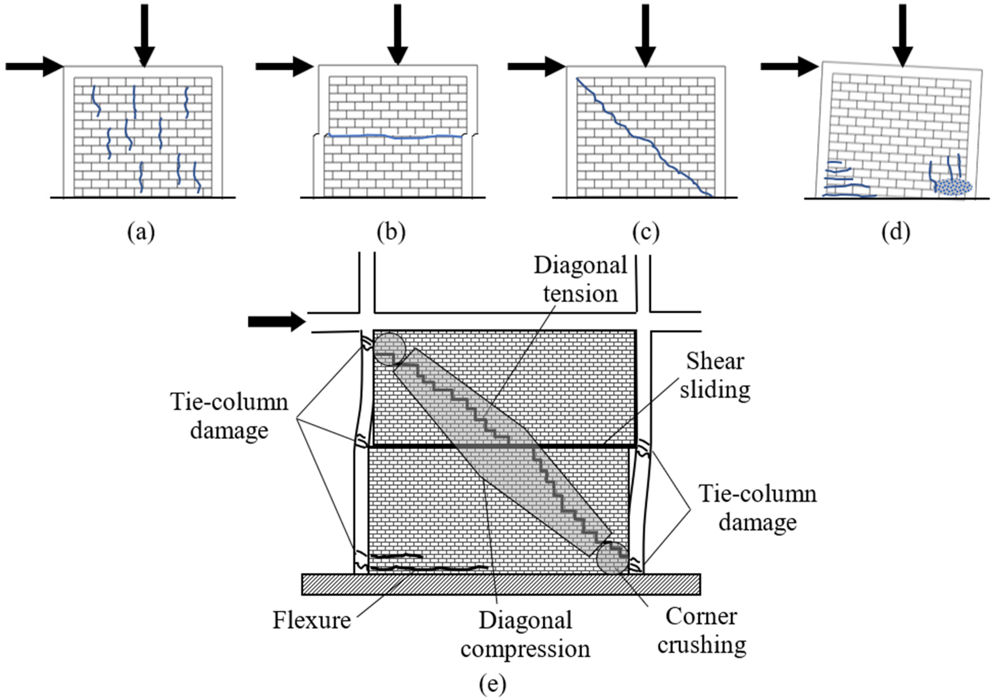
| In-plane | Compressive failure | Though crushing of the masonry is observed in almost all studies, compressive failure is not regarded as a major failure mode. |
| Sliding shear failure | Sliding shear failure has been observed in limited studies and mostly in CM walls that have a very low aspect ratio and low gravity loads, as reported by Yoshimura et al. [39,40], Kuroki et al. [41], Wijaya et al. [42], Gavilán et al. [43], etc. | |
| Diagonal tension failure | Formation of diagonal shear cracks resulting in the diagonal tension failure of the CM is the most common type of failure observed in past studies by Kato et al. [44], Aguilar et al. [45], Iiba et al. [46], Yoshimura et al. [39], Tomaževič and Klemenc [16], Yoshimura et al. [40], Kumazawa and Ohkubo [47], Yoshimura et al. [48], Yáñez et al. [49], Marinilli and Castilla [50], Zabala et al. [51], Gouveia and Lourenço [52], Bourzam et al. [12,13], Kuroki et al. [41], Wijaya et al. [42], Matošević et al. [53], Singhal et al. [35,36], Gavilán et al. [43], Gavilán [54], etc. | |
| Flexural cracks | Flexural failure is generally not observed in CM walls, but flexural cracks have been reported by Kato et al. [44], Iiba et al. [46], Yoshimura et al. [40,48], Zabala et al. [51], Gouveia and Lourenço [52], Matošević et al. [53], Varela-Rivera et al. [55], etc. | |
| Out-of-plane | Vertical/horizontal cracks | Out-of-plane failure is not generally observed in CM walls due to the confinement effects of RC tie-members. Some studies by Varela-Rivera et al. [56], Singhal et al. [35,36], etc., have reported vertical/horizontal cracks due to the out-of-plane response of CM walls. |
| Design Codes | Guidelines |
|---|---|
| Mexico: NTC-M: 2017 [117] | Meli et al. [7] |
| Peru: NT E.070: 2019 [118] | Schacher and Hart [59] |
| Chile: NCh2123: 2003 [119] | Brzev et al. [126] |
| Argentina: INPRES-CIRSOC 103: 2018 [120] | Carlevaro and Roux-Fouillet [127] |
| Colombia: NSR-98: 2010 [121] | Arya et al. [128] |
| Costa Rica: CSCR: 2000 [122] | Totten [129] |
| Europe: CEN: 2005 [123] | Boen and associates [130] |
| China: GB 50003: 2011 [124] | Schacher [131] |
| India: BIS: 2022 [125] | Blondet [132] |
Disclaimer/Publisher’s Note: The statements, opinions and data contained in all publications are solely those of the individual author(s) and contributor(s) and not of MDPI and/or the editor(s). MDPI and/or the editor(s) disclaim responsibility for any injury to people or property resulting from any ideas, methods, instructions or products referred to in the content. |
© 2023 by the authors. Licensee MDPI, Basel, Switzerland. This article is an open access article distributed under the terms and conditions of the Creative Commons Attribution (CC BY) license (https://creativecommons.org/licenses/by/4.0/).
Share and Cite
Borah, B.; Kaushik, H.B.; Singhal, V. Analysis and Design of Confined Masonry Structures: Review and Future Research Directions. Buildings 2023, 13, 1282. https://doi.org/10.3390/buildings13051282
Borah B, Kaushik HB, Singhal V. Analysis and Design of Confined Masonry Structures: Review and Future Research Directions. Buildings. 2023; 13(5):1282. https://doi.org/10.3390/buildings13051282
Chicago/Turabian StyleBorah, Bonisha, Hemant B. Kaushik, and Vaibhav Singhal. 2023. "Analysis and Design of Confined Masonry Structures: Review and Future Research Directions" Buildings 13, no. 5: 1282. https://doi.org/10.3390/buildings13051282