
Effect of a Novel Dowel and Cramp on the In-Plane Behavior of Multi-Leaf Stone Masonry Walls Proposed for Modern Masonry Buildings

Abstract
:1. Introduction
2. Materials and Methods
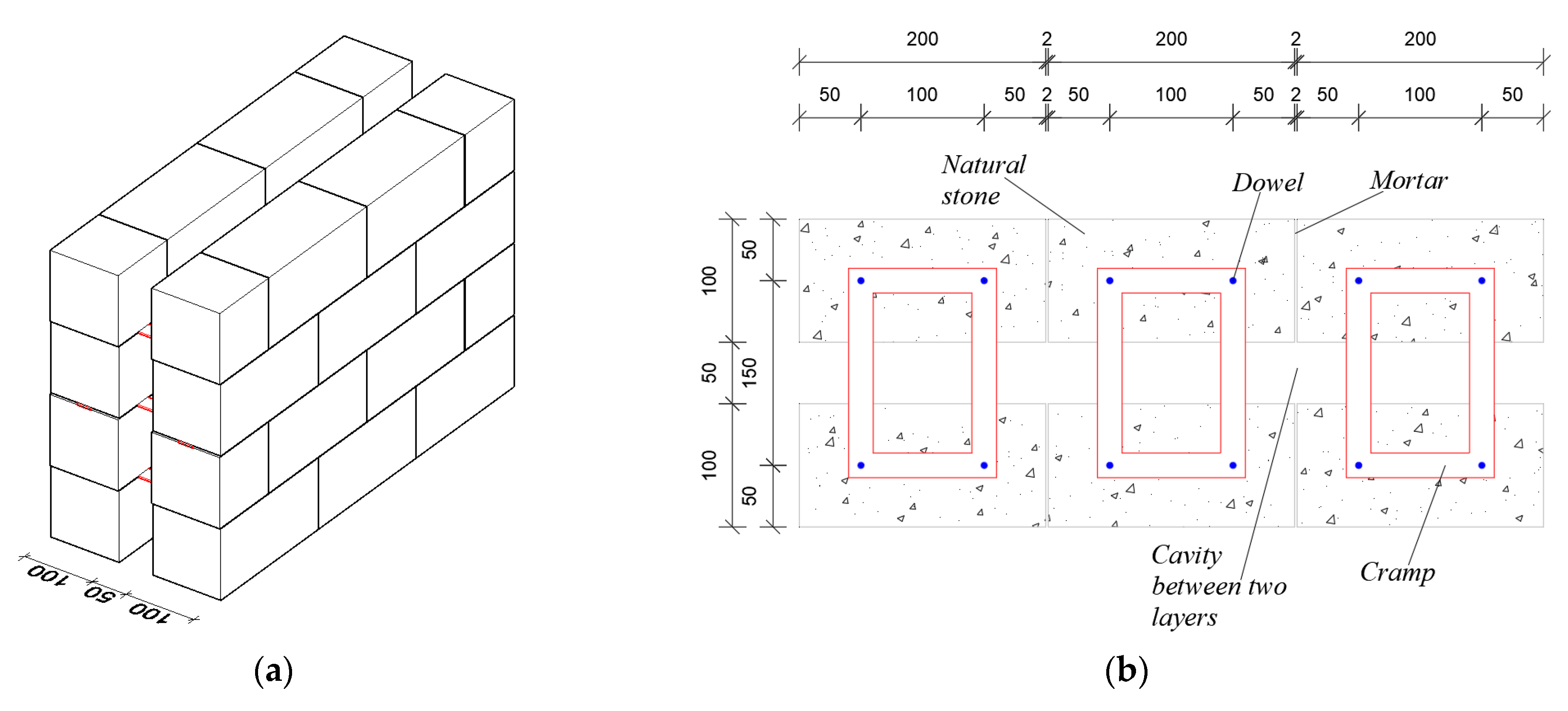
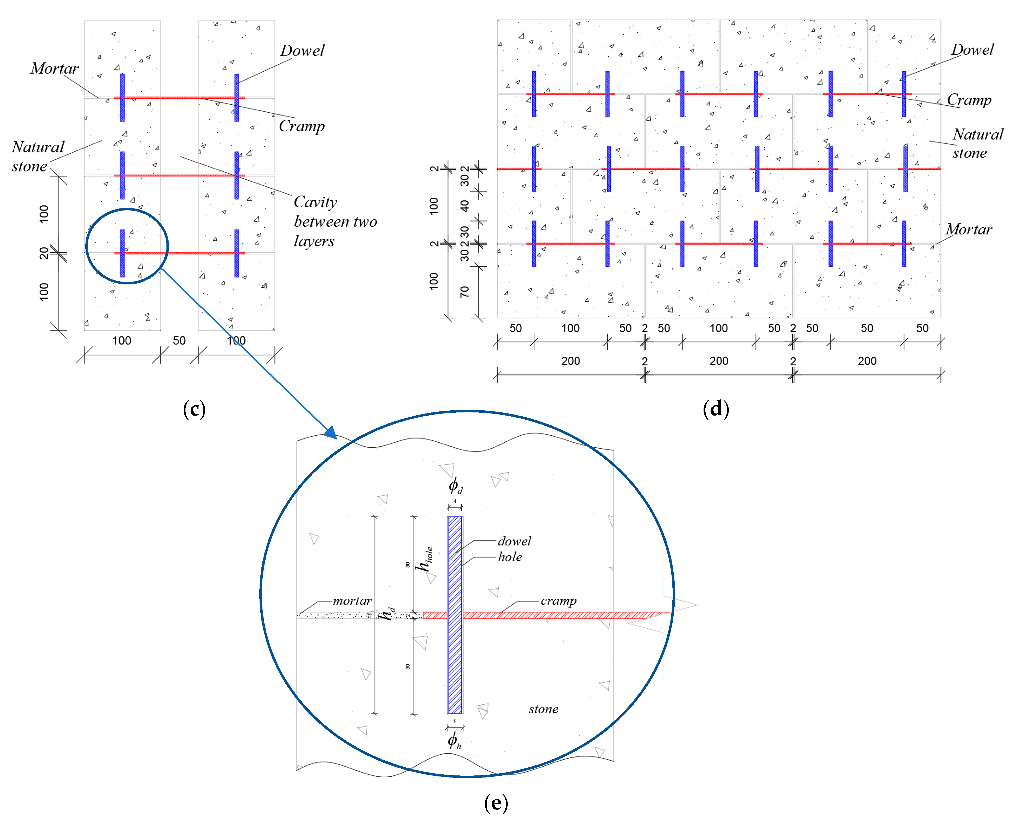
2.1. Proposed Wall
2.2. Properties of Materials
2.3. Experimental Program
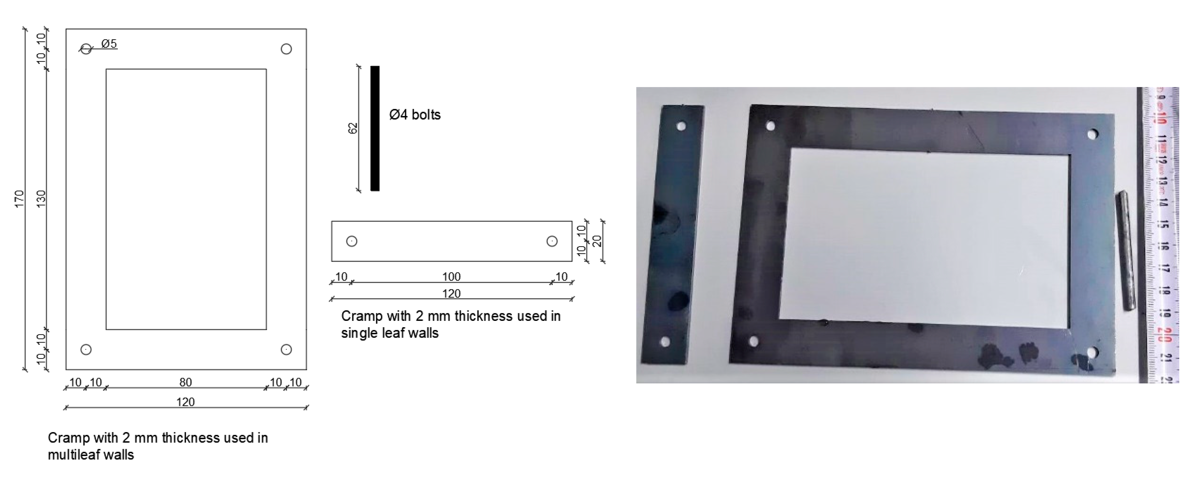
2.3.1. Metal Connectors
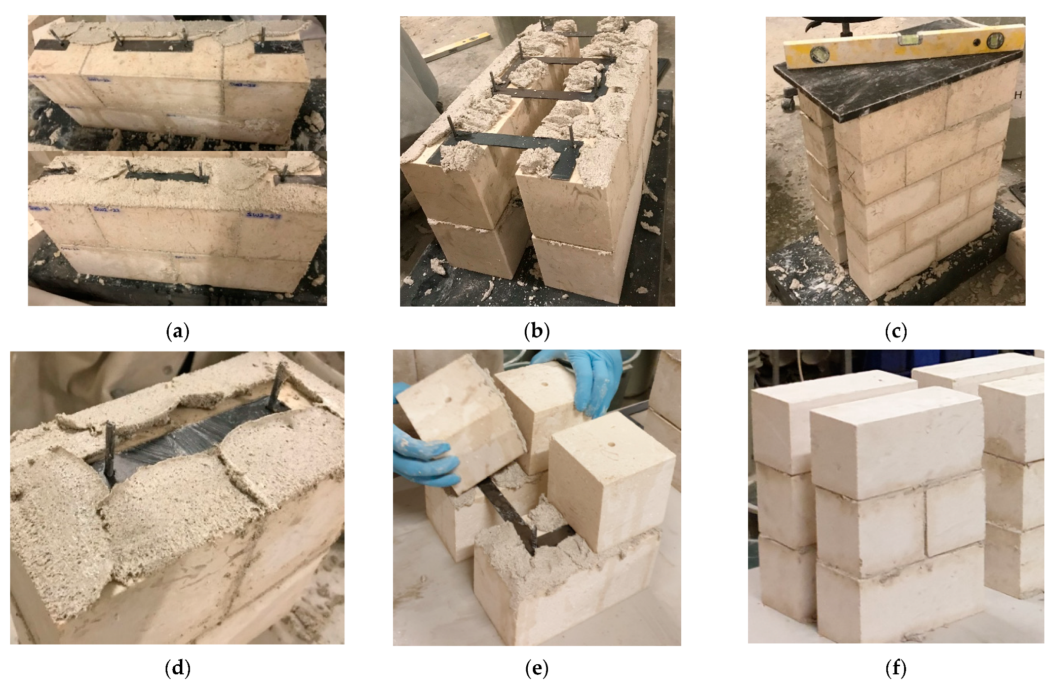
2.3.2. Test Specimens
- Micro-sized specimens
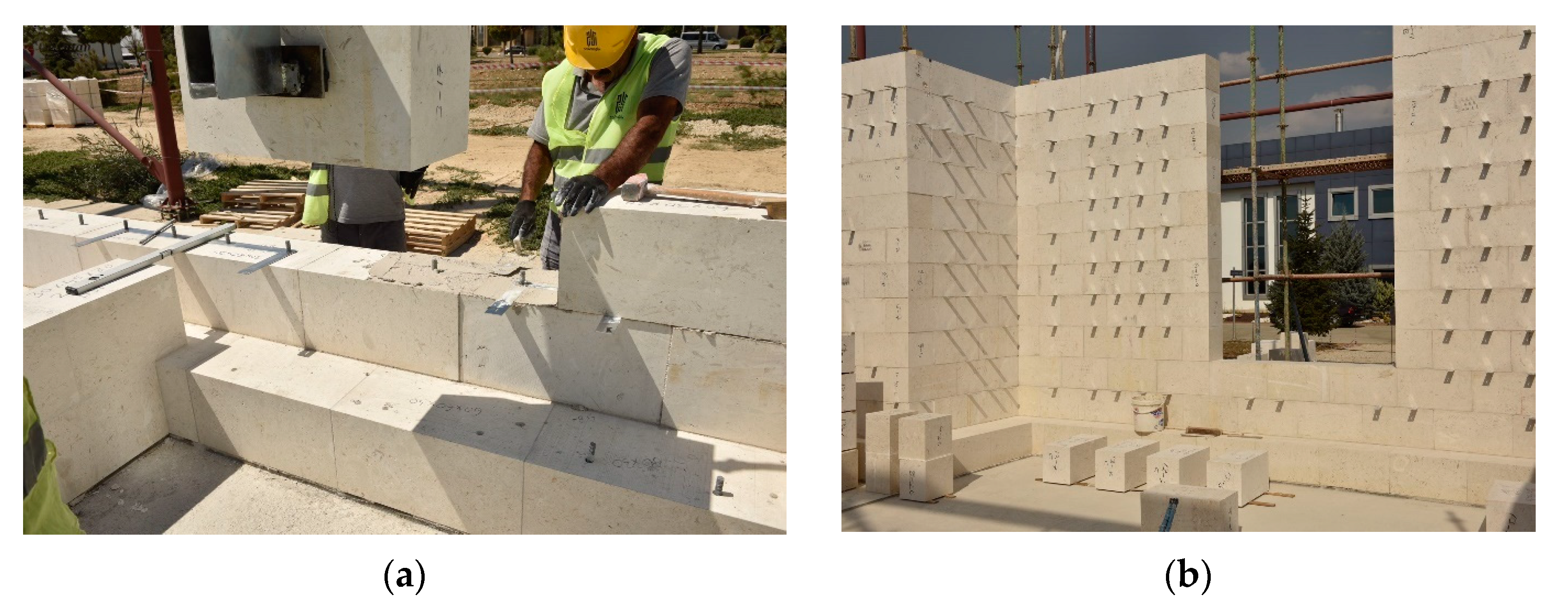
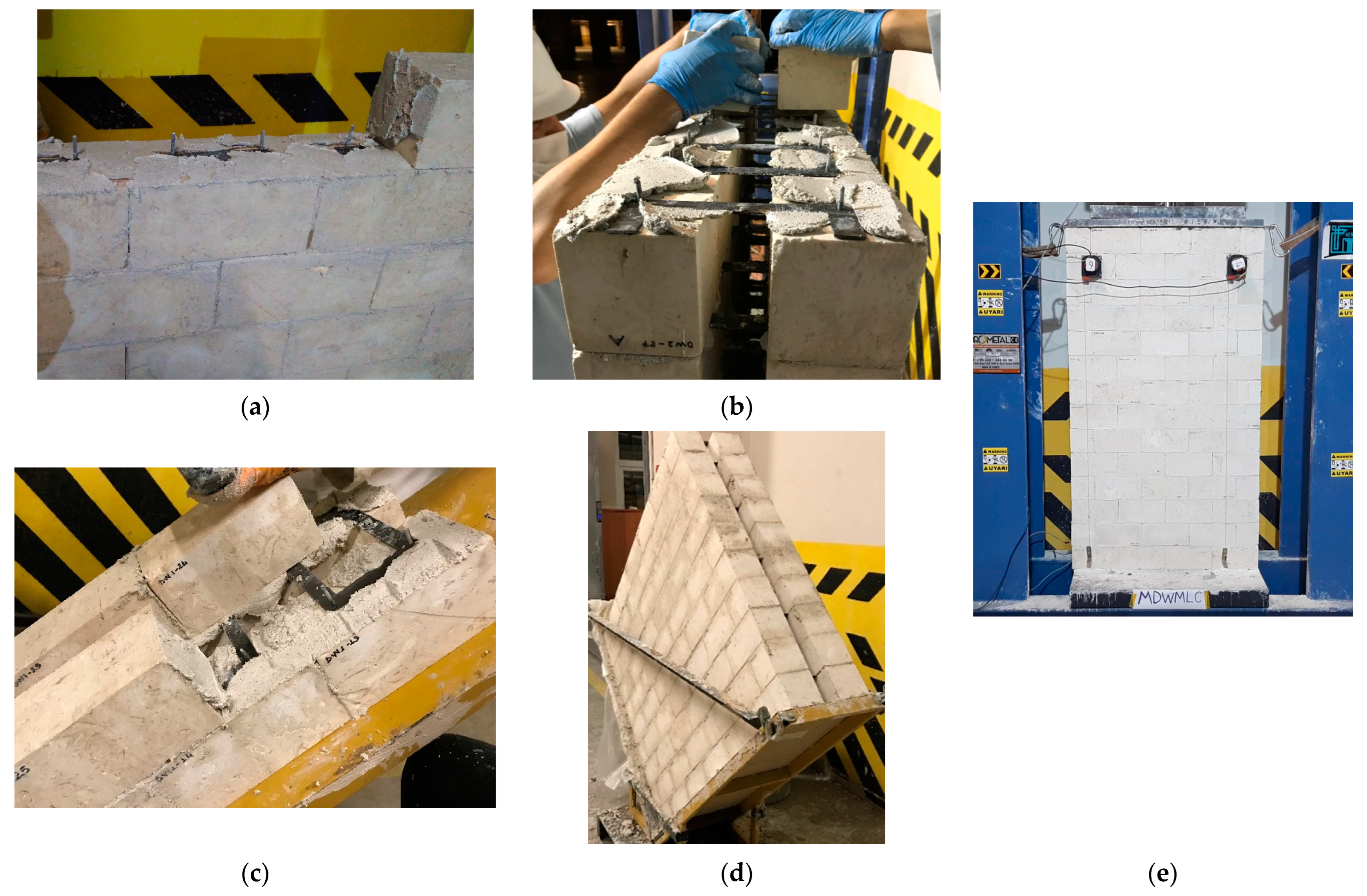
- Macro-sized specimens
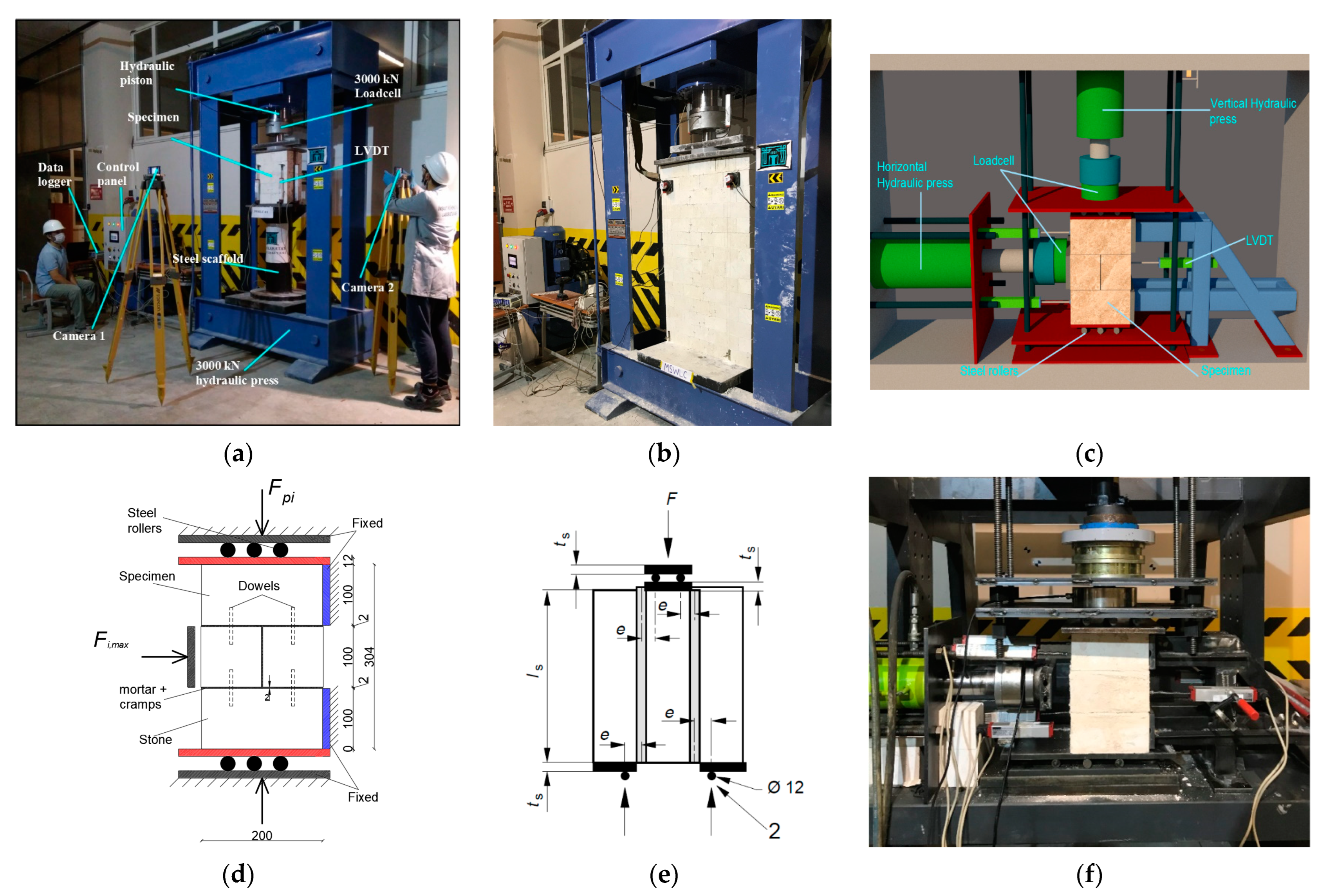
2.3.3. Experimental Setup
Compression Test
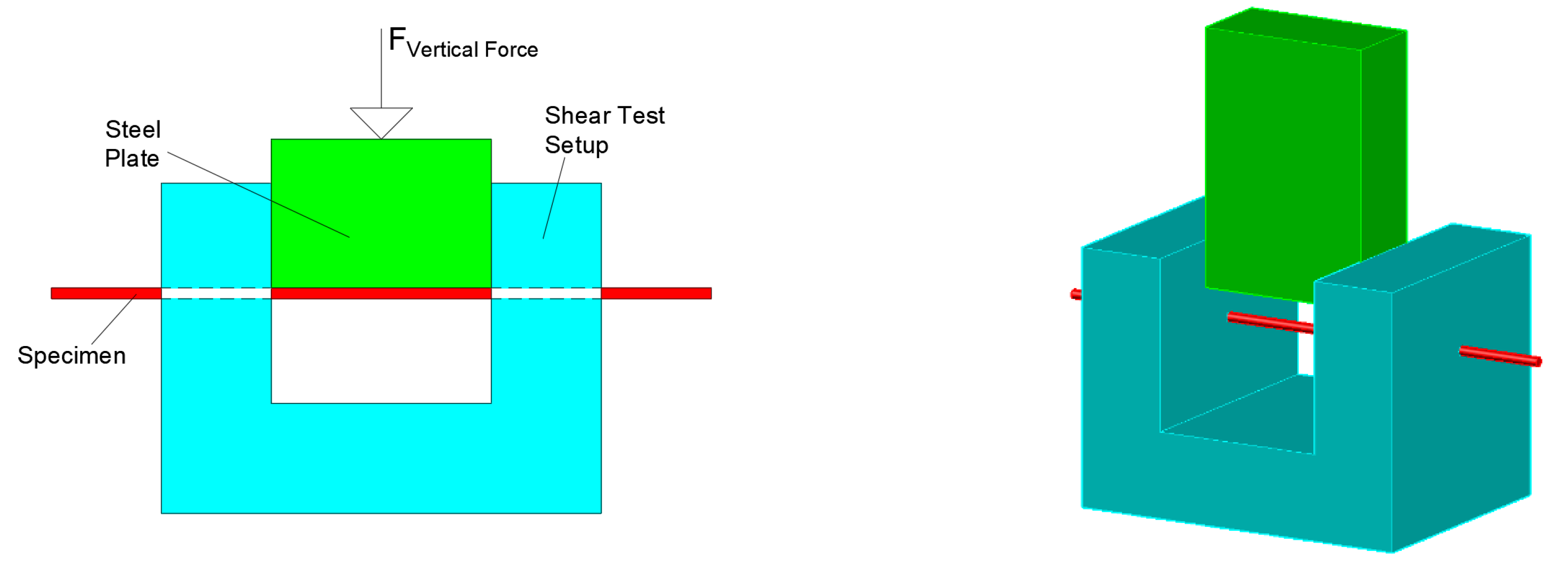
Triplet Test
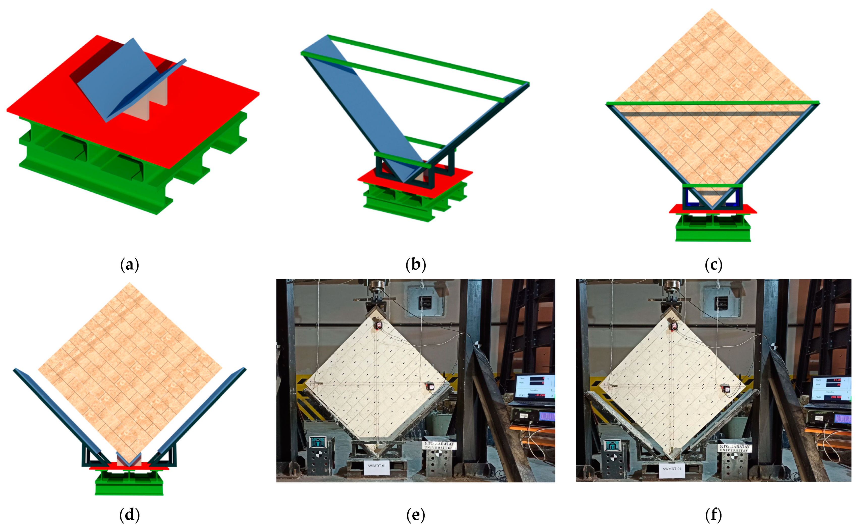
Diagonal Compression Test
3. Results
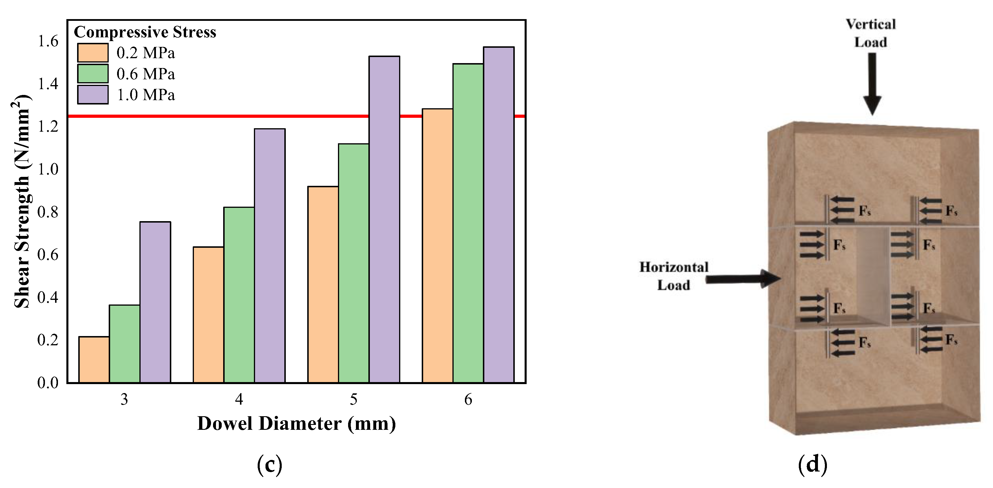
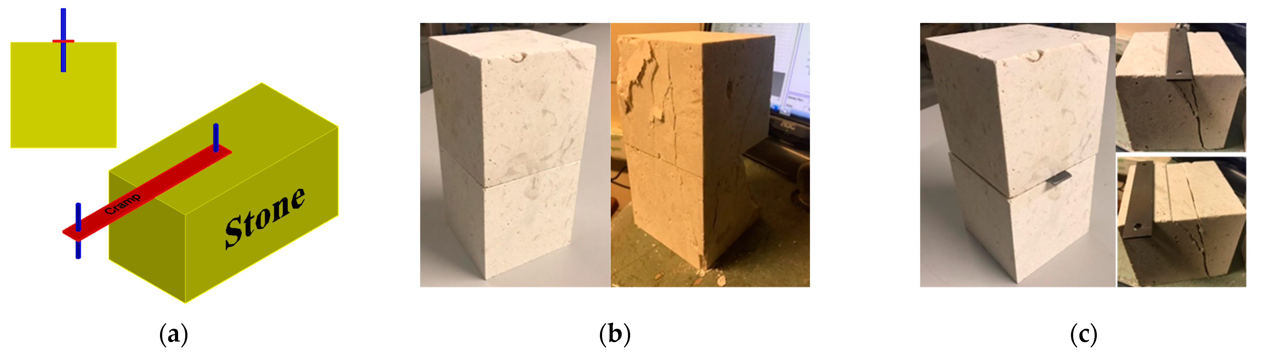
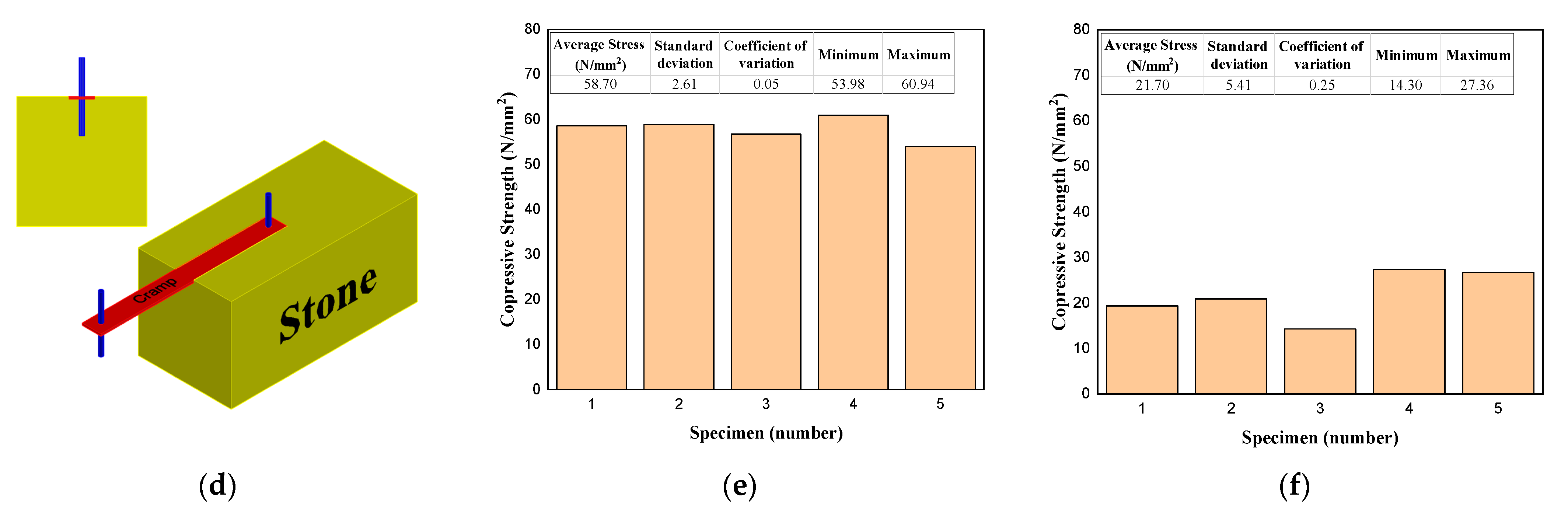
3.1. Optimum Dowel Diameter
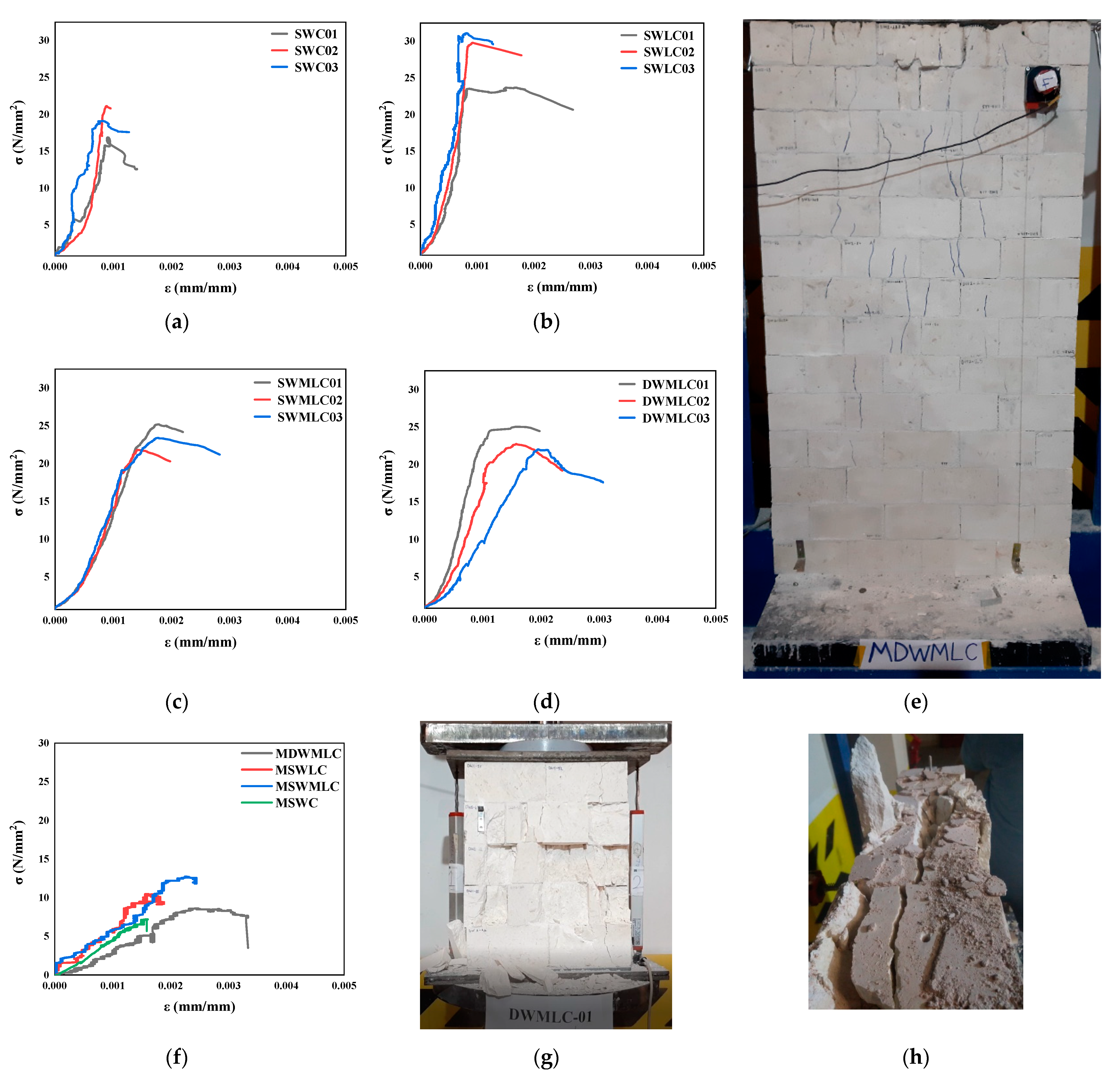
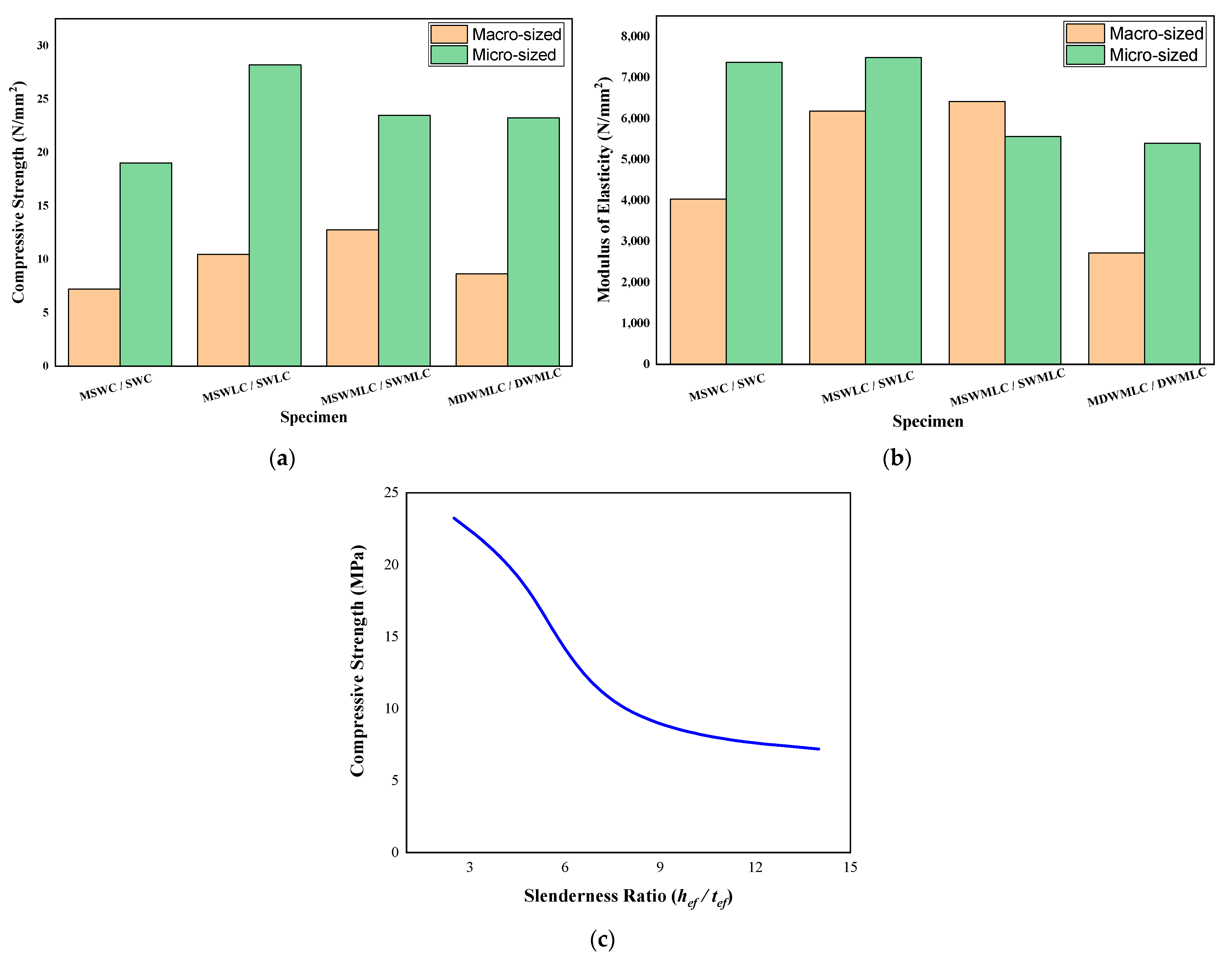
3.2. Compressive Strength
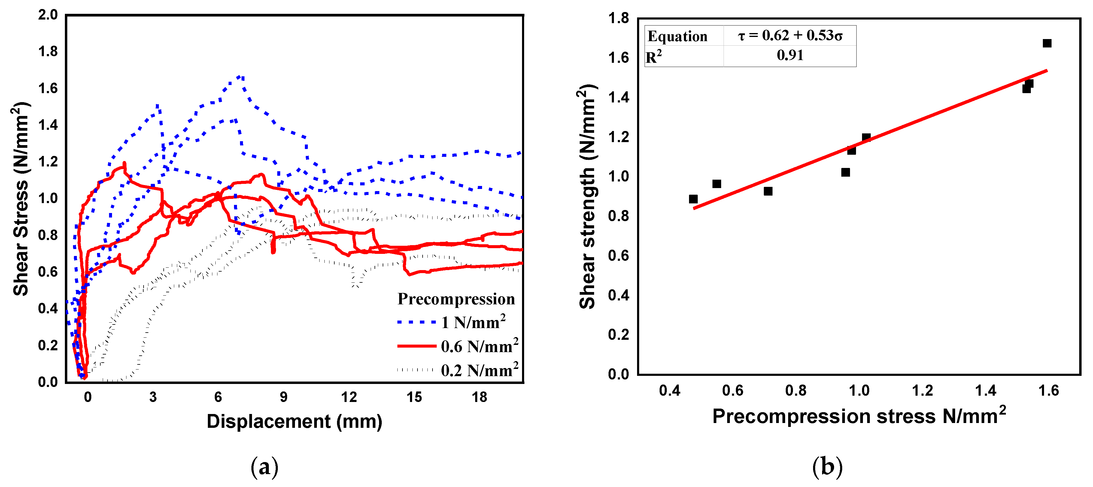
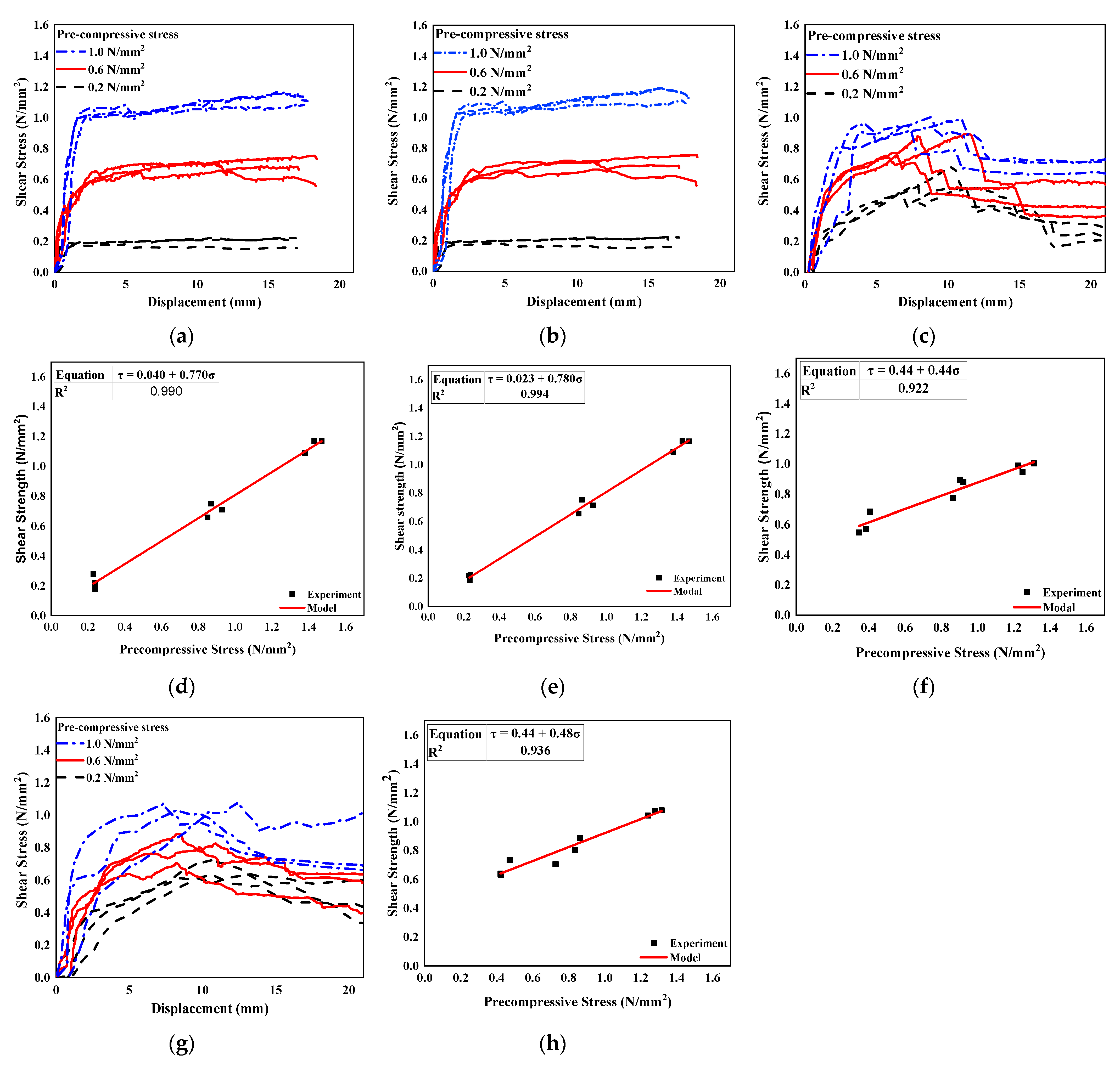
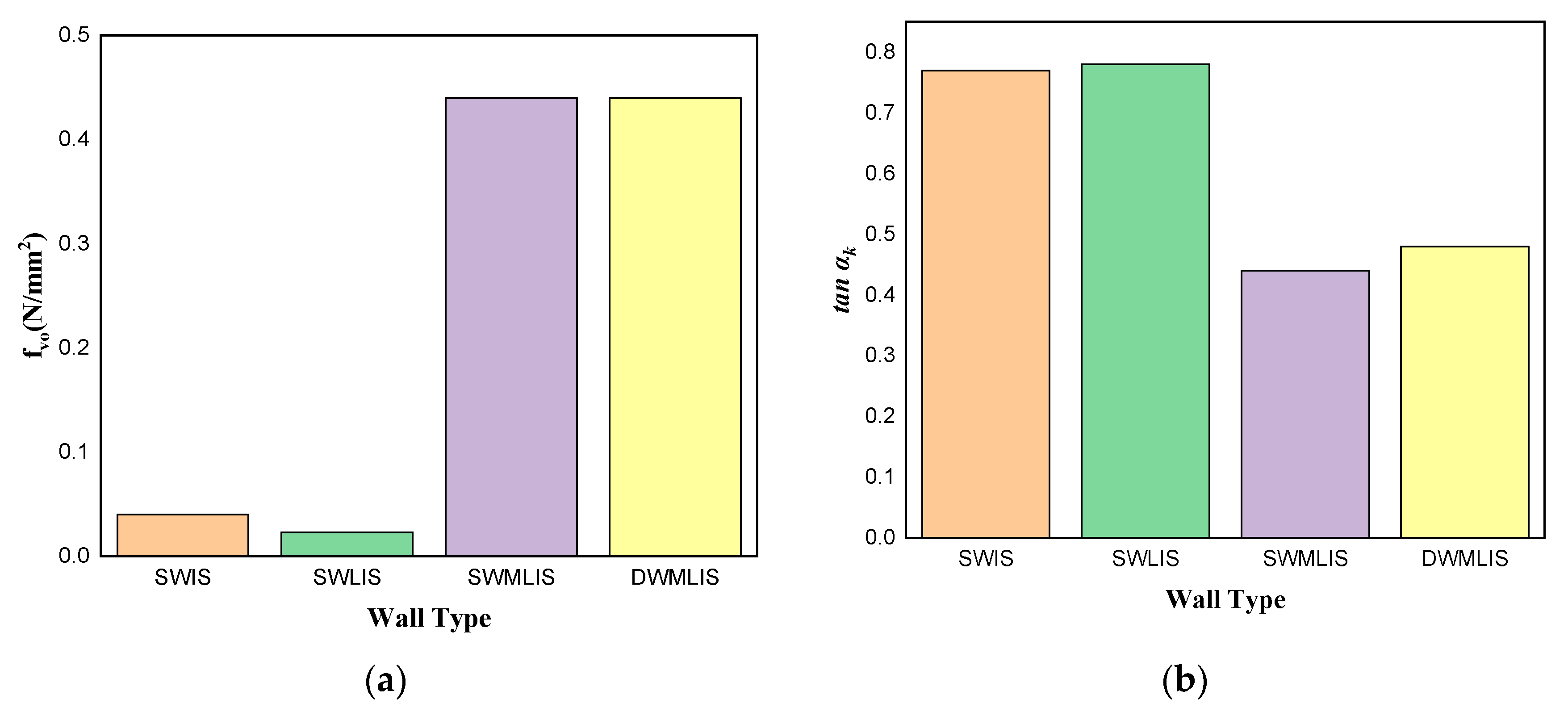
3.3. Triplet Test
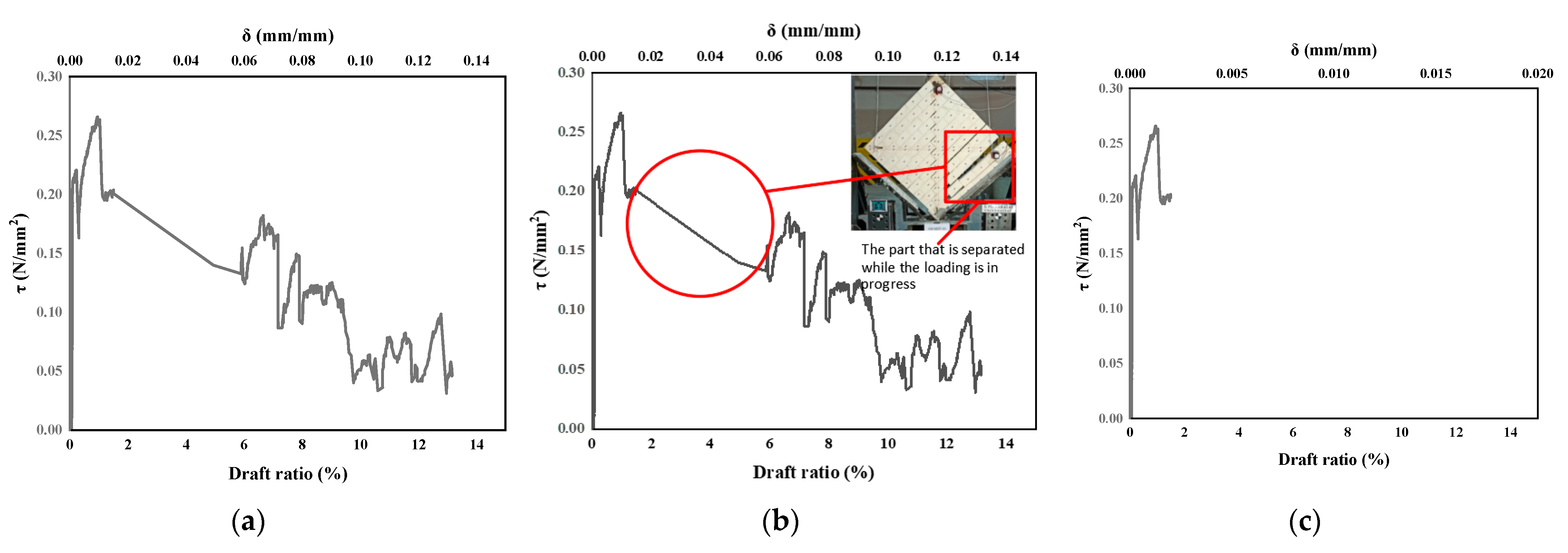
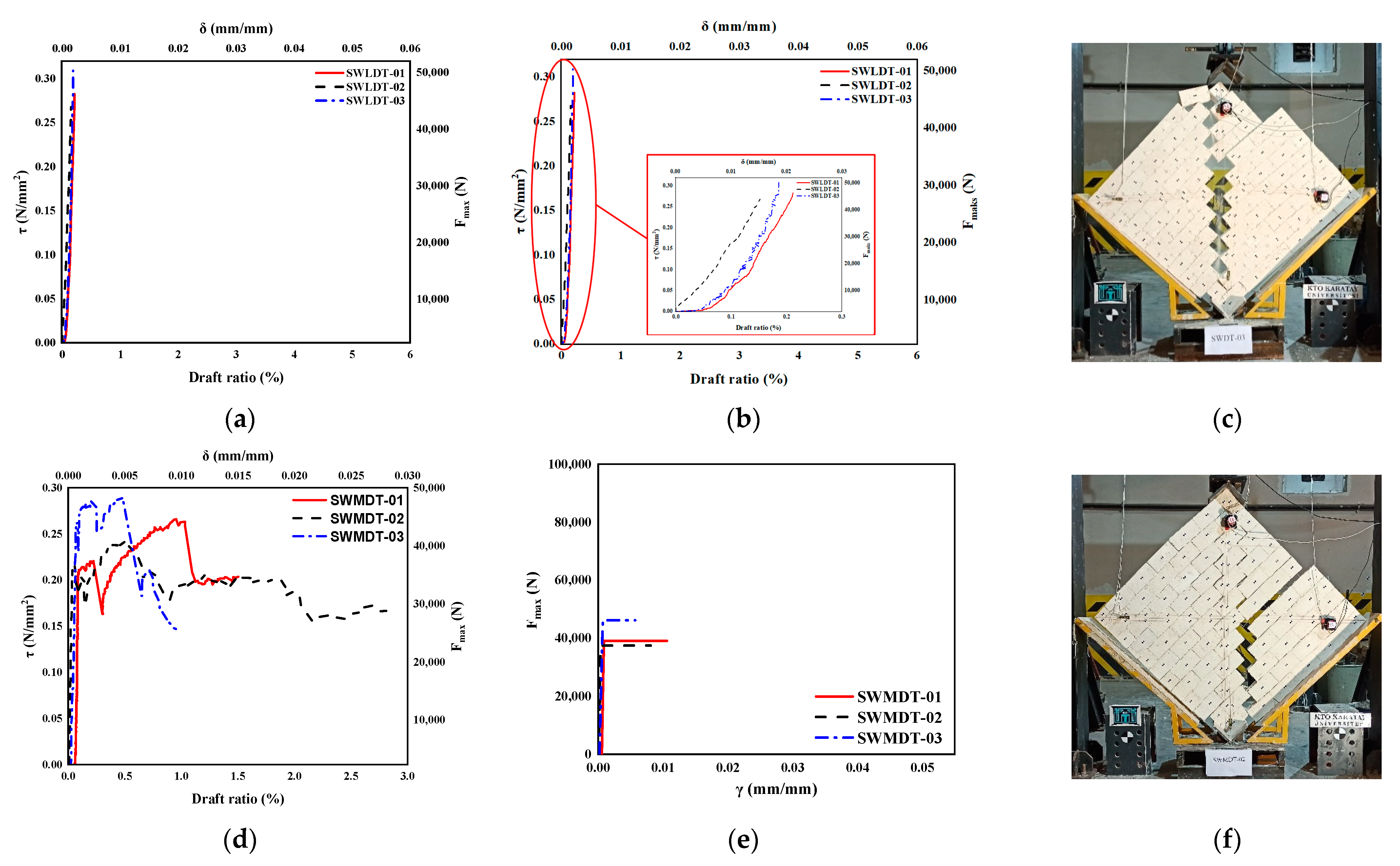
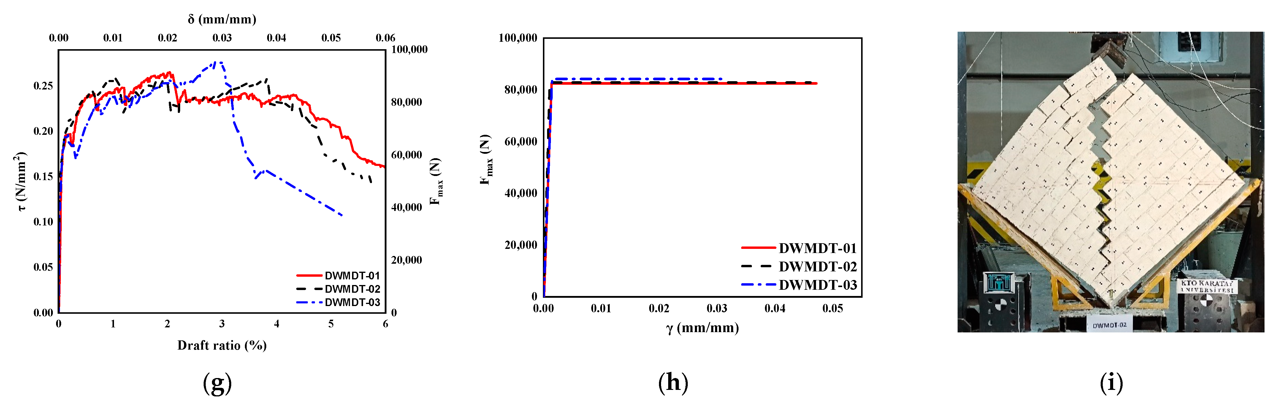
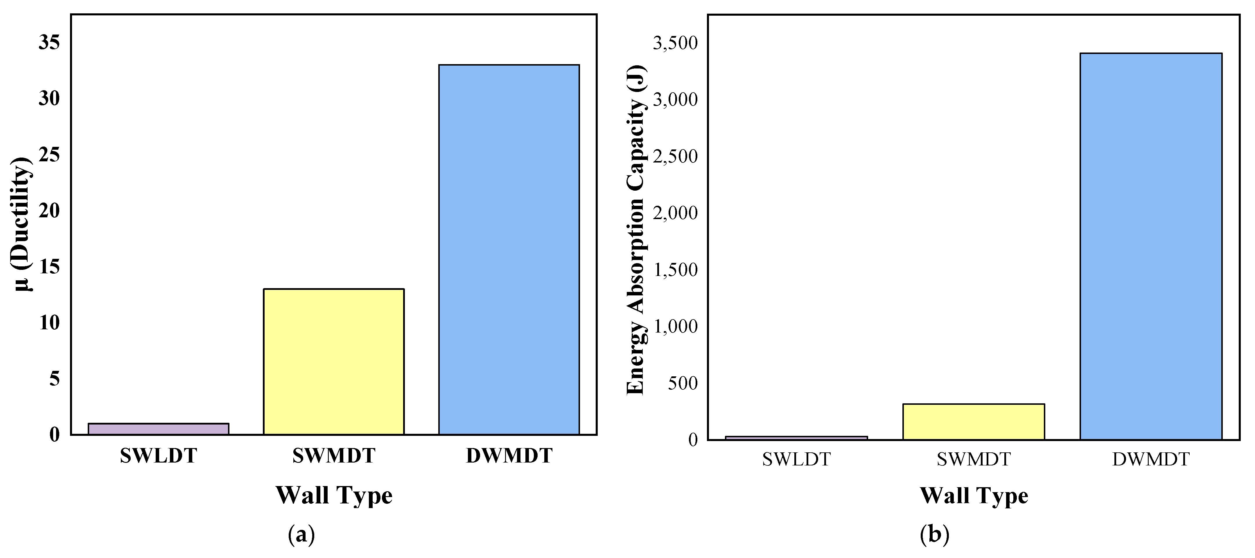
3.4. Diagonal Compression Test
4. Discussion
4.1. Compression
4.2. Shear
4.2.1. Triplet Test
4.2.2. Diagonal Compression Test
5. Conclusions
Author Contributions
Funding
Data Availability Statement
Acknowledgments
Conflicts of Interest
References
- Hendry, A.W.; Khalaf, F.M. Masonry Wall Construction; Spon Press: London, UK, 2001; Volume 39, ISBN 0415232821. [Google Scholar]
- Wright, G.R. Ancient Building Technology, 3rd ed.; Brill: Boston, MA, USA, 2009; ISBN 9783540773405. [Google Scholar]
- Jing, J.; Zhou, C.; Zhang, C.; Li, T. In-Plane Cyclic Behavior of Brick Walls Strengthened with CFRP Plates Embedded in the Horizontal Mortar Joint. J. Build. Eng. 2023, 63, 105476. [Google Scholar] [CrossRef]
- Gkournelos, P.D.; Triantafillou, T.C.; Bournas, D.A. Seismic Upgrading of Existing Masonry Structures: A State-of-the-Art Review. Soil Dyn. Earthq. Eng. 2022, 161, 107428. [Google Scholar] [CrossRef]
- Abdulsalam, B.; Ali, A.H.; ElSafty, A.; Elshafey, N. Behavior of GFRP Strengthening Masonry Walls Using Glass Fiber Composite Anchors. Structures 2021, 29, 1352–1361. [Google Scholar] [CrossRef]
- Anglade, E.; Giatreli, A.; Blyth, A.; Di, B.; Parisse, F.; Namourah, Z.; Rodrigues, H.; Miguel, T. International Journal of Disaster Risk Reduction Seismic Damage Scenarios for the Historic City Center of Leiria, Portugal: Analysis of the Impact of Different Seismic Retrofitting Strategies on Emergency Planning. Int. J. Disaster Risk Reduct. 2020, 44, 101432. [Google Scholar] [CrossRef]
- Rotunno, T.; Fagone, M.; Bertolesi, E.; Grande, E.; Milani, G. Curved Masonry Pillars Reinforced with Anchored CFRP Sheets: An Experimental Analysis. Compos. Part B 2019, 174, 107008. [Google Scholar] [CrossRef]
- Kumar, P.; Rao, V.; Singh, Y. Out-of-Plane Flexural Behaviour of Masonry Wallettes Strengthened Using FRP Composites and Externally Bonded Grids: Comparative Study. Compos. Part B 2019, 176, 107302. [Google Scholar] [CrossRef]
- Orlando, M.; Betti, M.; Spinelli, P. Assessment of Structural Behaviour and Seismic Retrofitting for an Italian Monumental Masonry Building. J. Build. Eng. 2020, 29, 101115. [Google Scholar] [CrossRef]
- Demir, C.; Ilki, A. Characterization of the Materials Used in the Multi-Leaf Masonry Walls of Monumental Structures in Istanbul, Turkey. Constr. Build. Mater. 2014, 64, 398–413. [Google Scholar] [CrossRef]
- García, D.; San-José, J.T.; Garmendia, L.; Larrinaga, P. Comparison between Experimental Values and Standards on Natural Stone Masonry Mechanical Properties. Constr. Build. Mater. 2012, 28, 444–449. [Google Scholar] [CrossRef]
- Oliveira, D.V.; Lourenço, P.B.; Roca, P. Cyclic Behaviour of Stone and Brick Masonry under Uniaxial Compressive Loading. Mater. Struct. 2006, 39, 247–257. [Google Scholar] [CrossRef]
- Buzov, A.; Radnić, J.; Grgić, N. Effects of Several Bolt Parameters on the Bearing Capacity of a Composite Multi-Drum Stone Column under an Earthquake. Compos. Part B Eng. 2019, 162, 250–258. [Google Scholar] [CrossRef]
- Muñoz, R.; Lourenço, P.B.; Moreira, S. Experimental Results on Mechanical Behaviour of Metal Anchors in Historic Stone Masonry. Constr. Build. Mater. 2018, 163, 643–655. [Google Scholar] [CrossRef]
- Vintzileou, E.; Miltiadou-Fezans, A. Mechanical Properties of Three-Leaf Stone Masonry Grouted with Ternary or Hydraulic Lime-Based Grouts. Eng. Struct. 2008, 30, 2265–2276. [Google Scholar] [CrossRef]
- Almeida, C.; Guedes, J.P.; Arêde, A.; Costa, C.Q.; Costa, A. Physical Characterization and Compression Tests of One Leaf Stone Masonry Walls. Constr. Build. Mater. 2012, 30, 188–197. [Google Scholar] [CrossRef]
- Silva, B.; Dalla Benetta, M.; Da Porto, F.; Modena, C. Experimental Assessment of In-Plane Behaviour of Three-Leaf Stone Masonry Walls. Constr. Build. Mater. 2014, 53, 149–161. [Google Scholar] [CrossRef]
- Gattesco, N.; Boem, I. Out-of-Plane Behavior of Reinforced Masonry Walls: Experimental and Numerical Study. Compos. Part B Eng. 2017, 128, 39–52. [Google Scholar] [CrossRef]
- Meimaroglou, N.; Mouzakis, H. Mechanical Properties of Three-Leaf Masonry Walls Constructed with Natural Stones and Mud Mortar. Eng. Struct. 2018, 172, 869–876. [Google Scholar] [CrossRef]
- Maccarini, H.; Vasconcelos, G.; Rodrigues, H.; Ortega, J.; Lourenço, P.B. Out-of-Plane Behavior of Stone Masonry Walls: Experimental and Numerical Analysis. Constr. Build. Mater. 2018, 179, 430–452. [Google Scholar] [CrossRef]
- Pulatsu, B.; Erdogmus, E.; Lourenço, P.B.; Lemos, J.V.; Tuncay, K. Simulation of the In-Plane Structural Behavior of Unreinforced Masonry Walls and Buildings Using DEM. Structures 2020, 27, 2274–2287. [Google Scholar] [CrossRef]
- Drougkas, A.; Roca, P.; Molins, C. Numerical Prediction of the Behavior, Strength and Elasticity of Masonry in Compression. Eng. Struct. 2015, 90, 15–28. [Google Scholar] [CrossRef]
- Andreotti, G.; Graziotti, F.; Magenes, G. Detailed Micro-Modelling of the Direct Shear Tests of Brick Masonry Specimens: The Role of Dilatancy. Eng. Struct. 2018, 168, 929–949. [Google Scholar] [CrossRef]
- Juhásová, E.; Sofronie, R.; Bairrão, R. Stone Masonry in Historical Buildings-Ways to Increase Their Resistance and Durability. Eng. Struct. 2008, 30, 2194–2205. [Google Scholar] [CrossRef]
- Silva, M.B. Percepção Da População Assistida Sobre a Inserção de Estudantes de Medicina Na Unidade Básica de Saúde. Trab. Conclusão Curso 2016, 1, 1–10. [Google Scholar] [CrossRef]
- Acito, M.; Magrinelli, E.; Milani, G.; Tiberti, S. Seismic Vulnerability of Masonry Buildings: Numerical Insight on Damage Causes for Residential Buildings by the 2016 Central Italy Seismic Sequence and Evaluation of Strengthening Techniques. J. Build. Eng. 2020, 28, 101081. [Google Scholar] [CrossRef]
- EN 1052-3; Methods of Test for Masonry-Part 3: Determination of Initial Shear Strength. Comitee Europeen de Normalisation: Brussels, Belgium, 2002.
- ASTM E 519M-15; Standard Test Method for Diagonal Tension (Shear) in Masonry Assemblages. ASTM International: West Conshohocken, PA, USA, 2015.
- EN 1052-1; Methods of Test for Masonry-Part 1: Determination of Compressive Strength. Comitee Europeen de Normalisation: Brussels, Belgium, 1999.
- Boscato, G.; Reccia, E.; Cecchi, A. Non-Destructive Experimentation: Dynamic Identification of Multi-Leaf Masonry Walls Damaged and Consolidated. Compos. Part B Eng. 2018, 133, 145–165. [Google Scholar] [CrossRef]
- Borri, A.; Corradi, M.; Castori, G.; Molinari, A. Stainless Steel Strip–A Proposed Shear Reinforcement for Masonry Wall Panels. Constr. Build. Mater. 2019, 211, 594–604. [Google Scholar] [CrossRef]
- Cotič, P.; Jagličić, Z.; Bosiljkov, V. Validation of Non-Destructive Characterization of the Structure and Seismic Damage Propagation of Plaster and Texture in Multi-Leaf Stone Masonry Walls of Cultural-Artistic Value. J. Cult. Herit. 2014, 15, 490–498. [Google Scholar] [CrossRef]
- Cascardi, A.; Leone, M.; Aiello, M.A. Transversal Joining of Multi-Leaf Masonry through Different Types of Connector: Experimental and Theoretical Investigation. Constr. Build. Mater. 2020, 265, 120733. [Google Scholar] [CrossRef]
- Rezaie, A.; Godio, M.; Beyer, K. Experimental Investigation of Strength, Stiffness and Drift Capacity of Rubble Stone Masonry Walls. Constr. Build. Mater. 2020, 251, 118972. [Google Scholar] [CrossRef]
- Tiberti, S.; Milani, G. 3D Homogenized Limit Analysis of Non-Periodic Multi-Leaf Masonry Walls. Comput. Struct. 2020, 234, 106253. [Google Scholar] [CrossRef]
- Graziotti, F.; Tomassetti, U.; Penna, A.; Magenes, G. Out-of-Plane Shaking Table Tests on URM Single Leaf and Cavity Walls. Eng. Struct. 2016, 125, 455–470. [Google Scholar] [CrossRef]
- Tomassetti, U.; Graziotti, F.; Penna, A.; Magenes, G. Modelling One-Way out-of-Plane Response of Single-Leaf and Cavity Walls. Eng. Struct. 2018, 167, 241–255. [Google Scholar] [CrossRef]
- Arslan, O.; Messali, F.; Smyrou, E.; Bal, İ.E.; Rots, J.G. Experimental Characterization of the Axial Behavior of Traditional Masonry Wall Metal Tie Connections in Cavity Walls. Constr. Build. Mater. 2020, 266, 121141. [Google Scholar] [CrossRef]
- Giaretton, M.; Dizhur, D.; da Porto, F.; Ingham, J.M. Construction Details and Observed Earthquake Performance of Unreinforced Clay Brick Masonry Cavity-Walls. Structures 2016, 6, 159–169. [Google Scholar] [CrossRef]
- Derakhshan, H.; Lucas, W.; Visintin, P.; Griffith, M.C. Out-of-Plane Strength of Existing Two-Way Spanning Solid and Cavity Unreinforced Masonry Walls. Structures 2018, 13, 88–101. [Google Scholar] [CrossRef]
- Xiao, J.; Pu, J.; Hu, Y. Experimental Study on the Compressive Performance of New Sandwich Masonry Walls. Front. Struct. Civ. Eng. 2013, 7, 154–163. [Google Scholar] [CrossRef]
- Corradi, M.; Borri, A.; Poverello, E.; Castori, G. The Use of Transverse Connectors as Reinforcement of Multi-Leaf Walls. Mater. Struct. 2017, 50, 114. [Google Scholar] [CrossRef]
- EN 1926; Natural Stone Test Methods—Determination of Uniaxial Compressive Strength. European Committee for Standardization: Brussels, Belgium, 2006.
- EN 12372; Natural Stone Test Methods—Determination of Flexural Strength under Concentrated Load. European Committee for Standardization: Brussels, Belgium, 2006.
- EN 14580; Natural Stone Test Methods—Determination of Static Elastic Modulus. European Committee for Standardization: Brussels, Belgium, 2006; Volume 3, p. 15.
- Isabel, A.; Morais, J.; Morais, P.; Veiga, R.; Santos, C.; Candeias, P.; Gomes, J. Modulus of Elasticity of Mortars: Static and Dynamic Analyses. Constr. Build. Mater. 2020, 232, 117216. [Google Scholar]
- Oliveira, D.V.; Silva, R.A.; Garbin, E.; Lourenço, P.B. Strengthening of Three-Leaf Stone Masonry Walls: An Experimental Research. Mater. Struct. 2012, 45, 1259–1276. [Google Scholar] [CrossRef]
- Milosevic, J.; Gago, A.S.; Lopes, M.; Bento, R. Experimental Assessment of Shear Strength Parameters on Rubble Stone Masonry Specimens. Constr. Build. Mater. 2013, 47, 1372–1380. [Google Scholar] [CrossRef]
- EN 1015-11; Methods of Test for Mortar for Masonry-Part 11: Determination of Flexural and Compressive Strength of Hardened Mortar. European Committee for Standardization: Brussels, Belgium, 2006; Volume 3.
- TS EN ISO 6892-1; Metallic Materials—Tensile Testing—Part 1: Method of Test at Room Temperature. Turkish Standard: Ankara, Türkiye, 2016.
- Demir, C. Seismic Behaviour of Historical Stone Masonry Multi-Leaf Walls. Ph.D. Thesis, İstanbul Teknik Üniversitesi, Fen Bilimleri Enstitüsü, İstanbul, 2012. [Google Scholar]
- Van der Pluijm, R. Out-of-Plane Bending of Masonry: Behaviour and Strength, Doktora tezi; Eindhoven Teknoloji Üniversitesi: Eindhoven, The Netherlands, 1999. [Google Scholar]
- Liu, P.F.; Li, H.N.; Li, G.; Ansari, F.; Li, C. Out-of-Plane Seismic Behavior of Cast-in-Situ Composite Wall with Metal Tailing Porous Concrete. Eng. Struct. 2020, 210, 110346. [Google Scholar] [CrossRef]
- Türkmen, S.; Wijte, S.N.M.; De Vries, B.T.; Ingham, J.M. Out-of-Plane Behavior of Clay Brick Masonry Walls Retrofitted with Flexible Deep Mounted CFRP Strips. Eng. Struct. 2021, 228, 111448. [Google Scholar] [CrossRef]
- Petry, S.; Beyer, K. Scaling Unreinforced Masonry for Reduced-Scale Seismic Testing. Bull. Earthq. Eng. 2014, 12, 2557–2581. [Google Scholar] [CrossRef]
- Parisi, F.; Balestrieri, C.; Asprone, D. Nonlinear Micromechanical Model for Tuff Stone Masonry: Experimental Validation and Performance Limit States. Constr. Build. Mater. 2016, 105, 165–175. [Google Scholar] [CrossRef]
- Guadagnuolo, M.; Aurilio, M.; Basile, A.; Faella, G. Modulus of Elasticity and Compressive Strength of Tuff Masonry: Results of a Wide Set of Flat-Jack Tests. Buildings 2020, 10, 84. [Google Scholar] [CrossRef]
- Veríssimo-Anacleto, J.; Ludovico-Marques, M.; Neto, P. An Empirical Model for Compressive Strength of the Limestone Masonry Based on Number of Courses–An Experimental Study. Constr. Build. Mater. 2020, 258, 119508. [Google Scholar] [CrossRef]
- Garcia-Ramonda, L.; Pelá, L.; Roca, P.; Camata, G. In-Plane Shear Behaviour by Diagonal Compression Testing of Brick Masonry Walls Strengthened with Basalt and Steel Textile Reinforced Mortars. Constr. Build. Mater. 2020, 240, 116752. [Google Scholar] [CrossRef]
- Harris, K.A.; Sharma, B. Nonconventional and Vernacular Construction Materials; Woodhead Publishing: Duxford, UK, 2016; ISBN 9781782423058. [Google Scholar]
- Comitee Europeen de Normalisation. European Committee for Standardization (CEN) Eurocode 6: Design of Masonry Structures—Part 2: Design, Selection of Materials and Execution of Masonry; Comitee Europeen de Normalisation: Brussels, Belgium, 2001; pp. 1–70. [Google Scholar]
- Binda, L.; Pina-Henriques, J.; Anzani, A.; Fontana, A.; Lourenço, P.B. A Contribution for the Understanding of Load-Transfer Mechanisms in Multi-Leaf Masonry Walls: Testing and Modelling. Eng. Struct. 2006, 28, 1132–1148. [Google Scholar] [CrossRef]
- Silva, R.A.; Oliveira, D.V.; Lourenço, P.B. On the Strengthening of Three-Leaf Stone Masonry Walls. In Proceedings of the Structural Analysis of Historic Construction: Preserving Safety and Significance, Bath, UK, 2–4 July 2008; Volume 2, pp. 739–746. [Google Scholar]


| Material | fi (N/mm2) | ftc (N/mm2) | Fy (N/mm2) | Fu (N/mm2) | E (GPa) | Fτ (N/mm2) |
|---|---|---|---|---|---|---|
| Stone | 50 | 12.2 | - | - | 15 | - |
| Mortar | 1.46 | 0 | - | - | - | - |
| Cramps | - | - | 227 | 330 | 114 | - |
| Dowels | - | - | 61 | 602 | 31 |
| Code Name | Test Setup | Number of Layers | Metal Connectors | Mortar | Number of Specimens | Specimen Size (mm) (Width × Length × Height) |
|---|---|---|---|---|---|---|
| SWC | Compression | Single | No | No | 3 | 100 × 400 × 500 |
| SWLC | Compression | Single | No | Yes | 3 | 100 × 402 × 508 |
| SWMLC | Compression | Single | Yes | Yes | 3 | 100 × 402 × 508 |
| DWMLC | Compression | Double | Yes | Yes | 3 | 200 × 402 × 508 |
| SWIS | Initial Shear | Single | No | No | 9 | 100 × 200 × 300 |
| SWLIS | Initial Shear | Single | No | Yes | 9 | 100 × 202 × 304 |
| SWMLIS | Initial Shear | Single | Yes | Yes | 9 | 100 × 202 × 304 |
| DWMLIS | Initial Shear | Double | Yes | Yes | 9 | 200 × 202 × 304 |
| Code Name | Number of Layers | Metal Connectors | Mortar | Number of Specimens | Specimen Size (mm) (Width × Length × Height) |
|---|---|---|---|---|---|
| MSWC | Single | No | No | 1 | 100 × 800 × 1400 |
| MSWLC | Single | No | Yes | 1 | 100 × 806 × 1426 |
| MSWMLC | Single | Yes | Yes | 1 | 100 × 806 × 1426 |
| MDWMLC | Double | Yes | Yes | 1 | 200 × 806 × 1426 |
| SWDT | Single | No | Yes | 3 | 100 × 1210 × 1222 |
| SWMDT | Single | Yes | Yes | 3 | 100 × 1210 × 1222 |
| DWMDT | Double | Yes | Yes | 3 | 200 × 1210 × 1222 |
| Specimen | Specimen Size | fi (N/mm2) | E (N/mm2) |
|---|---|---|---|
| SWC | Micro-sized | 19.02 | 7369 |
| SWLC | 28.19 | 7490 | |
| SWMLC | 23.47 | 5558 | |
| DWMLC | 23.24 | 5394 | |
| MSWC | Macro-sized | 7.20 | 4030 |
| MSWLC | 10.46 | 6177 | |
| MSWMLC | 12.74 | 6416 | |
| MDWMLC | 8.63 | 2716 |
| Specimen Code | Stan. Comp. 1 Stress (N/mm2) | Avg. Appl. 2 Comp. Stress (N/mm2) | Avg. Shear Force (N) | Avg. Shear Stress (N/mm2) |
|---|---|---|---|---|
| SWIS20 | 0.2 | 0.24 | 7840 | 0.23 |
| SWIS60 | 0.6 | 0.88 | 26,881 | 0.71 |
| SWIS100 | 1.0 | 1.43 | 43,091 | 1.17 |
| SWMLIS20 | 0.2 | 0.38 | 22,829 | 0.6 |
| SWMLIS60 | 0.6 | 0.90 | 32,523 | 0.85 |
| SWMLIS100 | 1.0 | 1.26 | 37,438 | 0.98 |
| DWMLIS20 | 0.2 | 0.44 | 50,399 | 0.67 |
| DWMLIS60 | 0.6 | 0.81 | 61,076 | 0.80 |
| DWMLIS100 | 1.0 | 1.28 | 81,052 | 1.06 |
| Specimens | Fmax (N) | Avg. Fmax (N) | τ (N/mm2) | Avg. τ (N/mm2) | γu | γy | μ | Avg. μ | Avg. G |
|---|---|---|---|---|---|---|---|---|---|
| SWLDT-01 | 47,953 | 48,955 | 0.28 | 2.29 | 0.00190 | 0.00190 | 1 | 1 | 118 |
| SWLDT-02 | 46,449 | 0.27 | 0.00188 | 0.00188 | 1 | ||||
| SWLDT-03 | 52,463 | 0.31 | 0.00090 | 0.00090 | 1 | ||||
| SWMDT-01 | 46,165 | 45,975 | 0.27 | 0.27 | 0.00100 | 0.01060 | 11 | 13 | 366 |
| SWMDT-02 | 41,898 | 0.24 | 0.00041 | 0.00811 | 20 | ||||
| SWMDT-03 | 49,863 | 0.29 | 0.00078 | 0.00571 | 7 | ||||
| DWMDT-01 | 91,760 | 92,709 | 0.27 | 0.27 | 0.00139 | 0.04715 | 34 | 33 | 186 |
| DWMDT-02 | 89,850 | 0.26 | 0.00108 | 0.04615 | 43 | ||||
| DWMDT-03 | 96,515 | 0.28 | 0.00148 | 0.03180 | 22 |
Disclaimer/Publisher’s Note: The statements, opinions and data contained in all publications are solely those of the individual author(s) and contributor(s) and not of MDPI and/or the editor(s). MDPI and/or the editor(s) disclaim responsibility for any injury to people or property resulting from any ideas, methods, instructions or products referred to in the content. |
© 2023 by the authors. Licensee MDPI, Basel, Switzerland. This article is an open access article distributed under the terms and conditions of the Creative Commons Attribution (CC BY) license (https://creativecommons.org/licenses/by/4.0/).
Share and Cite
Ziya, A.C.; İlgün, A. Effect of a Novel Dowel and Cramp on the In-Plane Behavior of Multi-Leaf Stone Masonry Walls Proposed for Modern Masonry Buildings. Buildings 2023, 13, 1235. https://doi.org/10.3390/buildings13051235
Ziya AC, İlgün A. Effect of a Novel Dowel and Cramp on the In-Plane Behavior of Multi-Leaf Stone Masonry Walls Proposed for Modern Masonry Buildings. Buildings. 2023; 13(5):1235. https://doi.org/10.3390/buildings13051235
Chicago/Turabian StyleZiya, Ahmed Cavit, and Abdulkerim İlgün. 2023. "Effect of a Novel Dowel and Cramp on the In-Plane Behavior of Multi-Leaf Stone Masonry Walls Proposed for Modern Masonry Buildings" Buildings 13, no. 5: 1235. https://doi.org/10.3390/buildings13051235