Article

Experimental Investigation of the Tensile Properties with Bending of CFRP Tendons in Suspension Bridges

1
Department of Bridge Engineering, College of Civil Engineering, Tongji University, Shanghai 200092, China
2
Shanghai Municipal Engineering Design Institute (Group) Co., Ltd., Shanghai 200092, China
*
Author to whom correspondence should be addressed.
Buildings 2023, 13(4), 988; https://doi.org/10.3390/buildings13040988
Submission received: 13 January 2023 / Revised: 24 February 2023 / Accepted: 6 April 2023 / Published: 8 April 2023
(This article belongs to the Special Issue Seismic Risk Analysis and Management of Structure Systems)

Abstract

:
Carbon-fiber-reinforced polymer (CFRP) has gradually become a new material to replace traditional steel due to its outstanding advantages. Because of its poor transverse stress performance, there is a reduction effect on the tensile strength in the bending state. To study the mechanical properties of CFRP tendons subjected to combined tension and bending at the saddle of a suspension bridge, a series of bond-type anchorages were made. Specimens with different diameters of CFRP tendons were tensioned on the device with different bending radius saddles. The test results revealed that the tensile properties were significantly affected by the severity of the bending of the CFRP tendons, including the failure mode, fracture force, and stress distribution. The highest reduction in fracture force was found at the bending radius of 3 m, of up to 38.05%. Furthermore, the tensile properties were also found to be influenced by the diameter of CFRP tendons. It was found that increasing the bending radius was more conducive to improving the performance of CFRP tendons with a smaller diameter. When the bending radius increased from 3 to 12 m, the efficiency coefficient (the ratio of the fracture force to the ultimate force) of D8, D10, and D14 increased by 11.21%, 7.74%, and 2.26%, respectively. Decreasing the bending radius leads to unevenness of the stress distribution and increasing the diameter of the CFRP tendon leads to brittleness and difficulties in anchoring, thus resulting in the decrease in the efficiency coefficient. In addition, the ratio of the bending radius to the tendon diameter was less than 2.4, the efficiency coefficient of the specimen was less than 80%, and the specimen mostly suffered shear failure. Furthermore, the finite element (FE) models validated by the test results were used to reveal the stress state and study the effect of contact friction on the properties of CFRP tendons. The FE results show that the CFRP tendons with a smaller bending radius presented higher shear stress concentrations. As the contact friction increased, the load-bearing capacity of CFRP tendons decreased significantly.

1. Introduction

Carbon-fiber-reinforced polymer (CFRP) composites have gained popularity in bridge engineering [1,2,3]. As the span of suspension bridges increases continuously, the ratio of the self-weight stress of the main cable to the allowable stress increases, limiting the load-bearing efficiency and economic benefits [4,5]. With outstanding advantages of high strength, high fatigue resistance, corrosion resistance, and light weight, CFRP composites are considered to be substitutes for steel cable in cable structures [6,7]. In addition, the cable-anchored structure in suspension bridges provides a service in water environments and a reciprocating load in actual engineering, and scholars have conducted related research, which shows that the composite material has excellent characteristics in a complex environment [8,9]. Many studies have explored the feasibility of applying CFRP cables to extremely long-span bridges [10,11]. When CFRP tendons are employed as the main cables in suspension bridges, the tendons in service may be used in the bending area. In suspension bridges, local structures, such as the main cable saddle and cable distribution saddle, cause main cable tension, bending, lateral extrusion, and friction with the saddle. Thus, the stress distribution of the main cable in the bending region is different from that at other locations. Furthermore, considering the anisotropy of CFRP composites, the shear strength of CFRP composites is far below the tensile strength [12]. It is critical to conduct corresponding studies on the mechanical properties of CFRP tendons under combined tension and bending.
The flexural strength of CFRP composites has been previously studied, and it was considered a significant concern [13]. Some scholars have experimentally studied the performance of the reinforced members with composite materials and have also conducted parametric studies of the reinforced members by means of FEM [14,15]. In addition, bonding of CFRP composites to the tension face of a beam has also become a significant flexural strengthening method [16,17,18]. However, these studies were conducted on CFRP straps and CFRP laminates, and they mainly focused on CFRP composites applied in prestressed and reinforced concrete structures. Limited studies have been carried out on the performance of CFRP tendons subjected to combined tension and bending applied in cable structures. In addition, these studies of CFRP composites focused on composite bending, which is different from the study of CFRP tendons under combined tension and bending at the saddle of suspension bridges.
Some research programs have been conducted to investigate the flexural behavior of the CFRP tendon and CFRP cables. Studies showed that CFRP cables exhibited excellent tensile properties, but bending over a small radius could not achieve the performance of wire rope [19,20]. Han et al. [21] studied the effect of diameter on transverse mechanical properties of the transverse enhanced CFRP tendon. The results showed that increasing the diameter of the CFRP tendon reduced the transverse mechanical properties. Arczewska et al. [22] investigated the correlation between tensile strength due to bending and direct tensile strength. Fang et al. [23] studied the mechanical behavior of CFRP wires subjected to combined tension and bending through transverse load tests. The test results showed that the failure of the wires was caused by a fiber tensile fracture at the loading position. The same conclusion was drawn by Cai et al., namely, that interfacial failure led to a reduction in the ultimate strength of unidirectional CFRP composites under transverse tensile loading [24]. Additionally, CFRP tendons in service inevitably contact the saddle, which may affect the ultimate strength of CFRP tendons [25,26,27]. However, limited studies have been conducted on the performance of CFRP tendons under combined tension and bending considering friction. Furthermore, shear forces from the hanger ropes may threaten the main cable fabricated by CFRP tendons, adversely affecting the main cable. Liu et al. [28] carried out tests to study the performance of the main cable fabricated by CFRP wires at the cable clamp, and the test results showed that the bending efficiency of the CFRP wire was high, with an average of 96.0%. However, the test results did not consider the effect of transverse loads. To date, some research programs have been conducted to investigate the flexural behavior of FRP composites through transverse load tests [29,30], which can provide references for the research on the effects of shear loads on main cables.
The mechanical performance of the main cable fabricated by CFRP tendons is complicated at saddle locations. The literature above mainly focused on the load effect on the mechanical performance of CFRP cables. The information about CFRP tendons at saddle locations subjected to combined tension and bending is relatively limited, especially with friction. Moreover, the fundamental research on the CFRP tendon will also provide references for the tensile and bending properties of the main cable fabricated by CFRP tendons. Additionally, Xiang et al. [31] performed drop-weight tests on eight CFRP cable specimens. The results indicated that the complete strand and a single CFRP wire presented similar longitudinal and transverse ultimate loads and deformation capacity. Therefore, it is essential to conduct corresponding experimental research on an individual CFRP tendon to further study the mechanical performance of CFRP tendons at saddle locations.
Based on the preceding statements, this study was conducted to investigate the tensile and bending mechanical properties of CFRP tendons at saddle locations. Static load tests were performed to investigate the fracture force, failure mode, and load–strain relationship of CFRP tendons with different diameters and bending radii. A corresponding finite element (FE) model was developed based on ANSYS software and validated by the test results. The stress distributions of the CFRP tendon were then obtained, and parametric FE analyses were conducted to study the effect of the friction at the CFRP and saddle interface on the CFRP tendon behavior. Based on the tests and FE results, the failure mechanisms and mechanical properties of the CFRP tendon subjected to combined tension and bending could be analyzed. This research can help promote the widespread application of the main cable fabricated by CFRP tendons in suspension bridges.

2. Experimental Programs
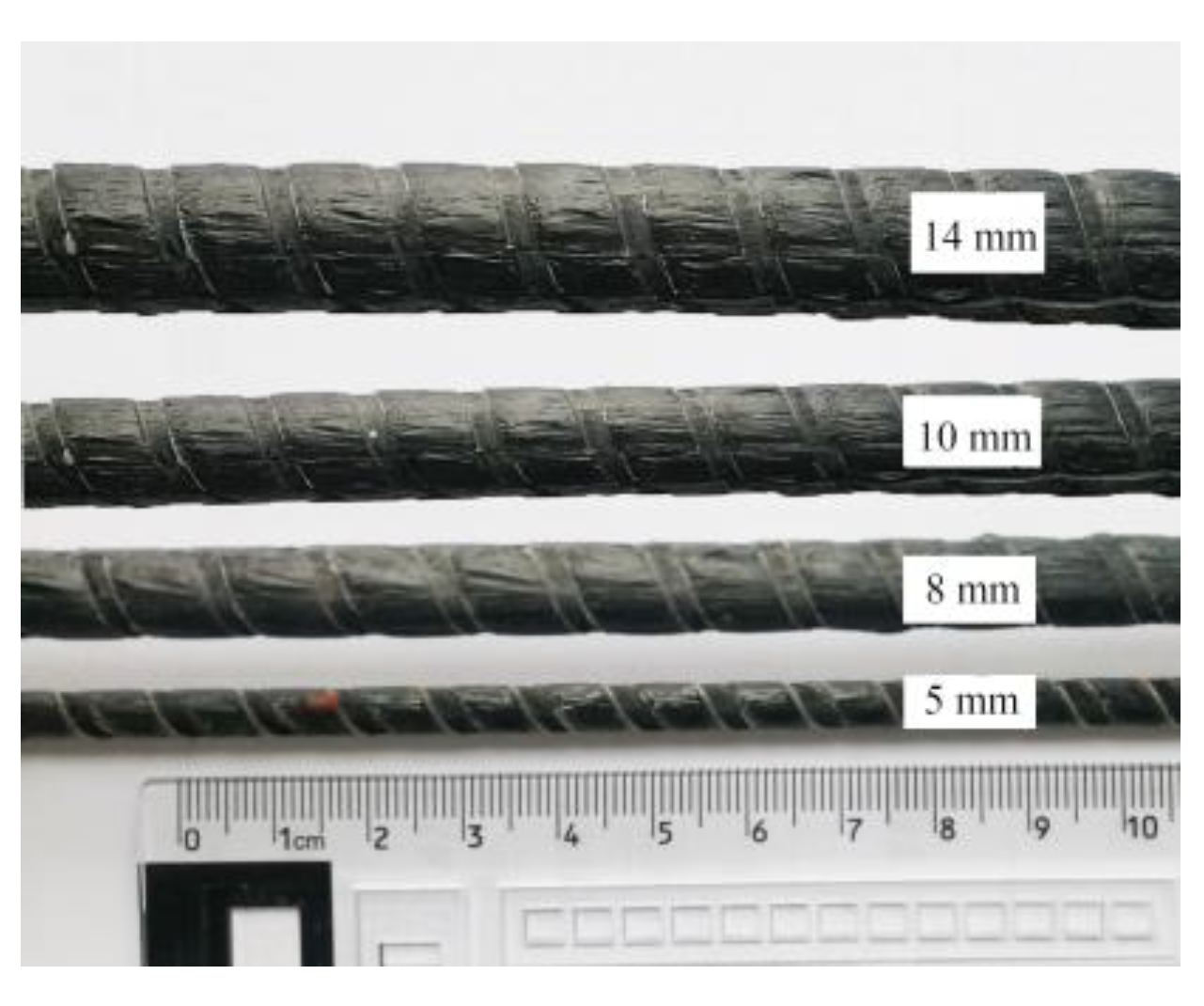
2.1. Materials

The steel pipe material examined was No. 45 steel based on GB/T 699-2015, and its mechanical properties are shown in Table 1. The embossed CFRP tendons were used to obtain superior anchorage performance due to the significant friction and mechanical engagement with the bonding medium [32]. The mechanical properties of CFRP tendons provided by the manufacturer are typical values, as shown in Table 2. The hardness and mechanical properties of epoxy resin are similar to those of the CFRP tendon and resin matrix, respectively [33]. Therefore, epoxy resin, which exhibited superior anchoring performance, was used for CFRP tendon anchoring in the tests. According to the manufacturer, the elastic modulus, the average bond strength, and the compressive strength of the used epoxy resin are 2.6 GPa, 20.9 MPa, and 106.6 MPa, respectively. Both the curing temperature and working temperature of epoxy resin are room temperature, and epoxy resin was cured for three days.

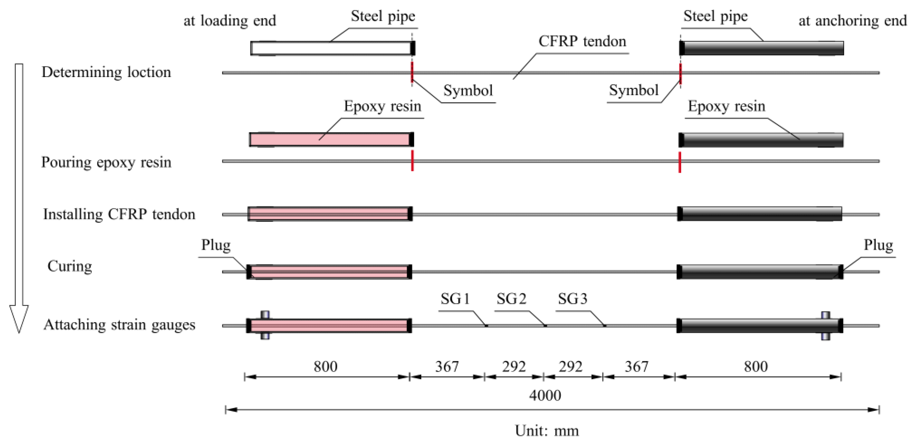
2.2. Specimens and Preparation

A total of 48 bond-type anchorage specimens with different diameters of CFRP tendons were prepared. The bond-type anchorage composed of steel pipe, CFRP tendon, and epoxy resin was used, as shown in Figure 1. The nominal diameters of CFRP tendons were 5, 8, 10, and 14 mm, as shown in Figure 2. In the preparation process of specimens, the anchoring position corresponding to the steel pipe and the tendon was firstly determined and marked. After the tendon was positioned, one end of the steel pipe was sealed, and the other end was poured with epoxy resin. The steel pipe oscillated continuously during pouring to ensure the bonding and tightness between the CFRP tendon and epoxy resin. Then the tendon was inserted from one end and stopped at the mark. The plug at the other end was sealed when the CFRP tendon was installed at the marked position. Finally, the strain gauges were attached at the designated position (relative to the external radius of the tendon). Figure 3 shows more details of strain gauges. Figure 4 shows the flow chart of the whole preparation process.

2.3. Test Setup and Procedure

The specimens were used in the static load tests conducted on the concrete device, as shown in Figure 5. The concrete loading device was divided into the outer protective frame and curved saddle, and its material was C40 concrete reinforcement. The curved saddle was placed in the middle of the outer protective frame. There were three saddles with bending radii of 3, 8, and 12 m. In addition, a set of unbent specimens were set up for comparison. The parameters of the saddles were selected based on a practical suspension bridge. Three slotted holes were opened on both sides of the outer protective frame for CFRP tendon anchoring channels. The corners of the three saddles were chamfered to prevent the CFRP tendon from being affected by local stress concentrations during loading.
The test used one hollow jack with a range of 600 kN, a maximum tension stroke of 150 mm, and one spoke load sensor with a measuring range of 1600 kN. Before the tensile tests, a preloading process with 5% of the ultimate tensile force was conducted. The loading speed was based on JC/T 2404-2017 [34], and each level was loading for 30 s. The fracture force, slippage of CFRP tendons, and strain in the free lengths of CFRP tendons were measured. Meanwhile, different failure modes of specimens were observed.

3. Results and Discussions

3.1. General

Loading applied to all specimens was continuous until specimens failed. These specimens showed no apparent changes at the early loading stage. With the increase in load, the intermittent sound of fibers was heard. Then, the specimens failed with a thud sound, and the anchorage and jack were ejected from the test device together. In order to analyze the causes of the failure modes of the specimens, the typical failure figure of the specimens was compared with the finite elements and shown in the finite element part. An efficiency coefficient η was introduced to evaluate the tensile properties of CFRP tendons in the bending state. The efficiency coefficient [Equation (1)] was used to evaluate the reduction effect of bending on the ultimate tensile force of the CFRP tendon, where F is average fracture force and F c u is ultimate tensile force. Table 3 lists the results for each group of specimens in the static load tests.
η = F F c u

3.2. Fracture Force of the Specimens

Figure 6 shows the average fracture force histogram of these specimens. As seen in the figures, when compared with the unbent specimens R0, the fracture force of the specimens with the bending radius of 3 m decreased by 23.91%, 38.05%, 32.26%, and 18.94%, respectively. In addition, the fracture force of CFRP tendons with the same diameter increased as the bending radius increased. The test results suggest that the fracture force of CFRP tendons was significantly reduced due to bending. In addition, the fracture force of R3D5 (35 kN) exceeded that of R8D5 (33 kN) and R12D5 (36 kN). The abnormal data can be interpreted as follows: the failure position was related to material defect, loading position, stress concentrations, and steel pipe port effect; the ultimate tensile force of the CFRP tendon with a diameter of 5 mm was low, and it had large discreteness.

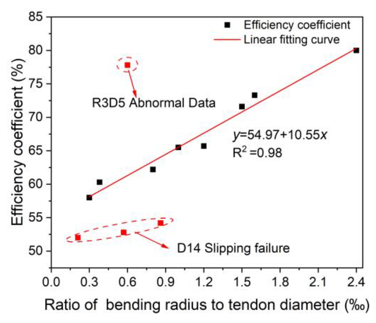
3.3. The Ratio of the Bending Radius to the Tendon Diameter

Figure 7 shows the relationship between the efficiency coefficient and the ratio of the bending radius to the tendon diameter. It can be seen that the efficiency coefficient is linearly related to the ratio of bending radius to the tendon diameter, except the slipping failure of the specimens with a 14 mm CFRP tendon. Moreover, combined with the failure modes of the specimens, it was observed that the ratio of the bending radius to the tendon diameter was below 2.4, the efficiency coefficient was less than 80%, and the failure modes of the specimens were mostly shear failure. Therefore, it is suggested that the ratio of the bending radius to the tendon diameter should be more than 2.4 in engineering practice.

4. Numerical Simulation

4.1. General

A finite element (FE) model was established using ANSYS version 18.2 mechanical software to validate the test results and extend the research. Figure 8 presents the outline of the simulation model. The critical dimensions and parameters were determined from the experimental tests. The failure criterion for CFRP tendons uses the Tsai–Wu failure criterion. According to the structural and mechanical characteristics of the test device, the contact interface between the CFRP tendon and saddle should be addressed in numerical simulation. Three features of the interface can be applied: (1) impenetrability constraints are set between surfaces; (2) the contact interface can transmit normal pressure and tangential friction; (3) normal tension can hardly be transmitted. The stress distributions and the effects of the contact interface on the mechanical properties of CFRP tendons were studied by FE analysis.

4.2. Materials

Two parts of the FE model were specified as having different materials, and the CFRP tendon was assigned with given values for each material parameter based on Table 2. The axial and radial mechanical properties of the CFRP tendon are different. Therefore, the anisotropic elastic material model was chosen, and the primary fiber direction was defined as material orientation X. In addition, CFRP material is different from a traditional steel material, because it is an anisotropic material; therefore, the maximum stress and maximum strain criteria applied to traditional material are no longer applicable. At present, the Tsai–Wu criterion is often used for the simulation of composite materials. The Tsai–Wu criterion can reflect the interconnection between the damage strength X, Y, and Z, and can more realistically reflect the damage pattern of composite materials [35,36].

4.3. Elements

Advanced three-dimensional element SOLID185 was adopted to simulate the CFRP tendon and concrete saddle based on previous studies [37]. The CFRP tendon was discretized with axial and radial mesh sizes of 4 mm and around 1 mm, respectively, as shown in Figure 8. A mesh sensitivity analysis was conducted before selecting the mesh sizes. The interface (between CFRP tendon and saddle) in Figure 8 was simulated in ANSYS as contact elements. Surface-to-surface contact pairs (CONTA 174 and TARGE 170) simulated the interactions. The contact parameters were normal contact stiffness factor (FKN = 0.1) and initial closure factor (ICONT = 0.1) [32]. The friction coefficient (FC) between the CFRP tendon and concrete saddle was 0.2 based on the test results [38], preferably reflecting the real contact state. Default settings set the other contact parameters. The contact nonlinearity was calculated by an augmented Lagrangian contact algorithm. Therefore, it is accurate to simulate the variable radial compression stress and tangential friction force between the contact interface.

4.4. Boundary Conditions and Loading

The boundary conditions and loading positions are displayed in Figure 8. On the bottom of the concrete saddle, all rotations and displacements (UX = UY = UZ = 0, ROTX = ROTY = ROTZ = 0) were constrained. The displacement of the CFRP tendon cross-section nodes at the anchoring end was constrained based on the actual constraint of the anchorage. A uniform load was applied over the cross-section of the other end of the CFRP tendon.

4.5. Model Validation

The efficiency coefficient of the FE models was compared with the corresponding test results to validate the reliability of the FE models. Table 4 lists the results for each group of specimens in the static load tests and FE analysis. The results suggest that the simulated values of the efficiency coefficient for four bending radii agreed well with the corresponding test results; in addition to the abnormal data, the maximum value of deviation (δ) was less than 6.0%. Therefore, it can be concluded that the established FE models are reliable.

4.6. Load–Strain Curves of CFRP Tendons

Figure 9 shows the load–strain curves of typical specimens investigated experimentally and numerically, drawn only before the fracture load. CFRP tendons with a diameter of 8, 10, and 14 m were selected as the research objects, and the rest of the specimens had the same trend of change. CFRP tendons did not reach their total capacity due to bending. From the strain values, the loading end had the maximum deformability. At the same time, most load–strain curves showed linear behavior. The same trend was also observed from the numerical simulation results, and the values were very close. The strain dispersion for the CFRP tendons was not significant during the lower loading stage (before 20% F c u ), and it increased with the load after that. As the load increased, significant nonlinear segments appeared at the end part of the load–strain curves of some specimens. This is because as the load increased, cracks appeared on the surface of the CFRP tendon, which may lead to the deviation in the strain gauge direction from the longitudinal direction of the tendon. Han et al. [30] pointed out that this kind of nonlinear segment was the typical characteristic of the splitting failure for the unidirectional-fiber-reinforced composites. In addition, a spiral curve appeared at the lower loading stage of specimen R8D8 due to the long continuous loading time in the experiment; thus, it may lead to anchorage loosening or jack oil leakage in a short time. For specimen R12D10, SG1 changed significantly when the load exceeded 90 kN. This is because many cracks appeared, and the screwed wires lost their mutual constraint, leading the CFRP tendon to burst into multiple strands.

4.7. Failure Mode

Determining the failure modes of the specimens was one of the most critical outcomes in the research, and offered more understanding of load transfer. Figure 10 shows the comparative analysis of the finite element and test failure modes of the specimens. It can be seen from the figure that the failure mode is related to the stress distribution of the CFRP tendons. For the R3 saddle, specimens R3D5 and R3D8 presented an uneven fracture section, while for the R8 saddle, specimens R8D8 and R8D10 presented typical shear failure. The results show that a larger bending radius led to a more uniform stress distribution on the CFRP tendon cross-section, thus resulting in synchronous fracture of the fibers. For the R12 saddle, specimen R12D8 presented shear fractures, while multiple parallel longitudinal cracks were observed on the surface of R12D10 and R12D14, with lengths ranging from 2 to 7 cm. From the stress distribution of the CFRP tendons after failure of the finite element model, it can be seen that the surface stress distribution of the CFRP tendons where splitting damage occurs is more uniform, and the larger the diameter of the CFRP tendons, the more likely it is that splitting damage occurs. In addition, for the specimens of the 14 mm CFRP tendon, the CFRP tendons finally had varying degrees of slip. This is attributed to the fact that the CFRP tendon with a larger diameter causingmore epoxy resin out of the steel pipe during the installation, resulting in insufficient adhesion between the CFRP tendon and residual bonding medium. Based on the above analysis, it can be seen that increasing the bending radius contributed to the uniformity of the stress distribution. Additionally, increasing the diameter of the CFRP tendon made it brittle and difficult to anchor, so the splitting failure and slipping failure were observed.

4.8. Parameter Evaluation

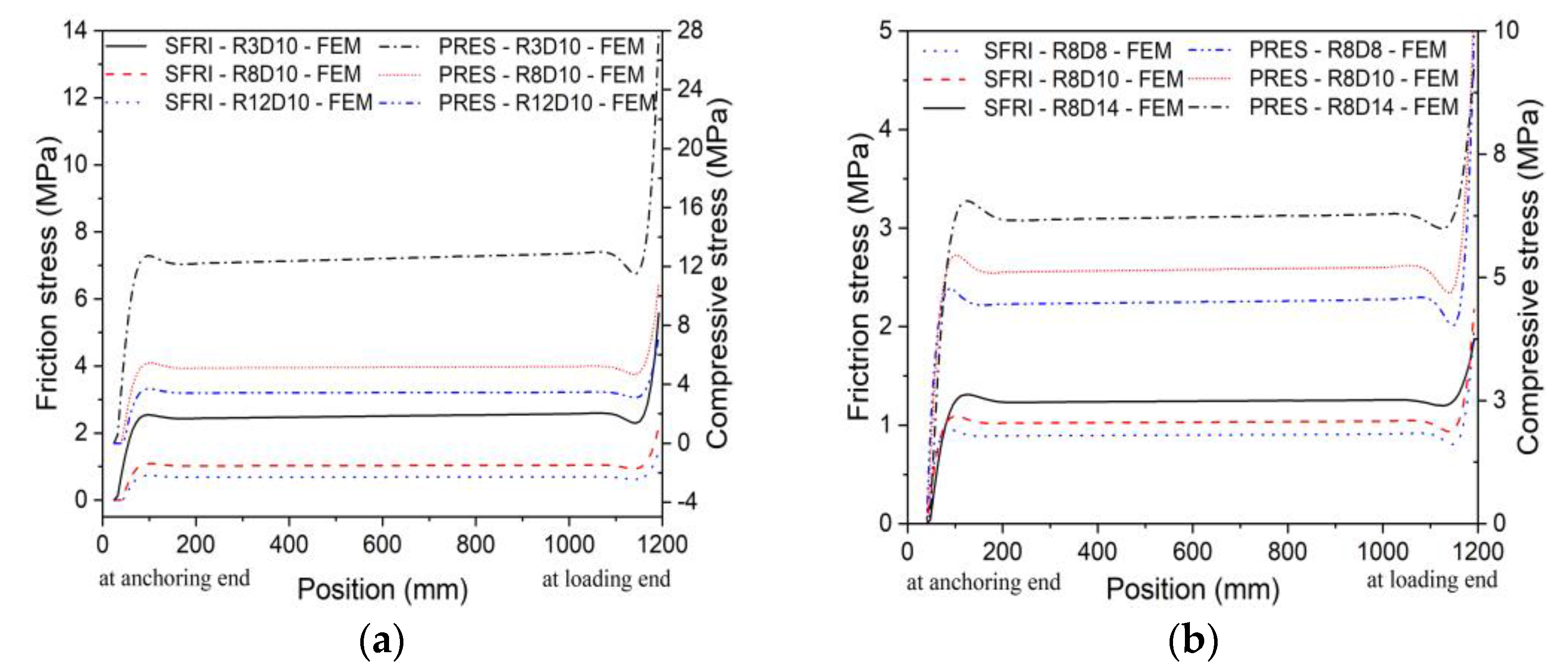
4.8.1. Effect of CFRP Tendon Diameter and Bending Radius on Stress Distribution

The stress distributions of CFRP tendons were analyzed using the FE models, as shown in Figure 11. The von Mises cloud diagrams show that the stress was maximized at the anchoring end (R3) and loading end (R8 and R12). With increasing bending radius, the stress gradient along the length of the CFRP tendon decreased, and the stress distribution was more uniform. An increase in diameter led to a reduction in peak stress, indicating that CFRP tendons with a smaller diameter were more likely to provide the advantages of CFRP composites.
Figure 12 shows the friction stress and contact compressive stress distribution of CFRP tendons by numerical simulation, where SFRI is friction stress and PRES is compressive stress. The friction and contact compressive stress distributions of CFRP tendons were uniform except at the loading end. Although the load-bearing capacity of CFRP tendons decreased with the decrease in bending radius, the friction stress and compressive stress increased significantly, as shown in Figure 12a. The results show that reducing the bending radius had significant adverse effects on the properties of CFRP tendons. The friction stress and contact compressive stress increased with the increase in CFRP tendon diameter, as shown in Figure 12b. However, the effect of friction stress caused by increasing CFRP tendon diameter on the properties of CFRP tendons is unclear. This is because the load-bearing capacity of CFRP tendons increased accordingly, increasing the contact compressive stress.

4.8.2. Effect of Bending Radius of the Saddle on Efficiency Coefficient

Figure 13 compares the efficiency coefficient of CFRP tendons simulated by FE analysis with the test results. In addition to the abnormal data, the efficiency coefficient increased nonlinearly with increasing bending radius. When the bending radius increased from 3 to 12 m, the efficiency coefficient of D8 increased from 62.93% to 72.41%, an increase of close to 10%. However, when the bending radius increased from 3 to 12 m, the efficiency coefficient of D14 increased by only 5.96%. The results show that increasing the bending radius was more conducive to improving the performance of CFRP tendons with a smaller diameter.
Figure 14 shows the effect of saddle bending radius on the axial stress and shear stress distributions of CFRP tendons in FE analysis. The axial stress of R3D8 reached a minimum because the CFRP tendon was subjected to significant shear stress, which caused the ultimate tensile force to be significantly reduced. In addition, as the bending radius decreased, the shear stress increased sharply. It can be observed that CFRP tendons with a smaller bending radius presented higher shear stress concentrations at both ends.
The test and FE results show that decreasing bending radius increased the force perpendicular to the fiber direction, which had a significant adverse effect on the properties of CFRP tendons. This is because the shear strength of CFRP tendons is only 7% of the tensile strength. Combined with the failure modes in the test, CFRP tendons were extruded by epoxy resin in the steel pipe. When the CFRP tendon extended out of the steel pipe, the radial extrusion constraint suddenly disappeared, resulting in transverse expansion of CFRP wires. Interface failure caused the CFRP tendon to lose load-bearing capacity due to shear stress, and the tensile fracture of the fibers led to the final fracture. In engineering practice, it is suggested that bending radius of CFRP tendons should be more than or equal to 8 m, and the shear force concentrations should be concerned.

4.8.3. Effect of Diameter of the CFRP Tendon on Efficiency Coefficient

Figure 15 compares the efficiency coefficient of CFRP tendons with different diameters simulated by FE analysis with the test results. In addition to the abnormal data, as the diameter of CFRP tendons increased, the efficiency coefficient of all specimens decreased significantly. When the diameter of CFRP tendons reached 14 mm, the corresponding efficiency coefficients of R3 and R12 were 50.56% and 56.50%, respectively, which were very low. The results show that increasing the diameter of CFRP tendons had a significant adverse effect on performance.
Figure 16 shows the effect of diameter on the axial stress and shear stress distributions of CFRP tendons in FE analysis. As the diameter decreased, the axial stress increased significantly, indicating that CFRP tendons with a smaller diameter were more likely to provide the advantages of CFRP composites. The trend of the three curves in Figure 16a was consistent due to the uniform distribution of axial stress. Although the change in diameter had little effect on the shear stress, CFRP tendons still presented shear stress concentrations at both ends.
The test and FE results show that CFRP tendons with a smaller diameter had superior properties. Combined with the previous conclusion, CFRP tendons with a larger diameter had worse flexibility, thus resulting in fracture by tension and local shear stress concentrations. Therefore, CFRP tendons with a diameter smaller than or equal to 8 mm are preferred in main cables for holding a high efficiency coefficient.

4.8.4. Effect of Friction Coefficient (FC) on Efficiency Coefficient

Considering the limitation of the experiment, the effect of contact friction between the CFRP tendon and saddle on the properties of CFRP tendons was studied by changing the friction coefficient (FC) in FE analysis. The efficiency coefficient–friction coefficient relationship of CFRP tendons is shown in Figure 17. When increasing the friction coefficient, the efficiency coefficient decreased significantly, revealing the adverse effect of friction on the properties of CFRP tendons. As the friction coefficient increased from 0.1 to 0.5, the corresponding efficiency coefficient of D14 decreased from 59.84% to 25.04%, a decrease of 34.8%. Therefore, increasing the friction coefficient, especially for the CFRP tendon with a larger diameter, degraded its mechanical properties under combined loads.
Figure 18 shows the effect of friction on the axial stress and shear stress distributions of CFRP tendons in FE analysis. The change in friction coefficient had little effect on the shear stress but significantly affected the axial stress. As the friction coefficient increased, the load-bearing capacity of CFRP tendons was significantly reduced; thus, the axial stress with the friction coefficient of 0.5 reached a minimum. The results suggest that CFRP tendons with a smaller friction coefficient had superior properties. Therefore, it is suggested that some low friction materials should be coated between the CFRP tendon and saddle contact surface to reduce the friction coefficient.

5. Conclusions

In this research, a series of static load tests were carried out to study the mechanical properties of CFRP tendons subjected to combined tension and bending, and the research was extended through FE simulations. Based on the results, the conclusions are summarized as follows:
1.
The fracture force and deformability of the specimens were observed to be significantly decreased with the decrease in the bending radius. Meanwhile, the CFRP tendon diameter also was found to have major influencing effects on the ultimate capacity of the specimens.
2.
The efficiency coefficients (the ratio of the fracture force to the ultimate force) were found to be significantly affected by the increases in the bending radius. In the test, the efficiency coefficients of D8, D10, and D14 increased by 11.21%, 7.74%, and 2.26%, respectively, when the bending radius was increased from 3 to 12 m. Meanwhile, the efficiency coefficient of D14 increased by only 2.26%. Therefore, increasing the bending radius was more conducive to improving the performance of CFRP tendons with a smaller diameter.
3.
The failure modes were found to be influenced by the bending radius and the CFRP tendon diameter. The test results show that increasing the bending radius contributed to the uniformity of the stress distribution. The interface failure caused the CFRP tendon to lose load-bearing capacity due to shear stress, and the tensile fracture of the fibers led to the final fracture. Additionally, increasing the diameter of the CFRP tendon made it brittle and difficult to anchor, so the splitting failure and slipping failure were observed. The ratio of the bending radius to the tendon diameter was below 2.4, the efficiency coefficient was less than 80%, and the failure modes of the specimens were mostly shear failure.
4.
Combined with the FE model analysis, it was shown that the CFRP tendons with a smaller bending radius presented higher shear stress concentrations at both ends and had a significant adverse effect on the contact friction stress. The change in friction coefficient had little effect on the shear stress but had a significant effect on the axial stress of CFRP tendons. As the friction coefficient increased, the load-bearing capacity of CFRP tendons was significantly reduced, and the axial stress with the friction coefficient of 0.5 reached a minimum. In addition, the results of the FE models agreed well with the test results, and provided a reliable basis for CFRP composites used in practical engineering.

Author Contributions

Conceptualization, L.J.; methodology L.J.; formal analysis, W.Z.; investigation, W.Z.; writing—original draft preparation, W.Z.; writing—review and editing, J.X.; supervision, Y.J.; project administration, Y.J.; Data curation, J.X.; Visualization, J.X. All authors have read and agreed to the published version of the manuscript.

Funding

This work was supported by the National Natural Science Foundation of China (51878488).

Data Availability Statement

Some or all data, models, or code that support the findings of this study are available from the corresponding author upon reasonable request (load-strain data and FE data).

Acknowledgments

The authors are greatly indebted to the anonymous reviewers for their valuable comments and suggestions, which greatly helped in improving the overall quality of this manuscript.

Conflicts of Interest

The authors declare no conflict of interest.

References

  1. Rohleder, W.J., Jr.; Tang, B.; Doe, T.A.; Grace, N.F.; Burgess, C.J. Carbon Fiber-Reinforced Polymer Strand Application on Cable-Stayed Bridge, Penobscot Narrows, Maine. Transp. Res. Rec. 2008, 2050, 169–176. [Google Scholar] [CrossRef]
  2. Xiong, W.; Cai, C.S.; Zhang, Y.; Xiao, R. Study of super long span cable-stayed bridges with CFRP components. Eng. Struct. 2011, 33, 330–343. [Google Scholar] [CrossRef]
  3. Yang, Y.Q.; Fahmy, M.F.M.; Guan, S.J.; Pan, Z.H.; Zhan, Y.; Zhao, T.D. Properties and applications of FRP cable on long-span cable-supported bridges: A review. Compos. Part B-Eng. 2020, 190, 107934. [Google Scholar] [CrossRef]
  4. Jiang, Y.; Jia, L. Study on Applicable Spans and Static Performance of the Suspension Bridges using CFRP Cables. In Proceedings of the Advances in Civil Engineering, PTS 1-6, Uttar Pradesh, India, 14–16 October 2011; pp. 1115–1119. [Google Scholar]
  5. Jiang, Y.; Jia, L. Contrastive Analysis on Limitation Span between Suspension Bridge using steel and CFRP Cable. In Proceedings of the Advanced Research on Civil Engineering and Material Engineering, Wuhan, China, 25–26 August 2012; pp. 57–60. [Google Scholar]
  6. Meiarashi, S.; Nishizaki, I.; Kishima, T.I. Life-cycle cost of all-composite suspension bridge. J. Compos. Constr. 2002, 6, 206–214. [Google Scholar] [CrossRef]
  7. Liu, Y.; Zwingmann, B.; Schlaich, M. Carbon Fiber Reinforced Polymer for Cable Structures-A Review. Polym.-Basel 2015, 7, 2078–2099. [Google Scholar] [CrossRef] [Green Version]
  8. Xian, G.; Guo, R.; Li, C.; Wang, Y. Mechanical performance evolution and life prediction of prestressed CFRP plate exposed to hygrothermal and freeze-thaw environments. Compos. Struct. 2022, 293, 115719. [Google Scholar] [CrossRef]
  9. Lal, H.M.; Uthaman, A.; Li, C.; Xian, G.; Thomas, S. Combined effects of cyclic/sustained bending loading and water immersion on the interface shear strength of carbon/glass fiber reinforced polymer hybrid rods for bridge cable. Constr. Build. Mater. 2022, 314, 125587. [Google Scholar] [CrossRef]
  10. Wang, X.; Wu, Z. Integrated high-performance thousand-metre scale cable-stayed bridge with hybrid FRP cables. Compos. Part B-Eng. 2010, 41, 166–175. [Google Scholar] [CrossRef]
  11. Feng, B.; Wang, X.; Wu, Z.S. Static and Fatigue Behavior of Multitendon CFRP Cables with Integrated Anchorages. J. Compos. Constr. 2019, 23, 4019051. [Google Scholar] [CrossRef]
  12. Al-Mayah, A.; Soudki, K.; Plumtree, A. Mechanical behavior of CFRP rod anchors under tensile loading. J. Compos. Constr. 2001, 5, 128–135. [Google Scholar] [CrossRef]
  13. Sudarisman; Davies, I.J. The effect of processing parameters on the flexural properties of unidirectional carbon fibre-reinforced polymer (CFRP) composites. Mater. Sci. Eng. A-Struct. Mater. Prop. Microstruct. Process. 2008, 498, 65–68. [Google Scholar] [CrossRef]
  14. Rozylo, P.; Falkowicz, K.; Wysmulski, P.; Debski, H.; Pasnik, J.; Kral, J. Experimental-Numerical Failure Analysis of Thin-Walled Composite Columns Using Advanced Damage Models. Materials 2021, 14, 1506. [Google Scholar] [CrossRef] [PubMed]
  15. Debski, H.; Samborski, S.; Rozylo, P.; Wysmulski, P. Stability and Load-Carrying Capacity of Thin-Walled FRP Composite Z-Profiles under Eccentric Compression. Materials 2020, 13, 2956. [Google Scholar] [CrossRef]
  16. Kadhim, M.M.A.; Jawdhari, A.; Nadir, W.; Cunningham, L.S. Behaviour of RC beams strengthened in flexure with hybrid CFRP-reinforced UHPC overlays. Eng. Struct. 2022, 262, 114356. [Google Scholar] [CrossRef]
  17. Peng, K.-D.; Huang, B.-T.; Xu, L.-Y.; Hu, R.-L.; Dai, J.-G. Flexural strengthening of reinforced concrete beams using geopolymer-bonded small-diameter CFRP bars. Eng. Struct. 2022, 256, 113992. [Google Scholar] [CrossRef]
  18. Vo-Le, D.; Tran, D.T.; Pham, T.M.; Ho-Huu, C.; Nguyen-Minh, L. Re-evaluation of shear contribution of CFRP and GFRP sheets in concrete beams post-tensioned with unbonded tendons. Eng. Struct. 2022, 259, 114173. [Google Scholar] [CrossRef]
  19. de Menezes, E.A.W.; da Silva, L.V.; Cimini, C.A.; Luz, F.F.; Amico, S.C. Numerical and Experimental Analysis of the Tensile and Bending Behaviour of CFRP Cables. Polym. Polym. Compos. 2017, 25, 643–649. [Google Scholar] [CrossRef]
  20. Luz, F.F.; Menezes, E.A.W.; Silva, L.V.; Cimini, C.A., Jr.; Marczak, R.J.; Amico, S.C. Bending behavior of CFRP cables in the nonlinear displacement range. J. Braz. Soc. Mech. Sci. Eng. 2019, 42, 1–7. [Google Scholar] [CrossRef]
  21. Han, Q.; Wang, L.; Xu, J. Experimental research on mechanical properties of transverse enhanced and high-temperature-resistant CFRP tendons for prestressed structure. Constr. Build. Mater. 2015, 98, 864–874. [Google Scholar] [CrossRef]
  22. Arczewska, P.; Polak, M.A.; Penlidis, A. Relation between Tensile Strength and Modulus of Rupture for GFRP Reinforcing Bars. J. Mater. Civ. Eng. 2019, 31, 4018362. [Google Scholar] [CrossRef]
  23. Fang, Y.W.; Fang, Z.; Jiang, Z.W.; Jiang, R.N.A.; Zhou, X.H. Investigation on failure behavior of carbon fiber reinforced polymer wire subjected to combined tension and bending. Compos. Struct. 2021, 267, 113927. [Google Scholar] [CrossRef]
  24. Cai, D.A.; Wang, X.P.; Shi, Y.H.; Hao, X.F.; Qian, Y.; Zhou, G.M. A New Interfacial Model for Transverse Mechanical Properties of Unidirectional Fiber Reinforced Composites. Fibers Polym. 2021, 22, 430–441. [Google Scholar] [CrossRef]
  25. Hwash, M.; Knippers, J. Load-Bearing Capacity of Deviated CFRP Strips. J. Compos. Constr. 2014, 18, 4013055. [Google Scholar] [CrossRef]
  26. Suwei, H.O.U.; Ping, Z.; Shizhong, Q.; Cuijuan, L.I. Experimental Investigation of Friction Properties between CFRP Main Cable and Saddle of Suspension Bridge. J. Southwest Jiaotong Univ. 2011, 46, 391–397. [Google Scholar]
  27. Fan, H.F.; Vassilopoulos, A.P.; Keller, T. Experimental and numerical investigation of tensile behavior of non-laminated CFRP straps. Compos. Part B-Eng. 2016, 91, 327–336. [Google Scholar] [CrossRef]
  28. Liu, M.H.; Qiang, S.Z.; Xu, G.P.; Ren, W.P. Study and Prototype Design of a Suspension Bridge with Ultra-Long Span and CFRP Main Cables. J. Highw. Transp. Res. Dev. 2014, 8, 47–56. [Google Scholar]
  29. Wang, X.; Wang, Z.H.; Wu, Z.S.; Cheng, F. Shear behavior of basalt fiber reinforced polymer (FRP) and hybrid FRP rods as shear resistance members. Constr. Build. Mater. 2014, 73, 781–789. [Google Scholar] [CrossRef]
  30. Han, Q.H.; Wang, L.C.; Xu, J. Experimental research on fracture behaviors of damaged CFRP tendons: Fracture mode and failure analysis. Constr. Build. Mater. 2016, 112, 1013–1024. [Google Scholar] [CrossRef]
  31. Xiang, Y.; Fang, Z.; Wang, C.L.; Zhang, Y.; Fang, Y.W. Experimental Investigations on Impact Behavior of CFRP Cables under Pretension. J. Compos. Constr. 2017, 21, 4016087. [Google Scholar] [CrossRef]
  32. Rizkalla, S.H.; Busel, J.P. Prestressing Concrete Structures with FRP Tendons (ACI 440.4R-04). In Proceedings of the Structures Congress 2005, New York, NY, USA, 20–24 April 2005. [Google Scholar]
  33. Fang, Z.; Zhang, K.; Tu, B. Experimental investigation of a bond-type anchorage system for multiple FRP tendons. Eng. Struct. 2013, 57, 364–373. [Google Scholar] [CrossRef]
  34. JC/T 2404-2017; Chinese Standards. Test Method for Tensile Behavior of Continuous Fiber-Reinforced Ceramic Composites at Room Temperature. China Standards Press: Beijing, China, 2017.
  35. Tsai, S.W.; Wu, E.M. A General Theory of Strength for Anisotropic Materials. J. Compos. Mater. 1971, 5, 58–80. [Google Scholar] [CrossRef]
  36. Hashin, Z. Failure criteria for unidirectional fiber composites. J. Appl. Mech.-Trans. Asme 1980, 47, 329–334. [Google Scholar] [CrossRef]
  37. Cai, D.S.; Xu, Z.H.; Yin, J.; Liu, R.G.; Liang, G. A numerical investigation on the performance of composite anchors for CFRP tendons. Constr. Build. Mater. 2016, 112, 848–855. [Google Scholar] [CrossRef]
  38. Yu, T.L.; Zhang, L.Y. Friction Loss of Externally Prestressed Concrete Beams with Carbon Fiber-Reinforced Polymer Tendons. In Proceedings of the Advances in Structures, PTS 1-5, Hamburg, Germany, 28–30 March 2011; pp. 3701–3706. [Google Scholar]
Figure 1. Bond-type anchorage (mm).
Buildings 13 00988 g001
Figure 2. CFRP tendon (mm).
Buildings 13 00988 g002
Figure 3. Details of strain gauges.
Buildings 13 00988 g003
Figure 4. The preparation process of specimens (mm).
Buildings 13 00988 g004
Figure 5. Test loading device: (a) schematic; (b) photograph (mm).
Buildings 13 00988 g005
Figure 6. Average fracture force histogram of specimens.
Buildings 13 00988 g006
Figure 7. Relationship between the efficiency coefficient and the ratio of the bending radius to the tendon diameter.
Buildings 13 00988 g007
Figure 8. FE model of CFRP tendon and concrete saddle.
Buildings 13 00988 g008
Figure 9. Load–strain curves of CFRP tendons: (a) R3D10; (b) R8D8; (c) R12D8; (d) R12D10.
Buildings 13 00988 g009
Figure 10. Failure mode of typical specimens: (a) R3D5; (b) R3D8; (c) R8D8; (d) R8D10; (e) R12D8; (f) R12D10; (g) R3D14; (h) R12D14.
Buildings 13 00988 g010
Figure 11. Stress distribution of CFRP tendons: (a) R3; (b) R8; (c) R12.
Buildings 13 00988 g011
Figure 12. Friction stress and contact compressive stress distributions of CFRP tendons: (a) D10; (b) R8.
Buildings 13 00988 g012
Figure 13. Curves of bending radius and efficiency coefficient.
Buildings 13 00988 g013
Figure 14. Effect of bending radius on the stress distributions of CFRP tendons: (a) axial stress; (b) shear stress.
Buildings 13 00988 g014
Figure 15. Curves of diameter and efficiency coefficient.
Buildings 13 00988 g015
Figure 16. Effect of diameter on the stress distributions of CFRP tendons: (a) axial stress; (b) shear stress.
Buildings 13 00988 g016
Figure 17. Curves of friction coefficient and efficiency coefficient.
Buildings 13 00988 g017
Figure 18. Effect of friction coefficient on the stress distribution of CFRP tendons: (a) axial stress; (b) shear stress.
Buildings 13 00988 g018
Table 1. Mechanical properties of steel pipe.
MaterialElastic Modulus (GPa)Tensile Strength (MPa)Yield Strength (MPa)Elongation (%)
No.45 steel21060035516
Table 2. Material properties of CFRP tendon.
X τ   ( MPa ) X C   ( MPa ) Y τ   ( MPa ) Y C   ( MPa ) S L   ( MPa ) S τ   ( MPa ) E X   ( GPa ) E y   ( GPa ) G X y   ( GPa ) G X Z   ( GPa ) G y Z   ( GPa ) v X Y v Y Z
2300144057228711215010.56.26.27.10.270.02
Note: The fiber longitudinal direction was defined as material orientation X, and the other two directions perpendicular to the fiber direction were defined as material orientations Y and Z; X τ  = tensile strength along the fiber direction;  X C  = compressive strength along the fiber direction;  Y τ  = tensile strength perpendicular to the fiber direction;  Y C  = compressive strength perpendicular to the fiber direction;  S L  = shear strength along the fiber direction;  S τ  = shear strength perpendicular to the fiber direction;  E X  = elastic modulus along the fiber direction;  E y  = elastic modulus perpendicular to the fiber direction;  G X y G X Z G y Z  = shear modulus; and  v X Y = v X Z v Y Z  = Poisson’s ratio.
Table 3. Results of testing.
R (m)D (mm)Group F 1   ( kN ) F c u   ( kN ) η 1   ( % )
35R3D535.1245.1677.78
8R3D869.76115.6160.34
10R3D10104.79180.6458.01
14R3D14184.03354.0651.98
85R8D533.1245.1673.33
8R8D875.74115.6165.52
10R8D10111.78180.6461.88
14R8D14187.03354.0652.82
125R12D536.1345.1680.00
8R12D882.72115.6171.55
10R12D10118.76180.6465.75
14R12D14192.03354.0654.24
05R0D546.1645.16102.22
8R0D8112.62115.6197.41
10R0D10154.69180.6485.64
14R0D14227.04354.0664.12
Note: R = bending radius of saddle; D = diameter of CFRP tendon; F 1  = average fracture force of CFRP tendon by testing;  F c u  = ultimate tensile force of CFRP tendon;  η 1  = efficiency coefficient by testing =  F 1 / F c u .
Table 4. Results of FE models.
R (m)D (mm)Group F 2   ( kN ) η 2   ( % ) δ   ( % )
35R3D532.1171.118.57
8R3D872.7562.934.29
10R3D10103.7957.460.95
14R3D14179.0350.562.72
85R8D534.1275.563.03
8R8D877.7467.242.63
10R8D10114.7763.542.68
14R8D14190.0353.671.60
125R12D537.1382.222.78
8R12D883.7272.411.20
10R12D10120.7666.851.68
14R12D14200.0356.504.17
05R0D544.1697.784.35
8R0D8114.6199.141.77
10R0D10158.6887.852.58
14R0D14240.0467.805.73
Note: F 2  = average fracture force of CFRP tendon by FE analysis;  η 1  = efficiency coefficient by test =  F 1 / F c u   η 2    = efficiency coefficient by FE analysis =  F 1 / F c u   ; and  δ  = deviation =  | ( η 2 η 1 ) /   η 1 | .
Disclaimer/Publisher’s Note: The statements, opinions and data contained in all publications are solely those of the individual author(s) and contributor(s) and not of MDPI and/or the editor(s). MDPI and/or the editor(s) disclaim responsibility for any injury to people or property resulting from any ideas, methods, instructions or products referred to in the content.

