
Experimental and Numerical Investigation of Hot Extruded Inconel 718
 , and
, and 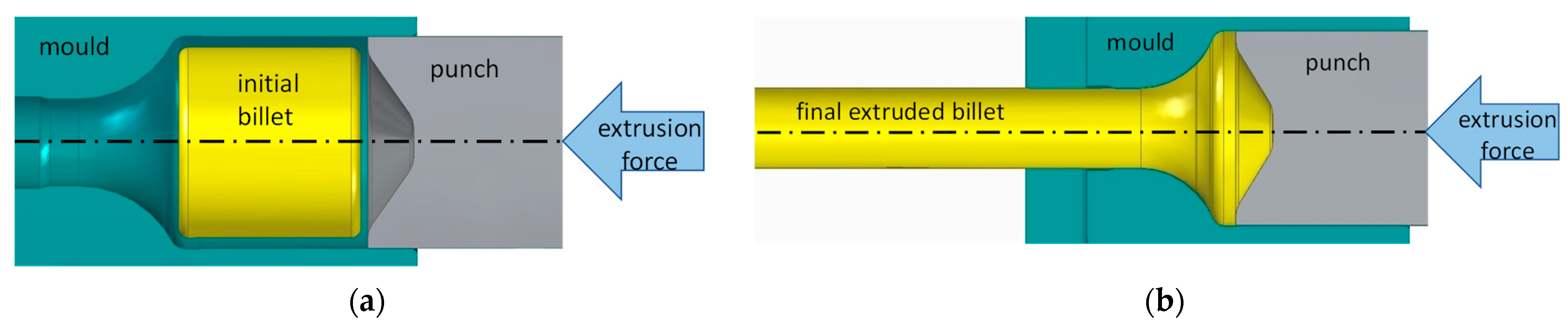
Abstract
:1. Introduction
2. Materials and Methods
2.1. Extrusion Process Set-Up
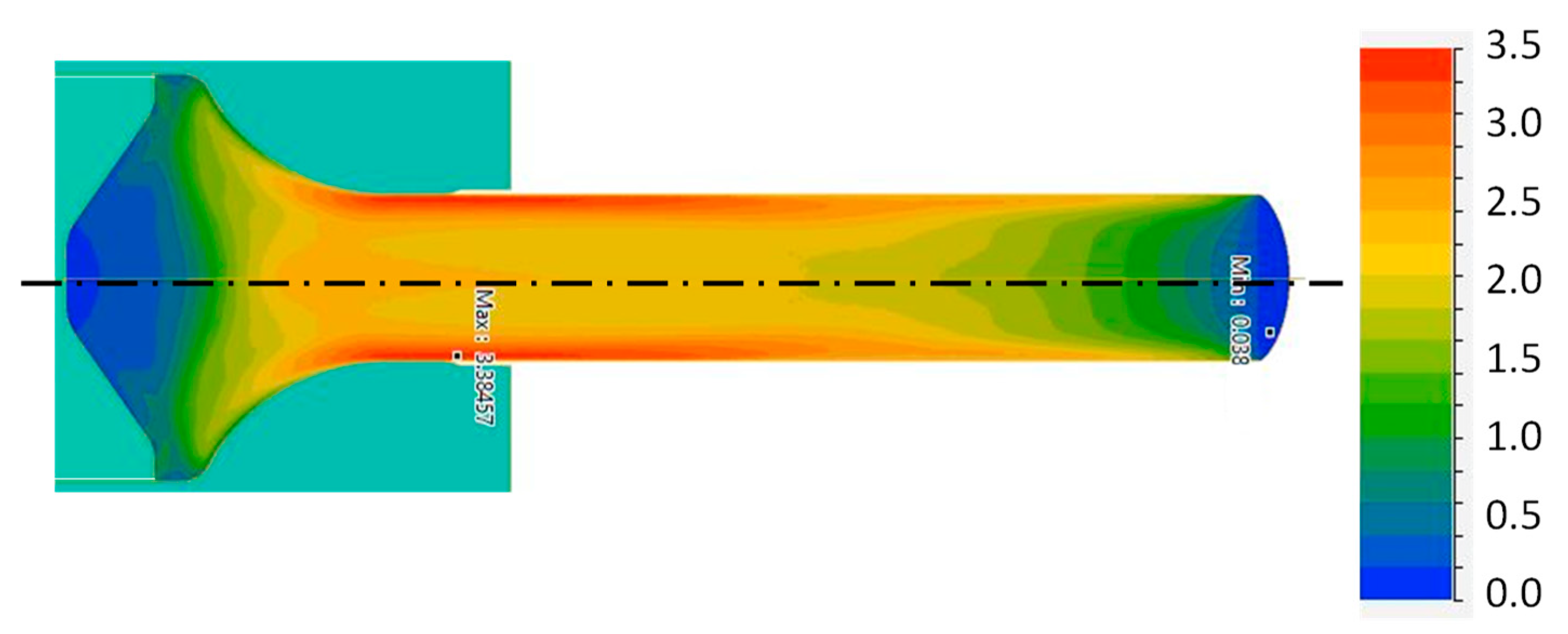
2.2. Process Simulation and Material Modelling
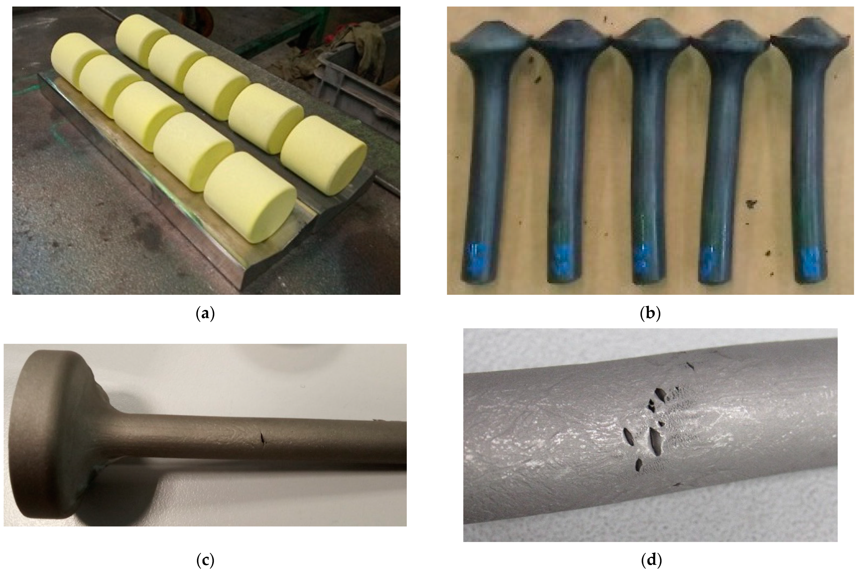
2.3. Extrusion Process Test
- The billet was heated to a temperature Tb (holding time 1500 s).
- The punch and mold were lubricated with a graphite and water mixture.
- The billet was transferred from the oven to the mold (duration time: 3 s).
- The billet was maintained in position for 3 s (in this phase, heat was transferred from the billet to the mold)
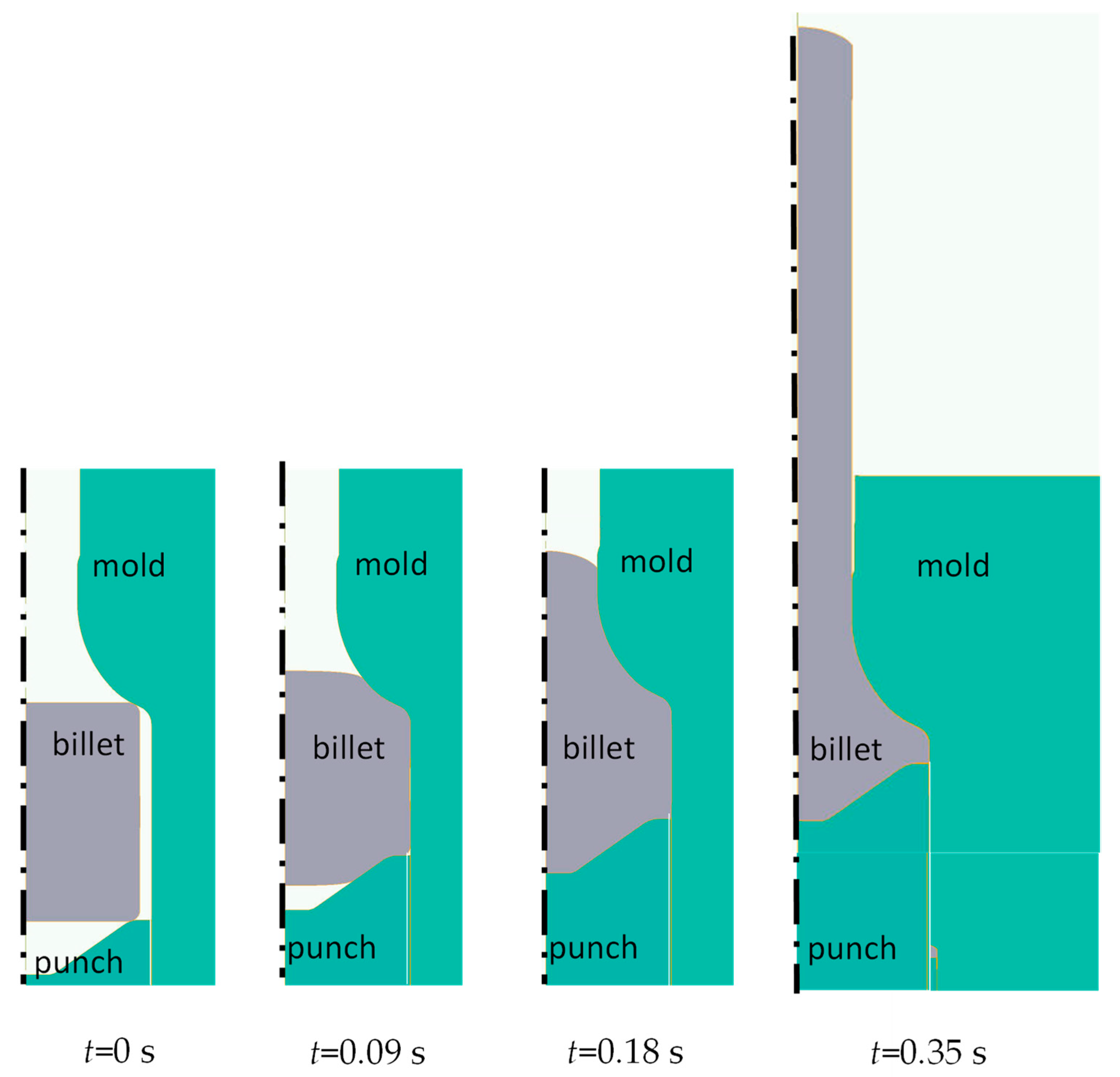
- The punch was moved forward to perform the extrusion of the billet at constant speed v.
- Finally, the punch was retracted and the extruded billet was extracted.
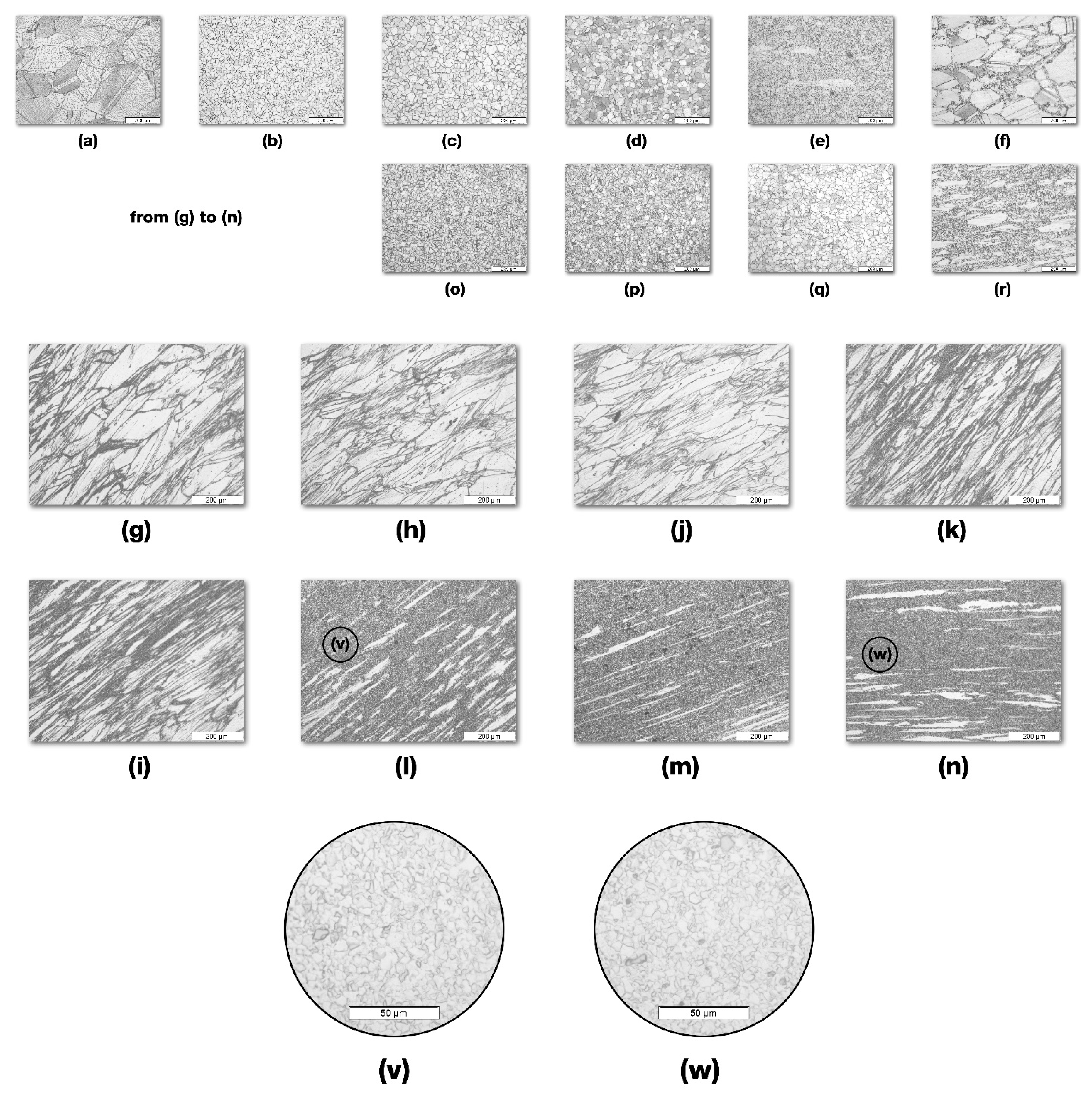
2.4. Macro and Micro-Structure Analysis
3. Results and Discussion
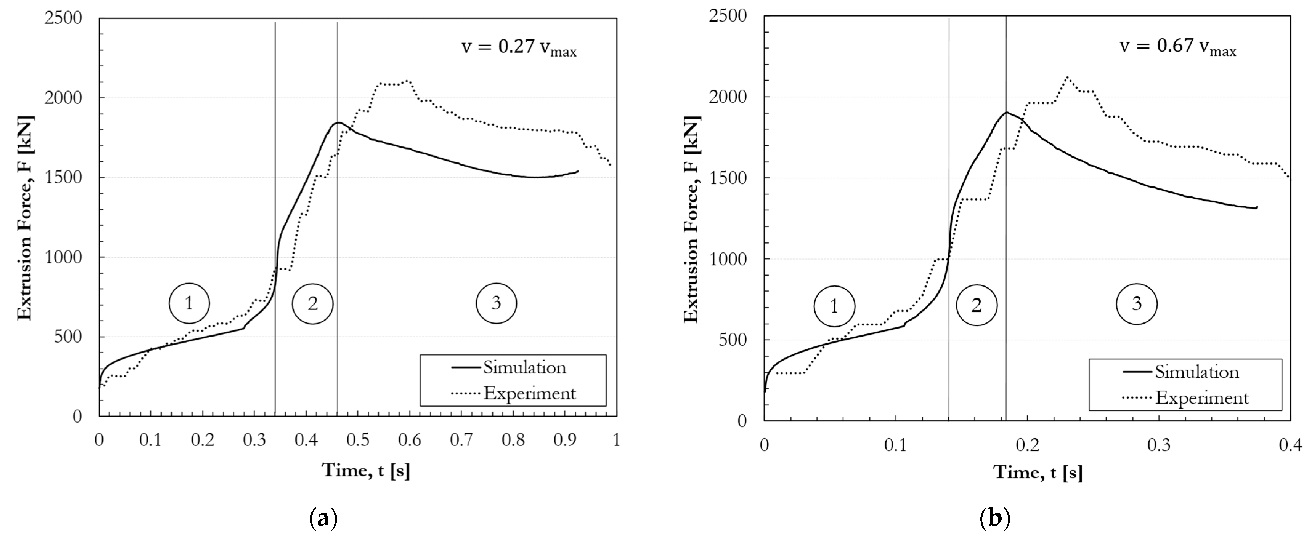
3.1. Extrusion Process and Force Evolution: Numerical Simulation and Experiments
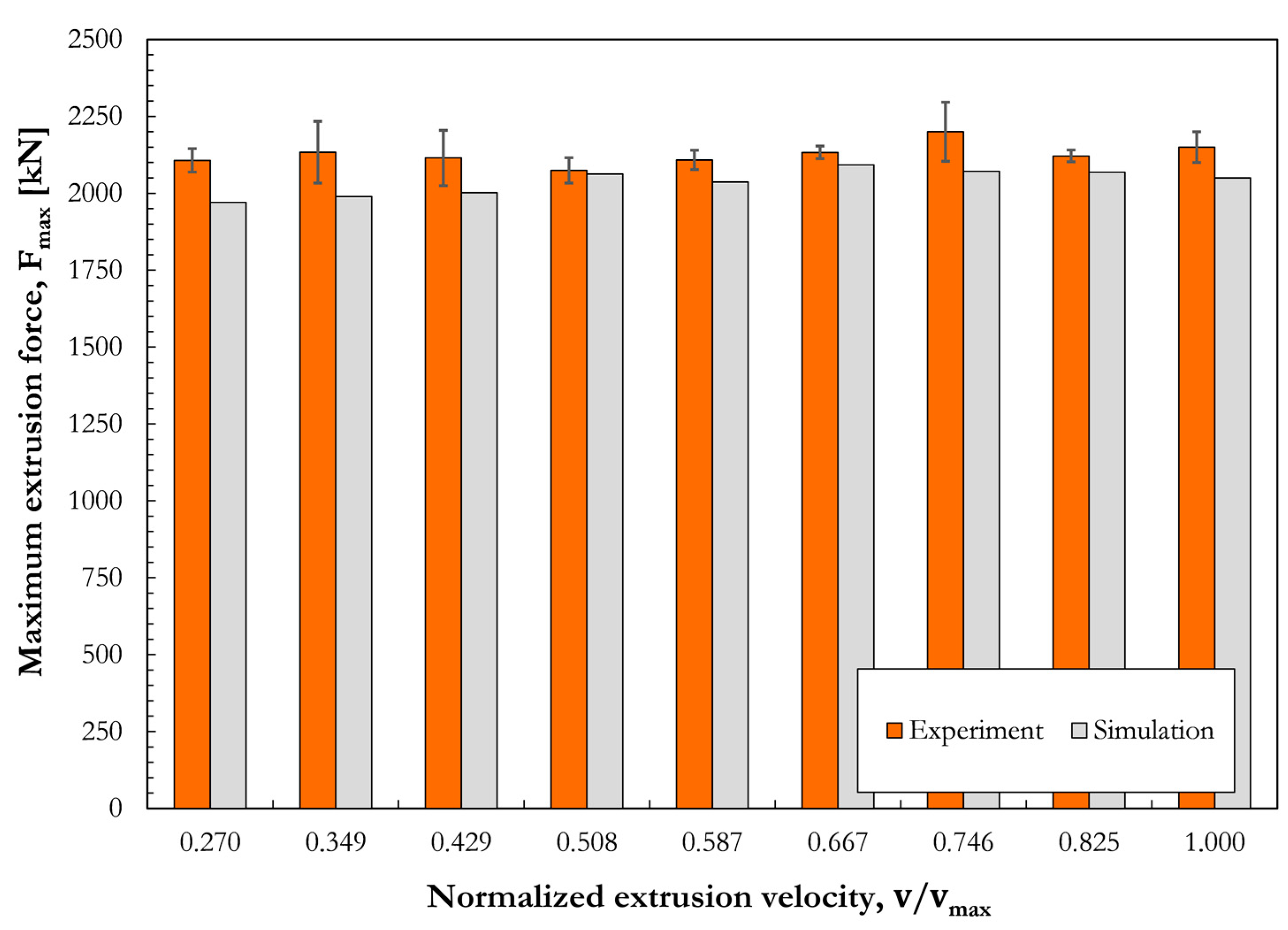
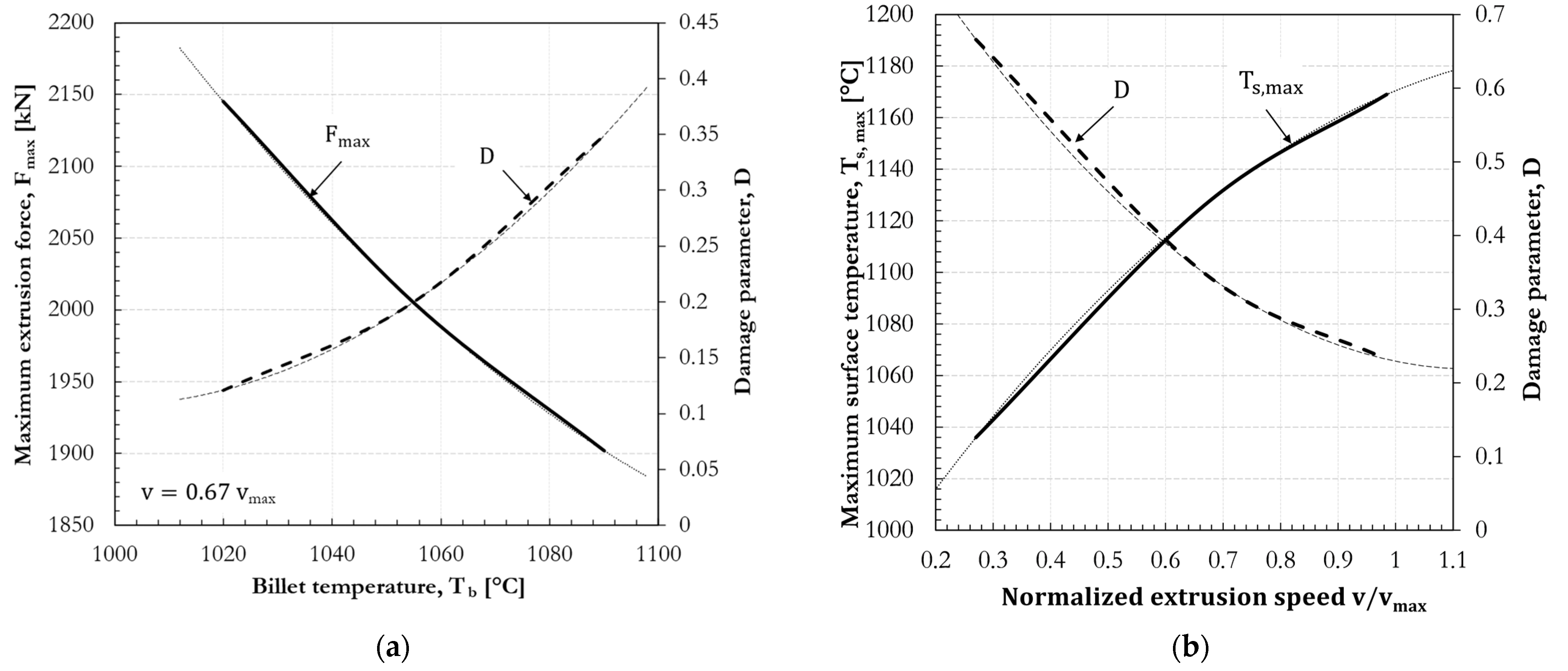
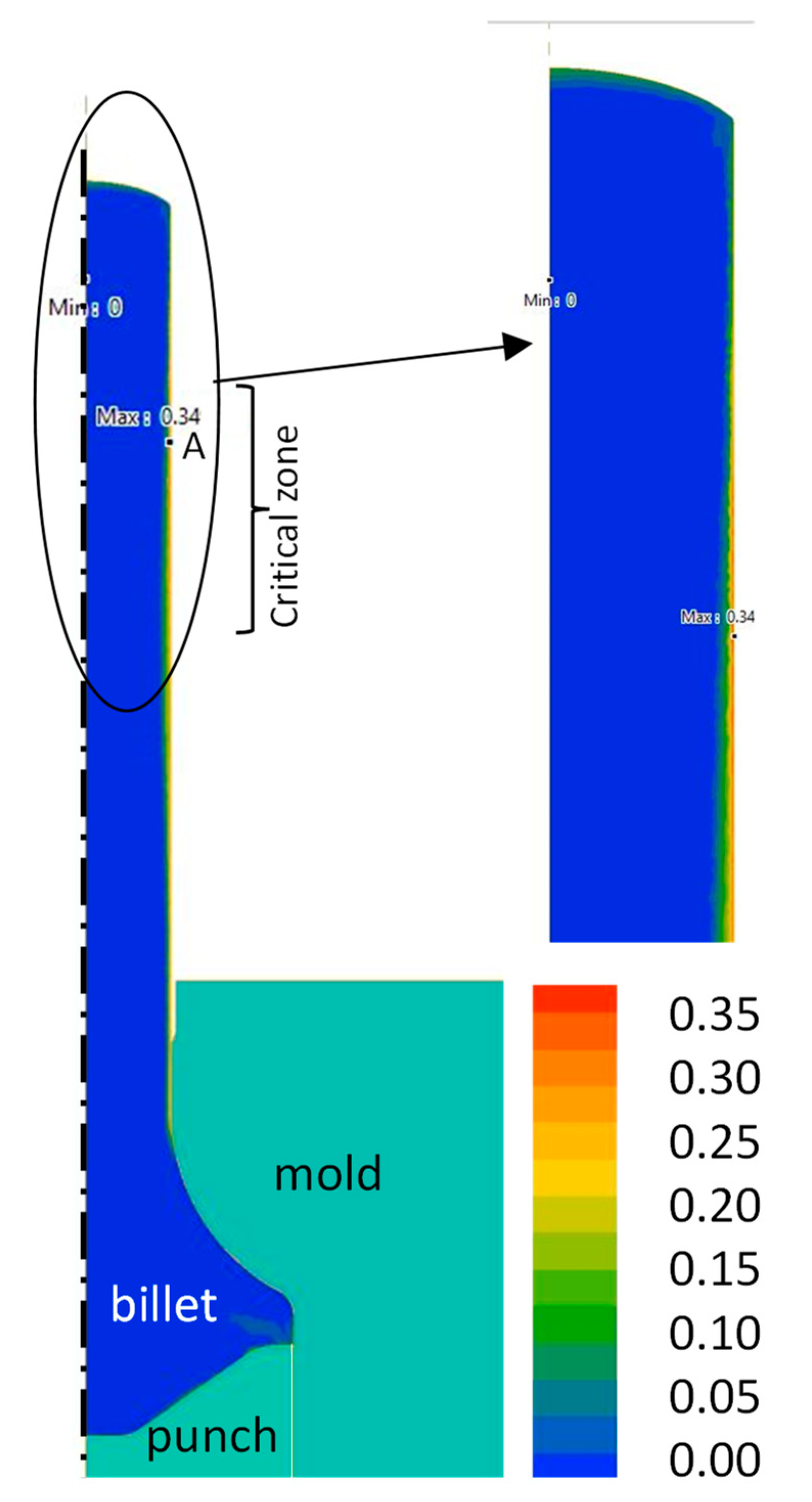
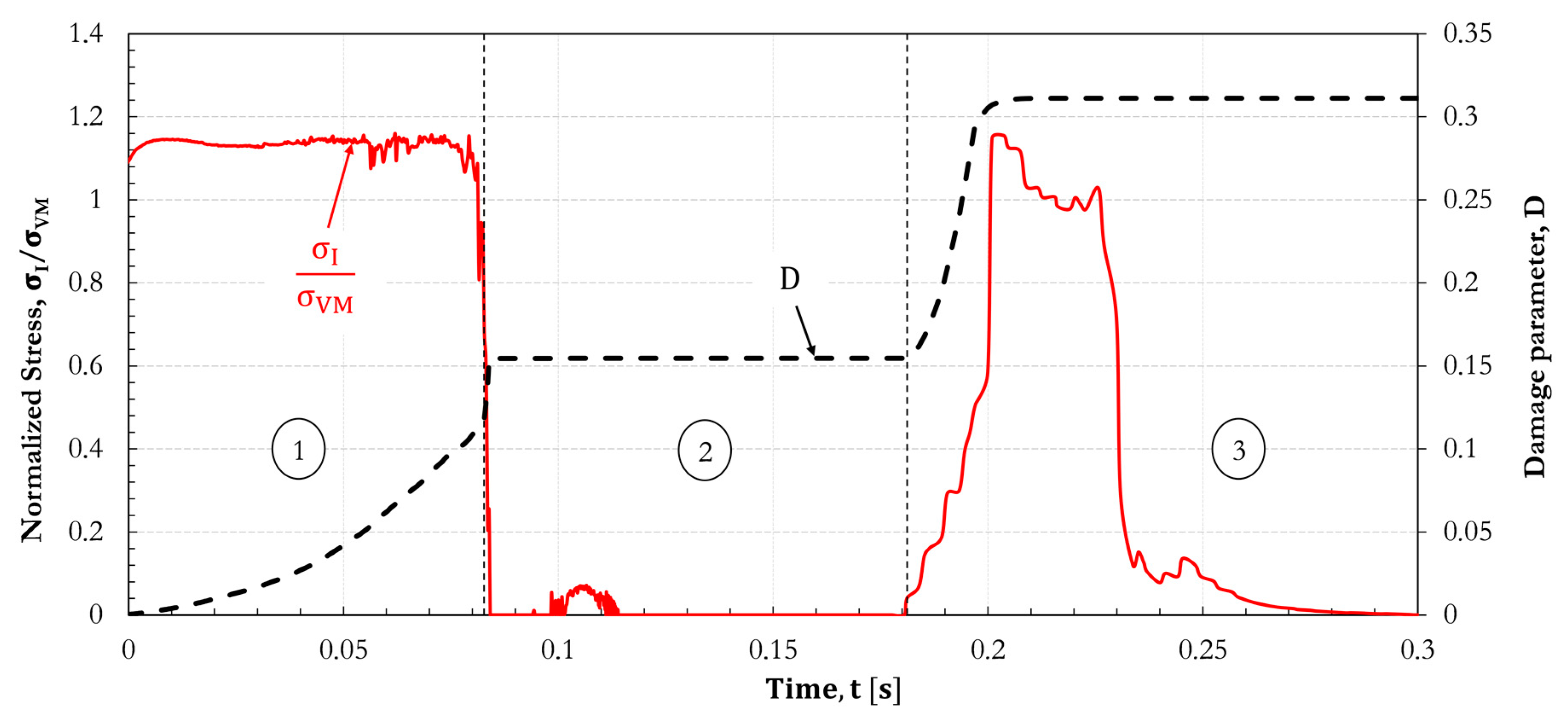
3.2. Parametrical Analyses and Surface Crack Formation
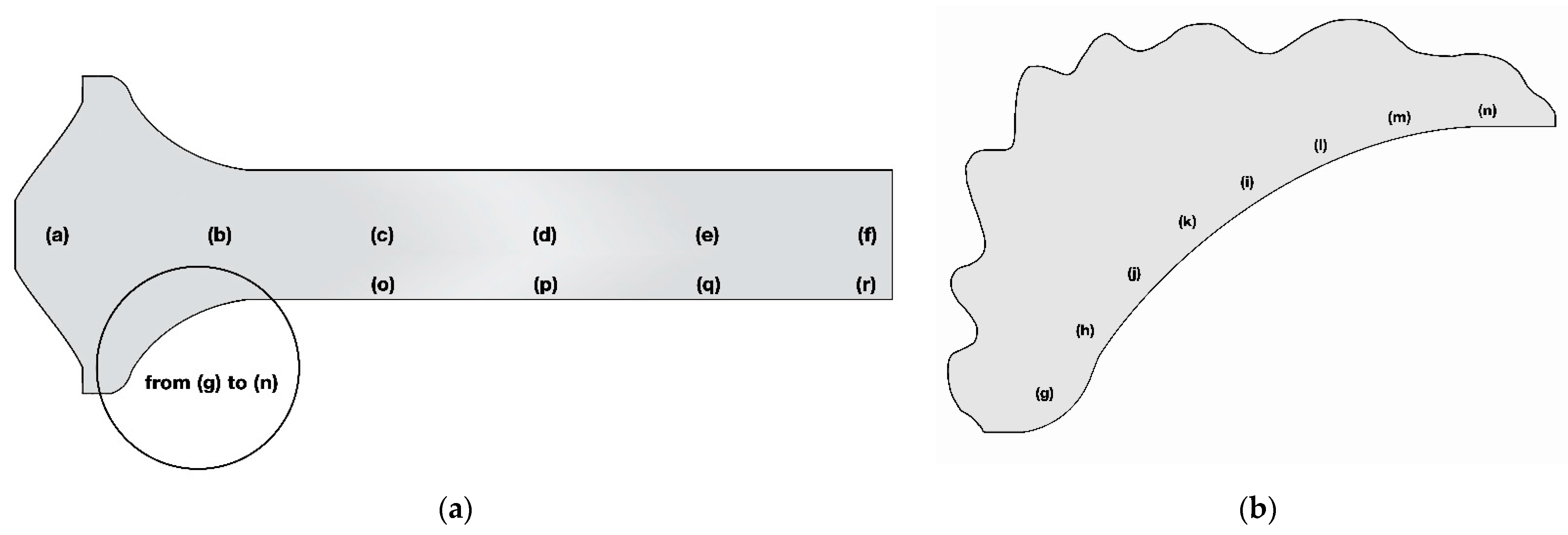
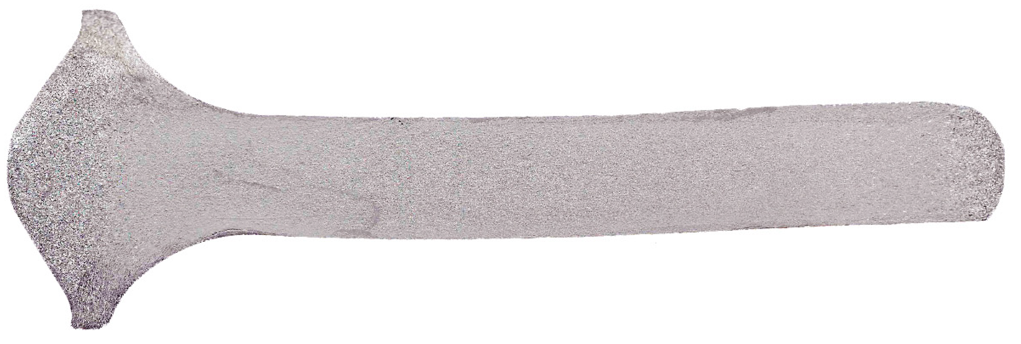
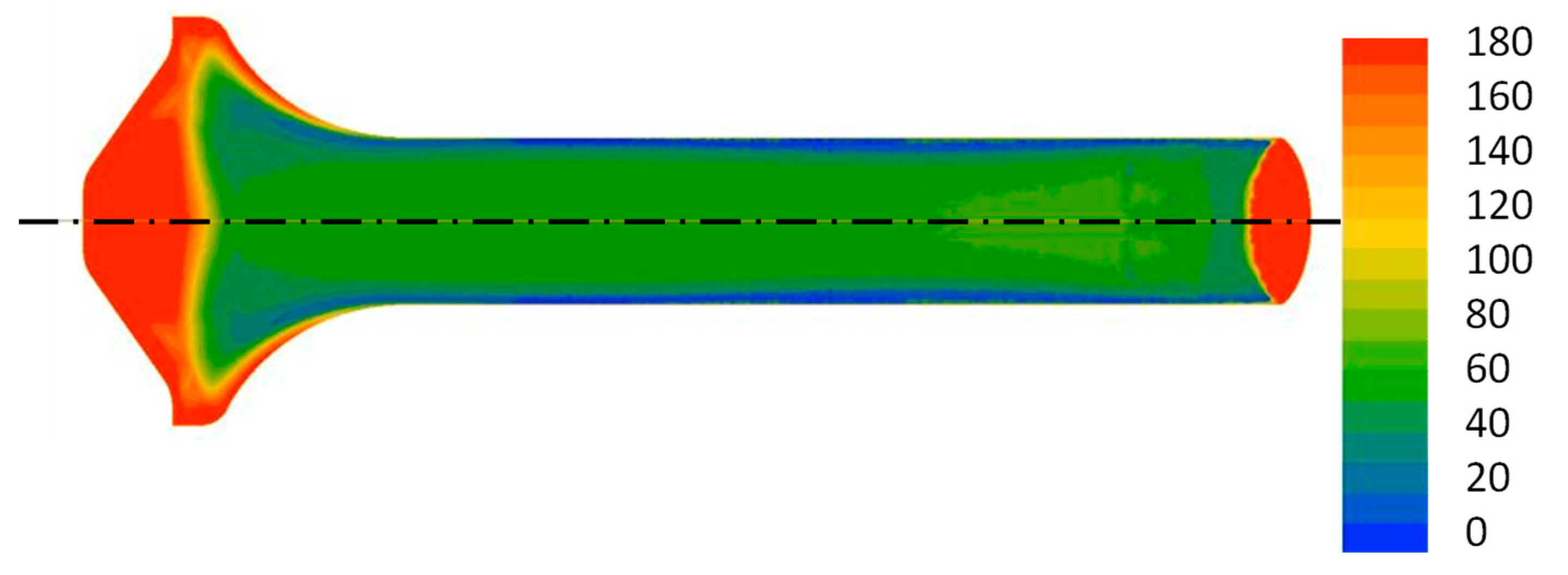
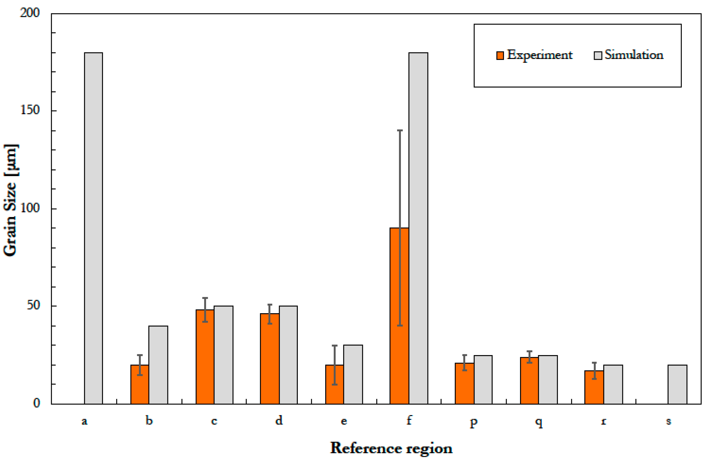
3.3. Experimental and Numerical Macro and Micro-Structure Analysis
4. Conclusions
Author Contributions
Funding
Data Availability Statement
Conflicts of Interest
References
- Salvati, E.; Lunt, A.J.G.; Ying, S.; Sui, T.; Zhang, H.J.; Heason, C.; Baxter, G.; Korsunsky, A.M. Eigenstrain reconstruction of residual strains in an additively manufactured and shot peened nickel superalloy compressor blade. Comput. Methods Appl. Mech. Eng. 2017, 320, 335–351. [Google Scholar] [CrossRef]
- Tang, Y.T.; Panwisawas, C.; Jenkins, B.M.; Liu, J.; Shen, Z.; Salvati, E.; Reed, R.C. Multi-length-scale study on the heat treatment response to supersaturated nickel-based superalloys: Precipitation reactions and incipient recrystallisation. Addit. Manuf. 2023, 62, 103389. [Google Scholar] [CrossRef]
- Qi, H. Review of inconel 718 alloy: Its history, properties, processing and developing substitutes. J. Mater. Eng. 2012, 2, 92–100. [Google Scholar]
- Rahman, M.; Seah, W.K.H.; Teo, T.T. The machinability of Inconel 718. J. Mater. Process. Technol. 1997, 63, 199–204. [Google Scholar] [CrossRef]
- Thakur, D.G.; Ramamoorthy, B.; Vijayaraghavan, L. Study on the machinability characteristics of superalloy Inconel 718 during high speed turning. Mater. Des. 2009, 30, 1718–1725. [Google Scholar] [CrossRef]
- Felusiak-Czyryca, A.; Madajewski, M.; Twardowski, P.; Wiciak-Pikuła, M. Cutting forces during Inconel 718 orthogonal turn-milling. Materials 2021, 14, 6152. [Google Scholar] [CrossRef]
- De Bartolomeis, A.; Newman, S.T.; Jawahir, I.S.; Biermann, D.; Shokrani, A. Future research directions in the machining of Inconel 718. J. Mater. Process. Technol. 2021, 297, 117260. [Google Scholar] [CrossRef]
- Gordine, J. Some problems in welding Inconel 718. WELD J. 1971, 50, 480–484. [Google Scholar]
- Chen, J.; Salvati, E.; Uzun, F.; Papadaki, C.; Wang, Z.; Everaerts, J.; Korsunsky, A.M. An experimental and numerical analysis of residual stresses in a TIG weldment of a single crystal nickel-base superalloy. J. Manuf. Process. 2020, 53, 190–200. [Google Scholar] [CrossRef]
- Tharappel, J.T.; Babu, J. Welding processes for Inconel 718-A brief review. IOP Conf. Ser. Mater. Sci. Eng. 2018, 330, 012082. [Google Scholar] [CrossRef]
- Salvati, E.; Lunt, A.J.; Heason, C.P.; Baxter, G.J.; Korsunsky, A.M. An analysis of fatigue failure mechanisms in an additively manufactured and shot peened IN 718 nickel superalloy. Mater. Des. 2020, 191, 108605. [Google Scholar] [CrossRef]
- Trosch, T.; Strößner, J.; Völkl, R.; Glatzel, U. Microstructure and mechanical properties of selective laser melted Inconel 718 compared to forging and casting. Mater. Lett. 2016, 164, 428–431. [Google Scholar] [CrossRef]
- Hu, L.; Shi, K.; Luo, X.; Yu, J.; Ai, B.; Liu, C. Application of additively manufactured pentamode metamaterials in sodium/Inconel 718 heat pipes. Materials 2021, 14, 3016. [Google Scholar] [CrossRef] [PubMed]
- Wu, K.; Chee, S.W.; Sun, W.; Tan, A.W.-Y.; Tan, S.C.; Liu, E.; Zhou, W. Inconel 713C Coating by cold spray for surface enhancement of Inconel 718. Metals 2021, 11, 2048. [Google Scholar] [CrossRef]
- Bauccio, M. ASM Metals Handbook Vol. 14: Forming and Forging, 9th ed.; ASM International: Tokyo, Japan, 1996. [Google Scholar]
- De Jaeger, J.; Solas, D.; Baudin, T.; Fandeur, O.; Schmitt, J.H.; Rey, C. Inconel 718 single and multipass modelling of hot forging. In Superalloys 2012: 12th International Symposium on Superalloys; John Wiley & Sons Inc.: Chichester, UK, 2012; pp. 663–672. [Google Scholar]
- Chamanfar, A.; Sarrat, L.; Jahazi, M.; Asadi, M.; Weck, A.; Koul, A.K. Microstructural characteristics of forged and heat treated Inconel-718 disks. Mater. Des. 2013, 52, 791–800. [Google Scholar] [CrossRef]
- Jackman, L.A. Forming and Fabrication of Superalloys. In Proceedings of the Symposium on Properties of High Temperature Alloys, Las Vegas, NV, USA, 18–21 October 1976; pp. 42–58. [Google Scholar]
- Duan, X.; Velay, X.; Sheppard, T. Application of finite element method in the hot extrusion of aluminium alloys. Mater. Sci. Eng. A 2004, 369, 66–75. [Google Scholar] [CrossRef]
- Nielsen, C.V.; Martin, P.A.F. Metal Forming: Formability, Simulation, and Tool Design, 1st ed.; Academic Press: London, UK, 2021. [Google Scholar]
- Moro, L.; Srnec Novak, J.; Benasciutti, D.; De Bona, F. Thermal distortion in copper moulds for continuous casting of steel: Numerical study on creep and plasticity effect. Ironmak. Steelmak. 2019, 46, 97–103. [Google Scholar] [CrossRef]
- De Bona, F.; Novak, J.S.; Lanzutti, A.; Lucacci, G. Distortion after solubilization treatment of X12CrNiMoV12-3 beam-like samples: A novel FE modelling technique supported by experiments. Eng. Fail. Anal. 2022, 135, 106141. [Google Scholar] [CrossRef]
- Biba, N.; Borowikow, A.; Wehage, D. Simulation of recrystallisation and grain size evolution in hot metal forming. AIP Conf. Proc. 2011, 1353, 127–132. [Google Scholar]
- Zinkiewitcz, O.C. Flow formulation for numerical solution of metal forming processes. In Numerical Analysis of Forming Processes; Pittman, J.F.T., Zienkiewicz, O.C., Woof, R.D., Alexander, J.M., Eds.; Wiley: Chichester, UK, 1984; pp. 1–44. [Google Scholar]
- Levanov, A.N.; Kolmogorov, V.L.; Burkin, S.P.; Kartak, B.R.; Ashpur Yu, V.; Spassky Yu, I. Kontaktnoe Trenie v Protsessakh Obrabotki Metallov Davleniem (Contact Friction in Metal Forming Processes); Metallurgiya Publish: Moscow, Russia, 1976. [Google Scholar]
- ASM Handbook Vol. 2: Properties and Selection: Nonferrous Alloys and Special-Purpose Materials; ASM International: Tokyo, Japan, 1990.
- Sui, F.L.; Xu, L.X.; Chen, L.Q.; Liu, X.H. Processing map for hot working of Inconel 718 alloy. J. Mater. Process. Technol. 2011, 211, 433–440. [Google Scholar] [CrossRef]
- Thomas, A.; El-Wahabi, M.; Cabrera, J.M.; Prado, J.M. High temperature deformation of Inconel 718. J. Mater. Process. Technol. 2006, 177, 469–472. [Google Scholar] [CrossRef]
- Frost, H.J.; Ashby, M.F. Deformation—Mechanism Maps. The Plasticity and Creep of Metals and Ceramics; Pergamon Press: Oxford, UK, 1982; pp. 54–55. [Google Scholar]
- Mahalle, G.; Kotkunde, N.; Gupta, A.K.; Singh, S.K. Comparative assessment of failure strain predictions using ductile damage criteria for warm stretch forming of IN718 alloy. J. Mater. Form. 2021, 14, 799–812. [Google Scholar] [CrossRef]
- Cockcroft, M.G.; Latham, D.J. Ductility and the workability of metals. J. Inst. Met. 1968, 96, 33–39. [Google Scholar]
- Clift, S.E.; Hartley, P.; Sturgess, C.E.N.; Rowe, G.W. Fracture prediction in plastic deformation processes. Int. J. Mech. Sci. 1990, 32, 1–17. [Google Scholar] [CrossRef]
- Jafarian, F.; Ciaran, M.I.; Umbrello, D.; Arrazola, P.J.; Filice, L.; Amirabadi, H. Finite element simulation of machining Inconel 718 alloy including microstructure changes. Int. J. Mech. Sci. 2014, 88, 110–121. [Google Scholar] [CrossRef]
- Stebunov, S.; Vlasov, A.; Biba, N. Prediction of fracture in cold forging with modified Cockcroft-Latham criterion. Procedia Manuf. 2018, 15, 519–526. [Google Scholar] [CrossRef]
- Sellars, C.M.; Whiteman, J.A. Recrystallization and grain growth in hot rolling. Met. Sci. 1979, 13, 187–194. [Google Scholar] [CrossRef]
- Biba, N.; Stebunov, S.; Vlasov, A. Material forming simulation environment based on QForm3D software system. Energy 2017, 2, 4. [Google Scholar]
- Na, Y.S.; Yeom, J.T.; Park, N.K.; Lee, J.Y. Prediction of microstructure evolution during high temperature blade forging of a Ni−Fe based superalloy 718. Met. Mater. Int. 2003, 9, 15–19. [Google Scholar] [CrossRef]
- Gruber, C.; Raninger, P.; Stanojevic, A.; Godor, F.; Rath, M.; Kozeschnik, E.; Stockinger, M. Simulation of dynamic and meta-dynamic recrystallization behavior of forged alloy 718 Parts using a multi-class grain size model. Materials 2021, 14, 111. [Google Scholar] [CrossRef]
- Soufian, E.; Darabi, R.; Abouridouane, M.; Reis, A.; Bergs, T. Numerical predictions of orthogonal cutting–induced residual stress of super alloy Inconel 718 considering dynamic recrystallization. Int. J. Adv. Manuf. Technol. 2022, 122, 601–617. [Google Scholar] [CrossRef]
- Churyumov, A.Y.; Pozdniakov, A.V. Simulation of microstructure evolution in metal materials under hot plastic deformation and heat treatment. Phys. Metals Metallogr. 2020, 121, 1064–1086. [Google Scholar] [CrossRef]
- Churyumov, A.Y.; Pozdnyakov, A.V.; Churyumova, T.A.; Cheverikin, V.V. Hot plastic deformation of heat-resistant austenitic aisi 310s steel. Part 1. simulation of flow stress and dynamic recrystallization. Chernye Met. 2020, 9, 48–55. [Google Scholar]


Disclaimer/Publisher’s Note: The statements, opinions and data contained in all publications are solely those of the individual author(s) and contributor(s) and not of MDPI and/or the editor(s). MDPI and/or the editor(s) disclaim responsibility for any injury to people or property resulting from any ideas, methods, instructions or products referred to in the content. |
© 2023 by the authors. Licensee MDPI, Basel, Switzerland. This article is an open access article distributed under the terms and conditions of the Creative Commons Attribution (CC BY) license (https://creativecommons.org/licenses/by/4.0/).
Share and Cite
Bacchetti, S.; Coppola, M.A.; De Bona, F.; Lanzutti, A.; Miotti, P.; Salvati, E.; Sordetti, F. Experimental and Numerical Investigation of Hot Extruded Inconel 718. Metals 2023, 13, 1129. https://doi.org/10.3390/met13061129
Bacchetti S, Coppola MA, De Bona F, Lanzutti A, Miotti P, Salvati E, Sordetti F. Experimental and Numerical Investigation of Hot Extruded Inconel 718. Metals. 2023; 13(6):1129. https://doi.org/10.3390/met13061129
Chicago/Turabian StyleBacchetti, Stefano, Michele A. Coppola, Francesco De Bona, Alex Lanzutti, Pierpaolo Miotti, Enrico Salvati, and Francesco Sordetti. 2023. "Experimental and Numerical Investigation of Hot Extruded Inconel 718" Metals 13, no. 6: 1129. https://doi.org/10.3390/met13061129