Article

Flux Weakening Controller Design for Series-Winding Three-Phase PMSM Drive Systems

School of Energy and Environment, City University of Hong Kong, Hong Kong, China
*
Author to whom correspondence should be addressed.
World Electr. Veh. J. 2023, 14(4), 107; https://doi.org/10.3390/wevj14040107
Submission received: 12 March 2023 / Revised: 30 March 2023 / Accepted: 10 April 2023 / Published: 13 April 2023

Abstract

:
Series-winding three-phase PMSMs have a higher bus voltage utilization than the conventional three-phase PMSMs with star connection. This topology is suitable for applications with a limited bus voltage. However, the zero-sequence current controller will reduce the bus voltage utilization of the series-winding PMSMs, which causes problems in the flux-weakening controller design. The conventional flux-weakening control algorithms will cause the series-winding PMSMs to enter the overmodulation region early and degrade the performance of the zero-sequence current suppression algorithm. In this paper, a new flux-weakening controller with a dynamic fundamental voltage limit (FW-DFVL) is designed for the series-winding three-phase PMSM traction system. Firstly, the space vector modulation method combines the proposed virtual zero-sequence vectors to realize both the fundamental current generation and the zero-sequence current suppression. The accurate bus voltage utilization in the fundamental current subspace can be derived from the proposed modulation method. Secondly, the gradient descent method generates the flux-weakening d-axis reference current with the dynamic fundamental voltage, which will converge faster than the conventional PI-based flux-weakening control scheme. Thirdly, the flux-weakening controller in the overmodulation region is also designed where the zero-sequence current will no longer be suppressed. The bus voltage utilization is Vdc in this operation mode. Finally, both the simulation and experimental results are utilized to verify the effectiveness of the proposed FW-DFVL, where faster dynamic performance and higher bus utilization are observed.

1. Introduction

The emerging magnetic-field-modulated motor design [1] and the high bus voltage utilization drive topologies [2] will promote the use of permanent magnet synchronous motor (PMSM) drive systems in low-speed and high-torque applications such as the servo motor drive system [3] and electrical vehicles [4].
Among these new drive topologies, the series-winding PMSM [5,6] is suitable for electric vehicles because of its higher bus utilization and better fault-tolerant capability. Moreover, the concept of series-winding PMSM can be combined with the multiphase PM machines to obtain the advantages of both higher torque density and bus voltage utilization [7,8].
The flux-weakening control algorithms are necessary to extend the operating speed range of PMSMs [9,10]. The central concept of the flux-weakening control scheme is to reduce the active flux in the rotor by negative d-axis currents to keep the PMSM operating over the rated speed [11] (with the fixed bus voltage). This concept has been widely applied in the conventional three-phase PMSM [12].
Generally, the flux-weakening control scheme in the three-phase PMSM is divided into two types. The first concept is the feedback method, where the reference d-axis current is determined according to the residual between the fundamental voltage limit and required voltage amplitude [13,14]. These control strategies do not depend on the motor parameters and have excellent steady-state performance [15,16].
Another concept is the feedforward method [17], where the flux-weakening current is calculated directly. However, these controllers always neglect the voltage drop caused by the resistance [18]. Moreover, the parameter mismatches will degrade algorithm performance [19]. In contrast, the fast dynamic performance of feedforward methods is preferred in traction systems. Some hybrid approaches have been developed to obtain fast dynamic performance and good steady-state performance [20,21].
However, the existing research on the flux-weakening controller applied in the conventional three-phase PMSM with star connection only utilizes the fixed value as the voltage limit [22]. In contrast, the fundamental voltage limit in the series-winding PMSM is not a constant [23]. Compared with the three-phase PMSM, there is an additional zero-sequence loop in the series-winding PMSM [24]. Since the zero-sequence currents generally do not produce electromagnetic torque, most literature suppresses the zero-sequence currents to reduce the copper losses [25]. Thus, the controller realizes both the fundamental current generation and the zero-sequence current (ZSC) suppression. In this case, the fundamental voltage limit will be affected by the zero-sequence voltage (ZSV) amplitude.
Similarly, the harmonic currents are always suppressed in the multiphase PMSMs to reduce the copper losses [26,27]. Thus, the bus voltage utilization of multiphase PMSM controllers is also affected by the harmonic current controller [28,29]. The degradation in bus voltage utilization is inevitable in PM machines with an additional current loop [30]. Suppose the improper bus voltage limit is applied in the conventional PI-based flux-weakening controller, the larger d-axis current or the distorted phase currents will cause additional copper losses [31,32].
In this paper, the flux-weakening control strategy for series-winding PMSM is designed. Firstly, a new modulation method is provided where the accurate fundamental voltage limit is expressed as the function of the required ZSV. Secondly, the gradient descent method solves the reference flux-weakening current in real time. Finally, the overmodulation method of series-winding PMSM will be discussed to extend the operation region further. Both the simulation and experimental results verify the effectiveness of the proposed strategy.

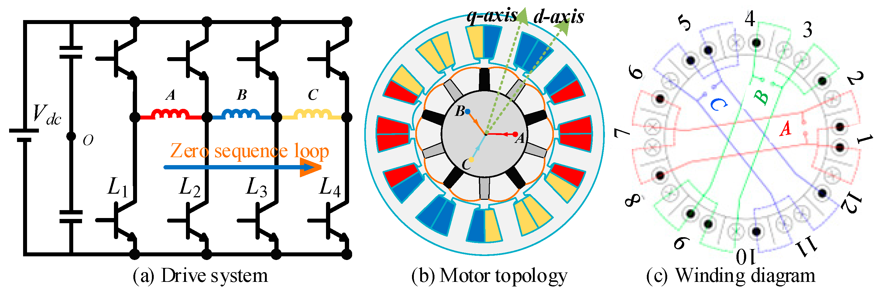
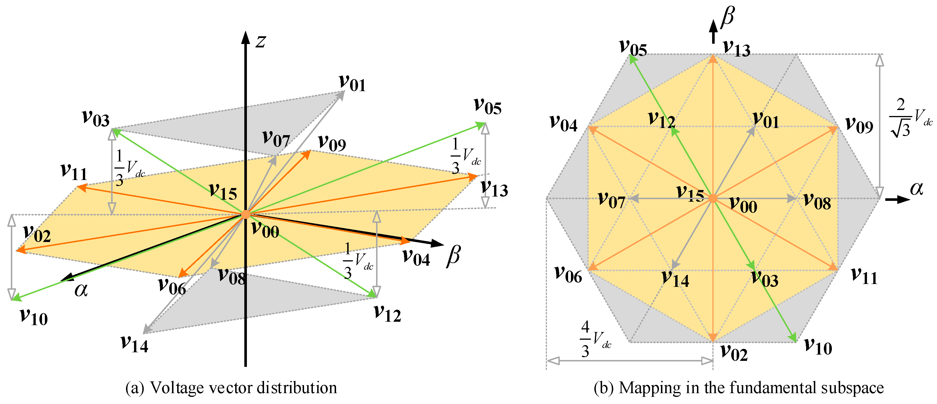
2. Topology of Series-Winding PMSM Drive System

This section introduces the topology and mathematical model of the series-winding PMSM drive system. The drive system of series-winding PMSM is shown in Figure 1, where four half-bridges drive the phase winding of three-phase PMSM. In the series-winding permanent magnet synchronous motor (PMSM), there are three distinct current axes. The z-axis represents the zero-sequence loop, as shown in Figure 1a, and the zero-sequence inductance describes the motor windings’ ability to store energy in a magnetic field common to all three phases of the motor. The d-axis (also known as the direct axis) is a reference axis that corresponds to the motor’s magnetic pole axis. Typically, the d-axis coincides with the motor’s rotor axis, as depicted in Figure 1b. The q-axis (also known as the quadrature axis) is another reference axis that is perpendicular to the d-axis. The q-axis is oriented at a 90-degree electrical angle to the d-axis, which means that it is perpendicular to the direction of the motor’s magnetic poles, as shown in Figure 1b.
There is a mapping between phase and half-bridge currents, phase voltages, and half-bridge switching states.
Firstly, the transformation matrix between the half-bridge currents to the phase currents is shown in Equation (1). With this transformation, the phase currents are reconstructed from the half-bridge currents [33].
i a i b i c = 1 0 0 0 1 1 0 0 1 1 1 0 i l 1 i l 2 i l 3 i l 4
where ia, ib, and ic are the phase currents, and il1, il2, il3, and il4 are the currents in four half-bridges.
Secondly, the phase voltages are also obtained from the duty cycles of four half-bridges. The mapping relationship is expressed as:
u a u b u c = 1 1 0 0 0 1 1 0 0 0 1 1 d l 1 d l 2 d l 3 d l 4
where ua, ub, and uc are the phase voltages, and dl1, dl2, dl3, and dl4 are the duty cycles of four half-bridges.
According to Equations (1) and (2), the phase voltages and currents of series-winding PMSM are obtained from voltages and currents in four half-bridges. Then, the voltage equation of the series-winding PMSM is described in the fundamental subspace and zero-sequence loop.
The Clarke transform decouples the phase components into the orthogonal coordinate subspace and the zero-sequence loop as shown in Equation (3).
F α F β F z = 2 3 1 1 2 1 2 0 3 2 3 2 1 2 1 2 1 2 F a F b F c
where F* represents voltage or current.
Then, these components are further decoupled into the rotating coordinate system as shown in Equation (4).
F d F q F z = c o s θ e s i n θ e 0 s i n θ e c o s θ e 0 0 0 1 F α F β F z
where θe is the electrical angle of the rotor.
The voltage equation is established in the dqz subspace and expressed as [34]:
u d u q u z = R s i d i q i z + L d 0 0 0 L q 0 0 0 L z d d t i d i q i z + ω e L q i q L d i d + ψ f 3 ψ f 3 sin 3 θ e
where ψf and ψf3 are the fundamental and third harmonic rotor flux, Rs denotes the stator resistance, Ld, Lq, and Lz denote the d-axis, q-axis, and z-axis inductance, and ωe denotes the rotor electrical angle speed.
The electromagnetic torque is:
T e = 1.5 n p ψ f i q + L d L q i d i q
where np is the number of pole pairs.
Finally, there are 16 voltage vectors in the series-winding PMSM. The distribution of these voltage vectors is shown in Figure 2a, where the voltage vectors have components in both the fundamental subspace and the zero-sequence loop. Moreover, Figure 2b provides the mapping of these voltage vectors in the fundamental subspace. The yellow area is the fundamental voltage subspace without ZSV.

3. Conventional Flux-Weakening Strategy

In this section, the conventional flux-weakening control strategy is introduced. Since there is no literature on the flux-weakening control strategy of series-winding PMSM, we will introduce the conventional flux-weakening control algorithm for three-phase PMSM [23] and combine it with the existing current control algorithm for series-winding PMSM [30].
The total control diagram is shown in Figure 3, divided into three parts. The first part is the outer speed loop, where the q-axis current reference is determined by the residual error between the reference speed and the actual speed.
The second part is the flux-weakening control section, where the reference d-axis current is determined by a PI controller. If the required fundamental voltage amplitude exceeds the fundamental voltage limit, this PI controller will adjust the reference d-axis current to ensure the feasible fundamental voltage vector [35]. It needs to be mentioned that the fundamental voltage limit in the conventional flux-weakening control scheme is constant and equal to Vdc.
The third part is the current control section. The voltage reference is determined by the residual error between the reference current from the first and second parts and the actual current from sensors. Then, according to the voltage reference, the space vector modulation method [30] will be applied to generate the duty cycle of four bridges. The carrier-based pulse-width modulation (CBPWM) [8] can also be utilized to generate the duty cycles of four half-bridges.
The main problem of the conventional flux-weakening controller is the inaccurate fundamental voltage limit. Since the suppression of ZSC requires the utilization of additional voltage vectors, the fundamental voltage limit cannot reach Vdc and will vary in real-time. This inaccurate fundamental voltage limit will increase total harmonic distortion (THD) and worsen the performance [36].

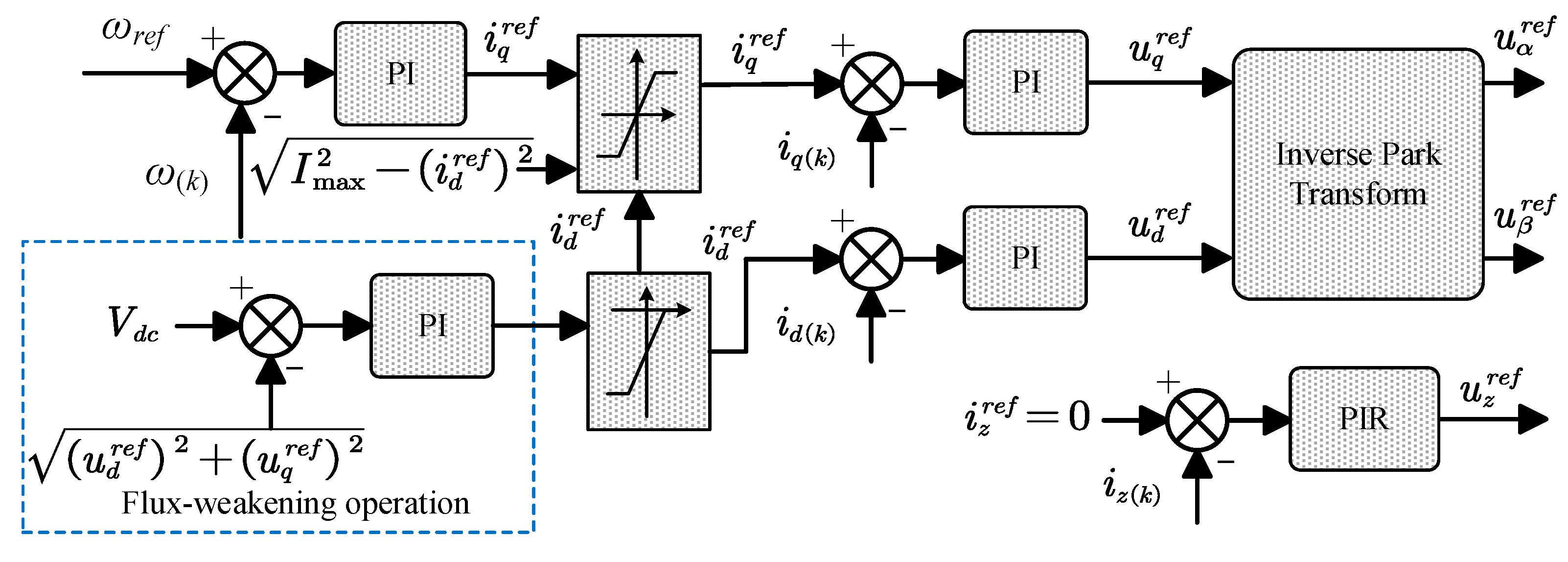
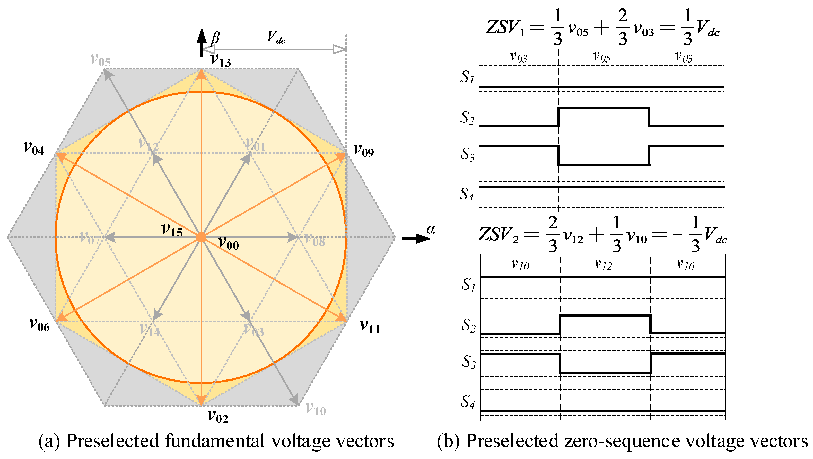
4. Proposed Improved Flux-Weakening Control Strategy

This section will introduce an improved flux-weakening control strategy with a dynamic fundamental voltage limit. The purpose of this control algorithm is to avoid the performance degradation of the controller in the flux-weakening operation region caused by the inaccurate fundamental voltage limit.

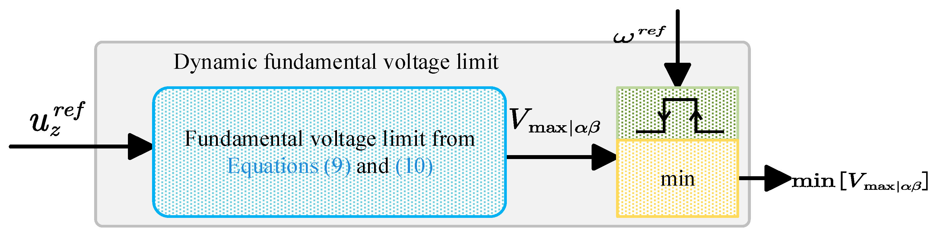
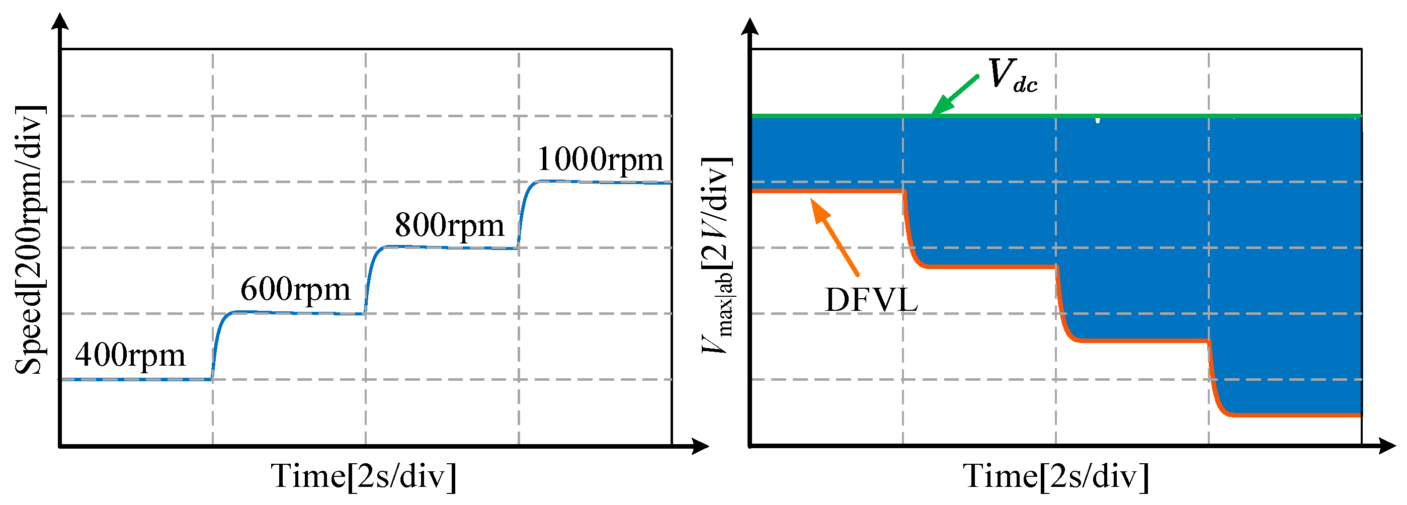
4.1. Dynamic Fundamental Voltage Limit

The fundamental voltage limit considering ZSV is derived in this subsection. The improved modulation methods are proposed to obtain an accurate fundamental voltage limit. The basic voltage vectors in Figure 2 are divided into two parts. The first part is the fundamental voltage vectors, as shown in Figure 4a. These voltage vectors have no components in the zero-sequence loop. The second part is the zero-sequence voltage vectors, as shown in Figure 4b, with no fundamental subspace components. The yellow area is the fundamental voltage vectors without ZSV.
The first virtual zero-sequence vector ZSV1 is expressed as:
Z S V 1 = 1 3 v 05 + 2 3 v 03 = 1 3 V d c
Similarly, v12 and v10 can also generate the second virtual zero-sequence vector ZSV2 as:
Z S V 2 = 2 3 v 12 + 1 3 v 10 = 1 3 V d c
The preselected fundamental voltage vectors and the virtual zero-sequence voltage vectors are combined to generate the required voltage vectors in the modulation process. Then, the synchronized switching signals should be designed. For instance, a voltage vector with the positive zero-sequence voltage vector is shown in Figure 5a. The switching signals on the left (orange) represent the fundamental voltage vectors, and the switching signals on the right (green) represent the virtual zero-sequence voltage vectors.
Then, the synchronized switching signals are shown in Figure 5b to avoid the increasing switching frequency. The high-level switching signals in one cycle will be added and generated as a standard PWM wave.
Finally, the maximum linear fundamental voltage limit can be obtained from Figure 5a. Since the virtual zero-sequence voltage vectors consume the action time, the maximum fundamental voltage amplitude V m a x | α β can be expressed as:
V m a x | α β = V d c 1 T Z S V / T s
where Ts is the control period, and TZSV is the control action time of virtual zero-sequence voltage vectors.
Moreover, TZSV can be expressed as:
T Z S V = u z r e f T s / V d c / 3
Thus, the dynamic fundamental voltage limit V m a x | α β is the function of the required zero-sequence voltage vector, which is changed with time.

4.2. Flux-Weakening Current Generation

With the dynamic fundamental voltage limit obtained from the last section, a feedforward flux-weakening control scheme is introduced. Firstly, the voltage limit in the fundamental subspace is:
u d 2 + u q 2 = u s | d q V m a x | α β
Then, without the varying currents, this equation can be expressed as:
R s i q r e f + ω e L d i d r e f + ω e ψ f 2 + R s i d r e f ω e L q i q r e f 2 V m a x | α β 2
In general, if the system operates in the flux-weakening condition, the current trajectory in Equation (12) is the optimum current trajectory to fulfill the fundamental voltage limit. However, in the series-winding PMSM, V m a x | α β varies with time, and the corresponding current trajectory cannot be applied directly. The minimum value of V m a x | α β is treated as the optimal value of the fundamental voltage limit.
Moreover, since the inner voltage source in the zero-sequence loop is the third back EMF component, the amplitude of the required zero-sequence voltage will also change with the speed. Thus, the reference speed change can be treated as a reset signal for the voltage limit. The dynamic fundamental voltage limit (DFVL) determination process is shown in Figure 6. Firstly, the required zero-sequence voltage vector from the PIR controller is applied in Equations (9) and (10). Then, the minimum value of the real-time V m a x | α β is applied as the fundamental voltage limit, and this minimum value will reset if the reference speed had a step change.
Finally, to verify the performance of DFVL, Figure 7 provides the experimental results under speed step change, where the reference speed is set from 400 rpm to 1000 rpm. According to the experimental results, it can be observed that with the increasing speed, DFVL will decrease. The blue area in Figure 7 represents the distribution of DFVL.
Then, the flux-weakening current trajectory is expressed as:
f ω e , i d r e f , i q r e f = R s i q r e f + ω e L d i d r e f + ω e ψ f 2 + R s i d r e f ω e L q i q r e f 2 m i n V m a x | α β 2 = 0
However, it is difficult to express the flux-weakening current as an explicit speed and q-axis current function due to the resistive voltage drop. Therefore, an online solution method, the gradient descent method, is used to solve this problem. The optimal process can be expressed as:
i d r e f k + 1 = i d r e f k η d f ω e , i d r e f , i q r e f d i d r e f
where η is the learning rate set as 1 × 10⁻⁶ in this paper.
After several iterations, the reference value of the flux-weakening current reference will converge to the solution of Equation (13) and eventually stabilize around the optimal value.

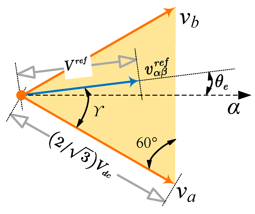
4.3. Overmodulation Design

In this section, the overmodulation strategy is designed. According to the last subsection, DFVL decreases with increasing speed. Thus, the over-modulation approach is necessary to take full advantage of higher bus utilization.
If the motor operates in the over-modulated region, there is an increasing harmonic current in the fundamental currents. Thus, considering the total harmonic distortion (THD), suppressing the zero-sequence current is unnecessary in the overmodulation operation region. Thus, if the amplitude of reference fundamental currents exceeds the maximum limit, the flux-weakening equation is:
g ω e , i d r e f , i q r e f = R s i q r e f + ω e L d i d r e f + ω e ψ f 2 + R s i d r e f ω e L q i q r e f 2 V d c 2 = 0
The corresponding optimization process is expressed as:
i d r e f k + 1 = i d r e f k η d g ω e , i d r e f , i q r e f d i d r e f
When this flux-weakening operation equation is utilized, the zero-sequence loop cannot be controlled, and the inner voltage sources cause ZSC. Then, the maximum modulation region will reach the size of the outer yellow hexagon in Figure 4a. Define the utilized fundamental voltage vectors as va and vb; the corresponding duty cycles are da and db, the sum of duty cycles is dall, and the overmodulation process is expressed as:
d a = d a / d a l l d b = d b / d a l l , i f   d a l l > 1

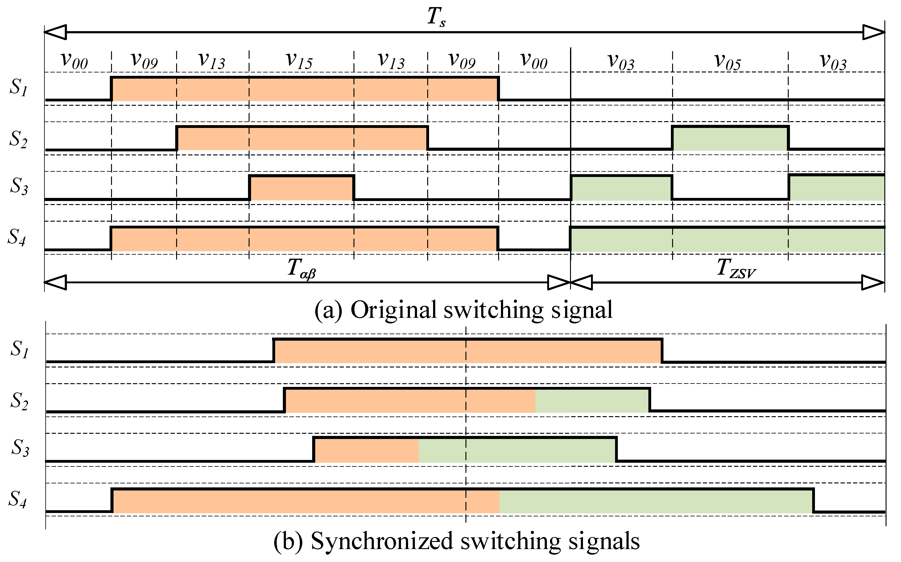
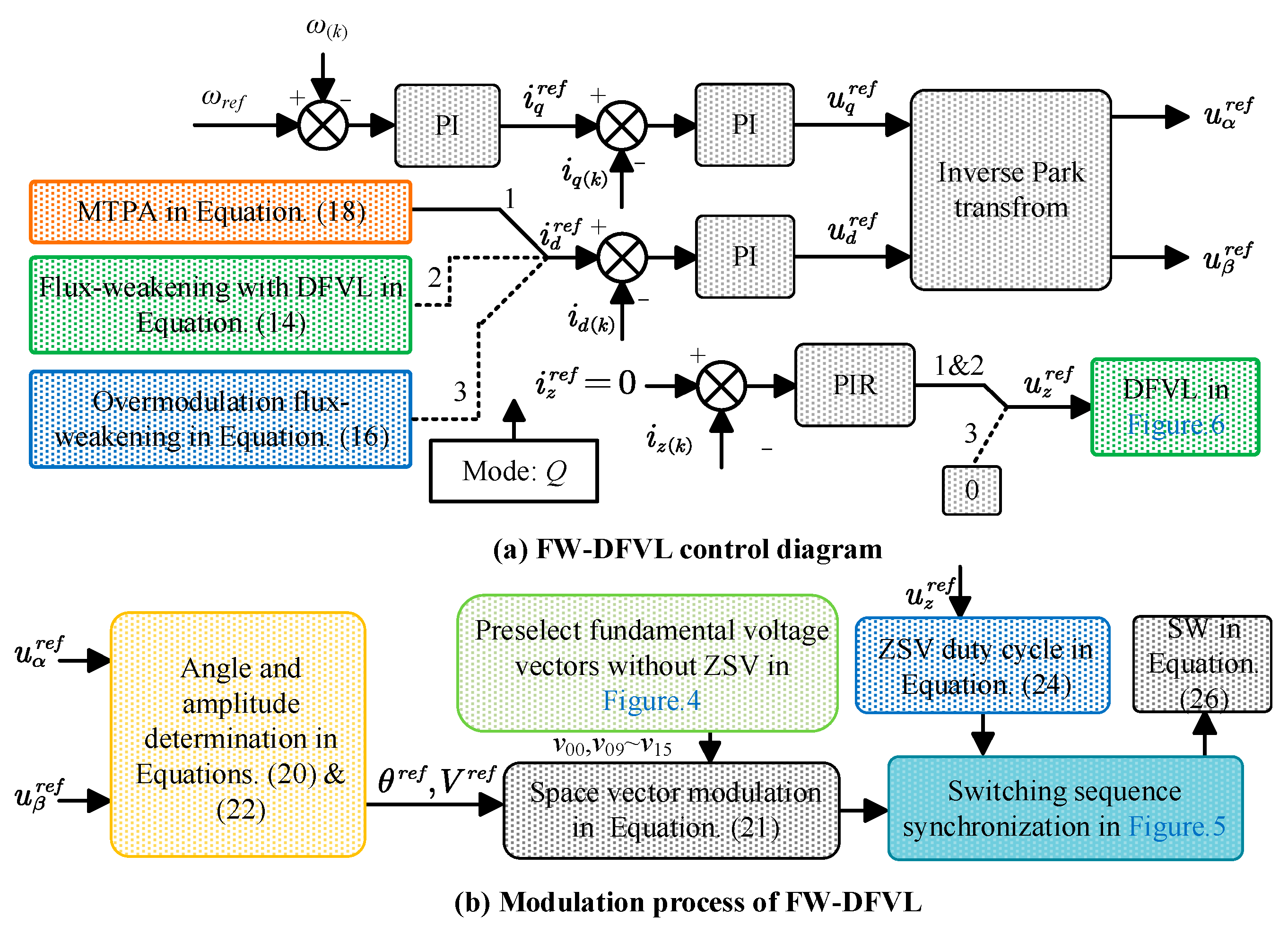
4.4. Total FW-DFVL Control Strategy

In this subsection, we will provide a block diagram of the FW-DFVL.
Figure 8 provides the total block diagram of the proposed FW-DFVL. Firstly, the outer speed loop gives the q-axis current reference, and the PI controller controls q- the axis current.
Secondly, the d-axis current reference is given by three different methods. The first method is the maximum torque per ampere (MTPA) [31], where the equation is expressed as:
i d | M T P A r e f = 1 + 4 ξ 2 i q r e f 2 1 2 ξ , ξ = L d L q ψ f
The second method is the proposed flux-weakening solution with DFVL, and the corresponding d-axis current reference has been expressed in Equation (14).
The third method is the proposed overmodulation method, and the corresponding d-axis current reference has been expressed in Equation (16).
We utilize the switching mode number Q to represent these three methods, and the expression of Q is shown in Equation (19).
Q = 1 , f ω e , i d r e f , i q r e f 0 2 , f ω e , i d r e f , i q r e f > 0 i d r e f 2 + i q r e f 2 < I m a x 2 3 , f ω e , i d r e f , i q r e f > 0 i d r e f 2 + i q r e f 2 I m a x
If Q equals one, the controller operates in the MTPA mode, where the reference d-axis current is determined from Equation (18). Then, if the amplitude of the reference voltage vectors in the fundamental subspace is higher than DFVL and the amplitude of reference currents in the d- and q-axes is lower than Imax, Q equals two, which means the controller operates in the flux-weakening region with DFVL. Moreover, suppose the amplitude of the reference voltage vectors in the fundamental subspace is higher than DFVL, and the amplitude of reference currents in the d- and q-axes is higher than Imax. In that case, Q equals three, which means the controller operates in the flux-weakening region with over-modulation.
Thirdly, the modulation method generates the output reference of current controllers. We determine the sector based on the angle of the fundamental voltage, where the angle of reference voltage vector θref is expressed as:
θ r e f = a t a n u β r e f / u α r e f
It needs to be mentioned that in the actual calculation process, atan2 function is utilized to ensure that the range of θref is proper.
Then, define the utilized non-zero fundamental voltage vectors as va and vb, the corresponding duty cycles are da and db, there is:
V r e f s i n 120 ° = d a V a s i n γ = d b V b s i n 60 ° γ
where the definition of γ is shown in Figure 9, Va and Vb are the amplitude of va and vb, respectively, and Vref is the amplitude of reference fundamental voltage, which is:
V r e f = u α r e f 2 + u β r e f 2
Moreover, Va and Vb can be expressed as:
V a = V b = 2 / 3 V d c
The duty cycle of ZSV is:
d Z S V = u z r e f / V d c / 3
ZSV1 is utilized as the zero-sequence voltage vector if the required zero-sequence voltage is positive. Otherwise, ZSV2 is applied.
The duty cycle of zero voltage vector v00 and v15 is shown in Equation (25):
d 0 = 1 d a d b d Z S V
The final output of the switching signal sequence can be expressed as:
S W = d a v a + d b v b + d Z S V v Z S V + d 0 v 00 / 2 + d 0 v 15 / 2
Moreover, it needs to be mentioned that if the switching mode number Q equals three, ZSC will not be suppressed, and u z r e f is replaced by zero. The yellow area in Figure 9 is the feasible region covered by va and vb.

4.5. Comparison with Conventional Flux-Weakening Strategy

This section compares the proposed FW-DFVL with the conventional flux-weakening control scheme in Figure 3.
The main difference between the two controllers is the fundamental voltage limit. In the conventional controller, the fundamental voltage limit is Vdc, which is unreachable due to the existence of ZSV. Moreover, the PI controller is utilized to generate the reference d-axis currents, which means the dynamic performance of the conventional controller is affected.
In contrast, the proposed FW-DFVL considers the existing ZSV, and the precise DFVL has been derived. Thus, the voltage limit of the proposed DFVL is different from the conventional controller. The voltage limit trajectories are shown in Figure 10a to further express this concept. The voltage limit trajectories without ZSV differ from those with 5% ZSV.
For instance, in an 800 rpm situation, the flux-weakening operation will not be applied in the conventional controller since the voltage limit trajectory, the blue line, is out of range. However, in the proposed FW-DFVL, the flux-weakening operation will be applied since the green line is inside the range. In other words, the voltage trajectories of the conventional flux-weakening controller are not achievable.
Finally, assume there is a 5% required ZSV in FW-DFVL. Then, the maximum torque versus speed capability will be divided into two parts. The first part is the operation region with ZSC suppression, as marked yellow in Figure 10b, where the zero-sequence current is well suppressed. The second part is the operation region without ZSC suppression, as observed in Figure 10b. The bus voltage is completely applied for the fundamental currents, and the zero-sequence current is generated by the high order back EMF.

5. Simulation Results

The simulation results are provided in this section to assess the proposed FW-DFVL. The conventional flux-weakening controller is also applied. The parameters of the utilized series-winding PMSM are shown in Table 1. The inductance parameters listed in the table were measured while the system was at rest, and they are considered constant since the proposed SW-PMSM operates in a linear stage where the phase currents have little effect on the inductance value. FFT (Fast Fourier Transform) is used to obtain the values of the magnet flux linkage and third magnet flux linkage during the no-load back EMF test. It should be noted that in a conventional star-connected PMSM, the utilization of the bus voltage is only 13.86 V. However, in the proposed series-winding PMSM, the bus voltage utilization is increased to 24 V. This significant increase in bus voltage utilization can expand the operational range of the drive system even further.
Firstly, the dynamic performance of the conventional flux-weakening controller and proposed FW-DFVL is shown in Figure 11. The load is set as 1 Nm, and the reference speed is changed from 800 rpm to 1200 rpm and then 1550 rpm. The large speed error and current ripples in the dq subspace are two main disadvantages of the conventional flux-weakening controller.
In contrast, the proposed FW-DFVL can obtain better dynamic performance, as shown in Figure 12. The series-winding PM machines can reach reference speed and rapid dynamic performance.
To further reveal the problems with the conventional algorithm, the steady-state system properties are shown in Figure 13, Figure 14 and Figure 15. In Figure 13, the series-winding PM machines operate at 800 rpm, where the ZSC is well suppressed, and the fundamental currents are well generated.
In Figure 14, the series-winding PM machines should operate in the flux-weakening condition. While since the utilized voltage limit Vdc cannot be reached, the system cannot work correctly in the flux-weakening operation region. Both the fundamental currents and the phase currents are distorted. Similar performance is also observed in Figure 15.
On the contrary, in the proposed FW-DFVL, the voltage vectors are always feasible because of the DFVL, and the steady-state performance is shown in Figure 16, Figure 17 and Figure 18. In Figure 16, the proposed FW-DFVL also operates in MTPA condition, where the performance is similar to the conventional controller. However, the performance in the flux-weakening operation region of the proposed FW-DFVL is much better. In Figure 17, the proposed FW-DFVL can realize precise fundamental current generation and ZSC suppression. Furthermore, in Figure 18, the proposed FW-DFVL operates in the overmodulation region where ZSC is not controlled. In this operation region, FW-DFVL will give up control of ZSC in exchange for higher bus voltage utilization. Thus, the precise fundamental current generation and larger ZSC are observed.
In summary, the conventional flux-weakening controller cannot work properly in the series-winding PMSM. The reason is that the ideal fundamental voltage limit is infeasible. Thus, the proposed FW-DFVL, which utilizes the DFVL, and gradient descent method, can obtain better steady-state performance and dynamic performance.

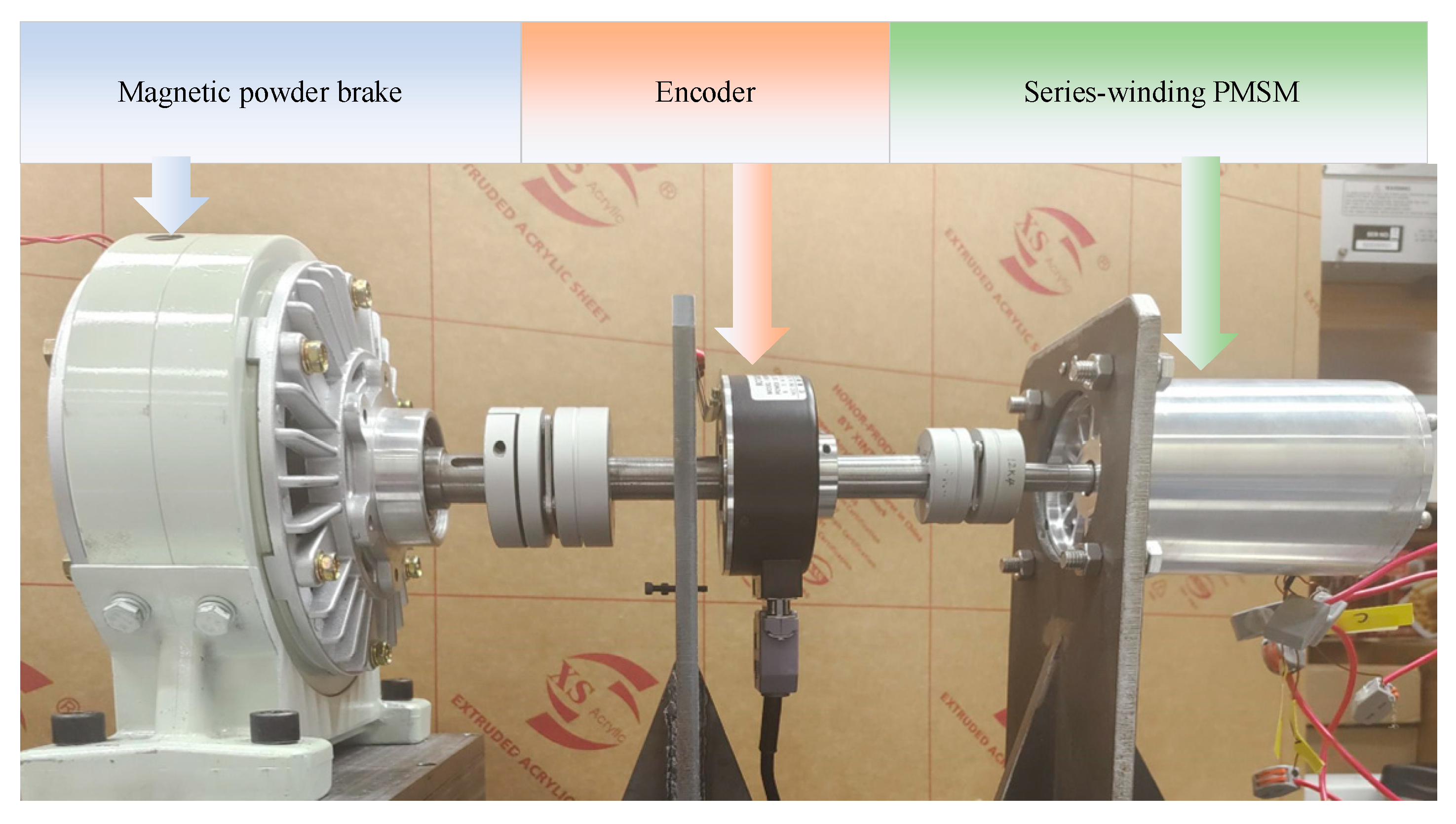
6. Experimental Results

In this section, the performance of the proposed FW-DFVL will be further discussed with experimental results. The platform is shown in Figure 19, where the parameter of the series-winding PMSM has been demonstrated in Table 1, and the deadtime of the inverter is two us. The DC power supplies the bus voltage, and DS1202 performs the control actions. The 200 W magnetic powder brake is taken as the load.

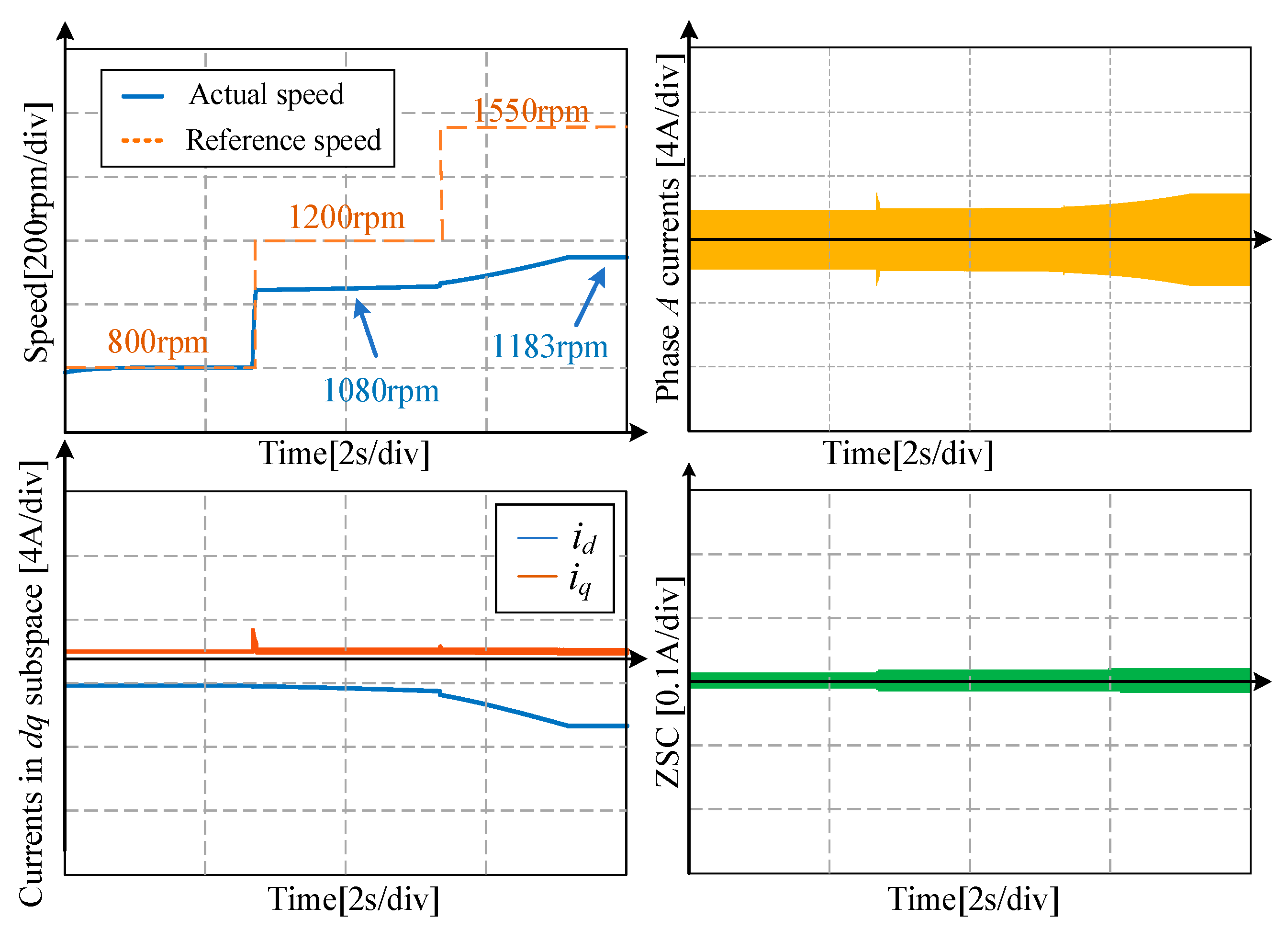
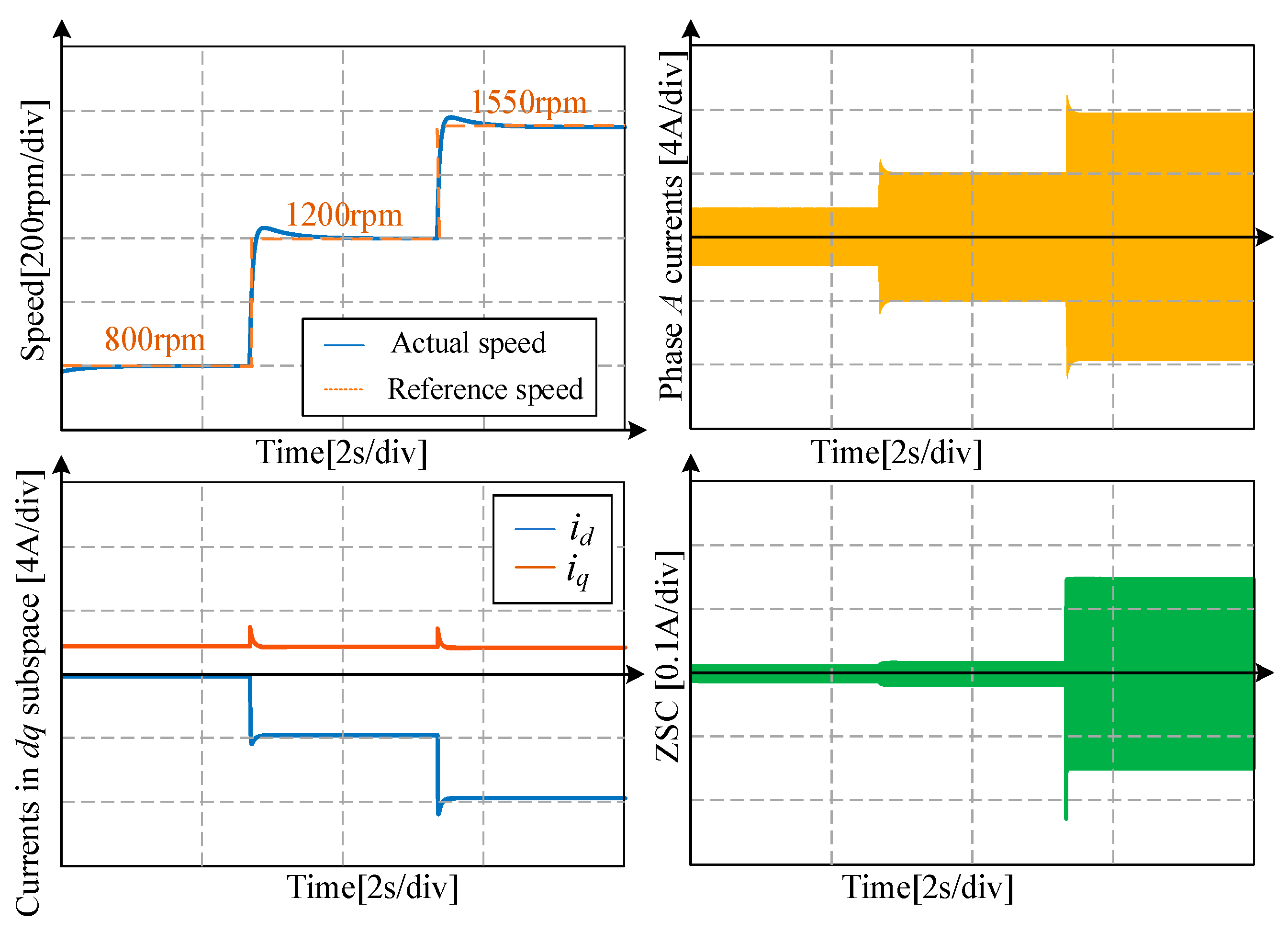
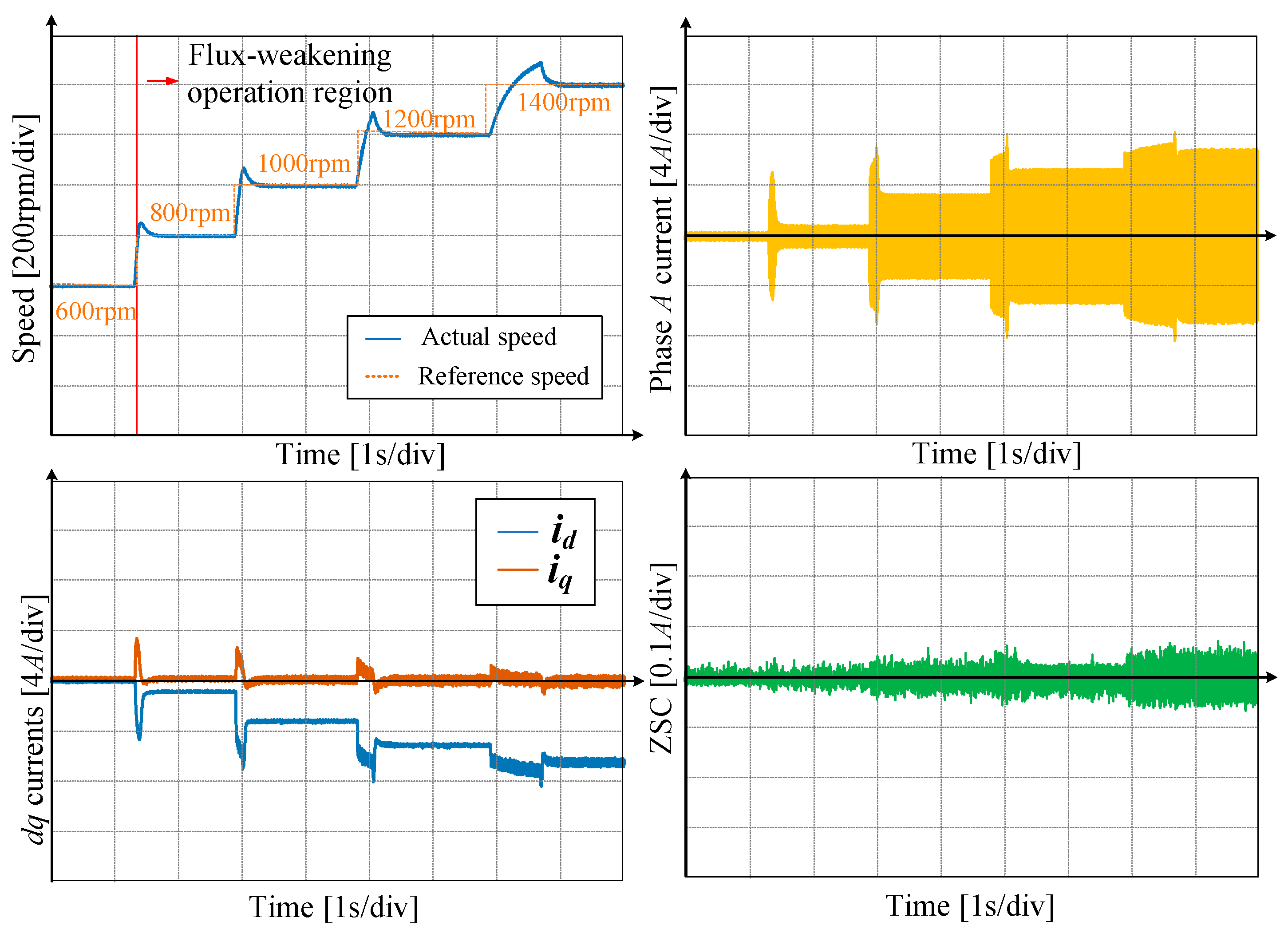
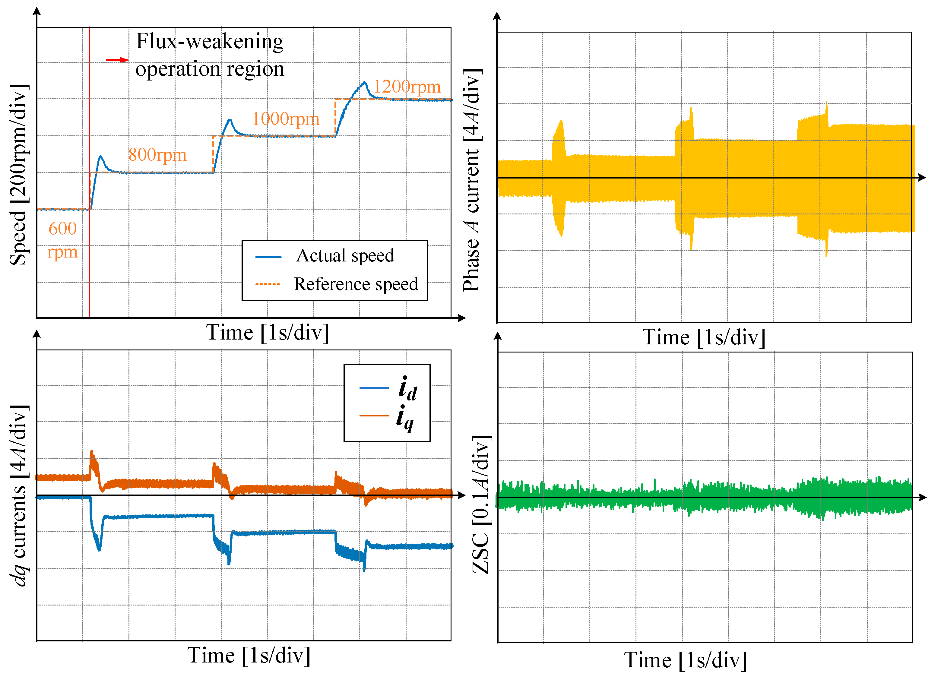
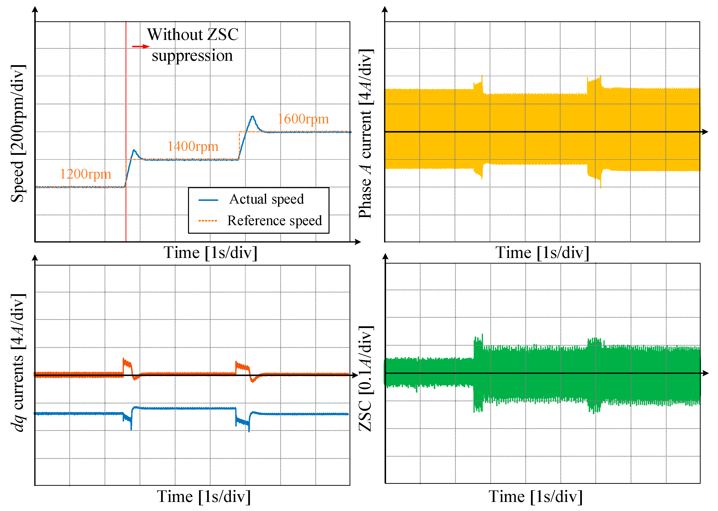
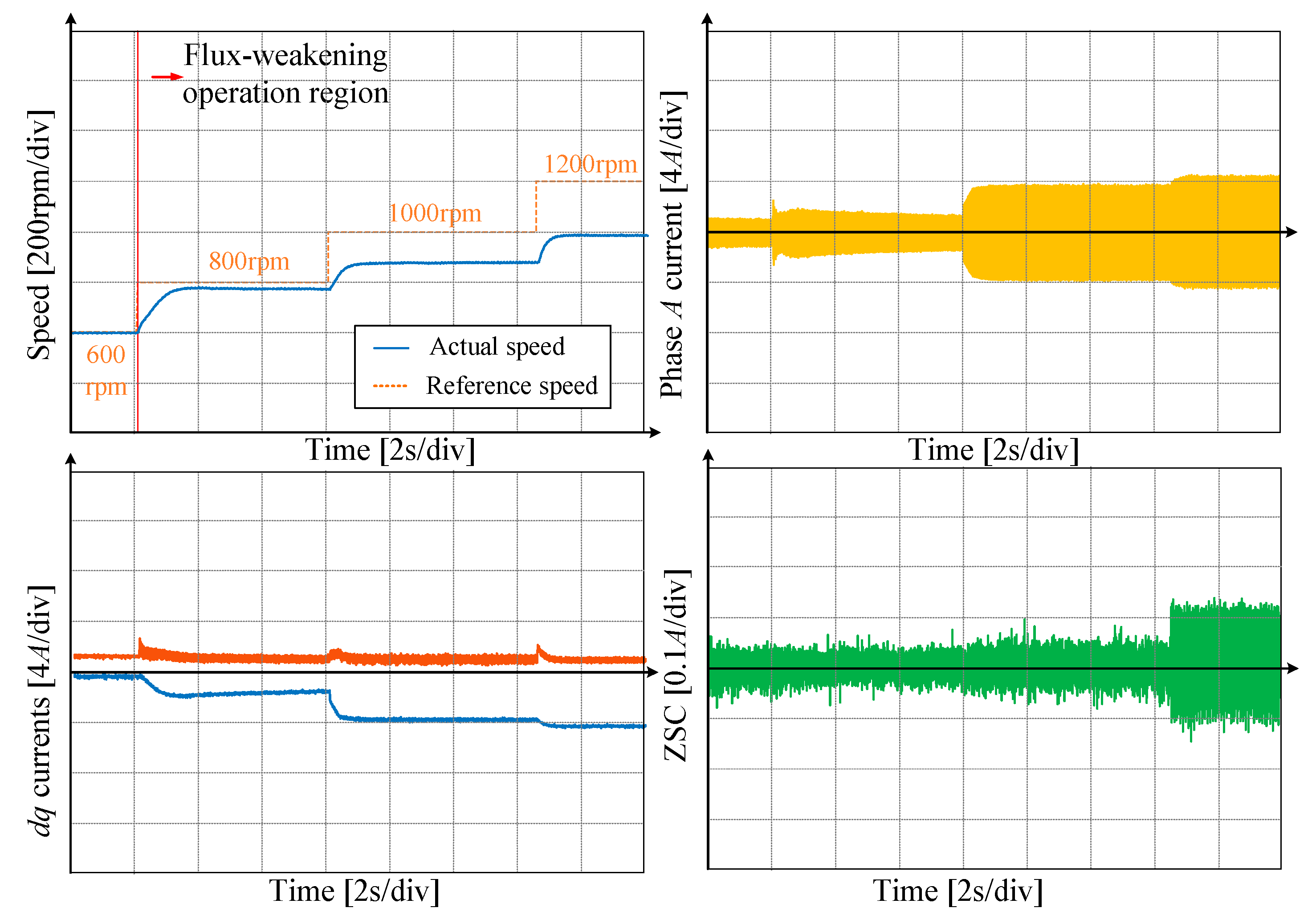
6.1. Dynamic Performance

In this subsection, the dynamic experiment is designed to verify the dynamic performance of this strategy. Moreover, the conventional flux-weakening control scheme is utilized to express the advantages of the proposed controller.
During the experimental section, the parameters of the speed PI controller are fixed as Kp = 0.03 and Ki = 0.2, and the control frequency is fixed as 20 kHz. In Figure 20, the dynamic performance is tested under a no-load condition, where the reference speed is set from 600 rpm to 1400 rpm. ZSC is all suppressed in Figure 20, and the maximum speed is about 1400 rpm. Moreover, it needs to be mentioned that under 1400 rpm, DFVL is about 36 V because of the increasing inner voltage sources in the zero-sequence loop. Thus, the maximum speed obtained with ZSC suppression is lower than the simulation results.
Moreover, another acceleration experiment is provided in Figure 21, where the load is set as 0.6 Nm, and the reference speed is set from 600 rpm to 1200 rpm. The performance trend is like the no-load condition situation. Moreover, the maximum speed is lower than the no-load condition because the torque generation also consumes bus voltage, and PMSM cannot reach 1400 rpm.
Then, the maximum speed of the proposed FW-DFVL will further increase without ZSC suppression. Figure 22 provides the acceleration performance of FW-DFVL from 1200 rpm to 1600 rpm. It can be observed that there is a sudden increase in ZSC from the 1400 rpm situation. The mechanism is that ZSC current is not further suppressed, and the higher bus voltage utilization is obtained. Finally, we will assess the performance of the conventional flux-weakening controller in Figure 23, where the load is 0.6 Nm, and the reference speed is set from 600 rpm to 1200 rpm. The performance is similar to the simulation results, where the speed cannot reach the reference speed because of the inaccurate fundamental voltage limit. Thus, the conventional flux-weakening controller with the improper fixed fundamental voltage limit is unsuitable for series-winding PMSM.
Moreover, the computation burden of two controllers is compared in the utilized space. The execution time of the conventional flux-weakening controller is 28.2 μs, and the execution time of FW-DFVL is 32.4 μs. The increase in the execution time is mainly caused by the gradient descent method.

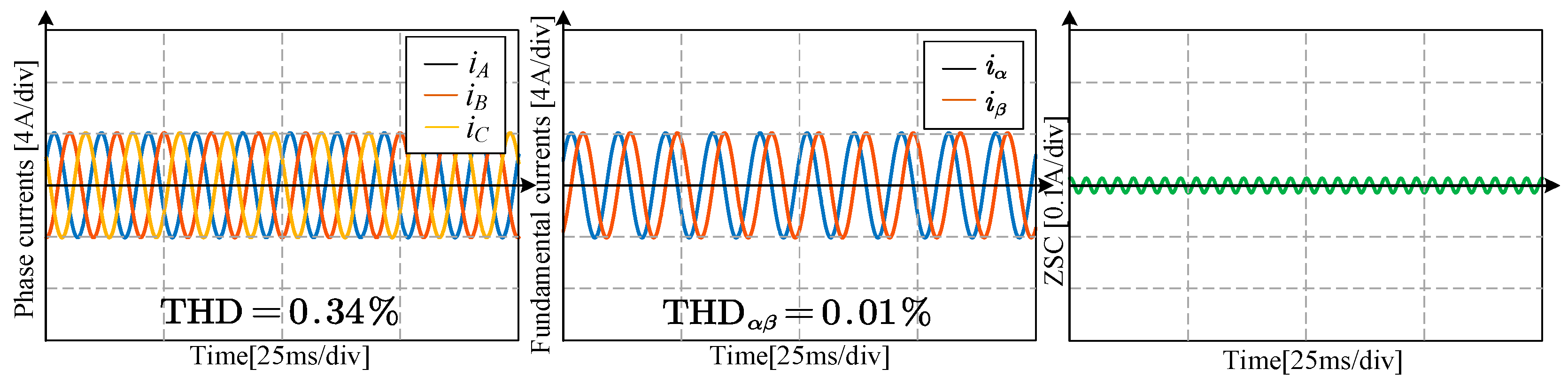
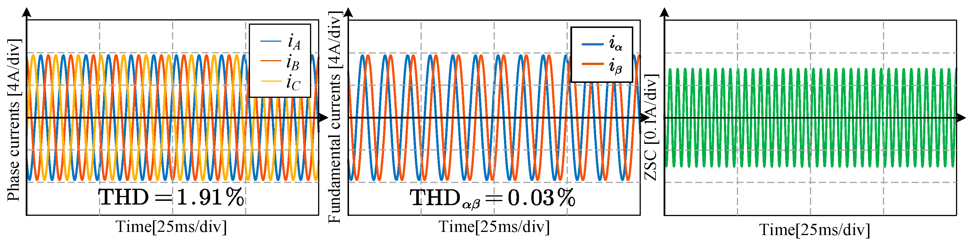
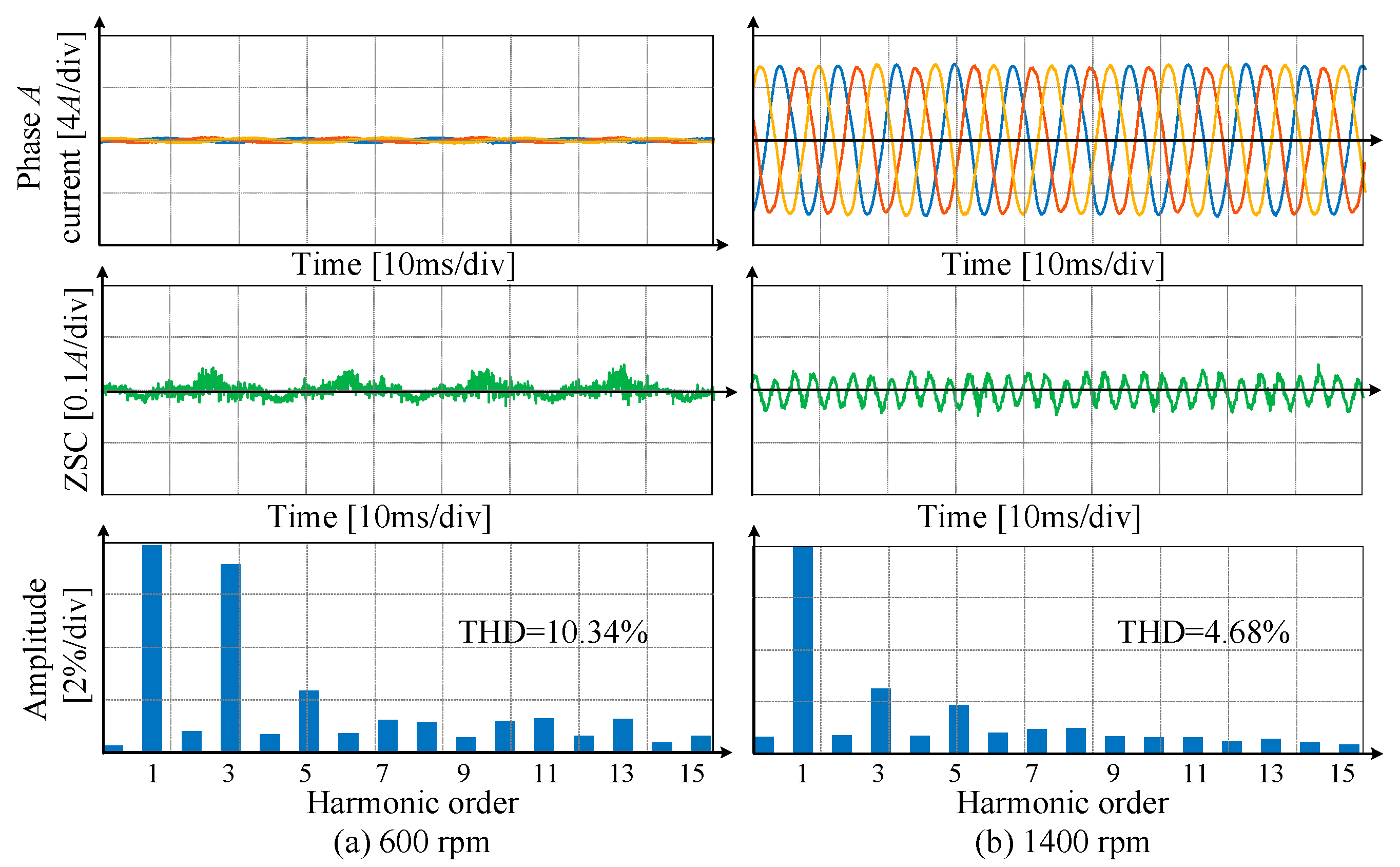
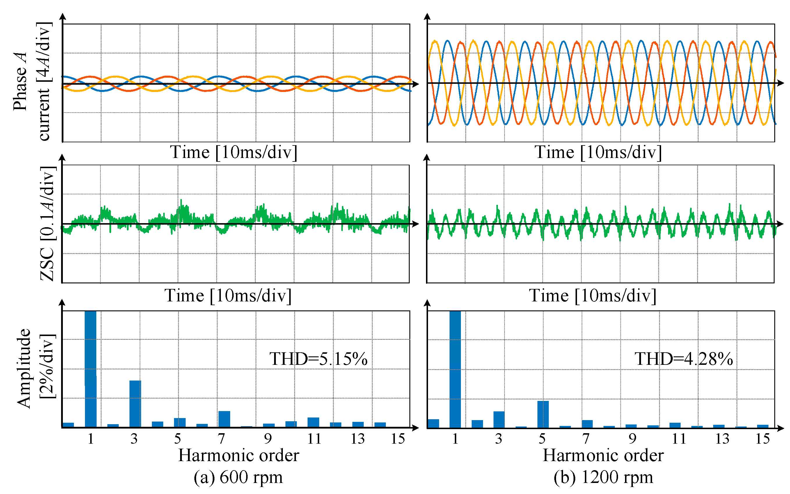
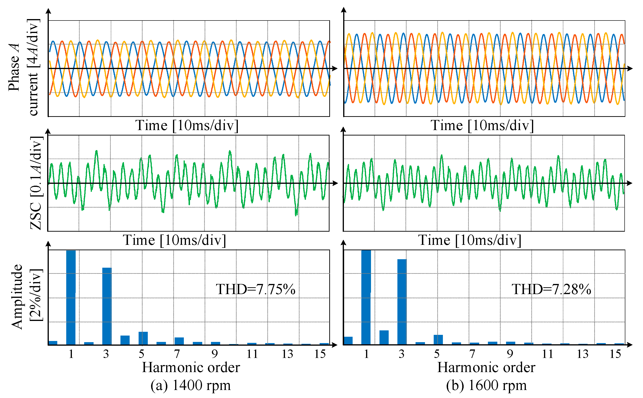
6.2. Steady-State Performance

Four operation conditions are tested in this section, and the phase currents, ZSC, and the Fast Fourier Transform (FFT) results are provided. Figure 24 provides the steady-state performance of the proposed FW-DFVL under no-load conditions. Figure 24 includes two different operation points. In Figure 24a, the operation point is located in the MTPA operation region. Then, the proposed FW-DFVL does not enter the flux-weakening operation region, and ZSC can be well suppressed. In Figure 24b, FW-DFVL operates in the flux-weakening region where the phase currents are mainly applied to offset the back electromotive force components, allowing the series-winding PMSM to operate over the rated speed. Moreover, the total harmonic distortion (THD) is still more significant at 600 rpm than at 1400 rpm. The phase current amplitude is smaller at 600 rpm; therefore, ZSC will cause more THD.
Figure 25 also includes the operation point in the MTPA region and the flux-weakening region. In Figure 25a, the system operates in the MTPA region, and in Figure 25b, the system operates in the flux-weakening region. The performance trend is similar to the no-load condition, where ZSC is well suppressed in both the normal and the flux-weakening operation conditions.
Figure 26 includes the overmodulation operation points. In Figure 26, ZSC is not suppressed, and THD will increase. However, considering the increasing speed, the rising THD is acceptable.

7. Conclusions

In this paper, a novel FW-DFVL scheme is designed for the traction system with a series-winding connection, which enables the series-winding motor with limited bus voltage to run above the rated speed.
The dynamic fundamental voltage limit is crucial in the flux-weakening controller design for series-winding PMSM or multiphase PMSM, which have multiple current subspaces. The fixed fundamental voltage limit is far from the actual fundamental voltage limit and cannot ensure the feasible voltage vectors in the fundamental subspace. This problem is solved in this paper with DFVL, and the contribution of this paper can be divided into three parts:
(1) The concept of dynamic fundamental voltage limit is proposed in this paper. This DFVL can ensure the feasible voltage vectors in both the fundamental subspace and the zero-sequence loop.
(2) The gradient descent method is applied to solve the optimal flux-weakening current online. This feedforward solution will improve dynamic performance.
(3) The overmodulation solution for series-winding PMSM is provided. The essence of this overmodulation solution is to actively release the control of ZSC and obtain higher bus voltage utilization.

Author Contributions

Conceptualization, S.L. and C.L.; Methodology, S.L.; Software, Z.S. and B.Z.; Validation, C.L.; Writing—original draft, S.L.; Writing—review and editing, S.L., B.Z. and C.L.; Supervision, C.L.; project administration, C.L.; funding acquisition, C.L. All authors have read and agreed to the published version of the manuscript.

Funding

This work was supported by a Collaborative Research Fund (CRF Project No. C1052-21GF) from the Research Grants Council, Hong Kong SAR; in part by RGC Research Fellow Scheme (RGC Ref. No.: RFS2223-1S05) from Research Grants Council, Hong Kong SAR; and in part by the grants (Project No. TDG6000784 and ARG9667251) from the Teaching Development Grant and Applied Research Grant, City University of Hong Kong, Hong Kong SAR.

Data Availability Statement

Not applicable.

Conflicts of Interest

The authors declare no conflict of interest.

References

  1. Bai, J.; Liu, J.; Zheng, P.; Tong, C. Design and analysis of a magnetic-field modulated brushless double-rotor machine—Part I: Pole pair combination of stator, pm rotor and magnetic blocks. IEEE Trans. Ind. Electron. 2018, 66, 2540–2549. [Google Scholar] [CrossRef]
  2. Liu, S.; Liu, C.; Huang, Y.; Zhao, H. Model Predictive Two-Target Current Control for OW-PMSM. IEEE Trans. Power Electron. 2020, 36, 3224–3235. [Google Scholar] [CrossRef]
  3. Bindu, R.; Namboothiripad, M.K. Tuning of PID controller for DC servo motor using genetic algorithm. Int. J. Emerg. Technol. Adv. Eng. 2012, 2, 310–314. [Google Scholar]
  4. Niu, G.; Liu, S. Demagnetization monitoring and life extending control for permanent magnet-driven traction systems. Mech. Syst. Signal Process. 2018, 103, 264–279. [Google Scholar] [CrossRef]
  5. Yang, J.; Jiang, D.; Sun, H.; Li, A.; Liu, Z. Series-Winding Topology Converter for Active Magnetic Bearing Drive. IEEE Trans. Ind. Electron. 2020, 68, 11772–11782. [Google Scholar] [CrossRef]
  6. Dong, Z.; Liu, C.; Song, Z.; Liu, S. Suppression of Dual-Harmonic Components for Five-Phase Series-Winding PMSM. IEEE Trans. Transp. Electrif. 2021, 8, 121–134. [Google Scholar] [CrossRef]
  7. Li, A.; Jiang, D.; Liu, Z.; Sun, X. Generalized PWM Method for Series-End Winding Motor Drive. IEEE Trans. Power Electron. 2020, 36, 4452–4462. [Google Scholar] [CrossRef]
  8. Liu, S.; Liu, C. Flux Weakening Control for Dual Three-Phase PMSM. In Proceedings of the 2018 Asia-Pacific Magnetic Recording Conference (APMRC), Shanghai, China, 15–17 November 2018; pp. 1–2. [Google Scholar] [CrossRef]
  9. Fan, W.; Zhu, X.; Quan, L.; Wu, W.; Xu, L.; Liu, Y. Flux-Weakening Capability Enhancement Design and Optimization of a Controllable Leakage Flux Multilayer Barrier PM Motor. IEEE Trans. Ind. Electron. 2020, 68, 7814–7825. [Google Scholar] [CrossRef]
  10. Fang, S.; Liu, Q.; Lin, H.; Ho, S.L. A Novel Flux Weakening Control Strategy for Permanent Magnet Actuator of Vacuum Circuit Breaker. IEEE Trans. Ind. Electron. 2015, 63, 2275–2283. [Google Scholar] [CrossRef]
  11. Jahns, T.M. Flux-Weakening Regime Operation of an Interior Permanent-Magnet Synchronous Motor Drive. IEEE Trans. Ind. Appl. 1987, IA-23, 681–689. [Google Scholar] [CrossRef]
  12. Tapia, J.; Leonardi, F.; Lipo, T. Consequent-pole permanent-magnet machine with extended field-weakening capability. IEEE Trans. Ind. Appl. 2003, 39, 1704–1709. [Google Scholar] [CrossRef] [Green Version]
  13. Morimoto, S.; Sanada, M.; Takeda, Y. Effects and Compensation of Magnetic Saturation in Flux-Weakening Controlled Permanent Magnet Synchronous Motor Drives. IEEE Trans. Ind. Appl. 1994, 30, 1632. [Google Scholar] [CrossRef]
  14. Cheng, B.; Tesch, T.R. Torque Feedforward Control Technique for Permanent Magnet Synchronous Motors. In Proceedings of the IECON 2007—33rd Annual Conference of the IEEE Industrial Electronics Society, Taipei, Taiwan, 5–8 November 2007; pp. 1055–1060. [Google Scholar] [CrossRef]
  15. Wang, C.; Zhu, Z.Q. Fuzzy Logic Speed Control of Permanent Magnet Synchronous Machine and Feedback Voltage Ripple Reduction in Flux-Weakening Operation Region. IEEE Trans. Ind. Appl. 2020, 56, 1505–1517. [Google Scholar] [CrossRef]
  16. Lu, D.; Kar, N.C. A Review of Flux-Weakening Control in Permanent Magnet Synchronous Machines. In Proceedings of the 2010 IEEE Vehicle Power and Propulsion Conference, Lille, France, 1–3 September 2010. [Google Scholar]
  17. Kwon, Y.-C.; Kim, S.; Sul, S.-K. Voltage Feedback Current Control Scheme for Improved Transient Performance of Permanent Magnet Synchronous Machine Drives. IEEE Trans. Ind. Electron. 2011, 59, 3373–3382. [Google Scholar] [CrossRef]
  18. Liu, S.; Liu, C. Virtual-Vector-Based Robust Predictive Current Control for Dual Three-Phase PMSM. IEEE Trans. Ind. Electron. 2020, 68, 2048–2058. [Google Scholar] [CrossRef]
  19. Preindl, M.; Bolognani, S. Model Predictive Direct Torque Control With Finite Control Set for PMSM Drive Systems, Part 2: Field Weakening Operation. IEEE Trans. Ind. Inform. 2012, 9, 648–657. [Google Scholar] [CrossRef]
  20. Bianchi, N.; Carlet, P.G.; Cinti, L.; Ortombina, L. A Review about Flux-Weakening Operating Limits and Control Techniques for Synchronous Motor Drives. Energies 2022, 15, 1930. [Google Scholar] [CrossRef]
  21. Yang, J.; Jiang, D.; Sun, H.; Ding, J.; Li, A.; Liu, Z. A Series-Winding Topology Converter With Capability of Fault-Tolerant Operation for Active Magnetic Bearing Drive. IEEE Trans. Ind. Electron. 2021, 69, 6678–6687. [Google Scholar] [CrossRef]
  22. Manzolini, V.; Da Ru, D.; Bolognani, S. An Effective Flux Weakening Control of a SyRM Drive Including MTPV Operation. IEEE Trans. Ind. Appl. 2018, 55, 2700–2709. [Google Scholar] [CrossRef]
  23. Li, A.; Jiang, D.; Sun, X.; Liu, Z. Method of Expanding Operating Range for Three-phase Series-end Winding Motor Drive. In Proceedings of the 2020 IEEE Energy Conversion Congress and Exposition (ECCE), Detroit, MI, USA, 11–15 October 2020; pp. 2020–2025. [Google Scholar] [CrossRef]
  24. Dong, Z.; Liu, C.; Liu, S.; Song, Z. Deadbeat Predictive Current Control for Series-Winding PMSM Drive with Half-Bridge Power Module-Based Inverter. Energies 2021, 14, 4620. [Google Scholar] [CrossRef]
  25. Liu, S.; Liu, C. Direct Harmonic Current Control Scheme for Dual Three-Phase PMSM Drive System. IEEE Trans. Power Electron. 2021, 36, 11647–11657. [Google Scholar] [CrossRef]
  26. Song, Z.; Liu, C.; Liu, S.; Wang, W. Active harmonic suppression of low-reactance multi-phase slotless permanent magnet synchronous machines. IEEE J. Emerg. Sel. Top. Power Electron. 2021, 10, 1777–1787. [Google Scholar] [CrossRef]
  27. Ren, Z.; Ji, J.; Tang, H.; Tao, T.; Huang, L.; Zhao, W. Model Predictive Torque Control for a Dual Three-phase PMSM Using Modified Dual Virtual Vector Modulation Method. Chin. J. Electr. Eng. 2022, 8, 91–103. [Google Scholar] [CrossRef]
  28. Liu, S.; Liu, C.; Song, Z.; Dong, Z.; Huang, Y. Candidate Modulation Patterns Solution for Five-Phase PMSM Drive System. IEEE Trans. Transp. Electrif. 2021, 8, 1194–1208. [Google Scholar] [CrossRef]
  29. Liu, S.; Liu, C.; Huang, Y.; Xiao, Y. Direct Modulation Pattern Control for Dual Three-Phase PMSM Drive System. IEEE Trans. Ind. Electron. 2021, 69, 110–120. [Google Scholar] [CrossRef]
  30. Mohamed, Y.-R.; Lee, T. Adaptive Self-Tuning MTPA Vector Controller for IPMSM Drive System. IEEE Trans. Energy Convers. 2006, 21, 636–644. [Google Scholar] [CrossRef]
  31. Liu, S.; Song, Z.; Dong, Z.; Liu, Y.; Liu, C. Generic Carrier-Based PWM Solution for Series-End Winding PMSM Traction System With Adaptative Overmodulation Scheme. IEEE Trans. Transp. Electrif. 2022, 9, 712–726. [Google Scholar] [CrossRef]
  32. Liu, S.; Liu, C.; Zhao, H.; Liu, Y.; Dong, Z. Improved Flux Weakening Control Strategy for Five-Phase PMSM Considering Harmonic Voltage Vectors. IEEE Trans. Power Electron. 2022, 37, 10967–10980. [Google Scholar] [CrossRef]
  33. Song, Z.; Liu, C.; Dong, Z.; Huang, R. Improved Multi-Stage Decoupling Space Vector Modulation for Asymmetrical Multi-Phase PMSM With Series Winding Connection. IEEE Trans. Power Electron. 2022, 37, 10951–10966. [Google Scholar] [CrossRef]
  34. Zhan, H.; Zhu, Z.-Q.; Odavic, M. Analysis and Suppression of Zero Sequence Circulating Current in Open Winding PMSM Drives With Common DC Bus. IEEE Trans. Ind. Appl. 2017, 53, 3609–3620. [Google Scholar] [CrossRef]
  35. Taha, W.; Emadi, A. Online Non-Parametric Auto-Tuning of Flux Weakening Controller for IPMSM Drives Using Modified Relay Feedback Test. In Proceedings of the 2021 IEEE Transportation Electrification Conference & Expo (ITEC), Chicago, IL, USA, 21–25 June 2021. [Google Scholar]
  36. Bolognani, S.; Calligaro, S.; Petrella, R. Optimal Voltage Feed-Back Flux-Weakening Control of IPMSM. In Proceedings of the IECON 2011—37th Annual Conference of the IEEE Industrial Electronics Society, Melbourne, Australia, 7–10 November 2011. [Google Scholar]
Figure 1. Drive system of series-winding PMSM.
Wevj 14 00107 g001
Figure 2. Voltage vectors of series-winding PMSM.
Wevj 14 00107 g002
Figure 3. The control diagram of the conventional flux-weakening control strategy.
Wevj 14 00107 g003
Figure 4. Preselected voltage vectors.
Wevj 14 00107 g004
Figure 5. Switching signal centralization.
Wevj 14 00107 g005
Figure 6. The process of dynamic fundamental voltage limit.
Wevj 14 00107 g006
Figure 7. Experimental results of DFVL from 400 rpm to 1600 rpm.
Wevj 14 00107 g007
Figure 8. Control diagram of FW-DFVL.
Wevj 14 00107 g008
Figure 9. Definition of modulation parameters.
Wevj 14 00107 g009
Figure 10. Operation region comparison.
Wevj 14 00107 g010
Figure 11. Simulation dynamic performance of the conventional flux-weakening controller.
Wevj 14 00107 g011
Figure 12. Simulation dynamic performance of proposed FW-DFVL.
Wevj 14 00107 g012
Figure 13. Simulation steady-performance of the conventional controller under 800 rpm reference.
Wevj 14 00107 g013
Figure 14. Simulation steady-performance of the conventional controller under 1200 rpm reference.
Wevj 14 00107 g014
Figure 15. Simulation steady-performance of the conventional controller under 1550 rpm reference.
Wevj 14 00107 g015
Figure 16. Simulation steady-performance of proposed FW-DFVL under 800 rpm reference.
Wevj 14 00107 g016
Figure 17. Simulation steady-performance of proposed FW-DFVL under 1200 rpm reference.
Wevj 14 00107 g017
Figure 18. Simulation steady-performance of proposed FW-DFVL under 1550 rpm reference.
Wevj 14 00107 g018
Figure 19. Experimental platform.
Wevj 14 00107 g019
Figure 20. Dynamic performance of FW-DFVL under no load.
Wevj 14 00107 g020
Figure 21. Dynamic performance of FW-DFVL under 0.6 Nm.
Wevj 14 00107 g021
Figure 22. Overmodulation dynamic performance of FW-DFVL under 0.6 Nm.
Wevj 14 00107 g022
Figure 23. Dynamic performance of conventional controller under 0.6 Nm.
Wevj 14 00107 g023
Figure 24. Steady-state performance of FW-DFVL under no load (a) 600 rpm situation (b) 1400 rpm situation.
Wevj 14 00107 g024
Figure 25. Steady-state performance of FW-DFVL under 0.6 Nm (a) 600 rpm situation (b) 1200 rpm situation.
Wevj 14 00107 g025
Figure 26. Overmodulation steady-state performance of FW-DFVL under 0.6 Nm (a) 1400 rpm situation (b) 1600 rpm situation.
Wevj 14 00107 g026
Table 1. Parameter of series-winding PMSM.
ParameterDescriptionValue
npNumber of pole pairs5
Rs (Ω)Stator resistance1.4
Ld (mH)Inductance in d-axis3.7
Lq (mH)Inductance in q-axis5.0
Lz (mH)Inductance in the z-axis8.4
ψf (Wb)Magnet flux linkage0.04
ψf3 (mWb)Third-order magnet flux linkage12
J (kg.m2)Rotational inertia0.00005
VDC (V)DC bus voltage24
Speed (r/min)Rated speed800
Torque (N.m)Rated torque4.5
F (kHz)Sampling frequency20
Disclaimer/Publisher’s Note: The statements, opinions and data contained in all publications are solely those of the individual author(s) and contributor(s) and not of MDPI and/or the editor(s). MDPI and/or the editor(s) disclaim responsibility for any injury to people or property resulting from any ideas, methods, instructions or products referred to in the content.

