1. Introduction
Diamond-abrasive tools with metallic binders are in wide use in various industries for processing metal and non-metal materials. The tool performance depends on many factors, including the strength and cutting ability of diamond grains. Additionally, the physical and mechanical properties, as well as the tribological properties of the metallic binder, are impotent factors to consider. The adhesive interaction between the metal and diamond components at their interface also plays a crucial role [
1,
2]. Moreover, special requirements are imposed on the binder material: on the one hand, it must ensure strong retention of diamond grains during cutting, and on the other hand, the binder must gradually bare diamond crystals under the action of the material being processed, exposing “new” abrasive grains to the cutting surface. Premature chipping of diamonds is most often caused by insufficient strength, microhardness or plasticity of the binder in the working area during heating and intense wear under the action of the abrasive sludge flow [
3,
4]. Metallic binders of varying hardness and wear resistance (copper, iron, nickel, cobalt and their alloys) are used depending on the type of material being processed. Cobalt-based binders have high strength properties and wear resistance [
3,
5,
6]. Despite their high cost, there is a need for the development of new, more economical options for metallic binders that exhibit high mechanical strength and heat resistance, as well as improved tribotechnical characteristics. These features can lead to increased durability of the diamond-abrasive tools.
Low-cost powders of copper–tin or iron materials are attractive as bases for new binders due to the optimal combination of performance properties, manufacturability and availability of metals [
7,
8]. Carbonyl iron-based binders can already replace cobalt ones [
8]. To increase the wear resistance and strength of alloys, both hardening with their dispersed particles [
9,
10] and dispersion strengthening with intermetallic compound formation through supersaturated solid solution decomposition [
11] are used. To increase the adhesion interaction with diamond, alloying with active metals (Ti, Cr, Ni, Fe, W and Co) is applied, which provides a good wettability of diamond and chemical interaction on the contact layer with the formation of a metal carbide coatings [
12,
13]. However, metallic binders, such as Co, Fe and Ni that possess a high affinity with carbon, accelerate the graphitization process [
14,
15]. The high catalytic activity of iron to diamond leads to the graphitization with the formation of a wide transition layer with a granular structure [
15], which reduces the adhesion strength of the layer to the binder, and requires the creation of a barrier layer at the contact.
Titanium has a relatively low catalytic activity towards diamond [
16]. Titanium alloying of copper or iron alloys improves their wear-resistant and corrosion properties due to solid-solution hardening [
17]. The titanium content in copper and copper–tin compositions varies from 0.7 to 15% [
13,
18]. Its higher content improves wetting, but at >10 wt.% of Ti the formation of a dense layer of TiC [
19] reduces the bond strength, and at 17.5 wt.% of Ti the created stresses can destroy the diamond grain [
13]. Iron-based binders use metalized diamonds coated with titanium [
20] or TiC [
12]. The TiC layer on the diamond grain allows for avoiding direct contact with Fe and prevents graphitization of the diamond. However, the use of coated diamonds significantly increases the cost of the tool, so obtaining a layer of TiC on the diamond without metallization is of interest. It was reported in [
21,
22] that the effect of spontaneous cladding can be realized for a nanomodified metallic binder. Technological techniques involve the direct introduction of titanium into the composition of the powder mixture by mixing [
23] or melt impregnation into the porous compacts [
18]. It should be noted that, in the first case, it is not possible to obtain a clad layer on the diamond even with the increase in the contact time due to the probable interaction with the binder components. High sintering temperatures, especially for the iron-based binder, can lead to the graphitization of diamond, and active titanium is intensely oxidized before it reacts with carbon [
24]. At the same time, the metallic binders with a high titanium content of ~30–50 wt.% Ni-Ti [
25] and Ti-Fe [
26] are suitable as a new type of binder for high-performance diamond-abrasive tools and have a high potential as a bonding material for the manufacturing of grinding tools via the laser powder bed fusion technique by creating a bulk ultra-thin microstructure.
A promising way to obtain nanostructured metallic binder powders is mechanical alloying (MA). A preliminary mechanical activation of the binder material in high-energy ball mills can lead to a significant decrease in the diffusion activation energy due to the formation of defects, which reduces the temperature and sintering time. It allows for avoiding high-temperature diamond damage. It is especially important for iron-based diamond metal matrix composites [
27]. The microstructure of the matrix becomes more homogeneous, and the density, hardness and strength of the matrix are significantly improved, which results in increasing the bond strength [
28] and service lifetime of diamond tools [
29]. However, the hardness of the powders increases with prolonged mechanical treatment, and the sintering properties of the powders become less expressed. The structure of the powder mixtures depends on the MA duration and affects their technological properties (compressibility, sintering temperature), diffusion processes during sintering and final materials properties [
30,
31,
32,
33]. The powder structure of mixtures Cu-2.5%Ti, Cu-10%TiH
2 [
31], iron-based Fe-Co-Ni-3%TiH
2 [
32] and Cu-20Sn [
33] via high-energy ball milling evolves from a layered to a solid solution. An increase in the strength and wear resistance of MA metallic binders is due to the supersaturated solid solutions formation followed by dispersion strengthening with intermetallic compounds during sintering [
32,
33]. The formation of a local TiC carbide layer on diamond with a thickness of no more than 50 nm for the iron binder is also possible.
This work directs us to search MA modes for the preparation of nanocrystalline supersaturated Cu-Sn solid solutions, as well as Cu-Sn-Ti and Fe-Ti binders for diamond tools. Mechanical alloying can be carried out in multicomponent mixtures, either by successive treatment with alloying of the preliminarily obtained two-component solid solution powder or by simultaneous processing of a three-component mixture. This can lead to differences in the local titanium content and the subsequent formation of the reaction layer at the interface with diamond. The treatment time can have a significant effect on the stability of the powder structure and on diffusion processes during sintering, which makes it possible to obtain a titanium-containing layer on diamond.
The purpose of this work is to study the MA processes in the powder mixtures of the Cu–Sn–Ti and Fe–Ti systems and their effects on the structure, wear resistance and thermal stability of sintered materials and diamond metal matrix composites.
2. Materials and Methods
The following powders were used as starting materials for obtaining copper–tin and iron powders alloyed with titanium: electrolytic copper (particle size 45–60 µm, impurities < 0.3%), tin (particle size 20–45 µm, impurities < 1%), reduced titanium (particle size 40–100 µm, impurities < 1%), iron pulverized (particle size 45–100 µm, impurities < 0.3%), synthetic polycrystalline diamond of the “speck” type (fraction 1000/800 µm, JSC Terekalmaz). As a reference, powders were used of commercial binder Cu-20Sn (M2-01, TS 23-56748-84) and tin-phosphorous bronze CuSn10P with particle sizes from 40 to 61 μm.
The mechanical processing of powder mixtures was carried out in an AGO-2 (Novic, Russia) high-energy planetary ball mill in an argon atmosphere. The volume of the milling drum was 150 cm3. Steel balls of 5 mm diameter and a total mass of 200 g were used to achieve the ball-to-powder ratio of 20:1. The drum rotation speed was 1000 rpm.
To study the structural features of the copper–tin powders during MA, samples containing
x = 12, 15 and 20 wt.% Sn (CuSn12, CuSn15 and CuSn20) were preliminarily obtained with a processing time of 20 min. Mechanical alloying with titanium in an amount of 5% was carried out for the Cu-20Sn (CuSn20Ti5) composition. Three-component powders were obtained by both step-by-step (sequential) MA (CuSn20 + 5% Ti) and simultaneous MA (Cu + 20 wt.% Sn + 5 wt.% Ti) for 8 and 20 min. The amount of 5% titanium was chosen from the optimal range of 2–10%, according to the literature data [
13,
18,
31]. The processing time of the Fe-Ti powder mixture with a titanium content of 20% (FeTi20) was 4 and 20 min.
The sintering of metallic binder samples with a size of Ø10 × 10 mm was carried out on a DO 138B pressing facility in a high-pressure chamber of the “hole with anvil” type with graphite heaters. Sintering modes were: for copper-based binders—pressure Ps = 150 ± 20 MPa, temperature Ts = 900 ± 30 °C; for iron-based binders—Ps = 350 ± 20 MPa, Ts = 1350 ± 30 °C; the exposition time at the sintering temperature in both cases was ts = 20 s. The subsequent annealing of the sintered samples was carried out in a vacuum furnace in the temperature range of 250–800 °C for 1 h.
Diamond metal matrix composites (DMMC) with diamond weights of 2 carats for 10.1 g of Cu-based or 8.3 g of Fe-based binders were produced by pressure sintering in Ø12 mm graphite heaters. A reference composition with Cu-20Sn binder (M2-01) has been prepared, too. The surface of DMMC samples was processed on a flat grinding machine 3G7125A by the abrasive wheel 40 N SM1 6 K with the following parameters: wheel speed—5.7 m/s; longitudinal feed—20 m/min; vertical shifts—0.05 mm/stroke.
X-ray diffraction (XRD) measurements were made with a D8 Advance Bruker diffractometer (Germany) in the θ–2θ configuration with a step of 0.05° in Cu
Kα1 radiation (1.54051 Å) with accumulation time 3 s at each point. X-ray phase analysis was carried out using the PDF-2 database and EVA software. X-ray structure analysis was carried out according to the Rietveld method with a full-profile analysis of diffraction patterns in the Topas software. The microstructural characteristics (crystallite size
L and microstrains e) studies were obtained using the double-Voight methodology [
34].
The microstructure of samples was studied using the scanning electron microscope (SEM) MIRA\TESCAN (Czech) with an attachment for energy-dispersive X-ray spectroscopy (EDX). The diameter of the electron probe was 5.2 nm, the excitation region was 100 nm and the accuracy was 3–5 wt.%. The particle-size distribution (PSD) of powders was obtained by analyzing electron micrographs using an automated process. The cumulative distribution (Q3) was used to determine the boundaries of particle size for the 10–90% percentile interval. The porosity of the sintered samples was determined using a hydrostatic weighing method with an analytical balance that has an accuracy of ±0.1 mg.
The Vickers microhardness was measured with a load of 1.96 N. The tribological tests were carried out on an automated tribometer according to the scheme of reciprocating movement of the sample [
35] under friction without lubricant on a plate of hardened carbon steel with a hardness of 62 HRC. The average sample movement speed was 0.1 m/s, the load is
p = 1.5 MPa. The wear intensity was determined as the ratio of mass loss to the friction path. Compressive testing of 8 × 12 mm sintered diamond metal matrix composite specimens was carried out on an InstronSatec 300 LX hydraulic testing machine with a test speed of 1 mm/min.
3. Results
3.1. Structure of Mechanically Alloyed Cu-xSn Powders
Copper–tin alloys are characterized by a non-equilibrium crystallization, which narrows the area of α-solid solution and the limit of solubility of tin in copper is 15.10 wt.% (lattice parameter
aCu = 0.3695 nm) [
36]. In the equilibrium state, the alloys with 6–8 wt.% Sn have a single-phase structure of the α-solid solution. At higher Sn contents, a eutectoid (α + δ) structure is formed. According to the equilibrium state diagram, there are phases δ-Cu
41Sn
11, ξ-Cu
10Sn
3, ε-Cu
3Sn and η-Cu
6.
26Sn
5 in the system. The solubility of Cu in Sn is less than 0.01%.
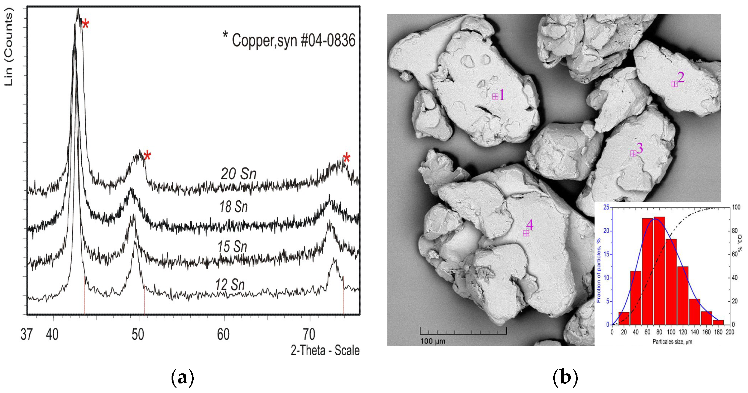
According to the XRD data, a single-phase solid solution is formed in mechanical alloying of copper and 12–20 wt.% tin for 20 min. XRD lines of the copper phase are broadened and shifted from 2-theta = 43.30° to 42.35° (
Figure 1a) due to the introduction of tin into the lattice of copper. However, in the case of mixtures with 18 and 20 wt.% Sn, the shift of 2-theta is smaller than in the case with 12 and 15% Sn. The copper lattice parameter
aCu of MA powders changes from 0.3667 to 0.3679 nm depending on the tin content (
Table 1), which is determined by Vegard’s rule. The tin concentration increases in the mixture from 15 to 20 wt.% which leads to a decrease in tin concentration
Xg from 8.4 to 5.5 at.% in a solid solution.
The MA solid solutions are nanocrystalline (
Table 1). The absence of tin-phase lines on the XRD patterns, as shown in (
Figure 1a), suggests that tin is distributed in the grain boundary areas, forming a more complex substructure. Specifically, it forms a grain boundary phase/solid solution of tin in copper. The increase in Sn segregation in the grain boundary could favor atomic interaction and ordered complex (associates) formation. Ones are stable structures and can be excluded from the diffusion process, which leads to a slowdown in grain boundary diffusion [
37]. A decrease in the level of microstrains for 20% Sn indicates the possibility of local ordering.
The analysis of the quantitative chemical composition data by EDX (
Table 2) obtained from a number of particles (
Figure 1b) showed that the powder of the MA alloys has a homogeneous composition and the average standard deviation of the chemical composition is not more than ~1.2%. The particle sizes reach 30–120 μm.
3.2. Structure of Mechanically Alloyed Cu-Sn-Ti Powders
The phase composition in the Cu-Ti-Sn ternary system is open to questions [
38]. The stable phase is CuSnTi, and the rest are copper-based supersaturated solid solutions [
39]. In the selected composition of Cu-20Sn -5Ti, two crystalline phases α + (Cu,Sn)
3Ti
5 are in equilibrium at a copper melting point of 1085 °C. The expected phase composition in the range of 300–600 °C is Cu
3Sn + Cu
2SnTi + α-phase. The δ-phase formation occurs at 600–700 °C and CuSnTi at 700–1085 °C in the concentration range of 3.0–6.5 wt.% Ti [
11].
Mechanical alloying in a ternary metal system can be carried out in two ways: one is the sequential MA with the preliminarily obtained solid solution and its subsequent alloying with titanium CuSn20-5Ti, and the second is the simultaneous alloying of the ternary composition of metal powders Cu-20Sn-5Ti.
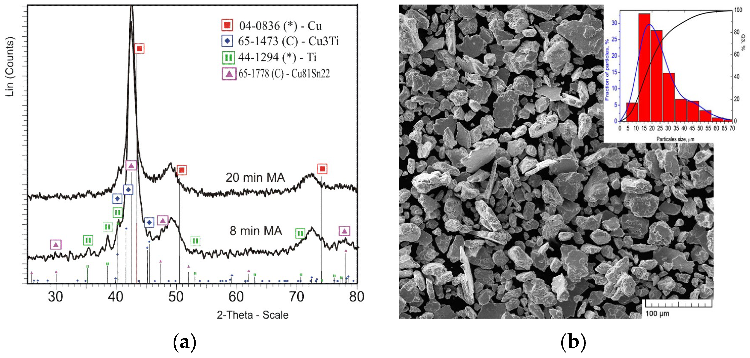
The sequential mechanical alloying of the preliminarily obtained powders of the solid solution CuSn20 with the
aCu = 0.3667 nm and titanium leads to negligible changes in the lattice parameter:
aCu = 0.3661 nm at 8 min of MA and
aCu = 0.3703 nm at 20 min of MA, which indicates the formation of a supersaturated solid solution. The crystallite size L
Cu(Sn,Ti) is ~8 nm. The α-Ti phase is still determined on XRD patterns for 8 min of MA and becomes X-ray amorphous after 20 min of MA. A small amount of the Cu
3Ti intermetallic compound is fixed (
Figure 2a). The particle sizes of the alloyed powder decrease to 7–40 µm (
Figure 2b).
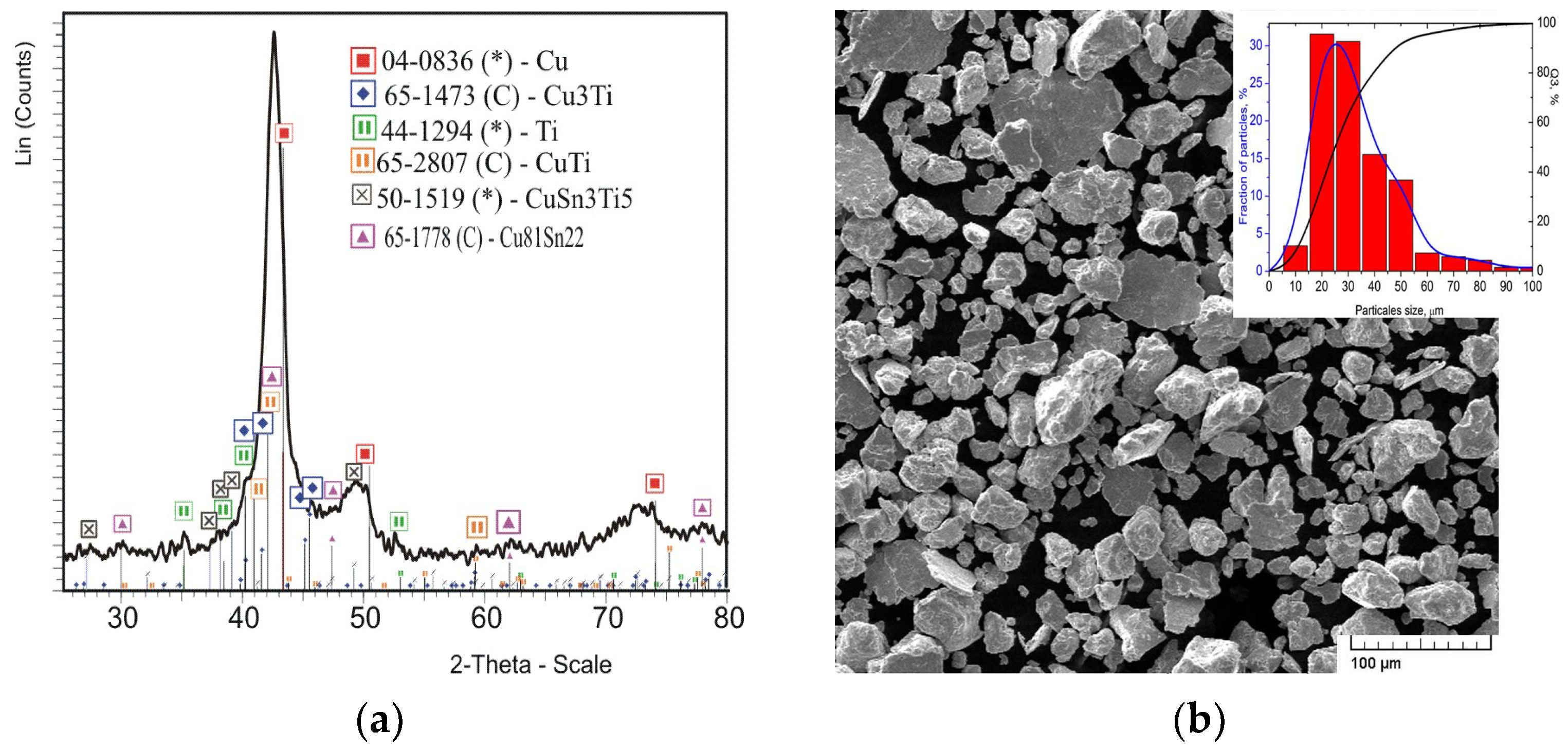
In simultaneous mechanical alloying of a ternary powder mixture Cu-20Sn-5Ti for 20 min, a copper-based solid solution with
aCu = 0.3691 ± 0.0001 nm and
LCu(Sn) = 8 nm is formed, too. The intermetallic compound δ-Cu
41Sn
11 and the ternary intermetallic CuSn
3Ti
5 are also formed. In addition, some part of copper remains unreacted and some traces of the titanium phase and its intermetallic compounds Cu
3Ti and CuTi are found in the mechanical alloy (
Figure 3a). The powder particle size is 11–48 μm (
Figure 3b), which is somewhat higher than in the case of sequential MA.
Thus, the sequential MA method makes it possible to form powders of nanostructured supersaturated solid solutions with a fine distribution of titanium in the grain boundary phase with Cu3Ti intermetallic inclusions. The joint MA of the Cu-Sn-Ti ternary composition for 20 min leads to the formation of a supersaturated solid solution as well, but the process does not go to the end. The unreacted part of copper, intermetallic compounds copper–tin Cu41Sn11, copper–titanium (CuTi, Cu3Ti) and copper–tin–titanium CuSn3Ti5 are present, which is associated with the variable concentration in local volumes during MA.
3.3. Structure of Mechanically Alloyed Fe-Ti Powders
According to the equilibrium state diagram [
40], two intermetallic phases, Fe
2Ti and FeTi, are formed in the Fe–Ti system. The limiting solubility of titanium in α-Fe does not exceed 9.8 at.% (
aFe = 0.2892 nm). However, the formation of a metastable phase of a supersaturated solid solution FeTi20 with
aFe = 0.2975 nm is possible [
41]. The iron limiting solubility in β-Ti is 22 at.% and 0.44 at.% in α-Ti at the eutectoid temperature.
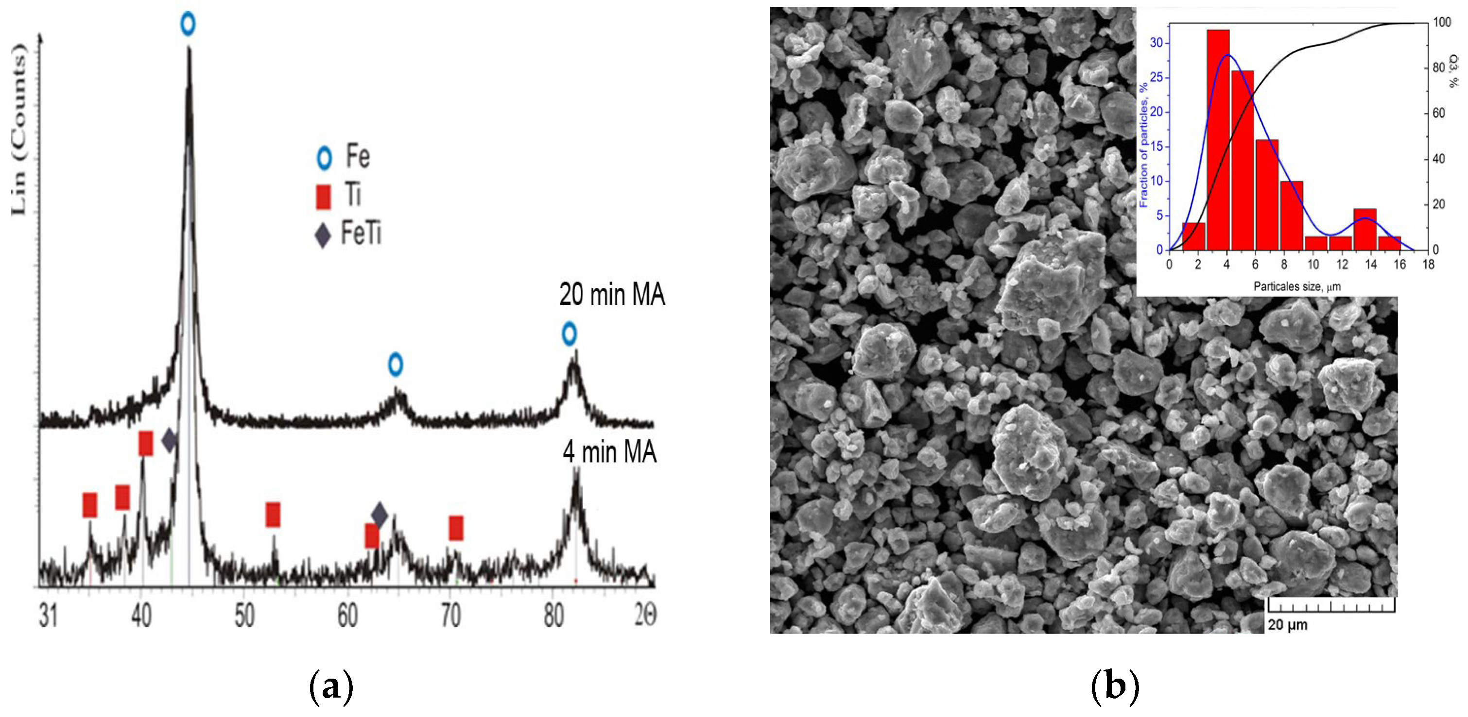
Mechanical alloying of mixture Fe-20 wt.% Ti for 4 and 20 min leads to the formation of an X-ray amorphous state of titanium, as is evidenced by the decrease in the intensities of α-Ti phase lines on the XRD patterns up to their complete disappearance (
Figure 4a). The α-Fe lines are broadened due to the decrease in the average size of iron crystallites
LFe to ~14 nm. The formation of the FeTi phase is possible as well. The asymmetric tails of the α-Fe lines to the region of the nearby FeTi phase reflections indicate the one. However, the iron lattice parameter
aFe is slightly increasing from 0.2866 nm to 0.2870 nm, which corresponds to the titanium content in the grain of no more than 2.3 at.%. It can be assumed that titanium is distributed along the grain boundaries and the formation of a grain-boundary solid solution with the local formation of FeTi is possible. The morphology of powders changes from aggregates at 4 min of MA to dense aggregates at 20 min of MA, and the particle sizes have two maxima of 4 µm (for Q
3 = 88%) and 13.5 µm (for Q
3 = 97%) (
Figure 4b). Thus, it is possible to synthesize powders of nanostructured iron-based composites with the distribution of X-ray amorphous refractory metal in the grain boundaries by mechanical alloying of iron with 20 wt. % titanium for 20 min.
3.4. Structure and Heat Resistance of Sintered Materials Based on Mechanically Alloyed Powders
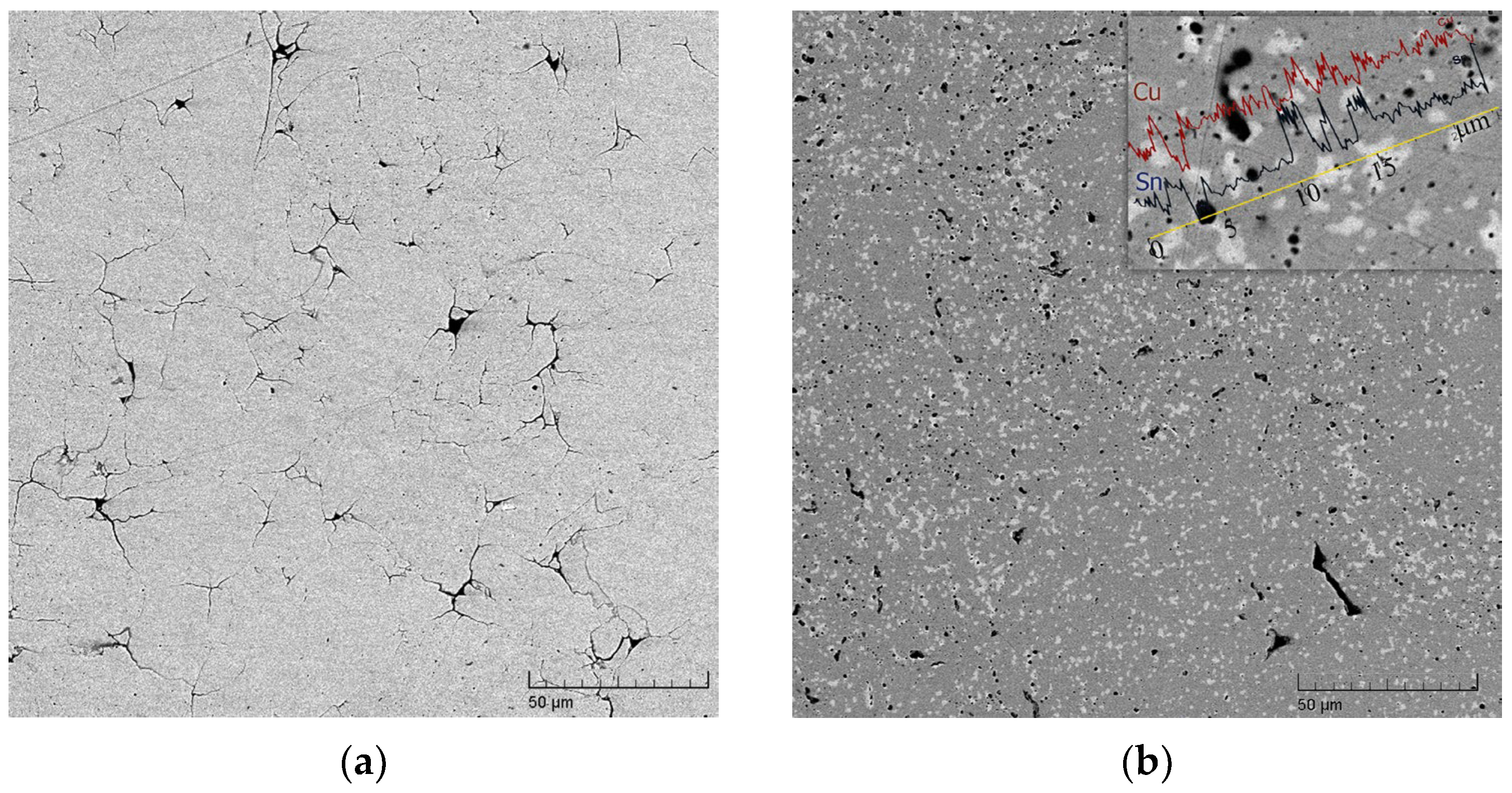
The structure of grain boundary layers affects the physical, mechanical and technological properties of powders. In particular, sintered materials made from mechanically alloyed powders of CuSn12 and CuSn15 exhibit non-porous structures, while CuSn18 and CuSn20 are sintered with the formation of pores (
Figure 5a), up to 8–10%.
The single-phase composition of the solid solution with the
aCu = 0.3679 ± 0.0001 nm is preserved in the sintered material based on CuSn12 powders, which corresponds to a tin content in the lattice of 6.8 at.%. This value does not change upon annealing up to 500 °C, but the crystallite size increases from 74 to 112 nm. The single-phase composition of the solid solution is also kept in the sintered material based on MA CuSn20 powders. However, the tin content in copper, as in the case of sintered materials at a low pressure of 10 MPa [
33], increases up to 8.7 at.% (
aCu = 0.3698 nm), but the crystallite size remains at the level of MA powder
L = 16–17 nm. The decomposition of a bulk solid solution with a decrease in the lattice parameter to 0.3669 nm is observed after low-temperature annealing at T = 250 °C, which is due to the precipitation of strengthening intermetallic compounds. The difference in the diffusion mobility of copper and tin during annealing at T = 520 °C additionally leads to the formation of small round pores (
Figure 5b).
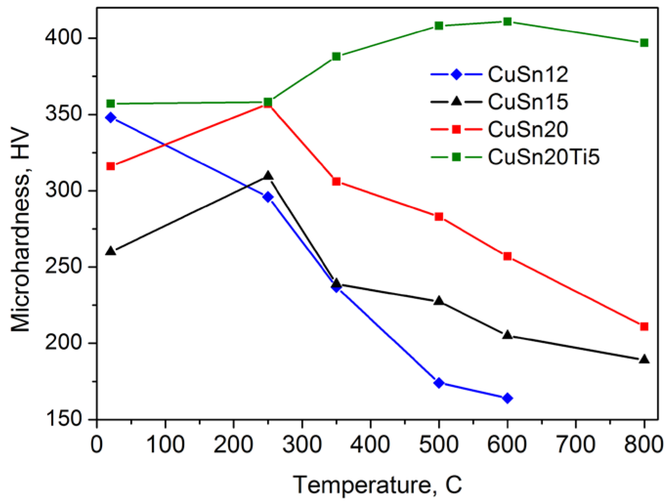
The microhardness of the sintered nanostructured material with the composition Cu-20%Sn is 308 ± 2 HV, and it is two times higher than that of the commercial material M2-01 with the same chemical composition. The increase in microhardness to 357 HV is noted at the solid solution decomposition temperature of 250 °C, followed by a linear decrease in microhardness to 204–255 HV at 600 °C (
Figure 6). The crystallite size increases from 17 to 68 nm.
The addition of titanium into the powder of the CuSn20 solid solution at a MA duration of 8 min contributes to the plastic deformation of the material with the formation of layered titanium inclusions in the sintered material (
Figure 7a), and after 20 min of MA, a structure of the eutectic type is formed (
Figure 7b).
The morphology of titanium inclusions changes from unequal to spherical ones with a decrease in size from 20 to 2 µm. The metal matrix is represented by phases of solid supersaturated solutions of Cu(Sn) and Cu(Sn,Ti) with inclusions of presumably ternary intermetallic compound CuSn
3Ti
5 (
Table 3). A similar structure is formed in alloys based on powders obtained by simultaneous mechanical alloying Cu-Sn-Ti.
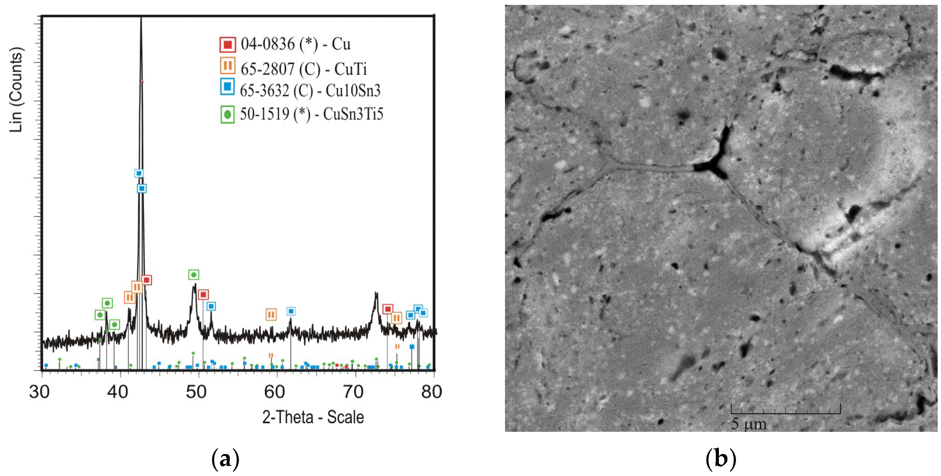
In sintered materials of the Cu-Sn-Ti composition, solid solutions decompose with the formation of intermetallic compounds CuTi and Cu
10Sn
3 (
Figure 8) in the temperature range of 350–800 °C, providing thermal hardening of materials with the achievement of a microhardness level of 357–408 HV (
Figure 6).
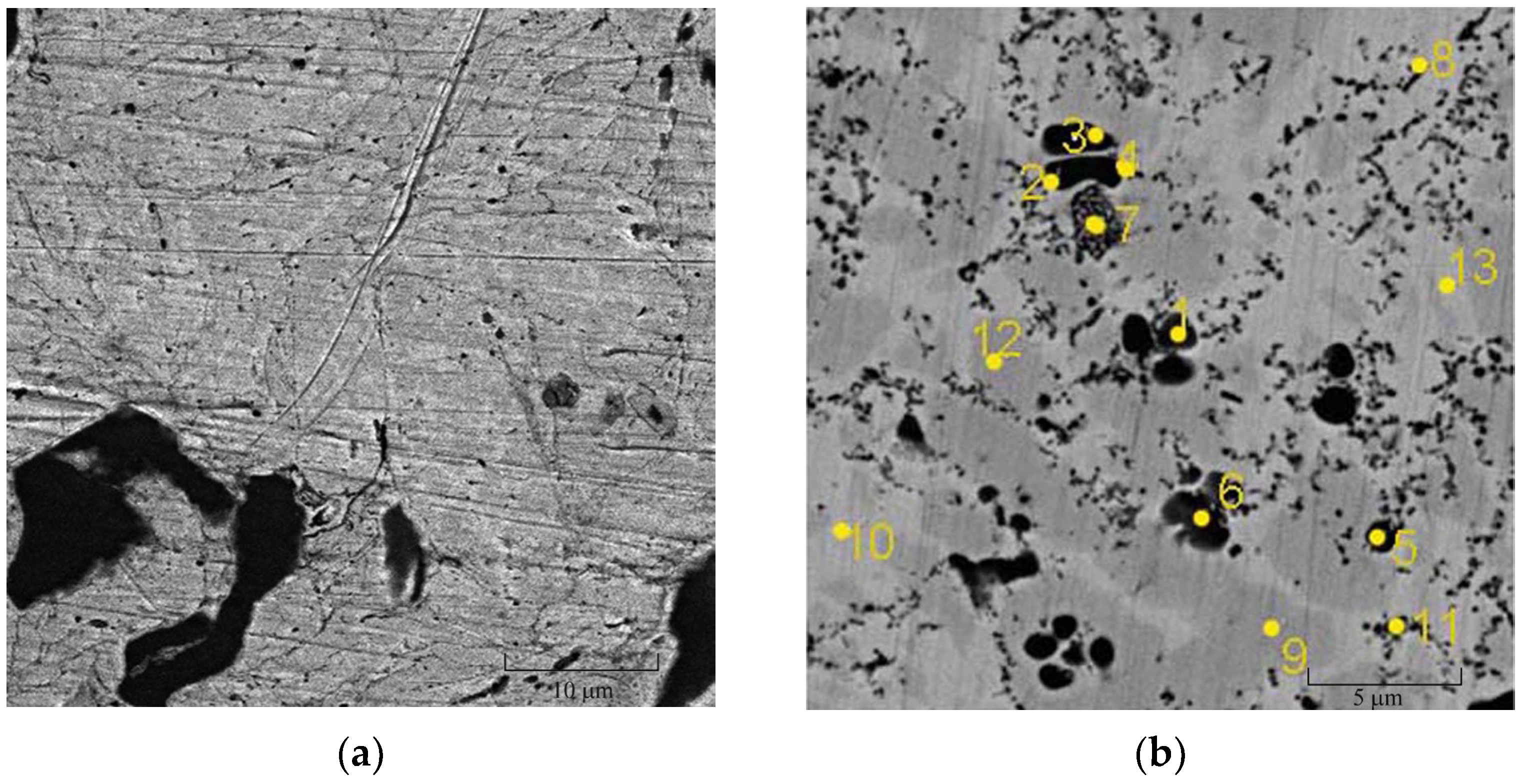
The sintering of FeTi20 powders obtained at 4 and 20 min of MA leads to the formation of eutectic-type alloys (
Figure 9). Based on the EDX data, primary polygonal grains of the solid solution α-Fe(Ti) with a titanium content of 6.9 ± 0.3 wt.% and eutectic α-Fe + Fe
2Ti are formed for 4 min of MA (
Table 4). In contrast, spherical grains of the α-Fe(Ti) with lower content (4.6 ± 1.4 wt.%)Ti are formed for 20 min of MA (
Table 5).
A spherical morphology indicates the possible formation of a liquid low-temperature eutectic (T 78 at.%Ti = 1085 °C), along with the presence of FeTi intermetallic compound.
Alloys exhibit a microhardness value ranging from 551–582 HV. Annealing the alloys at temperatures of 500–700 °C results in a minor increase in microhardness to 612–633 HV after 20 min of MA. However, when subjected to 4 min of MA, a decrease in microhardness to 510 HV is observed. The size of iron crystallites LFe under heating increases from 15 nm to 51 nm. This effect can be associated with the formation of the ternary oxide Fe3TiO3 and FeO. The high reactivity of the powders causes the presence of adsorbed oxygen on the surface of the MA powders and leads to internal oxidation under the subsequent heating of the alloy with the formation of the oxides.
Thus, the final structure of the sintered Cu-Sn-Ti alloy materials weakly depends on the way MA obtains alloys. Thermal hardening of alloys is observed under sintering due to the formation of a number of intermetallic compounds CuSn3Ti5, CuTi and Cu10Sn3. For materials of Fe-20%Ti composition, the eutectic alloy is formed, the morphology of which is dependent on the time of MA. The polygonal morphology of the primary grains of the iron solid solution transforms to the spherical one under sintering.
3.5. Tribological Properties of Sintered Materials Based on MA Powders
Based on the results of tribological tests (
Table 6), it can be concluded that high-tin alloys, obtained on the base of mechanically alloyed powders, exhibit increased wear resistance. Relative to the reference sintered material based on commercial powder alloy CuSn10P, the wear rate of it is reduced by more than 2 times and the friction coefficient is 1.4 times less. The addition of titanium increases the wear resistance of the MA alloy by 5 times.
3.6. Diamond Metal Matrix Composites
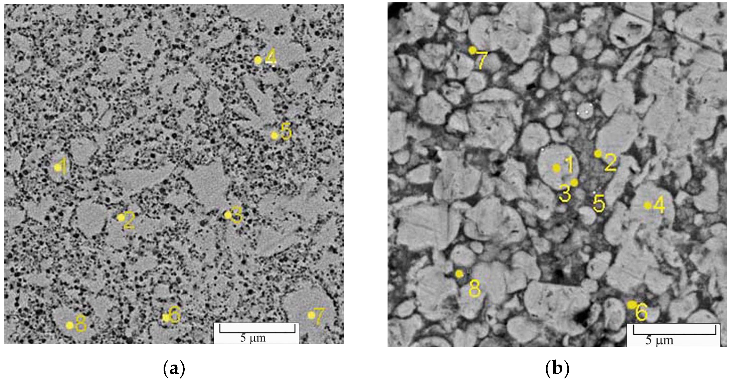
In sintered diamond metal matrix composites with the mechanically alloyed CuSn20 binder, no interactions of the components at the metal-to-diamond interface were observed, as in the case of commercial M2-01 binder. The material of the MA metallic binder does not wet the diamond, but the number of cracks and their length decrease. The use of titanium alloyed powders has an ambiguous effect on the structure and properties of the DMMC, which significantly depend on the way of their mechanical alloying (simultaneous or sequential). Thus, under simultaneous mechanical alloying of Cu-Sn-Ti powders, the high hardness and heterogeneity of the binder lead to an increase in the fragility of the DMMC with the formation of a network of cracks and chips (
Figure 10a).
A wide (up to 5 μm) region enriched in intermetallic compounds is formed at the diamond-to-binder interface (
Figure 10b). The formation of thin interlayers of titanium carbide TiC is possible.
When using powders obtained by a sequential mechanical alloying of the CuSn20-5Ti for 8 min, the traces of plastic flow of the binder material are observed at the diamond-to-binder interface (
Figure 11b), which is different from M2-01 (
Figure 11a). Single microcracks are possible.
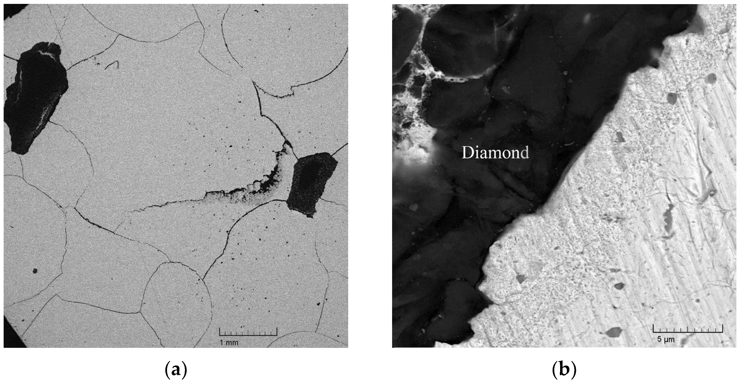
In the case of CuSn20-5Ti obtained by a sequential mechanical alloying for 20 min, no cracks are observed in the diamond metal matrix composite (
Figure 12a). The structure of the metal binder in the stress–strain region of the diamond remains unchanged. Local areas of TiC films with a thickness of 1–2 μm are possible at the interface, according to what the EDX analysis of the concentrations of titanium and carbon indicates (
Figure 12b).
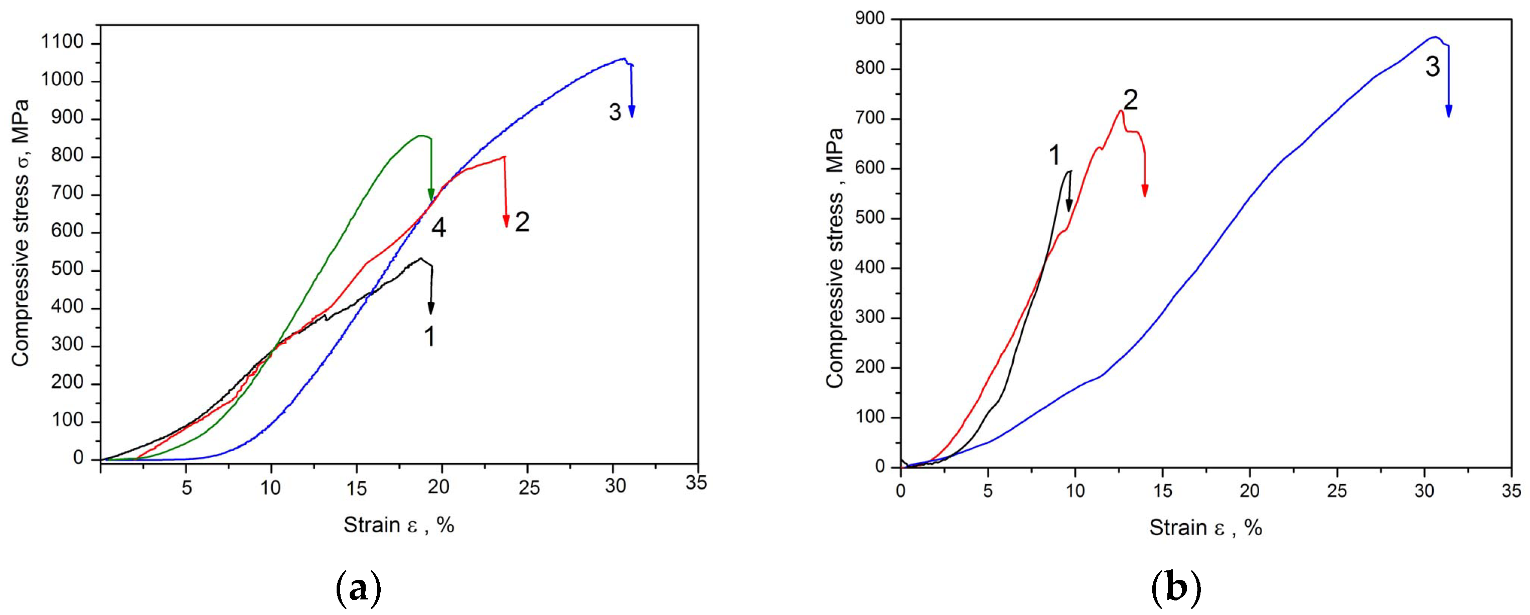
The compressive strength of such a DMMC increases by 1.6–2.0 times (up to 1000–1100 MPa) relative to samples with the M2-01 binder and the ductility of the composite increases to the level of strain ε of 30% (
Figure 13a). The strength of the DMMC with CuSn20 for 20 min of MA and the simultaneous Cu-20Sn-5Ti for 20 min of MA reaches the values of 798 and 857 MPa, respectively, but the ductility of the composites is reduced (ε = 18–24%).
The structural stability of the Fe-Ti binder material during sintering with diamond also depends on the distribution of titanium in the MA powder and the processing times.
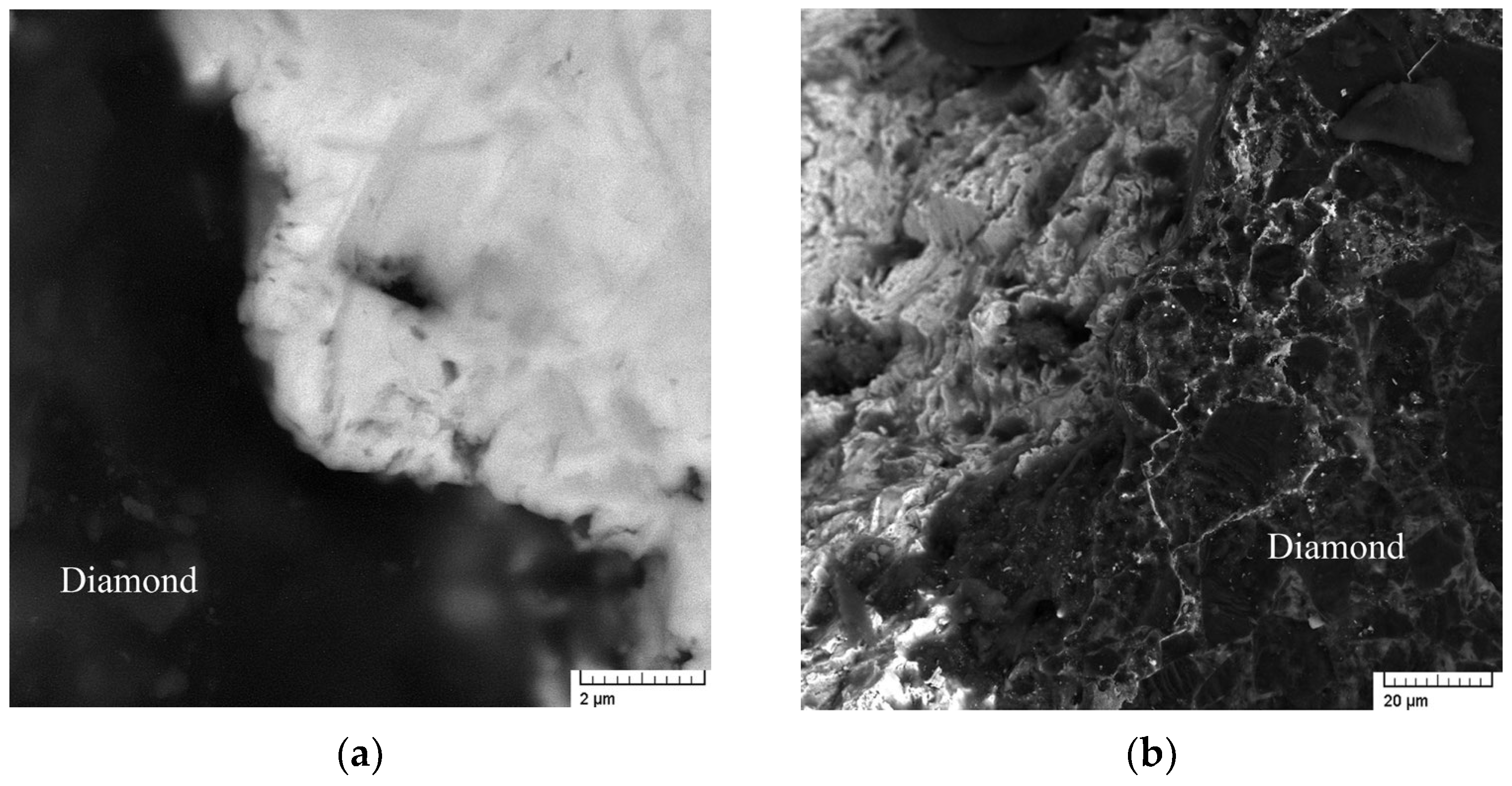
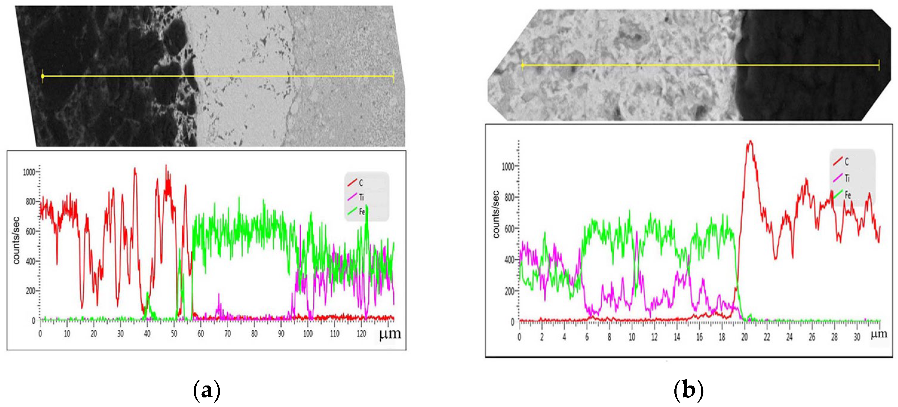
For example, in the case of using powder after 4 min of MA, the transition zone at the binder–diamond interface includes a layer containing carbon and iron up to 20 µm thick and a layer of iron 25–50 µm thick (
Figure 14a). Presumably, tensile stresses at the diamond/binder interface contribute to the depletion of the transition layer by the titanium due to diffusion with the formation of the α + Fe
2Ti eutectic structure in the matrix. The high activity of iron to diamond will contribute to the formation of both a solid solution of iron and its carbides. The composite material is brittle with a large number of cracks at the interface. This leads only to a slight increase in strength (by 18%) and the ductility of the DMMC regarding reference iron/diamond (
Figure 13b). An increase in the processing time to 20 min leads to stabilization of the material structure (
Figure 14b) during sintering with diamond, and no cracks are observed. On the diamond-to-binder interface, the formation of a thin TiC layer up to 1 μm is possible. The strength of DMMC and ductility increase simultaneously and reach σ = 860 MPa and ε = 30% (
Figure 13b).
Thus, an increase in the processing time makes it possible to obtain metal binders for metal/diamond composites with high heat resistance and improved performance properties. The mechanical alloying with titanium contributes to the formation of local thin carbide layers around the diamond grains: 1–2 μm of TiC in the case of Cu-based binder and up to 1 μm of Fe(C) and TiC in the case of Fe-based binder, which increases the adhesive strength of metal to diamond in the composite.
4. Discussion
According to experimental data, single-phase alloy powders in two-component mixtures Cu-20% Sn and Fe-20% Ti were obtained by mechanical alloying. However, with concentrations higher than the values of the maximum solubility (according to equilibrium diagrams), a saturation of a solid solution is low; for example, tin concentration in copper is up to 5 at.% and titanium concentration in iron is not more than 2 at.%. It can be assumed that the distribution of the alloying metal has a grain-boundary character, and both a segregation layer and a layer with the structure of a supersaturated solid solution can be formed. The mechanisms and processes of the grain-boundary phase formation have been studied and presented in a number of reviews [
42,
43,
44].
Structural changes are directly related to the interaction at interfaces, which are characterized by increased diffusion mobility relative to bulk processes (150 times higher) [
45]. Differences in the rate of diffusion along the grain boundaries and from the boundaries into the bulk of grains lead to inhomogeneity in the distribution of components with the formation of supersaturated boundary layers. For metallic systems with limited solubility and with chemical compounds, a two-phase model of the structure of a grain-boundary phase (GBP) [
37,
46,
47] was proposed. It can be considered as a quasi-atomic mixture of two components: a solid solution with a constant concentration at the level of the solubility limit and a composition containing associates (clusters) of a chemical compound without surface formation.
Thus, for alloys of the Cu-Sn system, an increase in the concentration of tin leads to the formation of a grain-boundary supersaturated solid solution under MA due to higher rates of diffusion along the grain boundaries. One can expect the formation of local grain boundary associates ordered according to the type of Cu
3Sn intermetallic compounds. In contrast to bronzes obtained by metallurgical methods, during the sintering of MA powder with a supersaturated grain-boundary solid solution, accelerated diffusion of tin from the boundaries into the grain volume occurs with the formation of a homogeneous metastable alloy of a supersaturated solid solution. The decomposition of the solid solution occurs upon heating, and it is accompanied by a decrease in the lattice parameter of copper due to the precipitation of the dispersed phase of the intermetallic compound, which leads to an increase in the microhardness and thermal stability of the material. In this case, the effect is already realized at a temperature of 250 °C, which is 100 °C lower than for cast bronzes [
48]. This can be facilitated by the presence of ordered associates in the grain-boundary phase, which can serve as nuclei of a new phase. Accordingly, the energy of their formation is reduced. With an increase in tin concentration, the effect of strengthening is more profound due to an increase in the amount of precipitated intermetallic compounds, while at 12 wt.% Sn, it is not realized (
Figure 6). A linear decrease in the microhardness under annealing in the temperature range of 350–800 °C can be associated with the coagulation of intermetallic compounds as a result of higher diffusion mobility. Thus, the use of MA promotes expanding the limits of tin in copper solubility due to supersaturated grain boundary regions.
During the mechanical alloying of pre-alloyed CuSn20 powders with titanium, the titanium particles are plastically deformed with the formation of thin interlayers. These interlayers provide a solid-phase interaction of the grain-boundary phase containing a solid solution supersaturated with tin. Due to the fact that Ti has a very low solubility for Cu-Sn intermetallic compounds [
49], one can expect the formation of ordered Ti
2Sn
3 clusters in GBP, which will contribute to the development of material ductility [
50], or Sn
3Ti
5, which has an extended Cu solubility [
39]. When the temperature rises above 350 °C, copper–titanium intermetallic compound CuTi and copper–tin β-phase Cu
10Sn
3 will evenly precipitate in the grain volume. Simultaneous mechanical alloying of the Cu-Sn-Ti ternary mixture can result in a probability distribution of local compositions, leading to complex interfacial reactions. As a consequence, a large amount of Cu-Ti and Cu-Sn intermetallic compound inclusions may be preserved, which can lower the ductility of the material. For mechanical alloying of Fe-Ti powders, it is important to consider the low solubility of titanium in the bulk of iron grains, resulting in the higher concentrations of titanium in the grain boundary regions, as well as the structural features of sintered alloys, the following structure of particles can be assumed. Titanium and intermetallics of Fe-Ti will remain in the grain boundary region after 4 min of MA. With an increase in time processing, the α-titanium transforms into β-titanium with the formation of a low-temperature eutectic. The formation of such a layer will make it possible to lower the sintering temperature of diamond-containing composites, which is important for preventing diamond degradation.
Sintering of the mixtures of the binder powders with diamond results in a stress-strain state, that depending on the ratio of the elastic energy of the particle and the elastic energy of the matrix, with the formation of plastic areas around particles [
51]. It will affect the distribution of the elemental composition of the binder. In the case of powders of ternary composition Cu-Sn-Ti by simultaneous MA, it can be assumed that high stresses in the deformed regions around the diamond leads to the decomposition of the solid solution with the release of hardening intermetallic compounds. In the case of MA of pre-alloyed nanostructured supersaturated solid solutions of copper–tin with titanium, ductility properties increase due to the rotational mechanism of grain boundary sliding [
52].
For powders Fe-20Ti at a short duration of MA, an increased diffusion mobility of titanium is noted, and under conditions of tensile stresses it contributes to the diffusion of titanium into the center of the matrix with the formation of a transition layer of iron near diamond. It’s unacceptable, since iron causes graphitization of diamond. The formation of β-titanium in grain-boundary regions at 20 min of MA leads to an increase in the solubility of iron in it, which, along with intermetallic compounds, contributes to the formation of a stable matrix structure. The possibility of the formation of local thin layers TiC upon contact with diamond also remains.


