Article

Mechanochemically Assisted Synthesis of Cu–Ag Microflakes

by
Alexander M. Vorobyev
,
Olga A. Logutenko
*,
Tatyana A. Borisenko
and
Alexander I. Titkov
Institute of Solid State Chemistry and Mechanochemistry, Siberian Branch of the Russian Academy of Sciences, Kutateladze Str. 18, 630090 Novosibirsk, Russia
*
Author to whom correspondence should be addressed.
Powders 2023, 2(2), 421-431; https://doi.org/10.3390/powders2020025
Submission received: 11 April 2023 / Revised: 19 May 2023 / Accepted: 29 May 2023 / Published: 1 June 2023
(This article belongs to the Special Issue Particle Technologies)

Abstract

:
In this work, a simple, inexpensive, and eco-friendly synthesis method of Cu−Ag microflakes has been developed. Firstly, Cu nanoparticles were synthesized by the reduction of copper nitrate in ethylene glycol at 180 °C in the presence of NaOH. The as-synthesized Cu powder was then dispersed in a mixture of ethyl alcohol and a dispersant followed by the mechanochemical treatment of the dispersion in a ball mill resulting in the formation of Cu flakes of approximately 0.2 μm thick and 2.7 μm lateral size. Next, by adding AgNO3 dissolved in H2O into the Cu particle dispersion, the bimetallic Cu−Ag microflakes were prepared. The particles so prepared were investigated by X-ray phase analysis and electron microscopy. It was shown that the Cu−Ag bimetallic particles were also flake-like in shape and similar in size to the original Cu microflakes. The effect of synthesis conditions, including parameters of mechanochemical processing, on thickness, size, and uniformity of the bimetallic microflakes was studied. The results obtained in this study were compared with those obtained by wet chemical synthesis alone. The flake-like Cu–Ag particles are supposed to be used in the manufacture of conductive pastes, adhesives, and composites for printed electronics.

1. Introduction

Copper, due to its high electrical conductivity, is widely used as conductive fillers in conductive inks and pastes. Monodispersed spherical copper particles with average particle sizes of around 1.0 µm are currently required for microelectronics application, particularly, for the fabrication of conductive materials for additive manufacturing. Spherical metal nano- and microparticles are widely used in current conductive inks and pastes. However, copper flakes have recently become much more popular as metallic fillers because the flake-like morphology, as compared with the spherical morphology, gives better electrical conductivity due to the increased contact area between the particles which are stacked in layers [1,2].
The abundance of copper and its low cost make it a suitable alternative to Ag or Au for commercial application, but copper is prone to oxidation, resulting in a decrease in conductivity. To overcome these drawbacks, Ag- or Au-coated Cu powders were shown to be used to prevent Cu nanoparticles from fast oxidation and, thus, to increase their stability in air [3,4,5,6]. Recently, many investigations have been focused on bimetallic nanoparticles, owing to their promising characteristics. Thus, it was reported that the paste based on Ag-coated Cu particles have higher electrical conductivity and better stability than Cu-based paste [4]. Kim et al. also showed that bimetallic Ag−Cu nanoparticles are more resistant to oxidation [5], while Zhu et al. [7] reported that the electrochemical migration resistance of Ag-plated copper-based paste was significantly higher than that of Ag-based paste, which provides the long-term reliability of electrically conductive adhesives. Thus, Cu–Ag nanoparticles, combining two metals, can be a functional material with improved physical and chemical properties, optimized cost, and possible protection of copper from oxidation. Apart from that, Cu–Ag bimetallic microflakes are of particular interest to apply to conductive pastes and inks for flexible printing electronics because of its high stretchability and conductivity, and stable electrical properties when stretched.
Cu–Ag bimetallic nanoparticles can be synthesized via various physical and chemical methods [8,9]. Typically, chemical reduction is used to produce Ag–Cu bimetallic nanoparticles with a wide range of size and different shapes. One of the most common approaches to prepare bimetallic Cu−Ag powders is the chemical reduction of copper and silver ions in polyols or in aqueous solutions with hydrazine or NaBH4 in the presence of PVP [3]. Galvanic replacement which relies on the spontaneous redox reaction between the atoms of a metallic substrate and a salt precursor, followed by the deposition of newly formed metal atoms on the substrate, also offers an alternative approach to the preparation of bimetallic nanostructures [10].
As known, in order to promote anisotropic crystal growth, the use of structure-directing agents, which can selectively adsorb certain crystal facets, is required. In most of the reported methods, various surfactants and polymers, including poly(vinylpyrrolidone) (PVP), have been widely used as structure-directing agents to induce the formation of flake-like structures [11,12,13]. However, the decomposition temperature of polymer-based stabilizers is too high and, therefore, PVP-coated particles are not applicable as inks for conductive printing on temperature-sensitive polymer substrates for low temperature processing. Apart from using structure-directing agents to obtain flake-like morphology, a simple and cheap method that can also be used is mechanical milling and it is widely used to produce nano- and microparticles, alloys, and some coatings [8,14]. Thus, the mechanical milling was applied on the spherical copper particles to prepare flake-like morphology first and then the electroless silver plating method was applied on the copper flakes to produce silver-coated copper flakes [8]. The authors showed that the Ag coating thickness depends both on the parameters of electroless plating and on the morphology of the copper particles. They also reported that the flake-like morphology played an active role in the reduction of silver ions on copper particles during the silver-coating process.
This study, therefore, explores the possibility of fabricating copper–silver bimetallic flake powder using a scalable one-pot process in which, copper micrometer particles of about 1 μm in size are first synthesized via the reduction of copper nitrate with ethylene glycol. Then, using wet bead milling, the copper particles are transformed into flake-like particles, followed by the formation of Cu–Ag bimetallic flakes using galvanic replacement between Cu flakes and Ag ions. Copper flakes can be formed by processing metal particles in a ball mill [1] but, to the best of our knowledge, no study has been completed on the use a combination of mechanical milling with galvanic replacement to prepare flake Cu–Ag powder. Mechanical milling technique has a number of advantages. First of all, it allows for better intermixing of the initial reagents thus accelerating the solid–liquid reaction rate to form a bimetallic compound and reducing the formation of metallic silver as the individual particles. In addition, the copper powders with flake-like morphology provide more reaction surface area to accelerate the reaction rate further.

2. Materials and Methods

2.1. Materials

Silver nitrate (AgNO3) of ≥99.9% purity grade (JSC “SoyuthKhimProm”, Saint-Petersburg, Russia), copper(II) nitrate trihydrate (Cu(NO3)2∙3H2O), 99% purity grade, Acros OrganicsTM), highly pure grade of sodium hydroxide (NaOH, 50% aqueous solution), ethylene glycol (HO(CH2)2OH, EG) of 99.9% purity grade, ≥99.7% pure 1,2-propylene glycol (CH3CH(OH)CH2OH, PG), 95% pure ethanol supplied by Khimmed (Moscow, Russia), and ≥90.0% DYSPERBYK dispersant (BYK), manufactured by BYK Chemie GmbH (Wesel, Germany) were used as received without further purification.

2.2. Synthesis of Copper Particles

Copper submicron particles were synthesized by the reduction of copper(II) nitrate by ethylene glycol. In a typical synthetic procedure, Cu(NO3)2 was first dissolved in ethylene glycol at a copper nitrate to ethylene glycol weight ratio of 1:10 under stirring. Then, the solution was heated to 180 °C with magnetic stirring and the sodium hydroxide solution at a copper to NaOH molar ratio of 1:1 was added to the reaction mixture. To complete the formation of copper particles, the reaction mixture was kept under continuous stirring at 180 °C for 10 min. After that, the mixture was air-cooled and the supernatant was decanted. The resulting precipitate was washed with ethanol to remove the impurities, dried in air at room temperature and further used for synthesis of Cu–Ag microflakes.

2.3. Synthesis of Cu and Cu–Ag Bimetllic Microflakes Using Mechanochemical Treatment

In the next step, the as-synthesized copper microparticles were mixed with ethyl alcohol (EtOH) and dispersant (BYK) at a Cu:EtOH:BYK mass ratio of 1:3:0.05, followed by the mechanochemical treatment of the mixture in an APS bead mill (VMA-Getzmann GmbH, Germany), at a rotational speed of 5000 rpm for 4 h. The bead-to-powder volume ratio was 13:1. Then, a 0.2 mol/L solution of silver nitrate in ethyl alcohol, at a Cu to Ag mass ratio of 70:30, was injected dropwise into the Cu microflakes dispersion at an injection rate of 0.5 mL/min. After the addition of silver nitrate was complete, the mixture was stirred for an additional 1 h; then, the particles were separated from the balls and dried in air.

2.4. Sample Characterization

X-ray diffraction (XRD) patterns were recorded on a D8 Advance powder X-ray diffractometer (Bruker AXS, Karlsruhe, Germany) equipped with a 1D Lynx-Eye detector and Ni-filtered Cu Kα radiation (0.02° 2θ step size and an accumulated time per step of 35.4 s). Phase identification was carried out using Powder Diffraction File (PDF) databases (ICDD, Release 2001). The crystallite size and lattice parameters were estimated by the Rietveld method [15] using software for the profile and structural analysis Topas 4.2 (Bruker AXS, Karlsruhe, Germany). Analysis of the samples by scanning electron microscopy (SEM) was performed using a Hitachi 3400 N scanning electron microscope (Hitachi Ltd., Tokyo, Japan) coupled with energy-dispersive spectrometer (EDS). The particle size distribution was calculated using SEM images on more than 100 particles. Differential scanning calorimetry (DSC) and thermogravimetric (TG) analyses were performed using a simultaneous thermal analyzer STA 449 F/1/1 JUPITER (Netzsch, Selb, Germany).

3. Results and Discussion

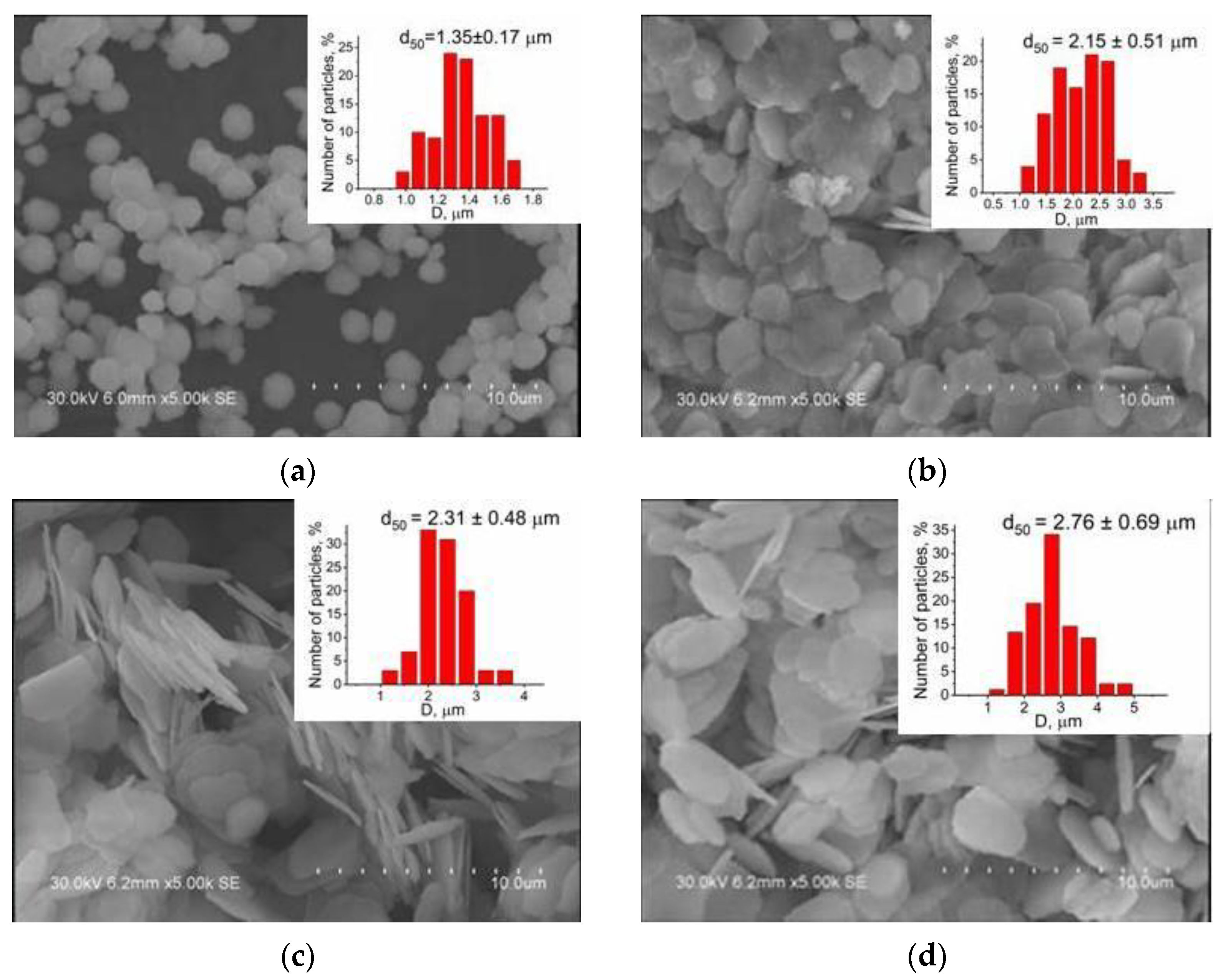
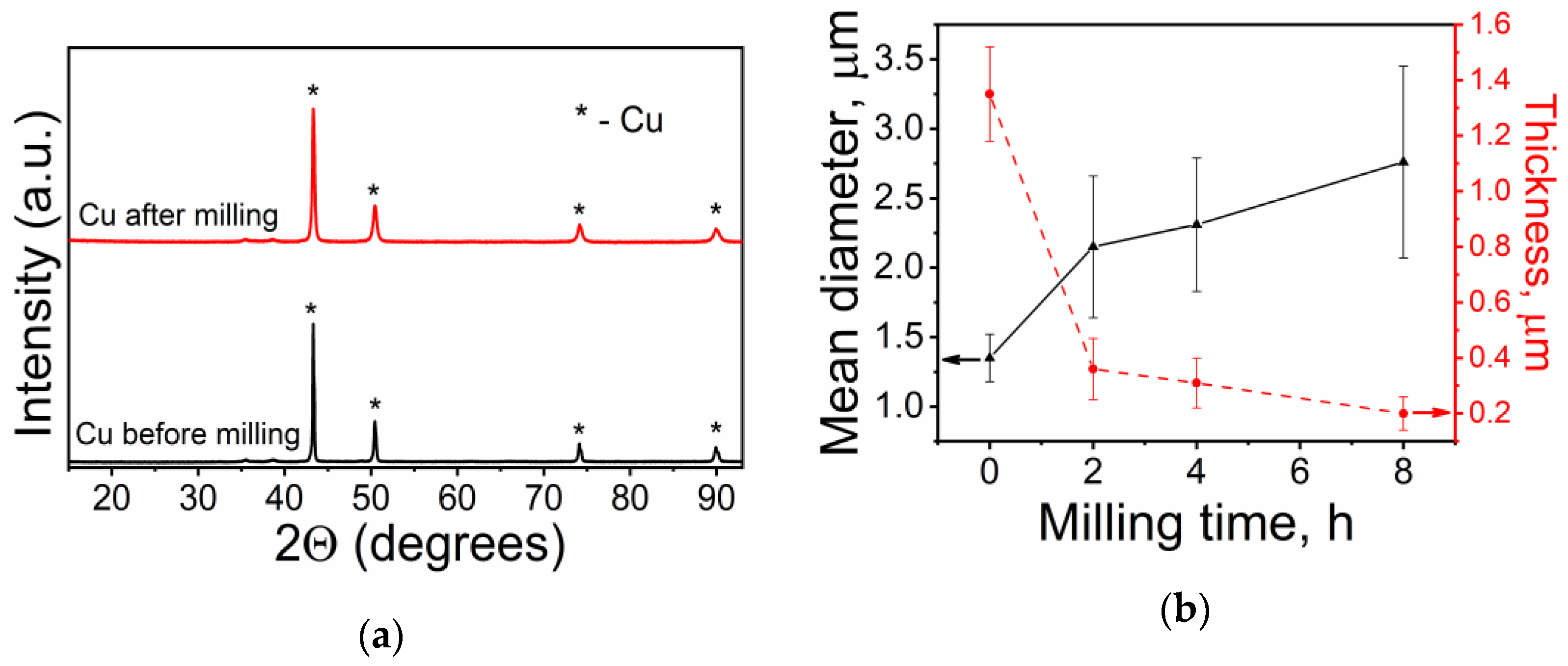
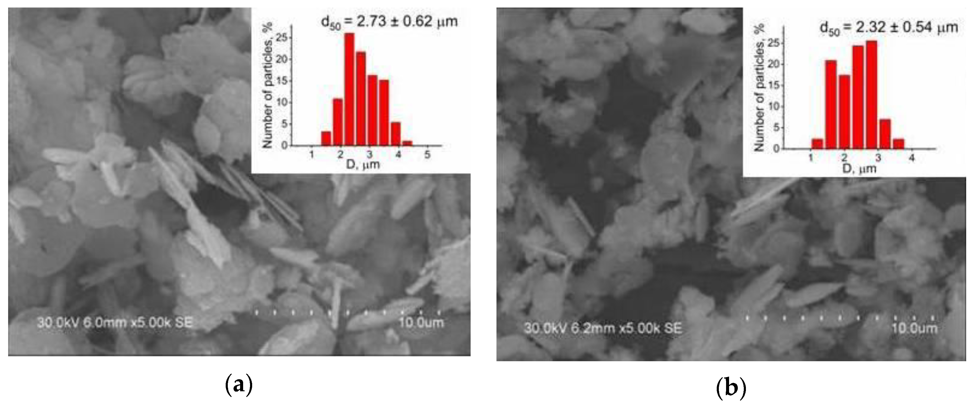
3.1. Effect of Milling Time and Ball-To-Powder Volume Ratio on Copper Powder Characteristics

Copper flakes were prepared by a two-step process which includes the reduction of copper nitrate with ethylene glycol at 180 °C with the formation of copper particles and follow-up processing of these particles in a wet bead mill resulting in a shape transformation from spheres to flakes. Figure 1 presents the SEM images and size distributions of the as-synthesized Cu particles before and after milling. As seen, prior to milling, the copper particles are nearly spherical in shape and have a relatively narrow size distribution of 1.35 ± 0.17 µm. The X-ray diffraction (XRD) pattern of the sample shows reflections at 2θ = 43.3, 50.4 and 74.2° (Figure 2a), corresponding to the crystalline planes of (111), (200), and (220) of metallic Cu (PDF 04-0836), and smallish peaks attributed to the Cu2O phase which means that the final copper particles prepared by the reduction of copper nitrate with ethylene glycol have been partly oxidized. The average crystallite size of the Cu particles before milling estimated by the Rietveld method is 114.8 ± 4.2 nm, while the lattice parameters a calculated from the XRD patterns is 3.616 ± 0.001 Å, which is consistent with the JCPDS card no. 04-0836 (a = 3.615 ± 0.001 Å).
In order to prepare copper flakes, the as-synthesized copper particles of 1.35 ± 0.17 µm in size were milled with ethyl alcohol as the solvent (EtOH) and DYSPERBYK as the dispersing agent (BYK). The change in morphology of the copper particles during milling is given in Figure 1b–d. As seen, after milling for 2 h, the morphology of the particles starts to change from spherical to flake-shaped structures, although some spherical Cu particles still remains unchanged. The flakes formed under these conditions have a lateral size of 2.15 ± 0.51 µm and they are about 0.4 µm in thickness. At a milling time of 4 h, all the particles are transformed into flakes of approximately of 2.31 ± 0.48 µm in size and 0.3 µm thick (Figure 1c), whereas after 8 h of milling, the size of the resultant flakes is 2.76 ± 0.69 µm and their thickness is nearly 0.2 µm. This change trend in morphology and dimensions can be explained as follows. Due to ductile nature of copper, in the initial stage of milling, impacts between beads and powders deform the particles and flake-shaped particles are formed. Further, as the milling time increases, the particles undergo shape deformation, namely, their thickness is decreased, as a result, the copper particles size in another dimension is increased. As seen in Figure 1c,d, the microflakes obtained after 4 and 8 h of milling have a relatively uniform size distribution and no other morphology was shown in the SEM images, indicating that all the particles were transformed into microflakes. With a further increase in milling time, the flake-like structure of copper powder becomes very thin and is gradually fractured into smaller particles.
XRD patterns of the flakes correspond to crystalline copper with smallish peaks of copper oxide, as in the case of copper particles before milling (Figure 2a). As can be seen, the intensities of the copper oxide peaks remain unchanged, indicating that milling the copper particles does not increase the amount of copper oxidation products in the microflakes. The average crystallite size of the Cu flakes estimated by the Rietveld method is 46.2 ± 1.8 nm, while the lattice parameters a calculated from the XRD patterns is 3.617 ± 0.001 Å, which is consistent with the JCPDS card no. 04-0836 (a = 3.615 ± 0.001 Å). Thus, the crystallite size of the Cu flakes is about 2.5 times smaller than that of the initial Cu particles prior to the milling. The reduction in the crystallite size can be attributed to the severe deformation of powder particles and the formation of crystal defects induced by high-energy ball milling [16].
The effect of bead-to-powder volume ratio on morphology and particle size of the milled Cu powders has been studied by scanning electron microscopy. It was shown that, when decreasing the bead-to-powder volume ratio from 13:1 (Figure 1c) to 6:1 (Figure 3), the morphology of the Cu particles and their size do not change. As seen from the figures, in both cases, the particles have flake-like shapes and their lateral sizes are 2.31 ± 0.48 and 2.33 ± 0.54 µm, respectively. However, at a bead-to-powder volume ratio of 6:1, the as-prepared flakes are thicker and less uniform than at a bead-to-powder volume ratio of 13:1. When this ratio increased from 13:1 to 30:1, the particles characteristics remained unchanged.

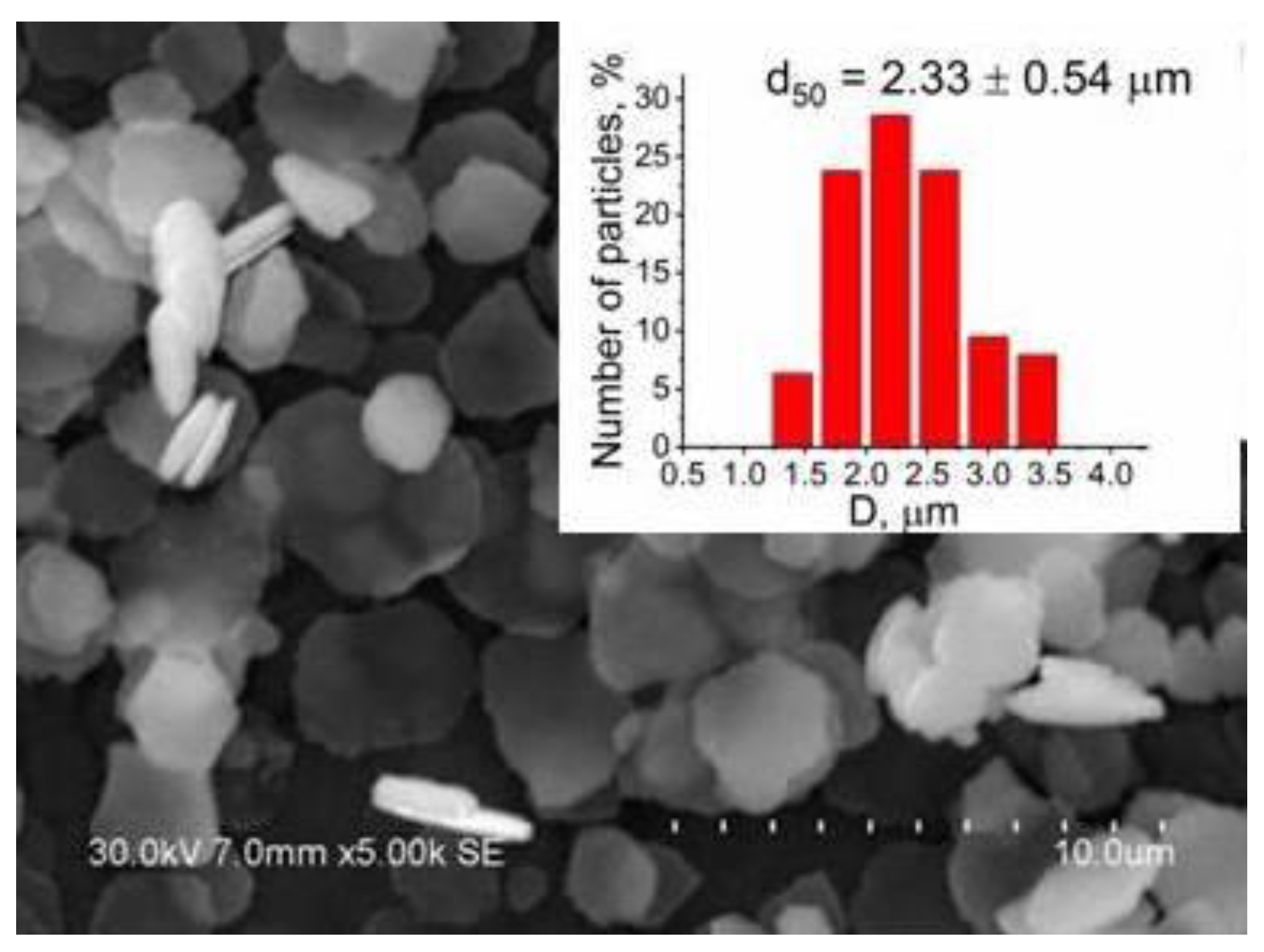
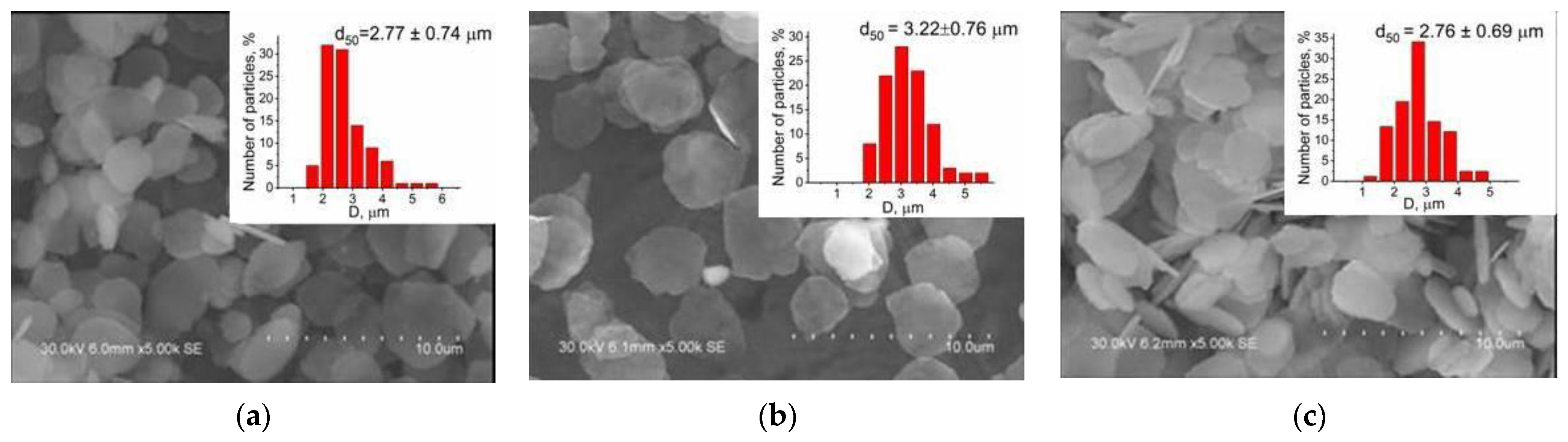
3.2. Effect of Bead Size and Milling Media

In order to optimize the mechanical milling process parameters, the effect of bead size and milling media on the lateral size and yield of the Cu flakes have been studied. It was shown (Figure 4a) that changing the milling media did not indicate any difference in the flake size. Thus, when changing ethanol to propylene glycol, the lateral flake sizes are 2.76 ± 0.69 and 2.77 ± 0.74 µm, respectively. The ratio of the copper microflakes in the powder does not change either.
It was also shown that an increase in the bead size from 0.1 to 0.4 mm results in a decrease in the mean powder size from 3.22 ± 0.76 to 2.76 ± 0.69 µm, as shown in Figure 4b,c. From the above results, it can be concluded that a size of milling beads of 0.4 mm and ethanol as the milling media are optimal for the production of monodisperse copper microflakes using mechanochemical treatment.

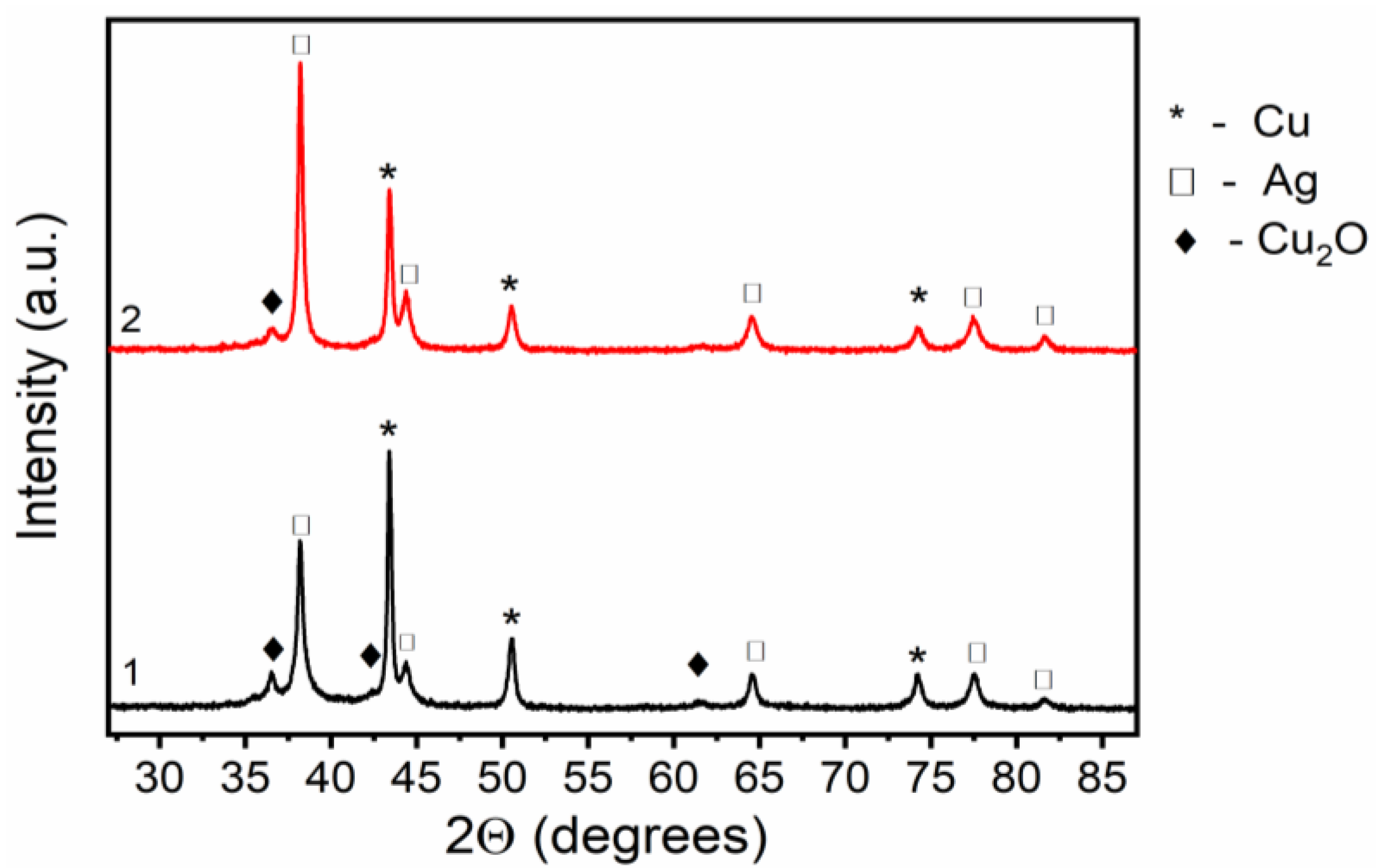
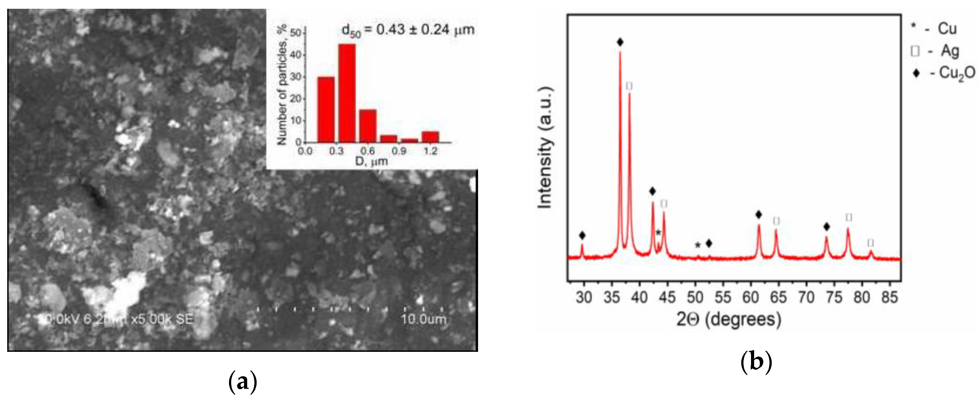
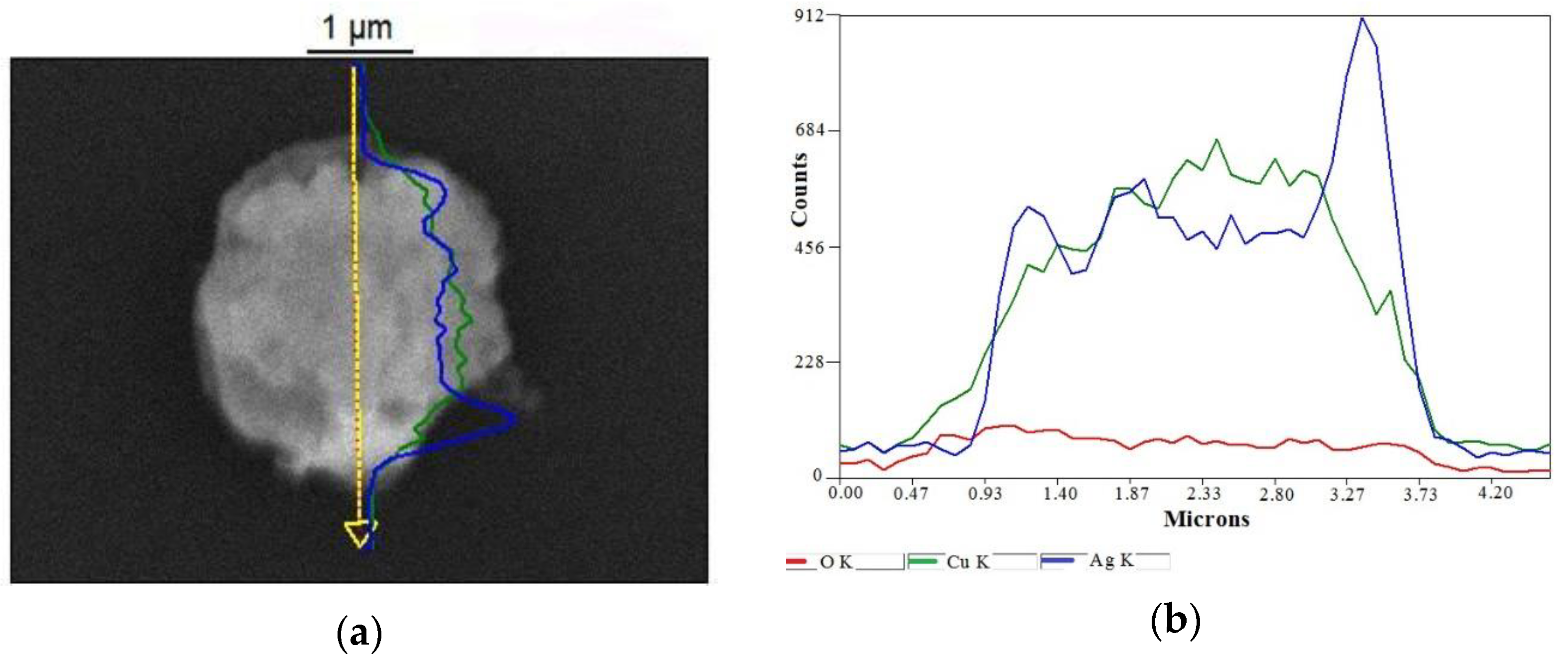
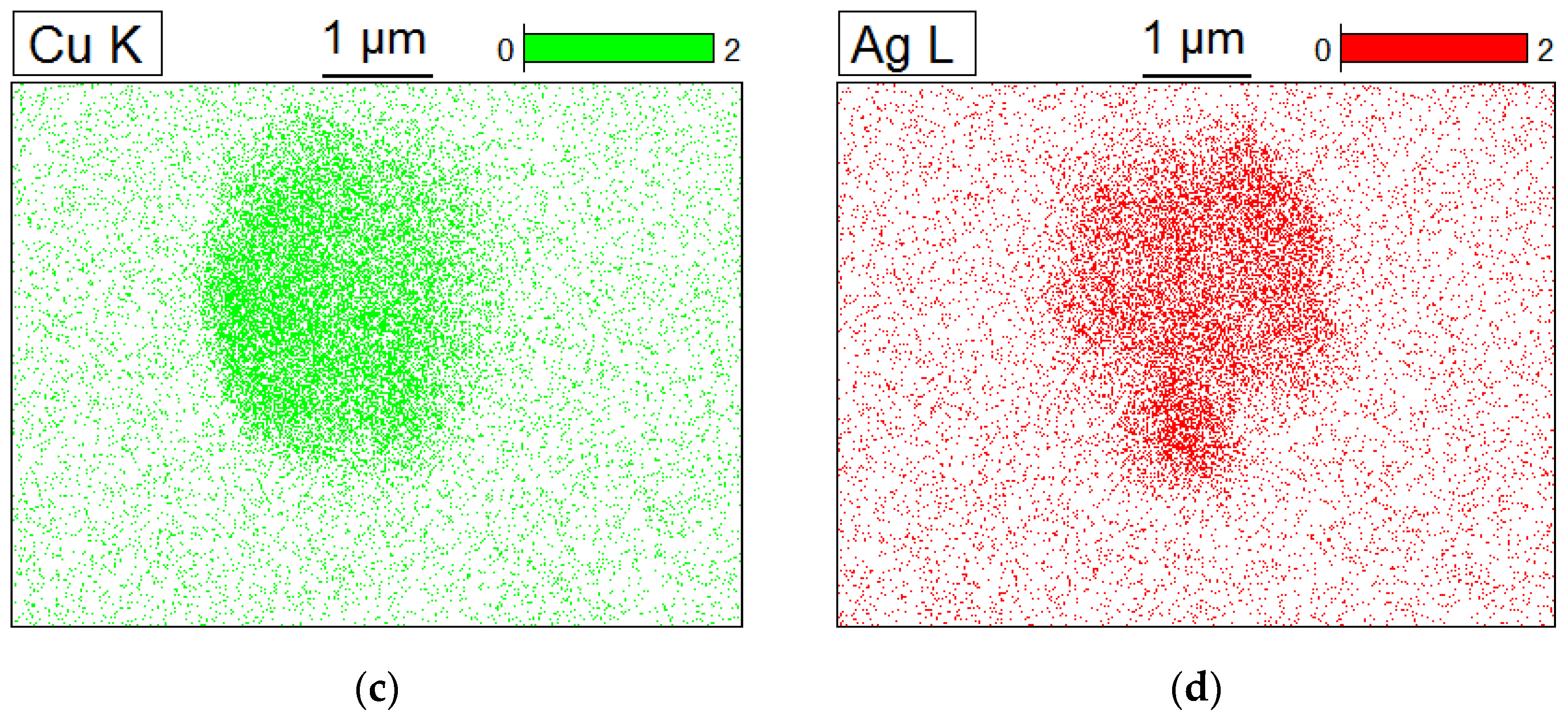
3.3. Preparation and Characterization of Cu−Ag Bimetallic Flakes

The formation of the Cu–Ag bimetallic particles occurs via the galvanic replacement mechanism by which copper is oxidized into ions dissolving in the solution while silver cations are reduced into atoms and deposited on the surface of the copper particles (Equation (1)). The galvanic replacement reaction is driven by the difference in redox potentials of the metals involved in the reaction system and that is the most important factor for the reaction. As a result, one metal is oxidized by ions of another metal having a higher reduction potential. The standard reduction potential of Ag+/Ag is higher than that of Cu2+/Cu (0.80 and 0.34 V vs. standard hydrogen electrode, respectively) due to which the spontaneous replacement of a copper atom by the two silver atoms occurs.
Cu + 2Ag+ = 2Ag + Cu2+
The effect of the mechanical milling process on the formation of bimetallic Cu–Ag particles has been studied. As seen from Figure 1d and Figure 5a, the mean particle sizes of the initial Cu and Cu–Ag milled powders are almost the same: 2.76 ± 0.69 and 2.73 ± 0.62 µm, respectively. Therefore, there is no difference in size and morphology between the initial Cu flakes and the sample prepared using a one-pot galvanic replacement between Cu microflakes and Ag precursor in a bead mill. For comparison, the galvanic replacement reaction was carried out in the absence of meachochemical treatment (Figure 5b). As seen, in the case of wet chemical synthesis alone, the average particle size of the powder decreases to 2.32 ± 0.54 μm. Apart from that, the as-prepared powder is less uniform and contains many small single particles of silver. This suggests that without mechanochemical treatment, silver ions are reduced to metallic silver in the solution and it does not form a silver layer on the copper flake surface.
The results of the XRD analysis for the as-synthesized particles are given in Figure 6. As can be seen, the three peaks at 43.3, 50.4, and 74.2° are assigned to the (111), (200), and (220) diffraction planes of the face-centered cubic structure of metallic Cu (JCPDS file no. 04-0836). The peaks located at 38.1, 44.1, and 64.4° in the pattern can be indexed to the diffraction from the (111), (200), and (220) planes of face-centered cubic Ag (JCPDS file no. 001-1164). This indicates that the as-synthesized sample is composed of Cu–Ag bimetallic structures. A small reflection at 2θ = 36.27° assigned to cubic phase Cu2O (111) (PDF 05-0667) is also detected in the XRD patterns of the as-synthesized Cu–Ag samples. However, as can be seen, for the sample obtained with the involvement of wet milling, its intensity is much less.

3.4. Effect of Dispersant

To determine the effect of dispersing agent BYK (a solution of an alkylammonium salt of a low-molecular-weight polycarboxylic acid polymer) on the formation of the Cu–Ag bimetallic particles, samples were prepared in the presence and absence of BYK, with similar milling conditions. As seen, the morphology of the powder prepared in the presence of BYK (Figure 4c) differs significantly from that processed without BYK (Figure 7a). Thus, in the absence of BYK, the particles are densely agglomerated and their average size is 0.43 ± 0.24 μm, whereas, when BYK is added as the dispersing agent in the starting mixture, after 4 h of milling, the powder is more dispersed and the formation of large flakes with a lateral size of 2.76 ± 0.69 µm takes place.
Figure 7b shows the XRD pattern of the powder prepared without BYK. As can be seen, the main diffraction peaks at 2θ = 29.6, 36.5, 42.4, 61,5, and 73.7°, corresponding to the (110), (111), (200), (220), and (311) planes, respectively, can be indexed to crystalline Cu2O according to the literature pattern (JCPDS, file no. 05-0667), while the peaks located at 38.1, 44.1, and 64.4° in the pattern can be indexed to the diffraction from the (111), (200), and (220) planes of face-centered cubic Ag (JCPDS file no. 001-1164). A very small reflection at 2θ = 43.3° assigned to the face-centered cubic structure of metallic Cu (JCPDS file no. 04-0836) just indicates that the as-synthesized sample is composed of Cu2O and Ag particles only, and that the formation of bimetallic, flake-like structures does not occur in the absence of BYK. Therefore, we can suggest that BYK is adsorbed on the surface of the particles, thus playing an important role for Cu–Ag microflakes formation, first of all, preventing copper microflakes from oxidation.
To confirm the formation of bimetallic structure and to identify the element distribution in Cu–Ag microflakes, elemental mapping and line profile analysis were carried out. Figure 8b shows the distributions of the Cu and Ag elements along the cross section yellow line shown in Figure 8a. As can be seen, the X-ray element mapping clearly indicates the presence of both copper phase and silver phase in the selected microflake, thus confirming the formation of Cu–Ag bimetallic structure.

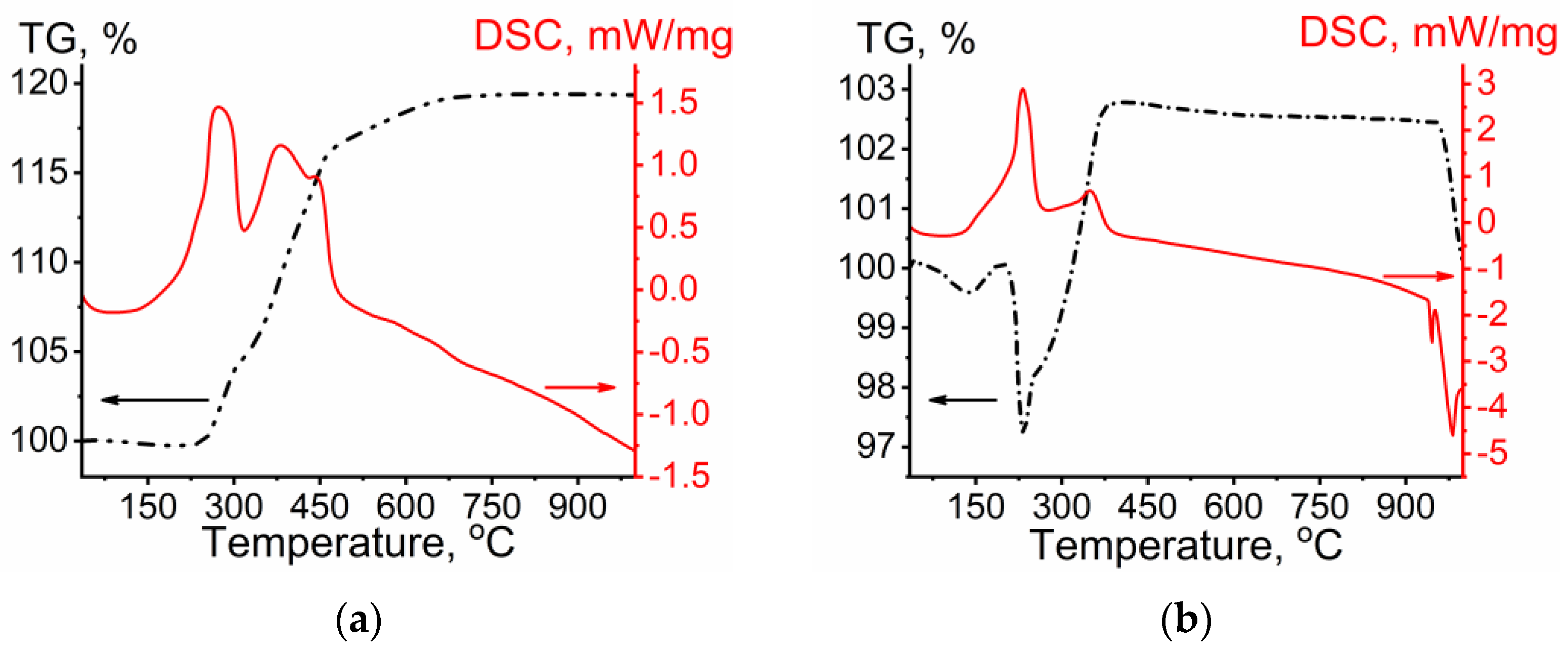
3.5. Thermal Behavior of Cu and Cu−Ag Flakes

The thermal behaviour of the Cu and Cu–Ag bimetallic particles in air were studied using thermogravimetric analysis (Figure 9). As seen in Figure 9a, a weight gain because of the oxidation of copper with the gradual increase in temperature starts at around 250 °C. The first step in weight gain up to ~16% occurs in a temperature range of 250–450 °C and it can be attributed to the formation of Cu2O. The exothermic peak at about 275 °C on the DSC curve also shows the formation of Cu2O [17]. A further increase in the mass of the sample up to 18.5% occurs in a fairly large temperature range (350–750 °C) and it can be related to the formation of CuO. The distinct exothermal peak at 375 °C on the DSC curve is attributed to the formation of CuO [17]. There is no weight change above 750 °C as all the copper has been converted to oxides completely.
The TGA and DSC plots of the as-synthesized Cu–Ag bimetallic particles are shown in Figure 9b. It can be seen that, at 150 °C, there is a decrease in the mass of the sample of approximately 0.5% which probably comes from the loss of a volatile component of the dispersant adsorbed on the Cu–Ag particles. A further decrease in the mass of the sample of ~3% in a temperature range of 200–240 °C can probably be attributed to the decomposition of the dispersant adsorbed on the particle surface, and it corresponds to the exothermic peak at about 240 °C on the DSC curve. After the TGA curve decrease in the 200–240 °C range, a weight gain because of the oxidation of copper with the gradual increase in temperature starts at around 250 °C. The plot keeps rising up to 380 °C with an increase in the mass of the sample up to 5.6% which can be associated with the rapid oxidation of copper with the formation of Cu2O. The latter is attributed to the Cu that are not totally covered by Ag and are exposed to atmospheric oxygen. Therefore, the total weight gain because of the copper oxidation in the case of Cu–Ag bimetallic particles is almost three times less than that in the case of Cu alone, thus demonstrating the higher thermal stability of the Cu–Ag sample.

4. Conclusions

A simple approach to prepare Cu−Ag microflakes using a combination of galvanic replacement between Cu and Ag+ and mechanical treatment has been demonstrated. The wet bead-milling was used to transform mostly spherical copper particles into flakes. An increase in the wet bed-milling time of copper particles was shown to increase the lateral size of the flakes from 2.15 ± 0.51 to 2.76 ± 0.69 µm and to decrease their thickness from 0.4 to 0.2 µm. Cu flakes of 2.76 ± 0.69 µm in lateral size and approximately 0.2 µm thick were employed as starting material to produce Cu–Ag bimetallic flakes. Mechanochemical treatment was shown to significantly improve uniformity of the bimetallic Cu−Ag structures and their oxidative stability. Mechanochemically assisted synthesis results in the precipitation of Ag on copper flakes to form a bimetallic Cu−Ag structure, while without the mechanochemical treatment, most of the silver particles are mainly formed in the solution. The use of BYK as the dispersing agent during mechanical treatment efficiently prevents copper particles from oxidation and leads to the formation of bimetallic Cu–Ag microflakes. The as-synthesized flake-like Cu–Ag particles can be used as metallic fillers to produce electrically conductive pastes, adhesives, and composites for printing electronics.

Author Contributions

Conceptualization, A.I.T.; investigation, A.M.V. and T.A.B.; data curation, A.M.V. and O.A.L.; writing—original draft preparation, O.A.L.; writing—review and editing, A.I.T. and O.A.L.; visualization, T.A.B. and A.M.V.; supervision, A.I.T. and O.A.L.; project administration, A.I.T. All authors have read and agreed to the published version of the manuscript.

Funding

This research was funded within the state assignment to ISSCM SB RAS (Project No. 122032900069-8).

Institutional Review Board Statement

Not applicable.

Informed Consent Statement

Not applicable.

Data Availability Statement

Not applicable.

Conflicts of Interest

The authors declare no conflict of interest. The funders had no role in the design of the study; in the collection, analyses, or interpretation of data; in the writing of the manuscript; or in the decision to publish the results.

References

  1. Rosen, Y.; Marrach, R.; Gutkin, V.; Magdassi, S. Thin copper flakes for conductive inks prepared by decomposition of copper formate and ultrafine wet milling. Adv. Mater. Technol. 2019, 4, 1800426. [Google Scholar] [CrossRef]
  2. Tam, S.K.; Fung, K.Y.; Ng, K.M. Copper pastes using bimodal particles for flexible printed electronics. J. Mater. Sci. 2016, 51, 1914–1922. [Google Scholar] [CrossRef]
  3. Tan, K.S.; Cheong, K.Y. Advances of Ag, Cu, and Ag–Cu alloy nanoparticles synthesized via chemical reduction route. J. Nanopart. Res. 2013, 15, 1537–1566. [Google Scholar] [CrossRef]
  4. Nishikawa, H.; Mikami, S.; Miyake, K.; Aoki, A.; Takemoto, T. Effects of silver coating covered with copper filler on electrical resistivity of electrically conductive adhesives. Mater. Trans. 2010, 51, 1785–1789. [Google Scholar] [CrossRef]
  5. Kim, N.R.; Shin, K.; Jung, I.; Shim, M.; Lee, H.M. Ag−Cu Bimetallic nanoparticles with enhanced resistance to oxidation: A combined experimental and theoretical study. J. Phys. Chem. C 2014, 118, 26324–26331. [Google Scholar] [CrossRef]
  6. Titkov, A.I.; Logutenko, O.A.; Vorobyov, A.M.; Gerasimov, E.Y.; Shundrina, I.K.; Bulina, N.V.; Lyakhov, N.Z. Synthesis of ~10 nm size Cu/Ag core-shell nanoparticles stabilized by an ethoxylated carboxylic acid for conductive ink. Colloids Surf. A Physicochem. Eng. Asp. 2019, 577, 500–508. [Google Scholar] [CrossRef]
  7. Zhu, X.; Liu, Y.; Long, J.; Liu, X. Electrochemical migration behavior of Ag-plated Cu-filled electrically conductive adhesives. Rare Metals 2012, 31, 64–70. [Google Scholar] [CrossRef]
  8. Güler, O.; Varol, T.; Alver, Ü.; Çanakçı, A. The effect of flake-like morphology on the coating properties of silver coated copper particles fabricated by electroless plating. J. Alloys Compd. 2019, 782, 679–688. [Google Scholar] [CrossRef]
  9. Shang, R.; Gong, X.; Li, Y.; Teng, J. Flake Cu-5Ag alloy powder with enhanced oxidation resistance via aging. Adv. Powder Technol. 2023, 34, 103921. [Google Scholar] [CrossRef]
  10. Cheng, H.; Wang, C.; Qin, D.; Xia, Y. Galvanic replacement synthesis of metal nanostructures: Bridging the gap between chemical and electrochemical approaches. Accounts Chem. Res. 2023, 56, 900–909. [Google Scholar] [CrossRef] [PubMed]
  11. Zhang, Y.; Zhu, P.; Li, G.; Cui, Z.; Cui, C.; Zhang, K.; Gao, J.; Chen, X.; Zhang, G.; Sun, R.; et al. PVP-mediated galvanic replacement synthesis of smart elliptic Cu-Ag nanoflakes for electrically conductive pastes. ACS Appl. Mater. Interfaces 2019, 11, 8382–8390. [Google Scholar] [CrossRef] [PubMed]
  12. Wickramaarachchi, K.; Sundaram, M.M.; Henry, D.J.; Gao, X. Alginate biopolymer effect on the electrodeposition of manganese dioxide on electrodes for supercapacitors. ACS Appl. Energy Mater. 2021, 4, 7040–7051. [Google Scholar] [CrossRef]
  13. Wickramaarachchi, K.; Sundaram, M.M.; Henry, D. Surfactant-mediated electrodeposition of a pseudocapacitive manganese dioxide a twofer. J. Energy Storage 2022, 55, 105403. [Google Scholar] [CrossRef]
  14. Canakci, A.; Erdemir, F.; Varol, T.; Dalmi, R.; Ozkaya, S. Effects of a new pre-milling coating process on the formation and properties of an Fe-Al intermetallic coating. Powder Technol. 2014, 268, 110–117. [Google Scholar] [CrossRef]
  15. Rietveld, H.M. A profile refinement method for nuclear and magnetic structures. J. Appl. Cryst. 1969, 2, 65–71. [Google Scholar] [CrossRef]
  16. Chen, X.; Teng, J.; Xu, Z.; Li, Y. Effect of ball-to-powder weight ratio on microstructure evolution of nanocrystalline Mg-Zn powders prepared by ball milling. Indian J. Eng. Mater. Sci. 2019, 26, 126–134. [Google Scholar]
  17. Leitner, J.; Sedmidubsky, D.; Lojka, M.; Jankovsky, O. The effect of nanosizing on the oxidation of partially oxidized copper nanoparticles. Materials 2020, 13, 2878. [Google Scholar] [CrossRef] [PubMed]
Figure 1. SEM micrographs and particle size distributions of the Cu powder before (a) and after milling for 2 (b), 4 (c), and 8 (d) h at a bead-to-powder volume ratio of 13:1.
Powders 02 00025 g001
Figure 2. XRD patterns of the particles prepared by reduction of Cu(NO3)2 with ethylene glycol at 180 °C before and after milling for 4 h (a) and variation of the average flake diameter and thickness as a function of milling time (b).
Powders 02 00025 g002
Figure 3. SEM micrograph and particle size distribution of the Cu powder after milling for 4 h at a bead-to-powder volume ratio of 6:1.
Powders 02 00025 g003
Figure 4. Variation of the lateral flake size as a function of milling media and bead size. Milling media: propylene glycol (a) and ethanol (b,c); bead size: 0.1 (b) and 0.4 (a,c) mm.
Powders 02 00025 g004
Figure 5. SEM micrographs of the particles prepared by adding a silver nitrate solution to the copper microflakes with milling (a) and without milling (b) in ethanol.
Powders 02 00025 g005
Figure 6. XRD patterns of the particles prepared by adding a silver nitrate solution to the copper microflakes without milling (1) and with milling in ethanol (2).
Powders 02 00025 g006
Figure 7. SEM micrograph (a) and XRD pattern (b) of the particles prepared by adding a silver nitrate solution to the copper microflakes in ethanol without BYK.
Powders 02 00025 g007
Figure 8. SEM energy-dispersive X-ray spectroscopy (EDS) data of the Cu–Ag bimetallic particles prepared by adding a silver nitrate solution to the copper microflakes with milling in ethanol. (a) Distributions of Cu and Ag particles along the cross-section line on a single microflake; (b) Elemental line profiles of Cu–Ag particle; (c,d) the energy-dispersive X-ray elemental maps of copper and silver.
Powders 02 00025 g008aPowders 02 00025 g008b
Figure 9. TGA and DSC curves of the Cu (a) and Cu–Ag (b) particles with a heating rate of 10 °C·min1.
Powders 02 00025 g009
Disclaimer/Publisher’s Note: The statements, opinions and data contained in all publications are solely those of the individual author(s) and contributor(s) and not of MDPI and/or the editor(s). MDPI and/or the editor(s) disclaim responsibility for any injury to people or property resulting from any ideas, methods, instructions or products referred to in the content.

