Article

Hybrid Polyurethane/Polypyrrole Composite Coatings on Passivated 316L SS for Surface Protective Action against Corrosion in Saline Medium

by
Arumugam Madhan Kumar
1,*,
Akeem Yusuf Adesina
1,
Jothi Veeramani
2,
Mohammad Mizanur Rahman
1 and
J. S. Nirmal Ram
2
1
Interdisciplinary Research Center for Advanced Materials, King Fahd University of Petroleum & Minerals (KFUPM), Dhahran 31261, Saudi Arabia
2
Center for Research and Development, PRIST University, Thanjavur 613403, Tamil Nadu, India
*
Author to whom correspondence should be addressed.
Corros. Mater. Degrad. 2022, 3(4), 612-627; https://doi.org/10.3390/cmd3040033
Submission received: 23 June 2022 / Revised: 25 October 2022 / Accepted: 26 October 2022 / Published: 31 October 2022
(This article belongs to the Special Issue Corrosion Barrier Coatings)

Abstract

:
Hybrid treatments consisting of surface modification and subsequent protective coatings have gained extensive attention among corrosion mitigation approaches for a wide variety of structural metallic materials. This study aims to review the enhancement of the corrosion protection performance of polyurethane (PU) coatings on 316L stainless steel (SS) specimens. This was achieved via a two-step strategic treatment, primarily by electrochemical passivation and subsequent deposition of PU composite coatings with the different feed ratio of synthesized polypyrrole (PPy) nanoparticles. The effect of different applied voltage on the surface features and the corrosion behavior of the passivated SS surfaces was systematically investigated using surface characterization techniques and a potentiodynamic polarization test in a NaCl solution. Surface morphological images revealed the porous structure on the passivated surface. It is inferred from the topographical surface results that homogeneous surface roughness was achieved with the applied voltage of 5 V. Infra-red spectroscopic results validate the formation of PU/PPy composite coatings and the intermolecular chemical interaction between the PU and PPy moieties. Furthermore, corrosion measurements corroborate the improved corrosion resistance of PU/30PPy coatings with higher values of charge transfer resistance, Rct (1.0869 × 10⁷ Ω cm2), and film resistance, Rf (2.258 × 10⁵ Ω cm2), with the lowest values of corrosion, icorr (4.7 × 10⁻³ µA cm−2) compared to that of the PU/Bare specimen. In conclusion, it is confirmed that the passivated surface enhances the corrosion resistance performance of PU coated SS, and this performance is further increased with the incorporation of PPy particles.

1. Introduction

316L stainless steel (SS) belongs to the austenitic AISI 300-series and has been widely employed in several industrial and marine applications, including desalination plants, oil and gas sectors, petrochemical and refineries, automotive components, and biomedical devices [1,2]. Along with outstanding corrosion resistance, 316L SS also possesses excellent mechanical characteristics, good biocompatibility, and machinability, which is why it is frequently utilized in numerous industrial sectors involving aggressive and/or saline environments. A stable oxide layer on metallic surfaces can enhance their corrosion resistance. The resultant passivity can further be promoted by altering the thickness, surface microstructure, or elemental configuration of the surface oxide film using different treatment strategies. Despite the admirable characteristics of 316L SS, it has been severely affected by localized corrosion in aggressive circumstances, triggering premature breakdown and exclusive substitution [3]. In an offshore marine situation, it often suffers from pitting corrosion due to the collection of floating sea salts and the contact with the stationary high chloride and moisture content in brine [4,5]. Consequently, the corrosion mitigation of SS in marine environments is a major impediment in numerous marine and industrial sectors, and this has facilitated the evolution of various corrosion mitigation strategies to protect SS alloys.
Electrochemical passivation is an anodic electrochemical surface treatment that results in the formation of the protective metal oxide film without non-metallic insertions, and it usually provides a chemically uniform passive oxide film [6]. These interconnected actions that occur during the passivation process cause significant enhancement of the corrosion resistance of passivated SS surfaces. Electrochemical passivation is typically recommended to improve the surface features of SS due to its fascinating benefit of the exact dissolution of the specific element, which enriches the corrosion resistance of the resultant passive film. On the other hand, using polymeric protective coatings on steel components has been a well-recognized strategy to improve surface protection against corrosion in the marine environment. Among the various polymeric coatings applicable, polyurethane (PU) coatings play a significant role in facilitating the surface protective behavior of SS components against corrosion and UV degradation in marine circumstances [7,8].
In general, PU coatings are based on the urethane and urea groups that can be prepared by reacting with isocyanate, diamine, and polyol. PU coatings exhibit the effective capacity to eliminate the substrate erosion caused by oxygen, water, and aggressive ions. Though PU coatings have been utilized commercially for many years, the adhesive strength on the metallic surface is still being improved to extend the performance of PU coatings. Generally, adhesion strength is strongly influenced by the chemical interactions between the metallic surface and polymeric coating, which is further improved by implementing proper surface pretreatments. In recent years, enormous and dedicated research has been carried out to increase the performance of PU coating using the preparation of its composite with other active polymers or nanomaterials [9]. Conducting polymers (CPs) are a class of functional polymers and have also gained much attention in corrosion mitigation approaches in the past few decades. Previous research has documented the mechanism behind corrosion mitigation of conducting polymers [10,11]. Amongst the CPs, polypyrrole (PPy) has been widely adopted by researchers due to its versatile features for anti-corrosion applications [12].
Nevertheless, there are no previous reports concerning the preparation of PU composite coatings with the PPy in literature. Therefore, in this investigation, we aimed to improve the surface protective behavior of 316L SS substrates using the hybrid composite coatings based on the PU matrix reinforced with the PPy on an electrochemically passivated SS surface. Systematic surface and structural characterization analysis was performed to evaluate the texture, structure, and morphology of the electrochemical passivated surface before polymeric composite coatings were applied. Corrosion tests on the coated SS specimens in 3.5% NaCl solution were then periodically performed up to thirty days using the electrochemical impedance spectroscopic (EIS) measurement. The structure–property relationship as it relates to the corrosion protective performance is systematically discussed.

2. Experimental Part

2.1. Materials and Methods

316L SS plates (Composition given in Table 1) measuring 2.5 cm × 1.5 cm × 0.1 cm were employed as base specimens. The specimens were thoroughly polished with emery sheets of 240–1200 grit and subsequent cleaning with distilled water and acetone was performed to eradicate unwanted impurities. Pyrrole (Py), sodium dodecyl sulphate (SDS), ammonium per sulphate (APS), and other utilized chemicals were procured from Alfa Aesar.

2.2. Electrochemical Passivation of SS Specimens

Electrochemical passivation on the SS specimen was performed using an electrolyte bath with a combination of 40% H2SO4 and 40% H3PO4. The SS specimen and a graphite plate were linked to the positive and negative terminals of the power supply DC instrument, respectively. The SS specimen was then passivated by applying different voltages ranging from 2.5 to 10 V for 15 min. at the temperature of 65 °C. The prepared passivated specimens with different voltages, such as 2.5 V, 5.0 V, and 7.5 V, were labeled as EP2.5V, EP5.0V, and EP7.5V, respectively.

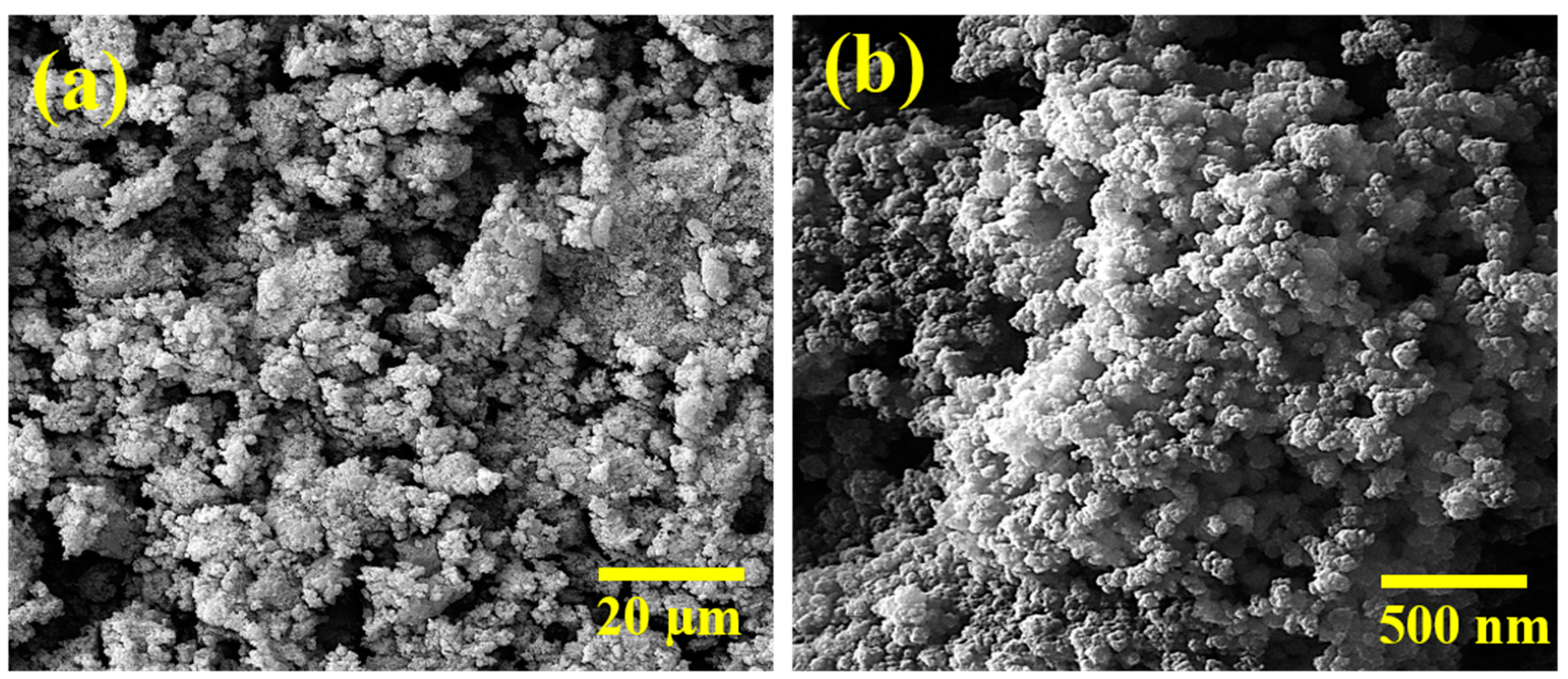
2.3. Synthesis of PPy Nanoparticles (NPs)

Initially, a specific quantity of an anionic surfactant (SDS) was dissolved in 25 mL of distilled water. Subsequently, the pyrrole monomer (1 mmoL) was added to the solution and stirred for 30 min. Thereafter, 25 mL of APS was added dropwise to the reaction mixture with constant stirring at 500 rpm. Eventually, the colorless mixture slowly turned black; the polymerization was stirred at 500 rpm for 24 h at room temperature. After polymerization, the PPy NPs were washed with distilled water several times and dried at 60 °C.

2.4. Preparation of PU/PPy Composite Coatings

To incorporate the synthesized PPy NPs into the PU coatings, different weight ratios of PPy nanoparticles (10, 20, and 30 wt.%) were mixed with the acetone, and the mixture was then probe sonicated for 15 min. The subsequent mixture was probe sonicated with the PU resin for about 15 min and gradually heated to 50 °C while stirring to enable the solvent to evaporate. The PU/PPy mixture was then coated on the SS specimen using the draw-down bar coater with a target thickness of 60 μm, and the wet-coated SS specimens were allowed to cure for about 24 h. Pure PU and PU with the quantity of 10, 20, and 30 wt.% of PPy on the bare and passivated (5.0 V) specimen were represented as PU/Bare, PU/EP5.0V, PU/10PPy, PU/20PPy, and PU/30PPy, respectively.

2.5. Surface and Structural Characterization

The morphology and structure of the passivated surface and coated specimens were analyzed using scanning electron microscopy (SEM), JEOL JSM-6610 LV, which was typically operated at 20 keV accelerating voltage and in secondary electron imaging mode. The topographic characterizations of the passivated surface were examined using an optical profilometer (Bruker Nano GmbH, Contour GT-K, Billerica, MA, USA). The optical profilometer operates based on the principle of interferometrics to provide a three-dimensional topographical image of the specimen by scanning through an area of about 1.66 mm × 2.2 mm (3.5 mm2). Attenuated Total Reflectance-Infrared (ATR-IR) spectral analysis was conducted to elucidate the composition of prepared PU composite coatings in the range of 400–4000 cm−1 using a Thermo scientific spectrometer, with universal ATR attachment with a diamond and ZnSe crystal. A Water Contact Angle (WCA) test was employed using the sessile drop technique to examine the surface hydrophilicity of the coated SS specimens using a WCA instrument (Biolin Scientific, Espoo, Finland). A water droplet (5 µL) was released on the specimen and was instantly photographed. The sessile droplet images were processed by the image analysis system, which calculated the contact angles from the geometry of the droplets after contact with the surface to an accuracy of ±0.1. To achieve an accurate value, ten measurements were collected for each substrate.

2.6. Electrochemical Corrosion Tests

A Gamry (Reference 3000) electrochemical station was utilized to accomplish the electrochemical impedance spectroscopy (EIS), electrochemical frequency measurements (EFM), and potentiodynamic polarization (PDP) tests. The three-electrode cell assembly contained a prepared coated SS specimen as the working electrode, a graphite rod, and a saturated calomel electrode (SCE) as the auxiliary and reference electrode, respectively. Open circuit potential (OCP) was monitored for 1800 s before executing the electrochemical corrosion tests to attain a steady state. The EIS test was performed between the primary frequency of 100 kHz and the ending frequency of 10 m Hz, with a signal amplitude of 10 mV. The PDP test was done at the potential of −0.25 V vs. OCP to 1 V vs. SCE using a scan rate of 0.2 mVs−1. The investigation of PDP and EIS data was executed by the Echem analyst, respectively. The standard deviation values among parallel triplicate experiments were found to be smaller than 5%, demonstrating good reproducibility.

3. Results

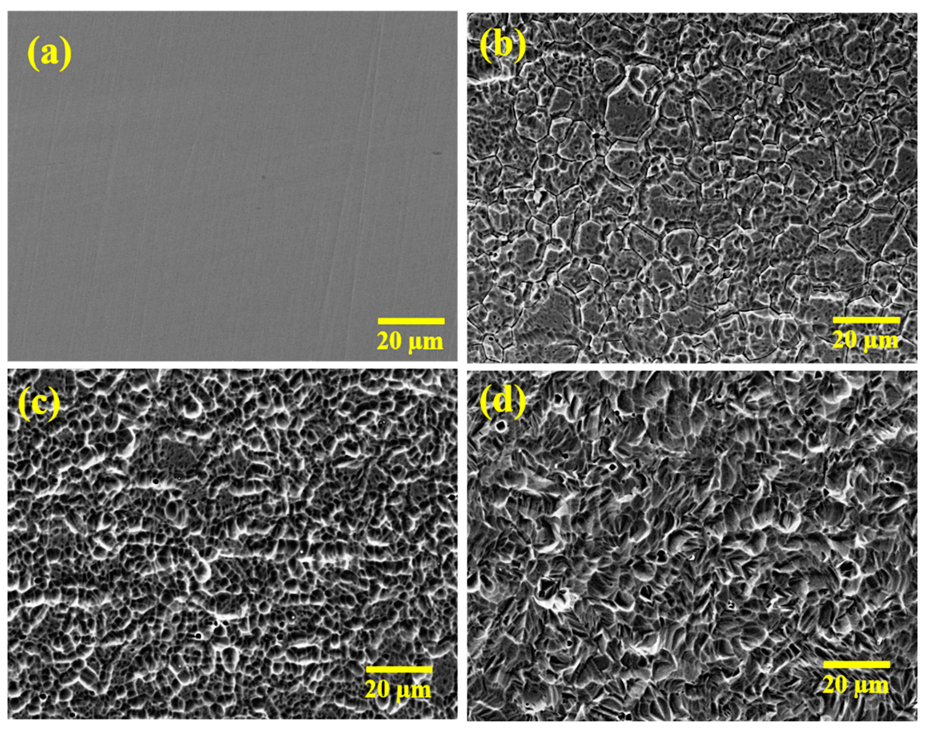
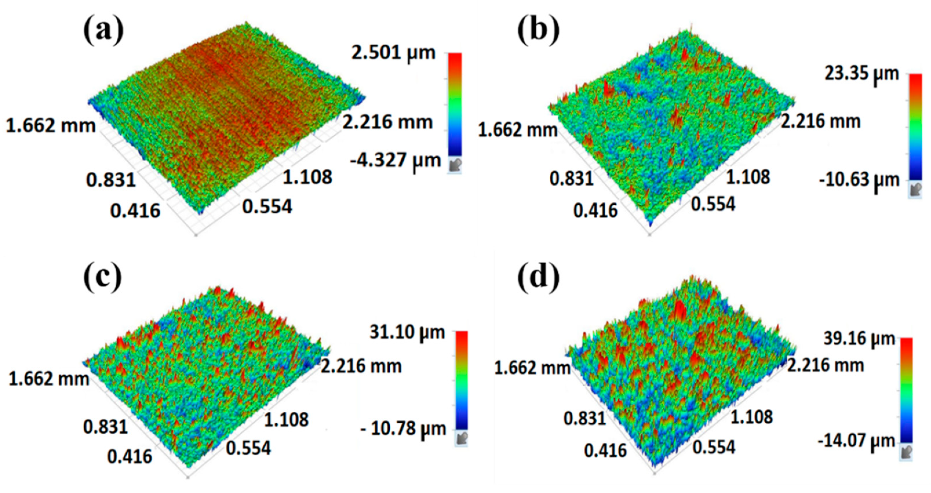
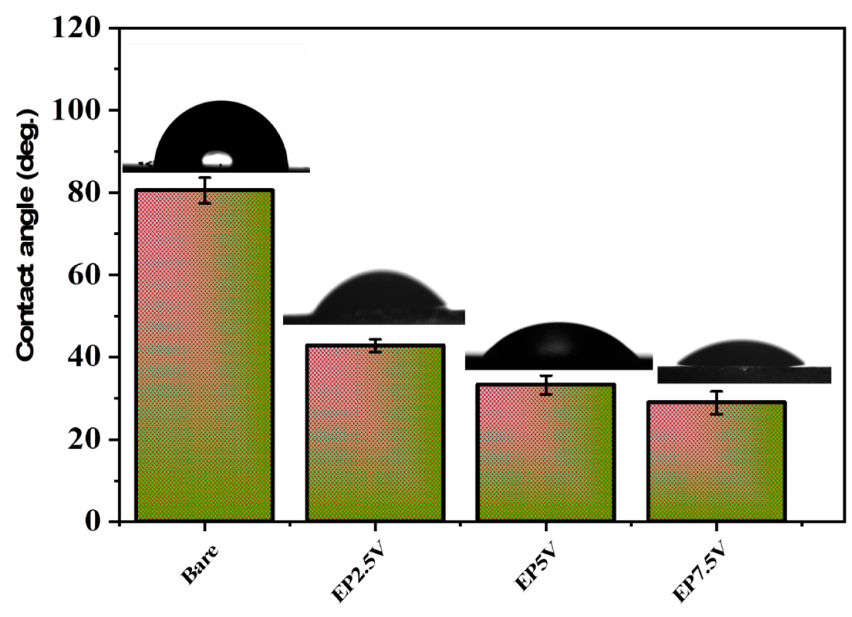
3.1. Characterization of Electrochemically Passivated 316L SS Surface

Surface morphological features of the passivated 316L SS surfaces were analyzed using SEM images shown in Figure 1. The passivated surfaces display a distinctive porous morphology with different pore dimensions, depending on the applied voltage. A compacted surface with smaller pores was observed at 2.5 V (Figure 1b) due to an inadequate voltage applied [13]. However, the passivated surface formed at 5 V (Figure 1c) displayed a uniform distribution of the pores, and their size increased by increasing applied voltage to 7.5 V (Figure 1d). Similarly, the number of pores and craters increased with applied voltage; consequently, the passivated surface became coarser and more heterogeneous at higher applied voltage.
Surface topographical information was observed using the optical profilometric images given in Figure 2. The bare specimen presented a plane surface with a one-directional groove formed during mechanical grinding. In contrast, all the passivated surfaces showed higher surface roughness by displaying abundant asperities, pores, and valleys, owing to the creation of a passive layer with the porous topographic surface as seen in the SEM images in Figure 1. Generally, the surface profile is effectually governed by the variance in the dispersal of asperities, pores, and micro-cracks on the material surface [14]. The surface roughness parameters obtained are shown in Table 2.
The estimation of surface roughness is generally done through the proper selection of different parameters, including the root mean square height of the surface (Rq), maximum height of peaks (Rp), maximum depth of valleys (Rv), ten-point height (Rz), and arithmetic average height of the surface (Ra). Among these, Rq and Ra are the two critical parameters for revealing the surface roughness, as they provide evidence about the probability of deviation from a uniform surface by scanning a constant surface contour [15]. The bare specimen exhibited the lowest Ra and Rq values (Table 2) and increased to about 2.5–6 µm after passivation. The values of Rz are commonly estimated based on the five highest and deepest peaks according to a straight focus contour. Thus, the measurement of Rz provides an indication of the irregularities/heterogeneity on the substrate surface. The results obtained suggest that the passivated specimen at 5.0 V exhibits the lowest Rz value, suggesting the lowest surface heterogeneity. Further, Rv can be used to estimate the pits and cracks on a surface while the Rp can assist in assessing a contaminated surface. By comparing the Rp and Rv values in Table 2, it is observed that the Rp values are steadily higher than the Rv values for all passivated substrates. This specifies that the cause of the roughness is estimated by the Rz value being accompanied by pores, pits, or cracks in the passivated surface. It has been established that the surface with high roughness permits the creation of physical interfaces of the polymeric film with the metallic surface, and thus improves the metal/coating interphase strength through the mechanical interlocking model [16].
Assessing the surface hydrophilicity characteristics is considered the critical elucidation to describe the appropriateness of the material’s surfaces for interrelating with another material [17]. Improvement of the surface chemistry at an interface can effectively modify performance by enhancing interfacial interactions and compatibility with a subsequent polymeric molecule. Frequently, these characteristics can be obtained by tailoring the degree of surface hydrophilicity at an interface. The impact of applied voltage on the surface hydrophilicity of the SS specimens was inspected by monitoring the WCA, and the results are presented in Figure 3. WCA of the bare specimen was found to be 80.50°, revealing a lower surface wettability of the bare SS. The WCA of the SS specimen after electrochemical passivation was sharply decreased to 42.75° (EP2.5V), 33.26° (EP5.0V), and 26.35° (EP7.5V). This validates the improved surface wettability due to the homogeneous surface profile with high surface profile and roughness. Szczepanski et al. [18] emphasized the importance of surface hydrophilicity during the polymer interaction at the interface and reported that the surface hydrophilicity is a critical and necessary design parameter in the field of functional coating materials. The accomplished surface wettability of the SS specimen is anticipated to facilitate improved interaction with the polymeric chain in the subsequent coating process.

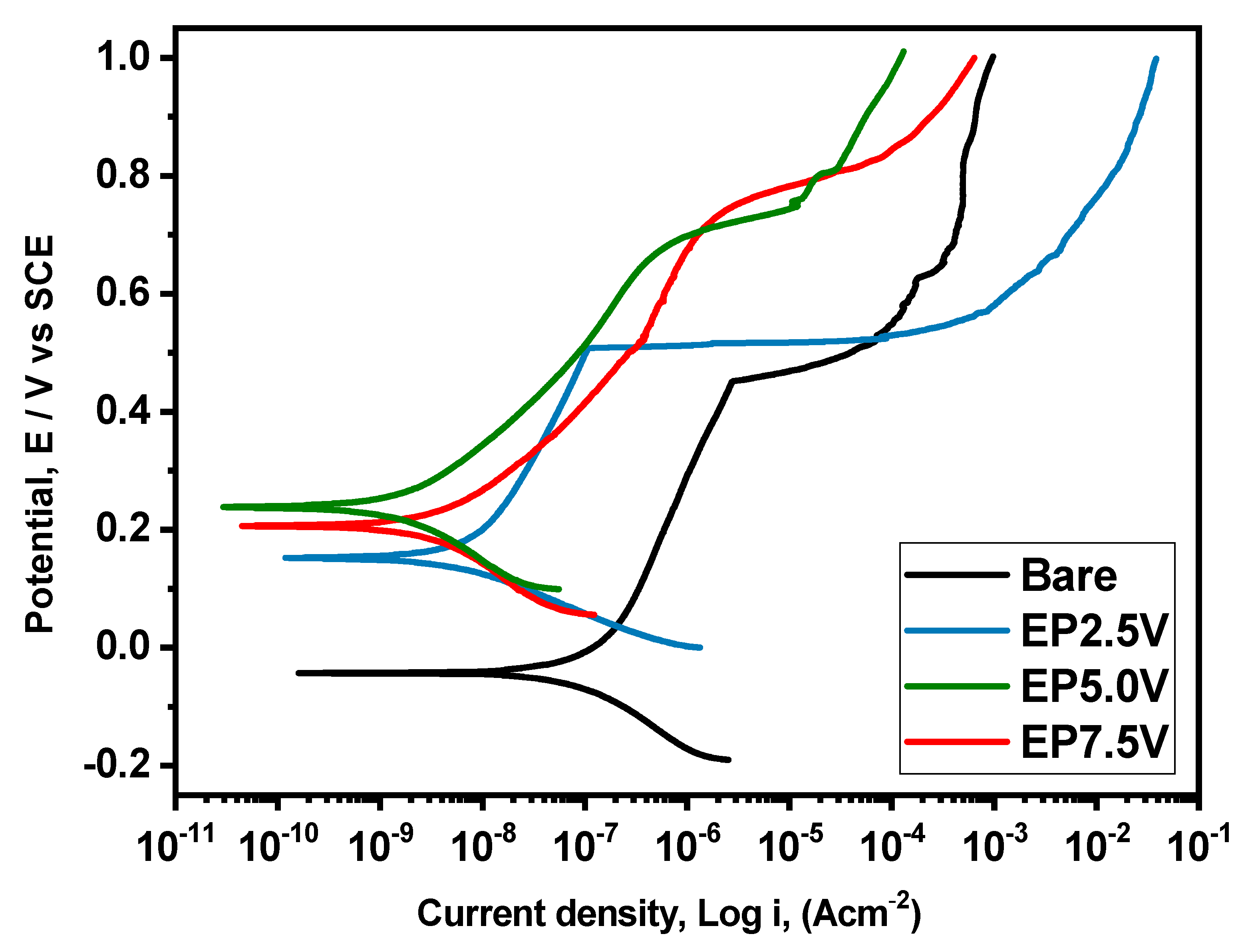
3.2. Corrosion Resistance of Passivated Specimens in NaCl Medium

Primarily, to select the optimized passivated surface for the subsequent coating’s deposition, the corrosion resistance of all the passivated specimens was evaluated in a 3.5% NaCl solution using the PDP tests. The obtained PDP curves are given in Figure 4. The bare specimen presented the highest corrosion current density (icorr) (5.471 × 10⁻⁵ A cm−2) and lowest corrosion potential (Ecorr) (−0.0358 V) values among the examined specimens.
Compared to the bare specimen, the corrosion-resistant behavior of all of the passivated specimens was observed to be improved as specified by the noble shift in Ecorr and a lower icorr. It is well known that the icorr is directly proportional to the rate of corrosion, and a lower icorr value commonly implies a higher corrosion resistance performance [19]. Relating to the bare sample, icorr values of passivated specimens were reduced by more than two orders of magnitude. Amongst the inspected specimens, passivated specimens processed at 5 V revealed the maximum corrosion-resistant performance with an Ecorr of 0.237 V and the lowest icorr of 1.491 × 10⁻⁹ A cm−2. This specifies that the applied voltage of 5 V provided the compact passivated film with more minor micro defects, and therefore improved the barrier features of passivated film on the SS surface. Thus, the passivated specimen processed at an applied voltage of 5 V was selected to proceed further with the deposition of PU composite coatings.

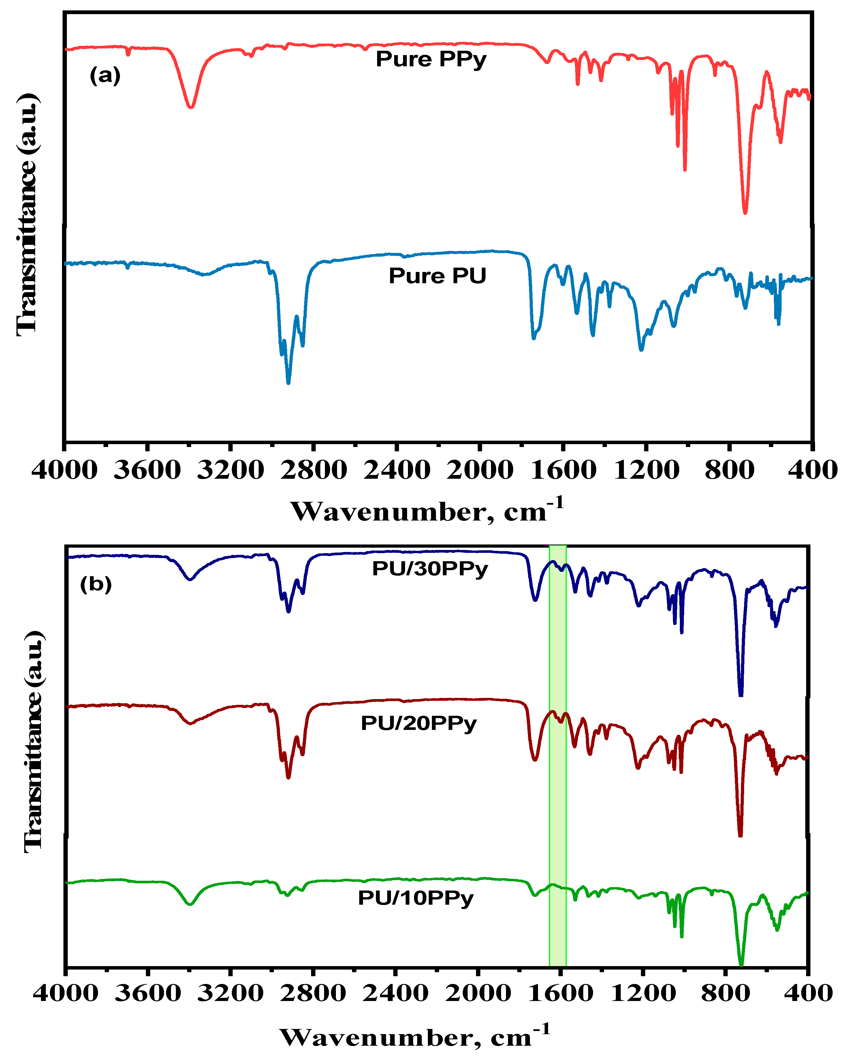
3.3. Structural Characterization of Synthesized PPy Nanoparticles and Hybrid PU/PPy Composite Coatings on Passivated 316L SS

Figure 5 displays the SEM images of PPy nanoparticles. The images reveal that the synthesized PPy particles were spherical, with the size ranging from 50 to 100 nm. Figure 6 presents the IR curves of the synthesized PPy sample and hybrid polymer composite coatings on passivated 316L SS specimens. Synthesized PPy nanoparticles exhibited their distinctive peaks at 3393, 2937, 1674, 1575, 1526, 1143, 1077, 1019, and 718 cm−1, affirming the presence of stretching N–H, intense C–H stretch, C=N, weak C=C, C=C, C–C bonds, =C–H in-plane vibration, =C–H strong bending, and =C–H wagging of the pyrrole moieties, respectively [20].
For pure PU coatings, the peaks obtained at 1737 and 3332 cm−1 authorized the existence of the C=O and N-H groups of polyurethane moieties, respectively [21]. Moreover, the characteristic peaks found at 2850, 1532, and 1211 cm−1 were observed in the investigated coated specimens to corroborate the preparation of polyurethane coatings on 316L SS specimens. In addition, no deceptive change on the PU coated specimens with and without passivated surface corroborated that the PU coatings exhibited a similar chemical structure in both passivated and bare SS specimens. For the prepared PU/PPy composite coatings, the peaks relevant to both PU and PPy were obtained, and the intensity of the peak of the PPy was increased with the quantity of PPy inclusion in the PU composite coatings, further confirming the formation of PU/PPy composite coatings on 316L SS surface. Moreover, an additional peak appeared around 1600 cm−1 in the PU/PPy composite coatings, and its intensity increased with the addition of PPy, which was attributed to the existing hydrogen bonding and interactions between the NH groups and amide carbonyl of Py and PU moieties, as reported in previous research [22].

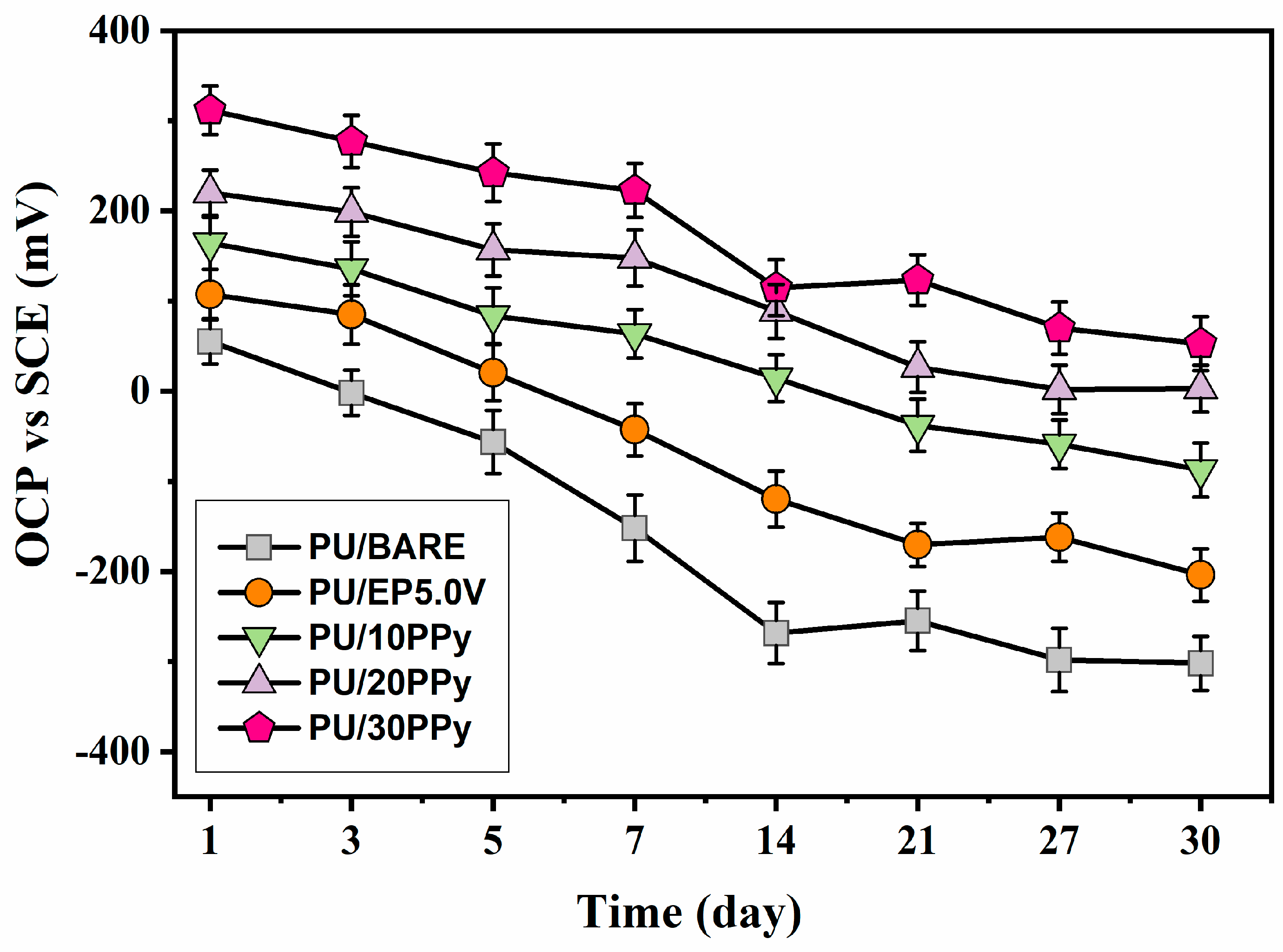
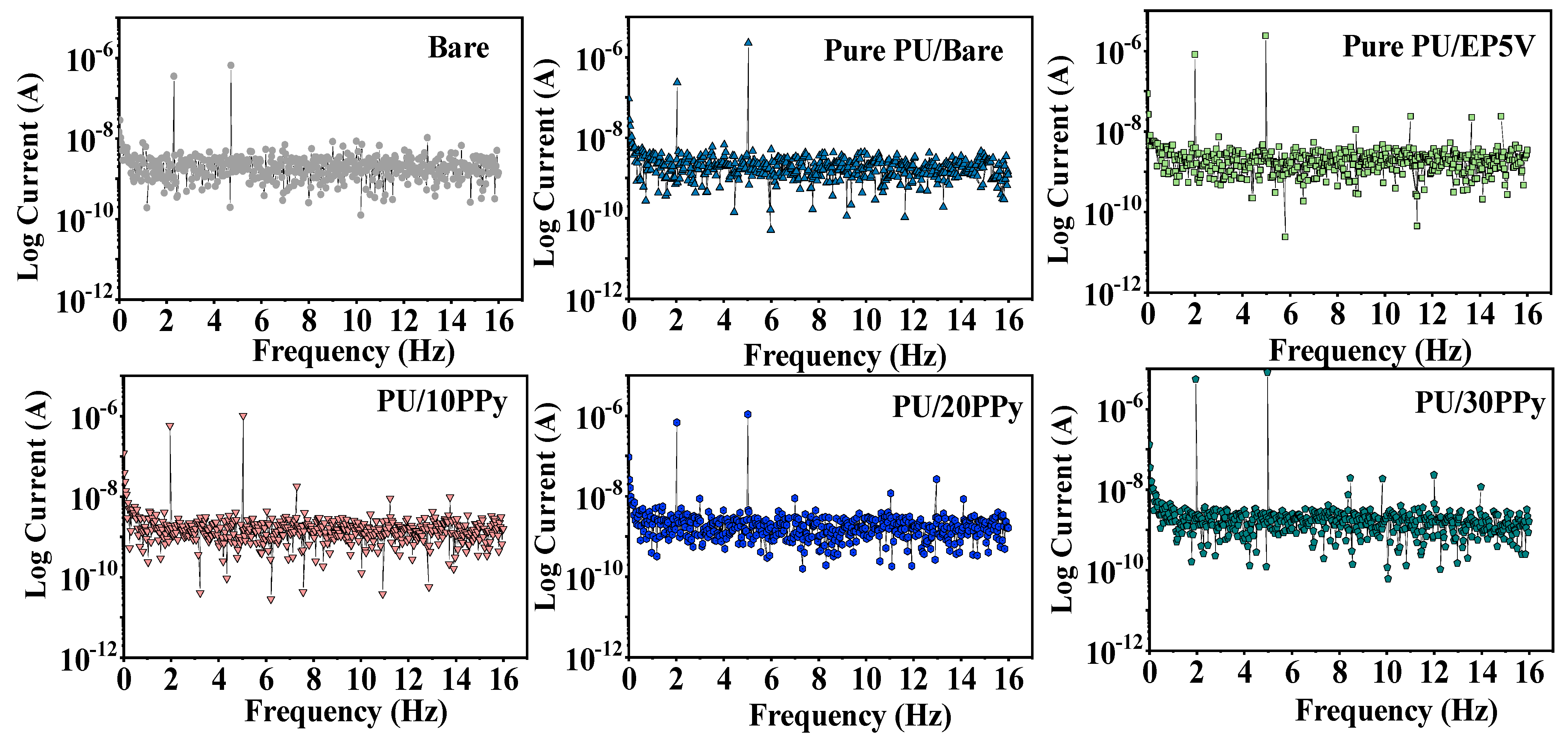
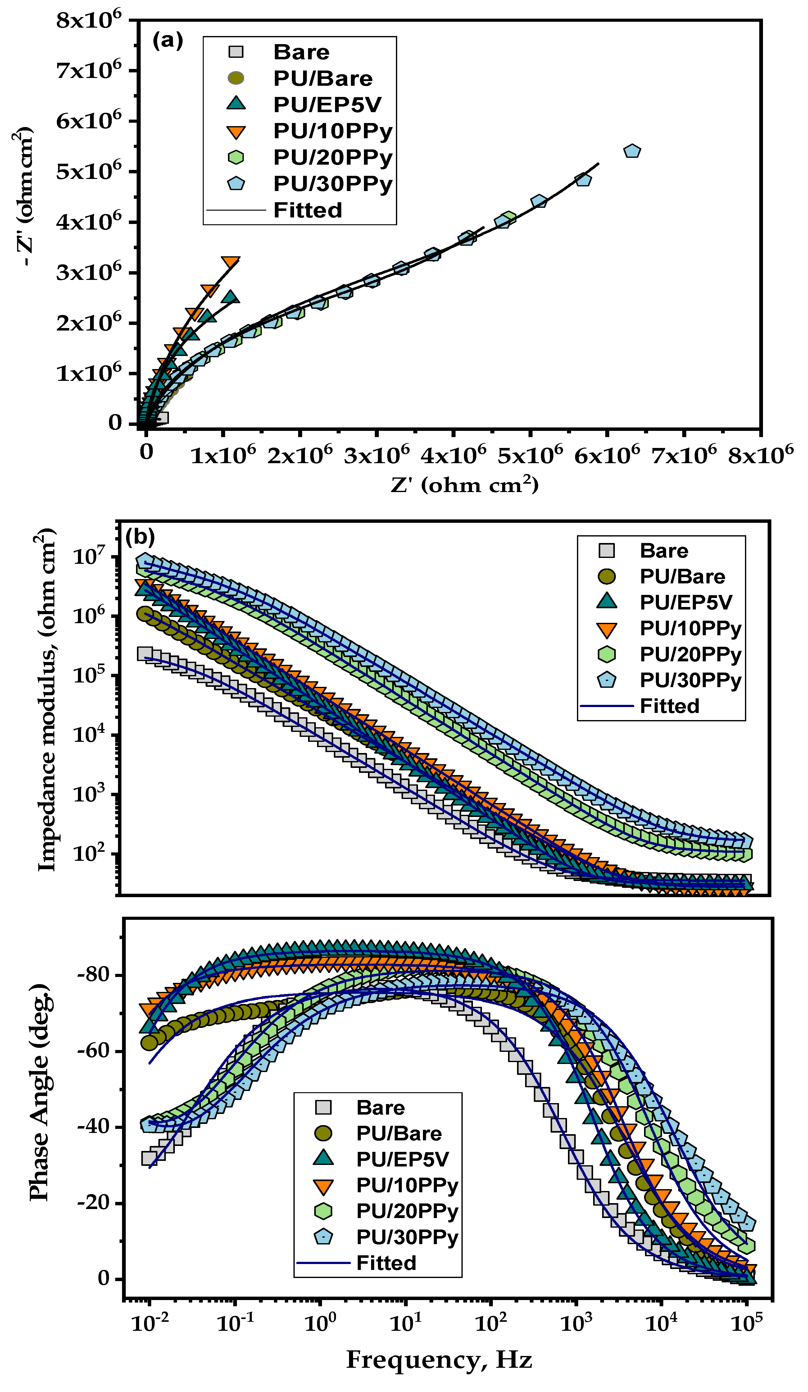
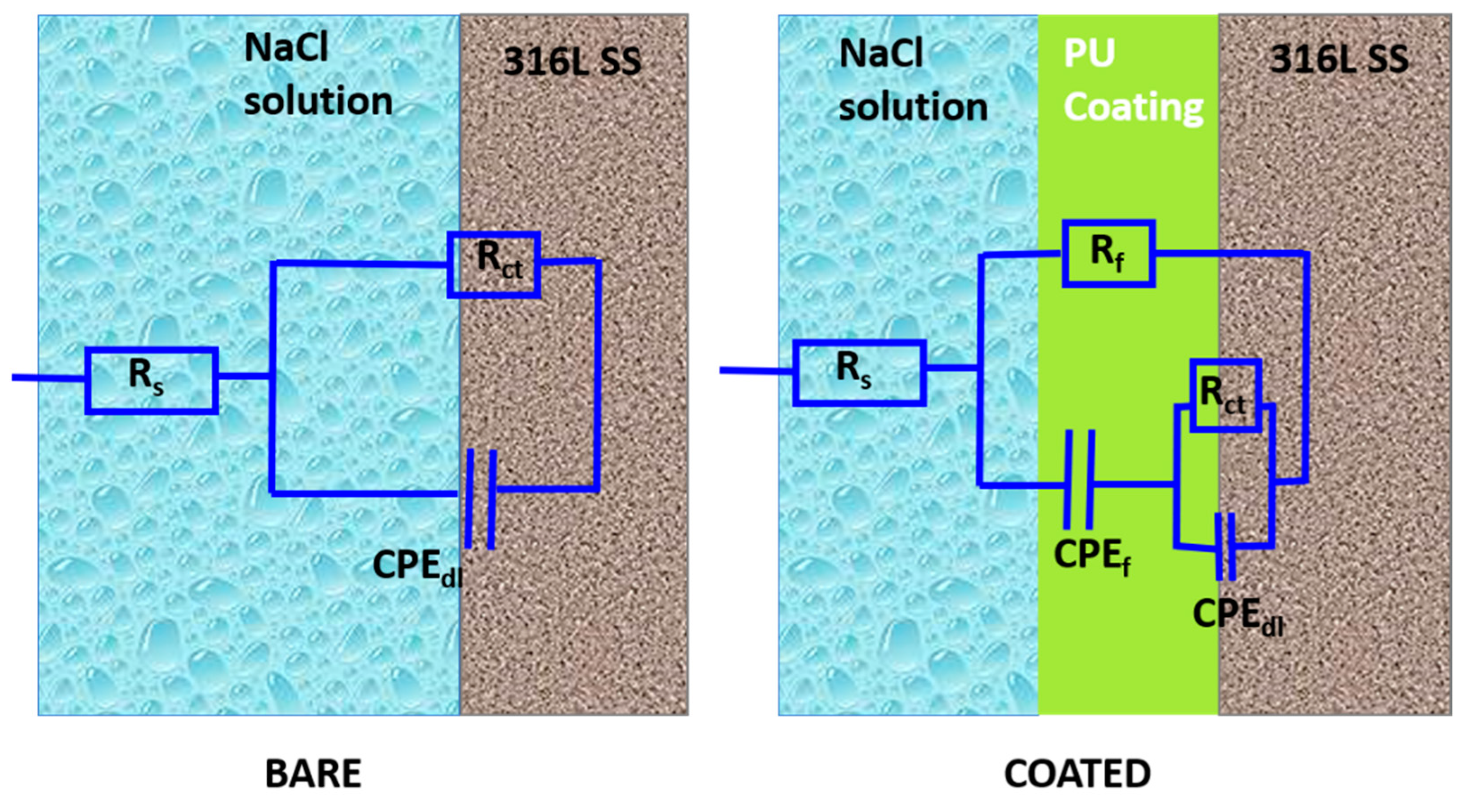
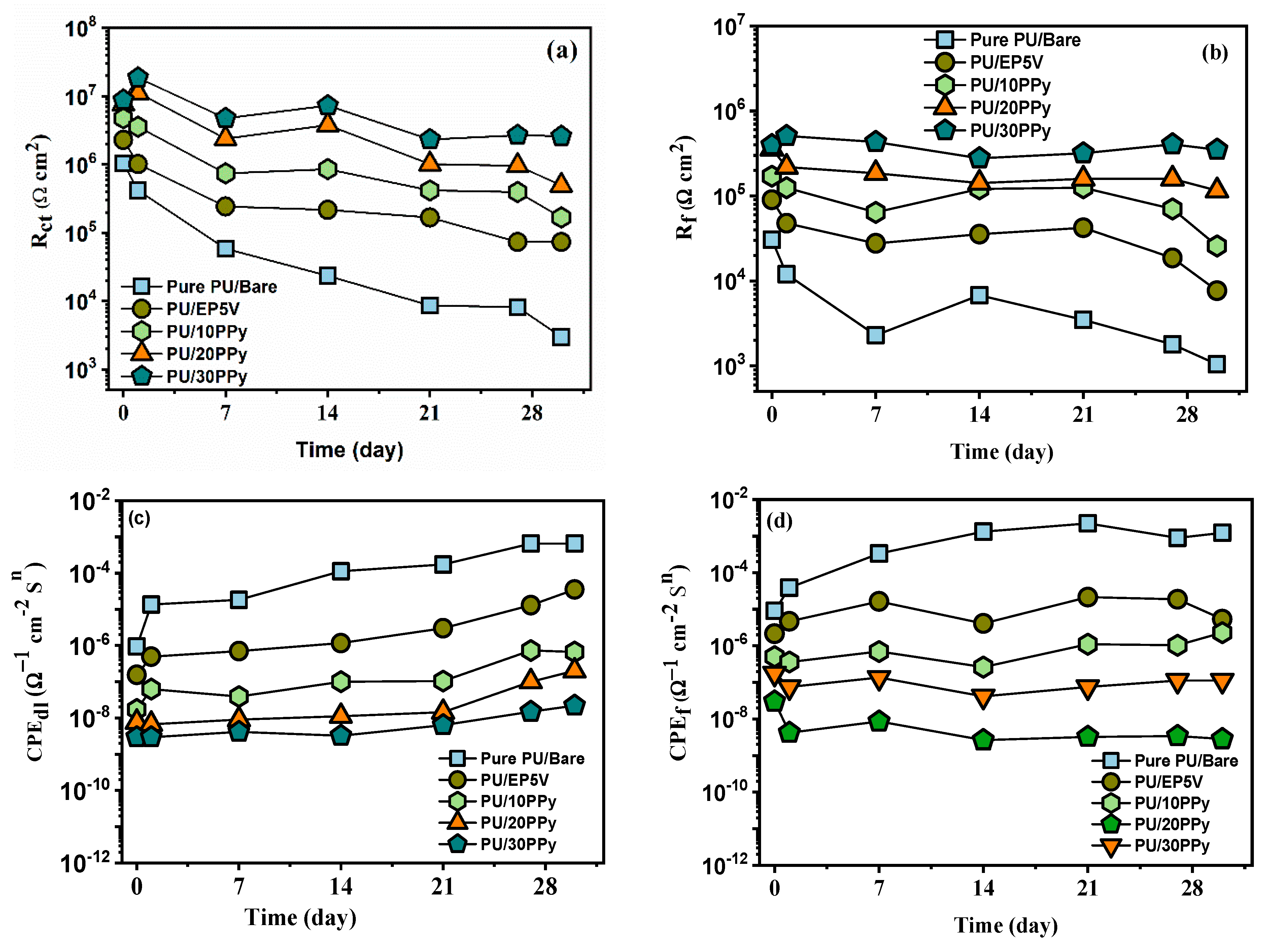
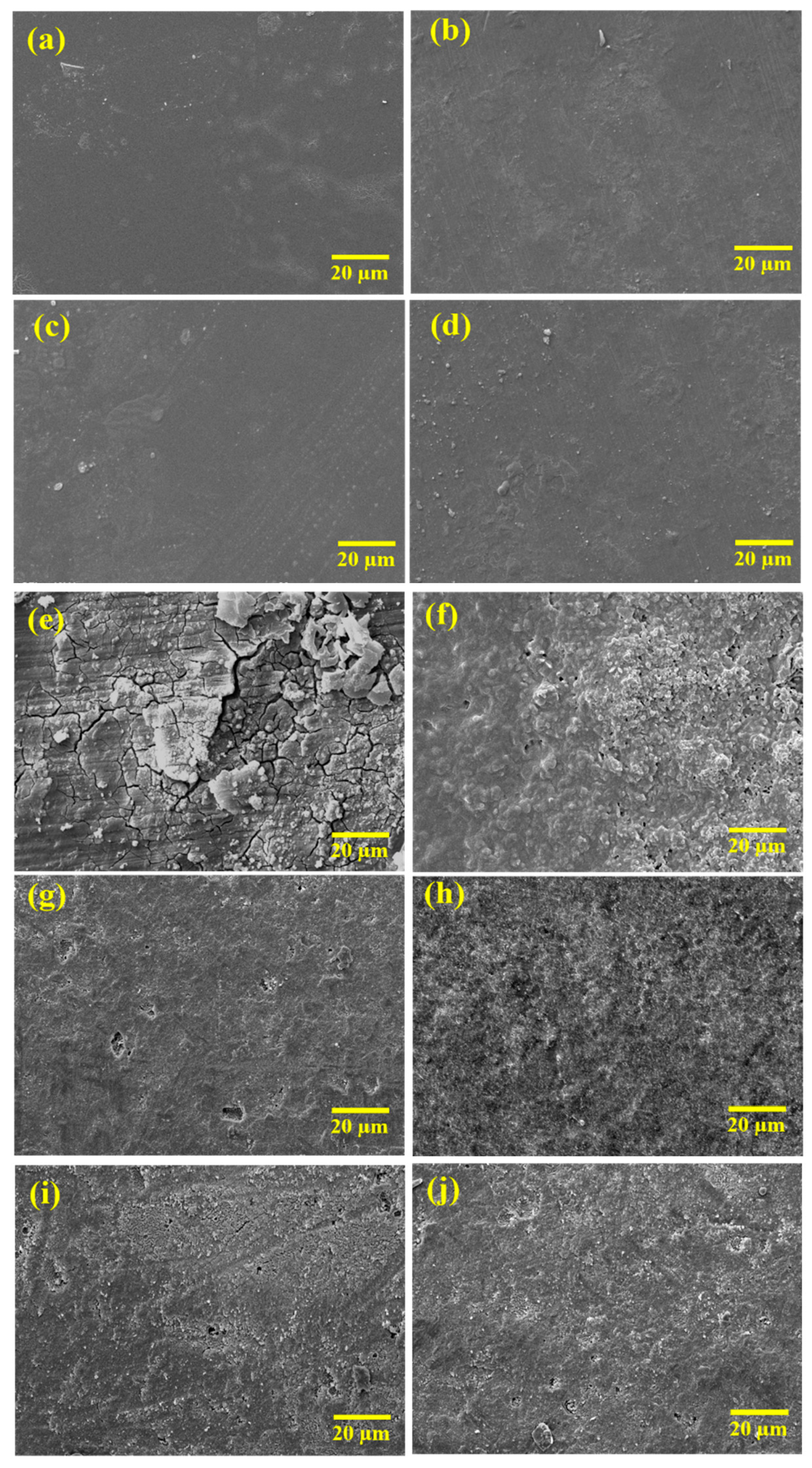
3.4. Corrosion Protection Behavior of PU/PPy Composite Coatings on Passivated SS Surface

Figure 7 displays the monitored OCP values of bare and coated SS specimens for 30 days in a 3.5% NaCl medium to assess the corrosion protection behavior of prepared composite coatings. For bare specimens, OCP values showed prompt decline up to −300 mV in the exposure periods and then gradually attained the constant value after 30 days of exposure. In the case of coated specimens, a minor reduction of the OCP was observed for all the coated specimens ascribed to the penetration of aggressive species through the polymeric film’s micro defects (pores and cracks) to the base substrate [23]. However, in comparison with the base, higher OCP values were shown by all the coated specimens in the first 24 h of exposure. Slight variations were only observed in the remaining immersion period. It is observed from the OCP trend that the resistance to permeation of aggressive species increases from the PU/Bare to PU/30PPy coated samples throughout the 30 days, which reveals the improved protection of the prepared hybrid composite coatings.
Furthermore, PU and PU/PPy coatings on passivated specimens showed the more noble and highly stable values of OCP than the PU on the bare specimen. Notably, the PU/15PPy specimen displayed the highest shift of OCP in a positive direction among the examined specimens. The obtained OCP test results reveal that the passivated layer and the incorporation of PPy could progress the anti-corrosion performance of the PU coatings on SS specimens.
Figure 8 presents the EFM curves of uncoated and coated SS specimens in NaCl, and the estimated parameters are presented in Table 3. The experimentally obtained values were authenticated by comparing the theoretical causality factors, such as CF-2 and CF-3 [24,25]. EFM provides many advantages, including zero sample degradation, greater speed, and the novel capability to intrinsically authenticate the precision of the obtained data by monitoring the parameters such as CF-2 and CF-3. In this investigation, CF-2 and CF-3 values were almost the same as the theoretical values of 2.0 and 3.0, further validating the experimentally acquired values. Compared to the bare specimen, the pure PU and PU/PPy composite coatings showed the Ecorr values of about 100 mV and 150 mV, and the icorr reduced from 0.5471 μA cm−2 to 0.0284 μA cm−2 and 0.0145 μAcm−2, respectively. The notable reduction in icorr and the optimistic change in Ecorr values for the coated specimens corroborate that the prepared composite coatings on passivated specimens provide enhanced corrosion protection in the NaCl medium.
All the coated SS specimens exhibited less icorr than the bare specimen. Most notably, PU/30PPy coatings present the lowest icorr value, implying that the PU composite coating produced on the SS specimen with passivated film and PPy inclusion significantly improves its corrosion resistance performance in a NaCl medium.
To obtain more information on the electrochemical stability of processed PU/PPy coatings on passivated SS specimens, EIS tests were performed over the immersion time of 30 days, and the obtained EIS curves are displayed in Figure 9. The obtained EIS curves for the uncoated specimen showed single-time constant characteristics.
However, the coated SS specimens displayed two time constants: the one at high frequencies associated with the barrier features of the polymeric films and the other relating to the charge transfer reactions at the SS surface under the PU film [26]. Predominant capacitive characteristics were observed for all the examined coated specimens at the investigated frequencies. Furthermore, the impedance value at the low-frequency region was observed to be near 106 Ω cm2, indicating high corrosion resistance due to the strong barrier characteristics of the PU coatings [27]. In particular, the PU/30PPy coated specimens showed a noteworthy rise in the impedance at lower frequencies, most likely due to the construction of compact and defect-free coating films compared with the pure PU coating.
Bode phase angle plots generally provide information on the surface state and structural dissimilarities of the specimens, and the attained phase angle curves demonstrate the capacitive behavior of the inspected frequencies [28]. The shift of the phase angle as a function of frequency for bare and coated specimens is observed to be different, demonstrating that the SS specimens have different corrosion phenomena without and with polymeric films. The diameter of the capacitive arcs in the Nyquist plot reduced with the exposure period, possibly owing to the permeation of electrolytic species into the coating, as all polymeric films are not enduringly impervious due to the micro defects formed during preparation. The impedance values of PU coating at lower frequencies were increased with increasing PPy addition.
Furthermore, equivalent circuit fitting analyses were performed to quantitatively estimate the achieved EIS curves, and the utilized EIS models are shown in Figure 10. Rct, Rf, and Rs designate the charge transfer, film, and electrolytic resistances, respectively. Constant phase element CPEdl (electric double layer capacitance) and CPEf (coating capacitance) were selected to replace capacitance, owing to the surface heterogeneity from ideal capacitance [29,30]. The obtained values for the bare and coated SS specimens are presented in Table 4. Figure 11 displays the obtained EIS parameters as a function of the immersion time. For PU/PPy coatings on passivated specimens, Rct values are higher than the pure PU coatings on bare specimens. The impedance value of the PU/bare SS specimen was significantly decreased after the immersion of 30 days. This result confirmed the beneficial role of both passivated surface and PPy inclusion on the PU coatings.
Moreover, the reduction in the impedance value of the PU/PPy coatings on the passivated surface is found to be lower compared to that of the bare and PU/bare specimens. The reduction in Rct and Rf in the PU/30PPy composite coating was the lowest, indicating that the passivated surface could enhance the interaction between the PU/PPy coating and base SS surface, thereby increasing the barrier features of the PU coating film. In addition, the CPEf and CPEdl values of PU/30PPy coatings were lower than that of pure PU, and the variation in CPEf also exhibits the same trend, corroborating the valuable part of passivation film and the incorporation of PPy moieties into the PU film to expand its anti-corrosion behavior in a NaCl solution.
The surface morphologies of PU/PPy composite coatings on passivated specimens before and after 30 days in a NaCl solution were examined using SEM analysis to attain pictorial evidence of the corrosion reactions occurring at the SS/PU interface. Figure 12a–d presents the PU/PPy composite coating surface on the bare and passivated specimens; the surface of the coatings is featureless and plain without any observable imperfections. Figure 12e–i displays the SEM micrographs of the coated specimens after 30 days of exposure. Beginning with the SEM image of the bare specimen, a severe attack was noticed due to the effective corrosion process. Pure PU coating on the bare specimen presented active corrosion damage as specified by the existence of numerous disseminated locations of corrosion products. The pure PU coating on the passivated surface showed a minor surface corrosion attack, revealing the SS specimen’s inadequate corrosion protection performance. However, PU/PPy composite coatings on passivated specimens showed nearly smooth and fine surfaces free from any obvious corrosion attack, which designates their enhanced corrosion protection performance. The attained SEM images imply that using electrochemical passivation before applying PU coatings, along with the addition of PPy, can increase the anti-corrosion behavior of PU coatings on SS specimens.

4. Conclusions

Surface characterization and corrosion test results of passivated SS specimens validate that the applied voltage of 5 V provides the hydrophilic and uniform porous surface with higher corrosion-resistant performance. PU composite coatings were deposited on passivated SS specimens with the different feed ratios of synthesized PPy particles. Structural characterization reveals the formation of PU/PPy composite coatings and the interaction between the PU and PPy moieties. Corrosion assessment results corroborate that the PU/30PPy coatings provided the Rct value of 1.0869 × 10⁷ Ω cm2, around one order magnitude higher than that of pure PU-A5V (2.726 × 10⁶ Ω cm2). Pure PU/bare (1.101 × 10⁵ Ω cm2), respectively, indicates that the passivated SS specimen with the PU/PPy coating displays the highest surface protection behavior against corrosion. Surface characterization after corrosion tests validates that the corrosion damage is pointedly controlled with the passivation film before coating and the addition of PPy into the PU matrix. The inference from the attained outcomes is that applying the passivation film before PU coating and the incorporation of PPy into PU coating prominently enhances the barrier features and anti-corrosion performance of SS specimens in a NaCl solution.

Author Contributions

Conceptualization, A.M.K. and J.S.N.R.; methodology, A.M.K., A.Y.A., M.M.R. and J.V.; validation and formal analysis, A.M.K., J.S.N.R. and A.Y.A.; investigation, A.M.K., M.M.R. and J.V.; data curation, A.M.K. and J.V.; writing—original draft preparation, A.M.K. and J.V.; writing—review and editing, A.M.K., A.Y.A., M.M.R. and J.S.N.R. All authors have read and agreed to the published version of the manuscript.

Funding

This research received no external funding.

Data Availability Statement

The data presented in this study are part of a Ph.D. research and are available on request from the corresponding author until the dissertation is made public. Afterward, the data will be available in a publicly accessible repository.

Acknowledgments

The authors gratefully acknowledge King Fahd University of Petroleum and Minerals (KFUPM) for providing the facilities for the research.

Conflicts of Interest

The authors declare no conflict of interest.

References

  1. Tao, X.P.; Zhang, S.; Zhang, C.H.; Wu, C.L.; Chen, J.A.O. Effect of Fe and Ni contents on microstructure and wear resistance of aluminum bronze coatings on 316 stainless steel by laser cladding. Surf. Coat. Technol. 2018, 342, 76–84. [Google Scholar] [CrossRef]
  2. Naiming, L.; Luxia, Z.; Jiaojuan, Z.; Qiang, L.; Shuo, Y.; Lulu, Z.; Yuan, Y.; Zhiqi, L.; Qunfeng, Z.; Xiaoping, L.; et al. A combined surface treatment of surface texturing-double glow plasma surface titanizing on AISI 316 stainless steel to combat surface damage: Comparative appraisals of corrosion resistance and wear resistance. Appl. Surf. Sci. 2019, 493, 747–765. [Google Scholar]
  3. Hong, H.G.; Guo, D.Z.; Wen, Q.W. Passivation model of 316 stainless steel in simulated cooling water and the effect of sulfide on the passive film. Appli. Surf. Sci. 2003, 211, 321–334. [Google Scholar]
  4. Lei, G.; Jianhong, T.; Savas, K.; Senlin, L.; Li, Q.; Fan, Z. Multidimensional insights into the corrosion inhibition of 3,3-dithiodipropionic acid on Q235 steel in H2SO4 medium: A combined experimental and in silico investigation. J. Coll. Interf. Sci. 2020, 570, 116–124. [Google Scholar]
  5. Bochuan, T.; Wei, L.; Shengtao, Z.; Hongda, D.; Yujie, Q.; Anqing, F.; Yun, R.; Junle, X.; Riadh, M.; Wenpo, L. Passiflora edulia Sims leaves Extract as renewable and degradable inhibitor for copper in sulfuric acid solution. Coll. Sur. A Phy. Eng. Asp. 2022, 645, 128892. [Google Scholar]
  6. Abdollahi, H.; Ershad-langroudi, A.; Salimi, A.; Rahimi, A. Anticorrosive coatings prepared using epoxy-silica hybrid nanocomposite materials. Corros. Sci. 2014, 123, 21–26. [Google Scholar] [CrossRef]
  7. Wei, H.; Ding, D.; Wei, S.; Guo, Z. Anticorrosive conductive polyurethane multiwalled carbon nanotube nanocomposites. J. Mater. Chem. A 2013, 1, 10805–10813. [Google Scholar] [CrossRef]
  8. Mohammad, M.R.; Hasan, M.Z.; Bashirul, M.H.; Dhafer, A.; Al Shehri, A.; Kumar, M. Corrosion Inhibition Properties of Waterborne Polyurethane/ Cerium Nitrate Coatings on Mild Steel. Coatings 2018, 8, 34. [Google Scholar]
  9. Farshchi, N.; Gedan-Smolka, M. Polyurethane Powder Coatings: A Review of Composition and Characterization. Ind. Eng. Chem. Res. 2020, 34, 15121–15132. [Google Scholar] [CrossRef]
  10. Ates, M. A review on conducting polymer coatings for corrosion protection. J. Adh. Sci. Technol. 2016, 30, 510–1536. [Google Scholar] [CrossRef]
  11. Deshpande, P.P.; Jadhav, N.G.; Gelling, V.J.; Sazou, D. Conducting polymers for corrosion protection: A review. J. Coat. Technol. Res. 2014, 11, 473–494. [Google Scholar] [CrossRef]
  12. Zadeha, M.K.; Yeganeha, M.; Shoushtaria, M.T.; Khanian, A.E. Corrosion performance of polypyrrole-coated metals: A review of perspectives and recent advances. Syn. Met. 2021, 274, 116723. [Google Scholar] [CrossRef]
  13. Jothi, V.; Adesina, A.Y.; Kumar, A.M.; Rahman, M.M.; Nirmal Ram, J.S. Influence of an anodized layer on the adhesion and surface protective performance of organic coatings on AA2024 aerospace Al alloy. Prog. Org. Coat. 2020, 138, 05396. [Google Scholar] [CrossRef]
  14. Jothi, V.; Adesina, A.Y.; Kumar, A.M.; Rahman, M.M.; Nirmal Ram, J.S. Enhancing the biodegradability and surface protective performance of AZ31 Mg alloy using polypyrrole/gelatin composite coatings with anodized Mg surface. Surf. Coat. Technol. 2020, 381, 125139. [Google Scholar] [CrossRef]
  15. Kumar, A.M.; Hussein, M.A.; Adesina, A.Y.; Ramakrishna, S.; Al-Aqeeli, N. Influence of surface treatment on PEDOT coatings: Surface and electrochemical corrosion aspects of newly developed Ti alloy. RSC Adv. 2018, 8, 9181–19195. [Google Scholar]
  16. Laouamri, H.; Giljean, S.; Arnold, G.; Kolli, M.; Bouaouadja, N.; Tuilier, M.H. Roughness influence on the optical properties and scratch behavior of acrylic coating deposited on sandblasted glass. Prog. Org. Coat. 2016, 101, 400–406. [Google Scholar] [CrossRef]
  17. Jothi, V.; Adesina, A.Y.; Rahman, M.M.; Madhan Kumar, A.; Nirmal Ram, J.S. Improved Adhesion and Corrosion Resistant Performance of Polyurethane Coatings on Anodized Mg Alloy for Aerospace Applications. J. Mater. Eng. Perform. 2020, 29, 2586–2596. [Google Scholar] [CrossRef]
  18. Szczepanski, C.R.; Torkelson, J.M. Engineering Surface Hydrophilicity via Polymer Chain-End Segregation in Coatings Formed by Photopolymerization. ACS Appl. Polym. Mater. 2019, 1, 3095–3102. [Google Scholar] [CrossRef]
  19. Jothi, V.; Akeem Yusuf Adesina, M.K.; Nirmal Ram, J.S. Influence of Organic Acids on the Surface and Corrosion Resistant Behavior of Anodized Films on AA2024 Aerospace Alloys in Artificial Seawater. Met. Mater. Inter. 2020, 26, 1611–1620. [Google Scholar] [CrossRef]
  20. Herrasti, P.; Dıaz, L.; Ocon, P.; Ibanez, A.; Fatas, E. Electrochemical and mechanical properties of polypyrrole coatings on steel. Electrochim. Acta 2004, 49, 3693–3709. [Google Scholar] [CrossRef]
  21. Madhan Kumar, A.; Mizanur Rahman, M.; Zuhair Gasem, M. A promising nanocomposite from CNTs and nanoceria: Nanostructured fillers in polyurethane coatings for surface protection. RSC Adv. 2015, 5, 63537–63544. [Google Scholar] [CrossRef]
  22. Yanilmaz, M.; Kalaoglu, F.; Karakas, H.; Sarac, S. Preparation and Characterization of Electrospun Polyurethane–Polypyrrole Nanofibers and Films. J. Appl. Polym. Sci. 2012, 125, 4100–4108. [Google Scholar] [CrossRef]
  23. Madhan Kumar, A.; Khan, A.; Suleiman, R.; Qamar, M.; Saravanan, S.; Dafalla, H. Bifunctional CuO/TiO2 nanocomposite as nanofiller for improved corrosion resistance and antibacterial protection. Prog. Org. Coat. 2018, 114, 9–18. [Google Scholar] [CrossRef]
  24. Obot, I.B.; Ikenna, B. Electrochemical frequency modulation (EFM) technique: Theory and recent practical applications in corrosion research. J. Mol. Liq. 2018, 249, 83–96. [Google Scholar] [CrossRef]
  25. Khaled, K.F. Electrochemical evaluation of environmentally friendly cerium salt as corrosion inhibitor for steel in 3.5% NaCl. Inter. J. Electrochem. Sci. 2013, 8, 3974–3987. [Google Scholar]
  26. Adesina, A.Y.; Gasem, Z.M.; Kumar, A.M. Corrosion Resistance Behavior of Single-Layer Cathodic Arc PVD Nitride-Base Coatings in 1M HCl and 3.5 pct NaCl Solutions. Metall. Mater. Trans. B 2017, 36, 1322. [Google Scholar] [CrossRef]
  27. Christopher, G.; Kulandainathan, M.A.; Harichandran, G. Comparative study of effect of corrosion on mild steel with waterborne polyurethane dispersion containing graphene oxide versus carbon black nanocomposites. Prog. Org. Coat. 2015, 89, 199–211. [Google Scholar] [CrossRef]
  28. Madhan Kumar, A.; Khan, A.; Khan, M.Y.; Suleiman, R.; Jose, J.; Dafalla, H. Hierarchical graphitic carbon nitride-ZnO nanocomposite: Viable reinforcement for the improved corrosion resistant behavior of organic coatings. Mater. Chem. Phy. 2020, 251, 122987. [Google Scholar] [CrossRef]
  29. Pawar, P.G.; Xing, R.; Kambale, R.C.; Kumar, A.M.; Liu, S.; Latthe, S.S. Polystyrene assisted superhydrophobic silica coatings with surface protection and self-cleaning approach. Prog. Org. Coat. 2017, 105, 235–244. [Google Scholar] [CrossRef]
  30. Madhan Kumar, A.; Sanjay Latthe, S.; Sudhagar, P.; Obot, I.B.; Zuhair Gasem, M. Insitu synthesis of hydrophobic SiO2-PMMA composite for surface protective coatings: Experimental and quantum chemical analysis. Polymers 2015, 77, 79–86. [Google Scholar] [CrossRef]
Figure 1. SEM images of untreated and treated 316L SS specimens (a) Bare, (b) EP2.5V, (c) EP5.0V, and (d) EP7.5V.
Cmd 03 00033 g001
Figure 2. Surface topographic images of untreated and treated 316L SS specimens (a) Bare, (b) EP2.5V, (c) EP5.0V, and (d) EP7.5V.
Cmd 03 00033 g002
Figure 3. WCA results of untreated and treated 316L SS specimens.
Cmd 03 00033 g003
Figure 4. PDP curves of untreated and treated 316L SS specimens.
Cmd 03 00033 g004
Figure 5. SEM images of synthesized PPy nanoparticles (a,b) in different magnification.
Cmd 03 00033 g005
Figure 6. IR curves of prepared (a) pure PU, Pure PPy and (b) its composite coatings.
Cmd 03 00033 g006
Figure 7. OCP values of prepared coatings on passivated and bare specimens in a 3.5% NaCl solution in different immersion periods (error bars represent the standard deviation of triplicates).
Cmd 03 00033 g007
Figure 8. EFM curves of prepared coatings on passivated and bare specimens in a 3.5% NaCl solution.
Cmd 03 00033 g008
Figure 9. (a) Nyquist plots; (b) Bode plots of prepared coatings on passivated and bare specimens in a 3.5% NaCl solution.
Cmd 03 00033 g009
Figure 10. EIS circuit models for the bare and coated specimens.
Cmd 03 00033 g010
Figure 11. EIS circuit parameters for the prepared coatings on passivated and bare specimens in a 3.5% NaCl solution in different immersion periods (a) Rct, (b) Rf, (c) CPEdl, and (d) CPEf.
Cmd 03 00033 g011
Figure 12. SEM images of prepared coatings (a) PU/EP5V, (b) PU/10PPy, (c) PU/20PPy, (d) PU/30PPy, and (e) bare, (f) PU/Bare, (g) PPy/EP5V, (h) PU/10PPy, (i) PU/20PPy, (j) PU/30PPy after immersion in 3.5% NaCl solution.
Cmd 03 00033 g012
Table 1. Composition of utilized 316L SS specimens.
AlloyMain Alloying Elements (wt.%)
CrNiMoNCMnFe
316L SS17.2012.602.400.020.031.95balance
Table 2. Surface topographic and roughness parameters for the untreated and treated 316L SS specimens.
SubstratesRa (µm)Rp (µm)Rq (µm)Rz (µm)Rv (µm)
Bare0.2894.4930.38513.541−9.074
EP2.5V2.79375.2794.43185.722−10.443
EP5.0V4.22536.8185.51350.683−13.866
EP7.5V4.92147.6025.97469.447−21.845
Table 3. EFM parameters of uncoated and coated 316L SS specimens in a 3.5% NaCl solution.
S. NoSubstratesEcorr
V
icorr
µA cm−2
CF2CF3
1Bare −0.03580.54711.892.91
2PU/Bare0.05520.04551.872.89
3PU/EP5.0V0.10750.02841.882.90
4PU/10PPy0.16430.01451.902.89
5PU/20PPy0.22470.00841.872.88
6PU/30PPy0.31170.00471.912.92
Table 4. EIS parameters of uncoated and coated 316L SS specimens in 3.5% NaCl solution.
SubstrateRs
Ω cm2
Rct
kΩ cm2
Qdl
Ω−1·cm−2·sn × 10−9
ndlRf
kΩ cm2
Qf
Ω−1·cm−2·sn × 10−9
nf
Bare45.58201.3325.250.95------------
PU/Bare48.321105.216.250.9611.9515.250.94
PU/EP5.0V46.542726.001.080.9614.568.560.95
PU/10PPy44.983452.250.850.9729.841.250.96
PU/20PPy43.579122.570.640.96121.580.820.94
PU/30PPy41.2510,8690.120.97225.840.710.95
Publisher’s Note: MDPI stays neutral with regard to jurisdictional claims in published maps and institutional affiliations.

