1. Introduction
Prevention of steel reinforcement corrosion and the rehabilitation of affected structures has been a key area of research over the years. Corrosion-related refurbishment work in reinforced concrete structures such as roads, bridges, marine structures, industrial buildings, and commercial and residential buildings accounts for a significant share of the total direct cost of corrosion. The indirect cost of corrosion damage to the public is difficult to estimate, but based on a life-cycle analysis of corrosion maintenance, repair, and rehabilitation for bridges in the United States, the cost in terms of lost productivity, traffic delays, etc., could be as high as the direct costs [
1].
On the other hand, awareness of durability and sustainability have been of great importance in the promotion of inspection and monitoring campaigns, in which evaluation of corrosion is becoming increasingly important. An easy way to detect and prevent corrosion before any visible damage has appeared can be by the application of some electrochemical methods such as polarization resistance in the onsite inspection of corrosion in reinforced concrete [
2].
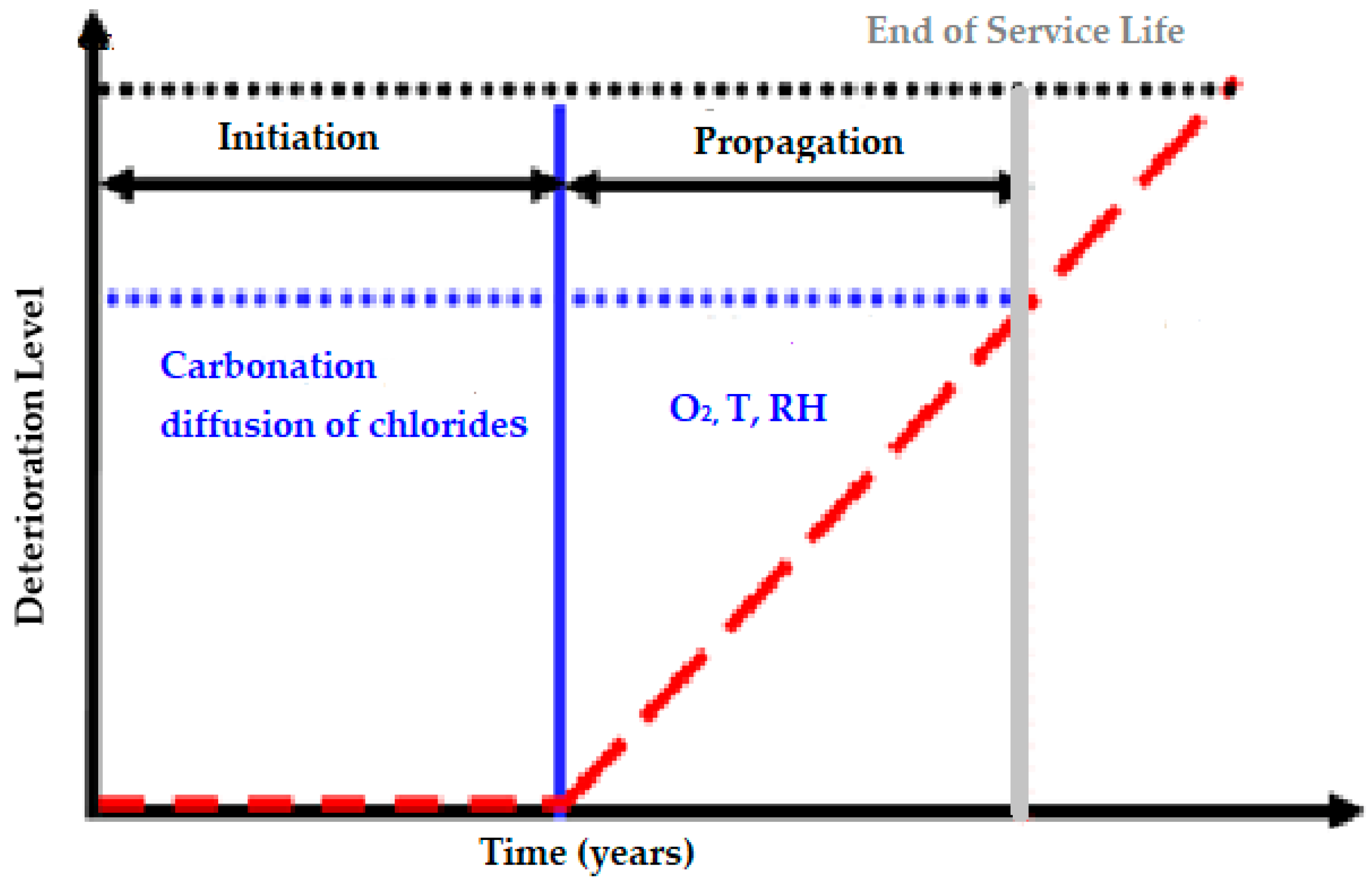
Service life and durability can be defined as the period during which the structure has all of its serviceability, and it works properly in its functionality, resistance, security and external aspect. If we consider Tuuti’s model, we can observe in a schematic mode how the damages evolve in kinetic terms in
Figure 1 [
3].
Degradation processes in reinforced concrete structures affect durability and are partially controlled by the transport of aggressive ions through the concrete microstructure. Ions are charged, and the ability of concrete to resist the transfer of ions greatly relies on its electrical resistivity. Hence, a connection exists between the electrical resistivity of concrete and the deterioration processes such as an increase in permeability and corrosion of embedded steel. Consequently, the transport of ions through the microstructure of concrete plays an important role in the control of concrete durability, especially when cracks appear. After cracking, high permeability results from a network with more connectivity and eventually leads to lower electrical resistivity measurements. In this case, the effect of the dual-phase inhibitor that remains latent is necessary in order to recover the active protection, is not only in the internal protection of the rebar but also on the cementitious matrix of the concrete.
1.1. Deterioration of Structures Exposed to Chlorides
Chloride ions can be introduced to the concrete in several ways: admixtures, contaminated aggregates, mix water, salt water and de-icing salts. While carbonation decreases the pH in the concrete, chloride ions promote the breakdown of the passive film that is formed due to the highly alkaline pH of concrete on the reinforcing steel, and the initiation of localized corrosion at the steel surface. In a chloride attack, chloride ions are diffused through the concrete to the steel. This disrupts the passive layer at a localized place on the rebar and leads to corrosion. In addition, carbonation also results in the breakdown of the passive layer and furthermore increases the free chlorides by releasing the bound ones [
4]. The critical chloride concentration or threshold depends on the type and size of pores and the interconnection between them, oxygen content near the rebars (therefore indirectly by cracks presence, extension and width), and by the type of cement and pozzolanic additions used in the mixture and the water/cementitious material ratio (w/cm) ratio and the nature of the cation associated with the chloride ion.
This chloride-induced corrosion process, which is considered one of the primary causes of degradation of reinforced concrete structures, can cause reduction of the cross-sectional area of the reinforcing steel and formation of voluminous corrosion products that can induce cracking and spalling of the concrete structure [
5].
Steel reinforcement corrosion in a chloride environment starts with the local destruction of the passivating film on steel. This creates an electrochemical microcell, in which the depassivated area acts as the anode (eventually giving rise to the formation of a corrosion pit), and the surrounding film-sound areas act as the cathode. Furthermore, an electrical circuit is generated starting from the reinforcing bar and the enclosing concrete cover. Such a circuit ensures that the current flow attracts chloride ions towards the pit formation area, increasing their aggressiveness in the anode. At the same time, the hydrolysis of the soluble corrosion products (iron ions) occurs, which generates a local decrease in alkalinity, also increasing the steel corrosion rate.
The passage of current generates a second effect in which the oxide film surrounding the pit stabilizes due to the removal of the chloride ions and to the reduction of oxygen, which increases the alkalinity. This phenomenon does not allow the pit to expand laterally, which forces the pit to progress aggressively in depth with a speed on the order of a millimeter per year.
Chloride ions’ ingress from the service environment, however, can only be avoided by using good-quality concrete, sufficient cover depth or applying a surface material/substance to the concrete that can act as an effective barrier. Different surface treatments can be applied to reinforced concrete elements in order to prevent the corrosion or to rehabilitate corroding structures. These treatments may aim to reduce the ingress of oxygen, moisture or chlorides, or to increase the electrical resistivity of concrete.
1.2. Corrosion Inhibitors in Repair and Refurbishment of Reinforced Concrete
According to the International Standard Organizations (ISO) 8044:2015 standard [
6], a corrosion inhibitor is defined as a “chemical substance which decreases the corrosion rate when present in the corrosion system at a suitable concentration, without significantly changing the concentration of any other corrosive agent”. This last point significantly implies the exclusion of other corrosion protection techniques such as coatings, sealers, pore blockers, pore liners and other materials which are able to change the pH, water, oxygen, and chloride concentrations, from the definition of corrosion inhibitors [
7,
8]. However, a secondary property of some inhibitors is that they can also behave as sealers [
8].
The best-known surface-applied corrosion inhibitors (SACI) or migrating corrosion inhibitors are based on an inhibiting compound that diffuses through the concrete pores and reaches the steel rebar to protect steel against corrosion through the formation of a passive layer. This type of inhibitor is relatively economical and easy to apply [
9]. Sodium monofluorophosphate, alkanolalamines and aminoalcohol-based corrosion inhibitors are classified as SACI because they can diffuse through the concrete pores to reach the surface of steel rebar [
10,
11,
12,
13,
14,
15,
16,
17]. However, the efficiency of these inhibitors on reinforced concrete is limited under certain conditions. For instance, monofluorophosphate shows very little effectiveness on the corrosion rates of steel in both non-carbonated and carbonated concretes [
14,
17]. Several experimental studies and field surveys have revealed that the amine-based inhibitors (aminoalcohols and aminocarboxylates) also have very limited impact on inhibiting ongoing corrosion [
18,
19,
20,
21].
On the other hand, surface-applied silanes are used as an effective method for increasing concrete resistivity because of their production of hydrophobicity on concrete surfaces [
22].
In light of this fact, various types of surface-applied corrosion inhibitors (SACIs) have been developed over the past decades to stop ongoing corrosion processes in old concrete. The difference is that this kind of SACI only provides a corrosion protection based on its properties in non-cracked concrete or pre-cracked concrete (cracks below 0.2–0.3 mm width), but not in cracks that form after hardening [
23]. Its efficiency is provided by a combination of a surface treatment and a corrosion inhibitor that diffuses by different mechanisms. In contrast, the new generation of DP-SACI (Dual-Phase Surface Applied Corrosion Inhibitor) works before and after concrete´s cracks, thanks to its latent phase. Therefore, DP-SACI has been oriented in its development to achieve a long-term behavior, aimed at improving durability, but also to solve some other critical issues such as post-crack situations.
The most observable property of DP-SACI is water repellency on the concrete surface. The blended silane component of the dual-phase inhibitor provides an additional benefit in the ability of the inhibitor to act against corrosion. The alkyl alkoxy silane structure of the dual-phase inhibitor protects concrete from the penetration of liquid water, but it keeps the concrete permeable to water vapor. Thus, while keeping additional water from penetrating into the concrete, it will allow any moisture contained in the concrete to evaporate when ambient relative humidity is below that of the concrete. The dual-phase inhibitor utilizes multiple silane functionalities to create different effects on the concrete substrate. These include the formation of a hydrophobic shield as well as a corrosion inhibition effect.
In this paper we discuss the on-site practical aspects of the behavior of the new generation dual-phase surface-applied corrosion inhibitor Master Builders Solutions (Mannheim, Germany) MasterProtect 8500 CI, during almost four years, as well its effectiveness and the increase of service life provided after its application.
2. Materials and Methods
2.1. Dual-Phase Surface-Applied Corrosion Inhibitor (DP-SACI)
The dual-phase corrosion inhibitor employs multiple functionalities. This material is a clear liquid with a combination of high-quality blended silanes and selective corrosion inhibitors (including latent-phase inhibitors) and is designed to inhibit the corrosion mechanism in reinforced concrete structures in various conditions. Silane technology (alkyl alkoxysilane) enables the inhibitor to deeply penetrate into the concrete and form chemical bonds, which avoid wash-out over time. In addition, the highly alkali-resistant nature of silanes leads to long service life when used on concrete surfaces. While the silane backbones of the material guarantee high water repellency and the exclusion of chloride ions, selective corrosion inhibitors are carried into the concrete along with the silane, reducing the rate of the corrosion reactions and helping the reinforcement bar to restore its passive layer. The presence of a latent-phase inhibitor lies dormant within the concrete until activated by moisture, which then penetrates the surface through cracks in the concrete or the eventual reduction in the effectiveness of the silane hydrophobic barrier and sustains effective corrosion protection. The latent-phase inhibitor then becomes mobile and is carried deeper into the concrete. This phenomenon leads to an extension of the service life of the structures, even if they become post-cracked, so the maintenance-free period is enhanced and therefore has reduced refurbishment costs.
The dual-phase surface-applied inhibitor has a surface tension roughly 1/3 that of water and low viscosity to improve penetration into concrete. Its special blend of silanes provides a balance between drying time and penetration over a wide temperature range, as well as lower volatile organic compounds content (VOC) and a higher flash point than many traditional silane-based inhibitors.
Creation of the hydrophobic properties begins when the silane hydrolyzes to form silanol and alcohol. Next, the silanol group condenses, forming a bond to hydroxides on and in the concrete surface.
Figure 2 [
18,
19] depicts the chemical reactions associated with this process.
The R in
Figure 2 represents the alkyl hydrophobic portion produced when the SACI inhibitor reacts with water to release the alcohol (ethanol in case DP-SACI, instead of methanol). Notice that ethanol reduces toxicity and has a higher flash point than methanol, that is commonly produced in other types of SACI.
The substrate in this case is the pore structure in the concrete. This series of reactions leads to the formation of the hydrophobic layer (at a molecular level) observed on and in the surface of the concrete treated with the dual-phase inhibitor.
Alkyl alkoxy silanes can react within the concrete to reduce the conductivity of the electrolyte. The reaction increases the resistivity of the cover concrete and immediately adjacent to the reinforcing steel, which in turn slows down the electrochemical reactions of the corrosion process.
As far as practical issues are concerned, the DP-SACI is colorless and easy to apply. It does not modify the visual appearance of the concrete. In addition, it can also be coated by some compatible acrylic, epoxy or polyurethane coatings if required for functional or aesthetic requirements.
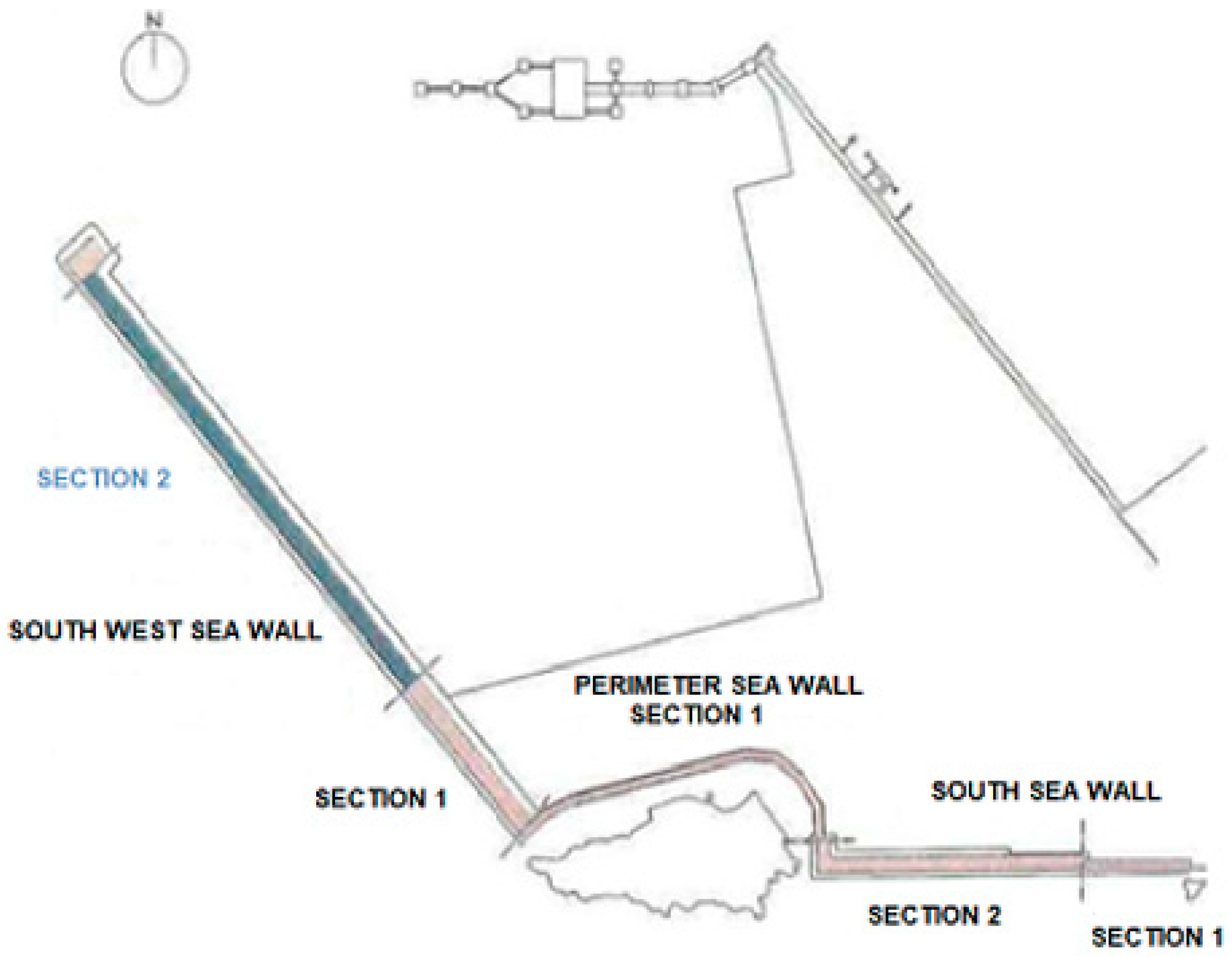
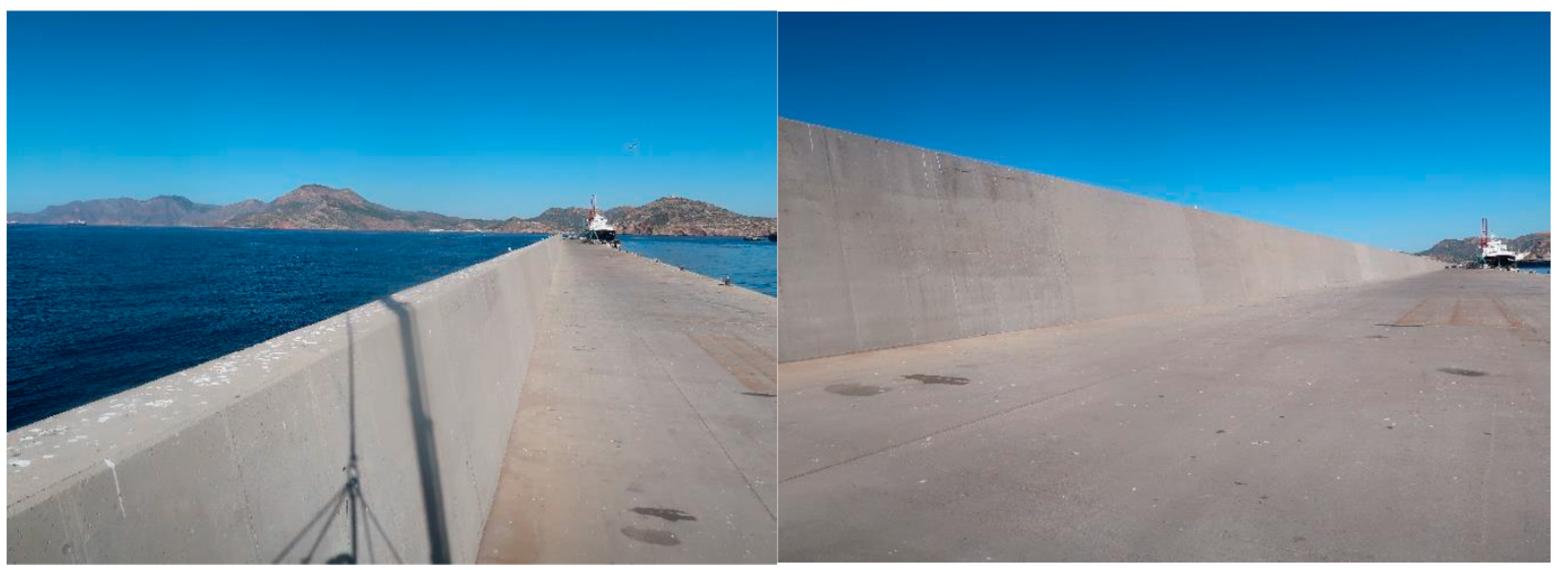
2.2. Structure Description
The studied structure is a part of one of the sea walls of a port located in southeast of Spain, facing the Mediterranean Sea. Nominally it is a part of
Section 2 of the South West sea wall (see
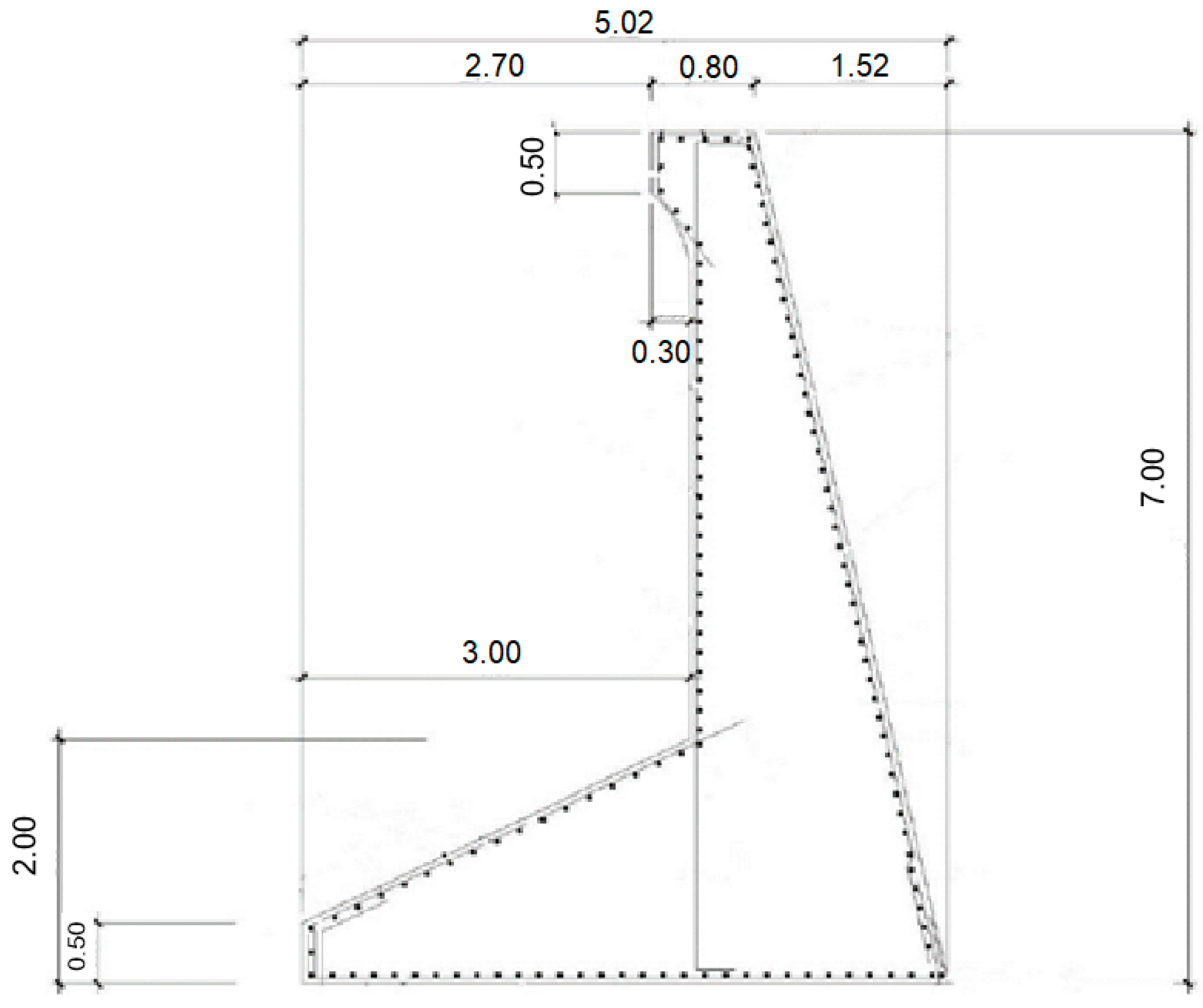
Figure 3). The sea wall, which rests on 22 reinforced concrete caissons, was constructed in 2004, and its total length of the sea wall is 781 m in length and its height is 7 m (
Figure 4).
Technical data of the reinforced concrete used for the project are shown below in
Table 1.
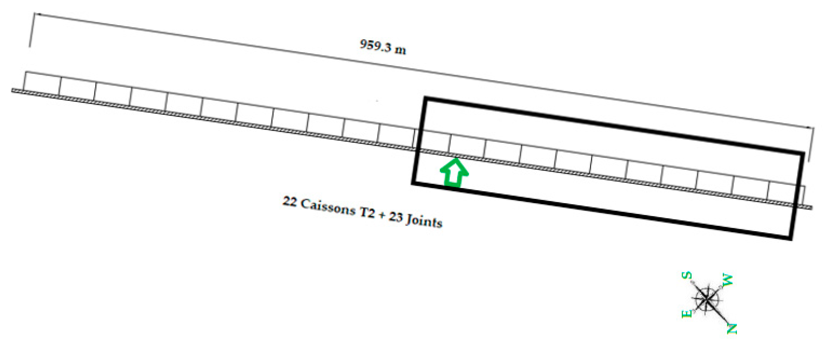
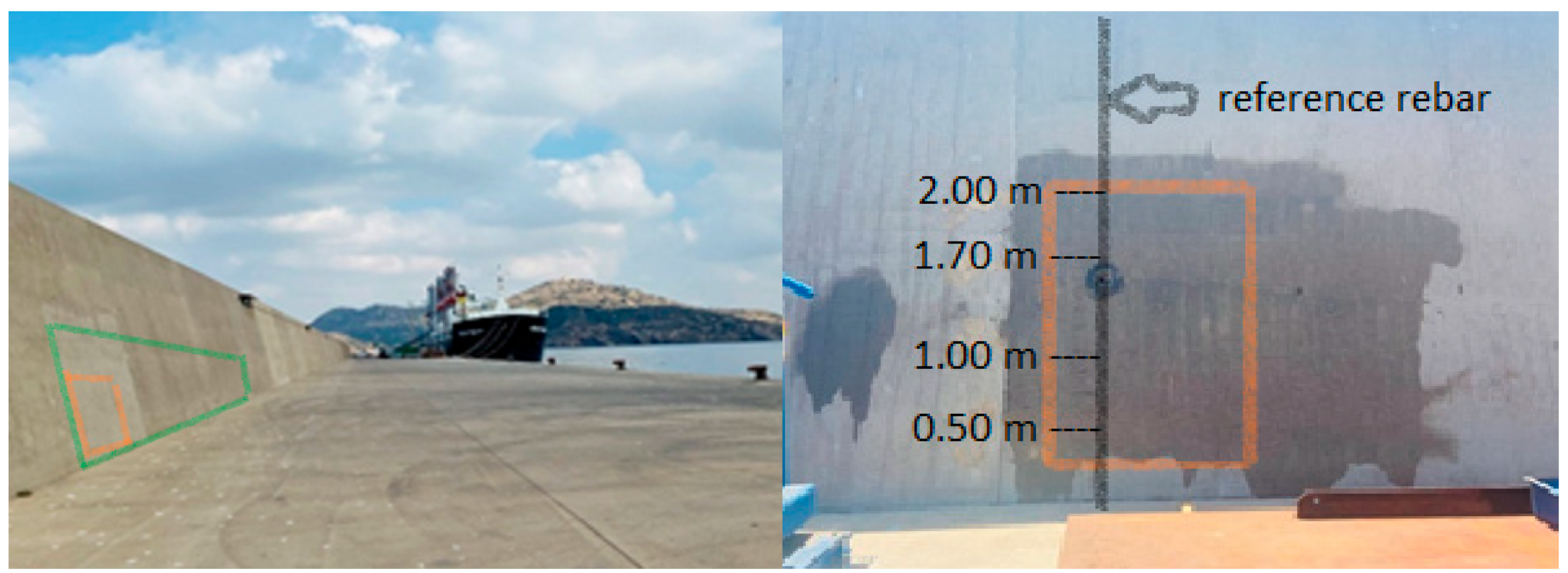
The aim of this study was to prove the effectivity of the dual-phase corrosion inhibitor in an area over the inside vertical sea wall in some areas where incipient corrosion by chlorides (without extreme visual damage) was detected. The chosen location was the interior protected area of the caisson n° 10 (counting from the end of the dock), as shown in
Figure 5. According to Spanish Structural Code EHE-98 [
24], the exposure class is IIIa + Qb (
Table 1.)
The DP-SACI was applied in March 2018, over the internal face of the sea wall on top of the caisson number 10, but only in the first two of the seven meters of height (because of the difficulty providing auxiliary means to reach greater height). The treated surface was around 40 m2 (2.00 m × 20 m). The experimental area for corrosion control measures was selected in caisson 10, close to the joint between caisson 11 and 10 (counted from the end). It was established with a width and height of 1 m and 2 m, respectively (avoiding the use of auxiliary means). The investigated area showed a horizontal crack at 1.65 m height around 0.5 m length with a crack opening of 0.3 mm.
Different pictures showing the general structure and the treated (green) and experimental (orange) area are shown below in
Figure 6.
2.3. Corrosion Assessment of the Structure
Before applying the dual-phase corrosion inhibitor, some tests were performed and taken into consideration.
2.3.1. Carbonation Test
The concrete was broken open by means of hammering (no drilling or sawing). A 1% phenolphthalein indicator (in ethanol) was sprayed on the surface of the freshly broken concrete. After drying, the test showed a carbonated zone up to 15 mm deep from the concrete surface (two samples tested), according to UNE 112011:2011 [
25]. Taking into consideration that the concrete cover over steel is 60 mm (
Table 1), we can exclude the carbonation of concrete as the cause of the steel corrosion process in this part of the wall.
2.3.2. Determination of the Concrete Chloride Contamination
Concrete dust samples were obtained at two depth levels from the concrete surface [
26,
27]; The first samples correspond to a depth between 0 and 25 mm, and the other samples correspond to a depth between 25 and 60 mm (the nominal concrete cover over steel). These results are shown in
Table 2.
The data from
Table 2 indicate that the concrete cover over steel is highly contaminated with chloride ions, with concentrations at the steel rebar depth that can be much higher than the chloride content threshold able to depassivate carbon steel, thus triggering the reinforcement corrosion process. This threshold is usually accepted to range between 0.4 and 1% in reference to the cement mass [
4].
2.4. Corrosion Inhibitor Application
2.4.1. Surface Preparation
A preliminary mechanical soft roughing and cleaning of the concrete surface was made by brushing, to eliminate friable material and dust that could hinder impregnation.
2.4.2. Application
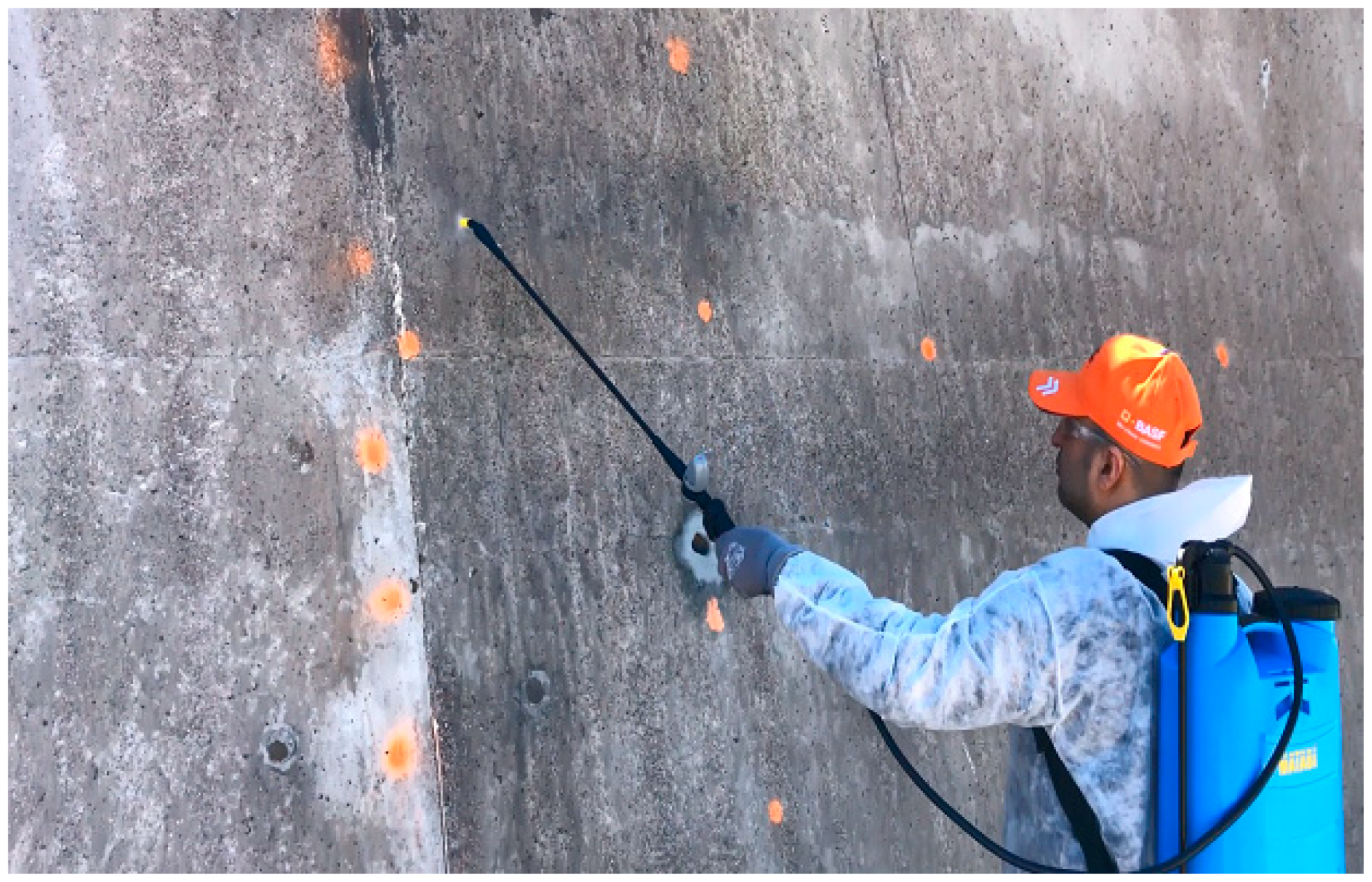
The DP-SACI used in this work (MasterProtect 8500 CI) is a ready-to-use solvent-free liquid (
Figure 7). It was applied to the surface of a selected area of the sea wall by using a high-volume–low-pressure pump with a wet fan-type spray nozzle. The usual recommended application rate of the product on horizontal surfaces is 600 mL/m
2 (distributed in two coats of 300 mL/m
2). However, three coats of 238 mL/m
2 were applied in this case. The increase of dosage was due to the high chloride content found in concrete and the highly negative half-cell potential values obtained. The need to apply three layers was due to the limited concrete’s absorption. A rest drying period of about 15–30 min was allowed between the application of successive layers.
A dual-phase surface-applied corrosion inhibitor (MasterProtect 8500 CI) was applied on 23 March 2018 after taking preliminary measurements of the control parameters.
2.5. On-Site Non-Destructive Measurements of Electrochemical Parameters to Assess the Steel Reinforcement Corrosion Activity
All of the electrochemical parameters were determined in a single preliminary campaign (23 March 2018), before application of the DP-SACI. Later, successive monitoring testing campaigns were performed, at a rate of twice per year (except during 2020 due to the international pandemic situation), for the purpose of determining the effectivity of the product in decreasing the steel reinforcement corrosion activity. The last campaign was carried out in November 2021, but the research project is ongoing and future monitoring campaigns are expected.
2.5.1. Measurement of the Concrete Electrical Resistivity
Electrical resistivity (𝜌) is the bulk electrical resistance to current flow within the concrete and is likely to influence the rate of any active corrosion. For concrete, it varies from 10
6 Ω⋅m for oven-dried samples to 10 Ω⋅m for saturated concrete [
28]. Electrical resistivity is the ratio between applied voltage (𝑉) and resulting current (𝐼) multiplied by a cell constant. The electrical current is carried by ions dissolved in the pore liquid [
29,
30]. Thus, it is a geometry-independent property and an inherent characteristic of a material [
30,
31]:
where:
𝑅 is the resistance of concrete,
k is a geometrical factor that depends on the size and shape of the sample, as well as the distance between the probes on the testing device.
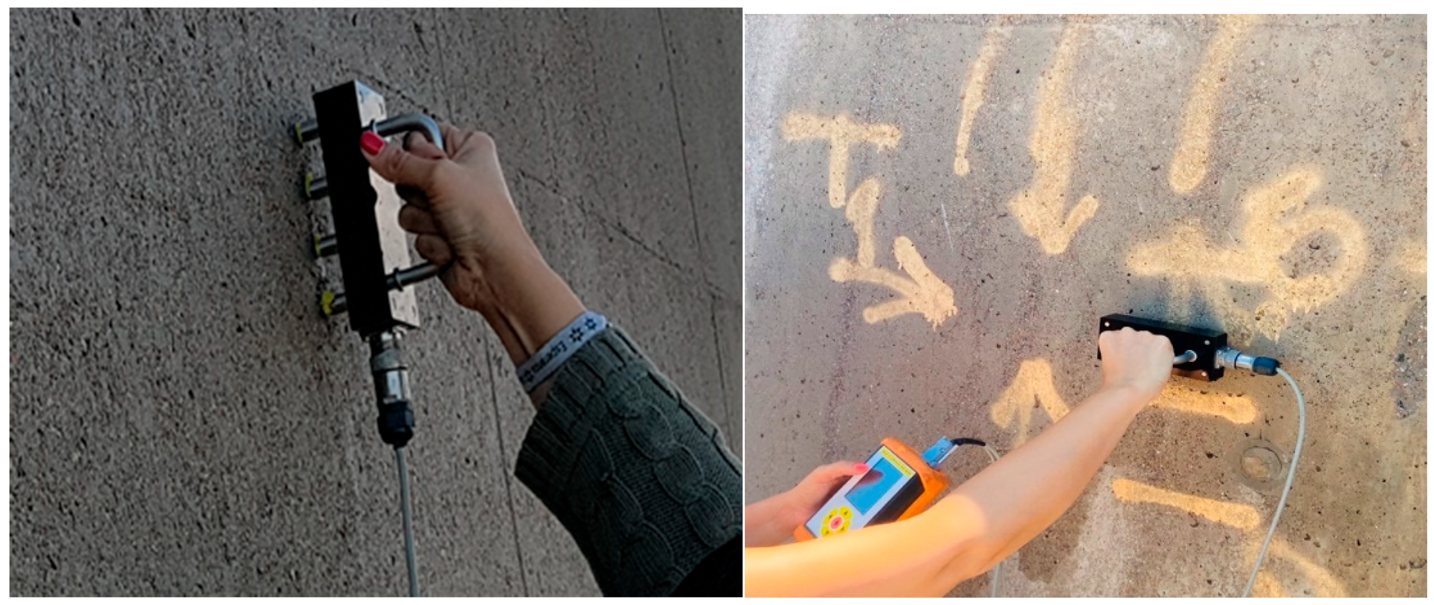
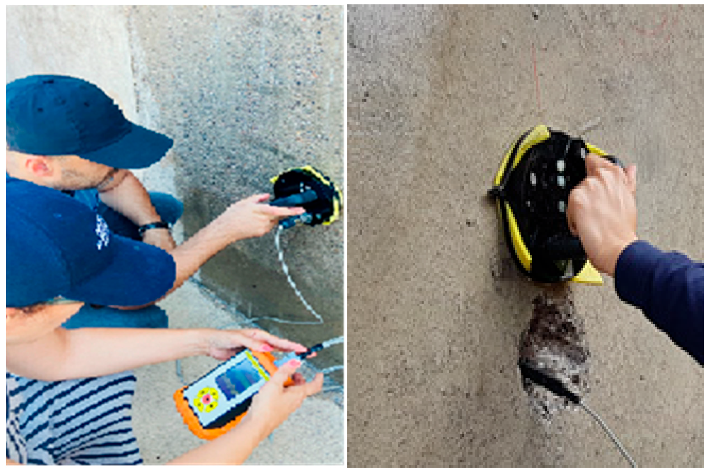
The electrical resistivity was measured using a Wenner four-point probe constituting part of the Gecor 10 equipment (Geocisa, Spain), see
Figure 8. The determination of 𝜌 was done after moistening the concrete’s surface with plenty of potable water, in order to induce a state of the concrete cover close to water saturation, which is needed for the electrochemical measurements. In the Wenner probe technique, four equally spaced linear electrodes are used to measure the surface electrical resistivity of concrete. The two exterior electrodes apply an AC current to the concrete surface, while the electrical potential is measured between the interior probes. [
32].
In addition to evaluating the risk of active corrosion, electrical resistivity can also be used as an index to determine the moisture content and the connectivity of the micropores into the concrete [
33].
Table 3 represents criteria for the evaluation of corrosion risk based on the electrical resistivity values.
2.5.2. On-Site Corrosion Measurements (Icorr and Ecorr)
Evaluation of linear polarization resistance with a Gecor 10 device was used for corrosion measurements (
Figure 9). This non-destructive electrochemical test method provides values of the instantaneous corrosion current density (Icorr), expressed in (µA/cm
2), using a “guard ring” as a counter electrode in order to assess the condition of embedded steel reinforcement in large-scale concrete structures. Values of the free corrosion potential or half-cell potential Ecorr (mV) are obtained as well [
35]. The data were shown in
Table 4 and
Table 5. Using a previously determined rebar size, a small perturbation voltage is applied to the corroding steel bar through a surface auxiliary electrode while a direct electrical connection to the reinforcing steel is made by an alligator clamp or by brazing a protruding rod. A predetermined shift of the rebar potential is produced from its rest or natural value and the current needed to produce the shift is then recorded. A copper–copper sulfate half-cell (SCE) was used as reference for potential measurements.
3. Results
The treated area was evaluated between March 2018 and November 2021 twice a year (except 2020 because of COVID-19 restrictions). Values obtained prior to and after application of DP-SACI are shown delimited by a vertical green dashed line in all figures.
Four points were selected as reference, as shown in
Table 6.
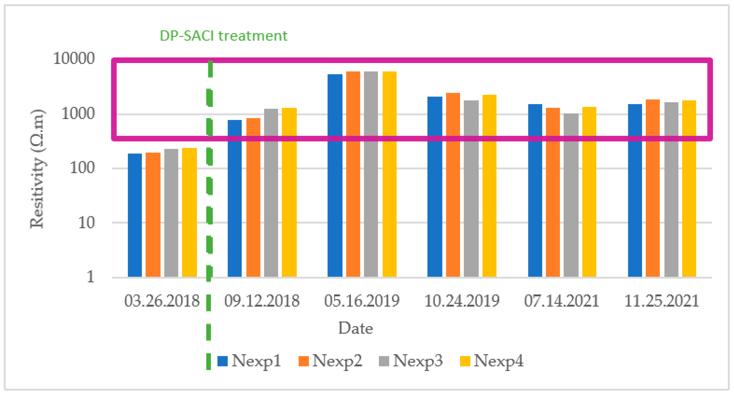
3.1. Electrical Resistivity
The electrical resistivity indicates the resistance of the concrete to the flow of electric charge. It provides information on the risk of corrosion of the steel reinforcement and can serve as an indicator for the effectiveness of the corrosion inhibitor treatment. Electrical resistivity measurements should be taken to avoid rebars, so they were therefore measured near the reference points. Values were taken after a period of water wetting of the exposed concrete.
It was observed that there was an increase in resistivity after application of the DP-SACI, having its lowest value in measurements taken in the spring of 2018, before application of the product. There was a significant increase by May 2019 that could be due to a poor wetting of the surface and that should be corrected and decreased for taking the corrosion rate and corrosion potential measurements (Sensor A of the GCore device needs to adjust for decreased resistivity until the electrical potential is established in order to obtain a valid measurement). On the other hand, subsequent values obtained were quite stable, staying over 10
3 Ohm·m in almost all cases. Therefore, in terms of probabilities according to
Table 3, it could be considered in a region of negligible corrosion risk. This area is shown by the shape in purple color in
Figure 10.
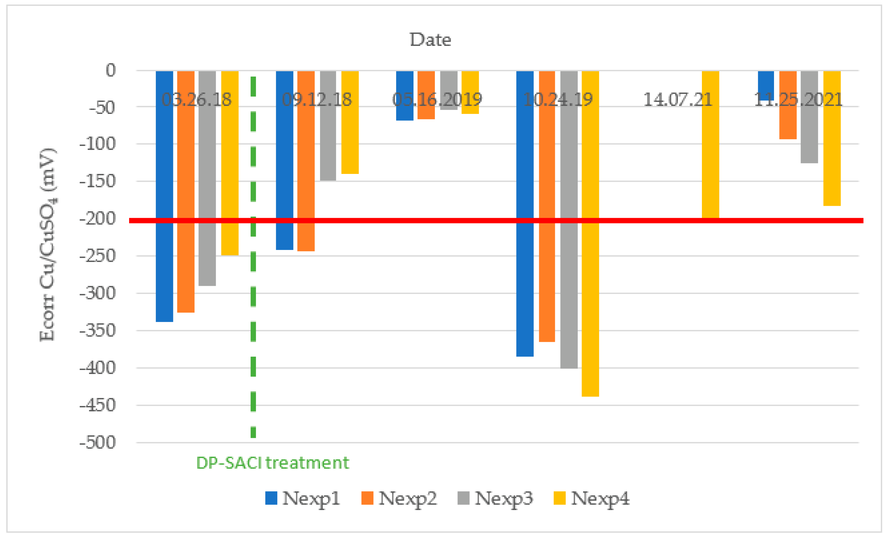
3.2. Half-Cell Potential (Ecorr)
Figure 11 shows the corrosion potential average values registered in each of the evaluated areas during different inspections. It should be noted that practically all the corrosion potential values are less negative than −200 mV after the application of the DP-SACI and, after more than 3 years of treatment, less than 10% probability of corrosion risk could be considered according to the ASTM C876-91 criteria of
Table 4.
During the October 2019 inspection, a large shift to very negative values of half-cell potential at the control area was noticed, which was presumably due to the polarization of the rebars caused by the previous grounding of a ship nearby. On the other hand, in July 2021, unexpected failure of the electrode only allowed taking measurements at point 4 situated at the lowest elevation. In both situations, previous and latest values showed that the potentials were at the low risk level, taking as reference the criteria of ASTM C876-91 (potentials less negative than −200 mV in all points as shown by the red line in
Figure 11). It is also remarkable that at the highest points, the initial corrosion potential was near the −350 mV region, and more time was required to see the potential decrease until values stabilized. This could be due to the influence of a splash zone on the top of the sea wall. That means that the speed of drying is lower on the top at the treated area. Notice that this hypothesis can be reasonable seeing the values of electrical resistivity and corrosion potential in September 2018 (see
Figure 10). In this case, electrical resistivity at the highest points is below 1000 Ohm·m and at the lowest ones, resistivity is above 1000 Ohm·m. It could be also observed that the corrosion potential is more negative higher on the structure (
Figure 11) and that the corrosion rate in the highest points is about 10 times more than that at the lower points below 1.70 m elevation (
Figure 12).
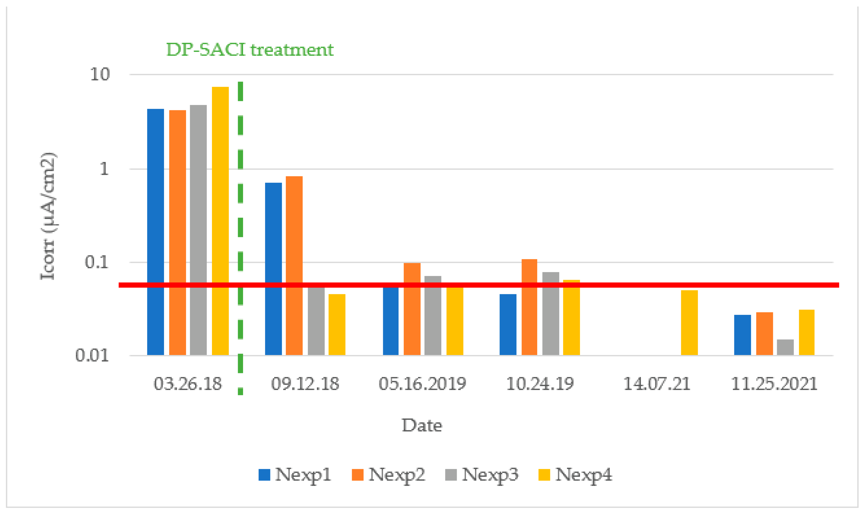
3.3. Corrosion Rate (Icorr)
Corrosion current density or corrosion rate (Icorr) is another parameter that allows evaluation of the corrosion of reinforced concrete structures. By means of the linear polarization resistance (LPR) measurement technique, the reinforcing steel is perturbed by a small amount of potential from its equilibrium. This is achieved by changing the potential of the reinforcing steel by a fixed amount (
ΔE), and observing the current drop (
ΔI), after a set time. The polarization resistance (Rp) of the steel is then calculated from the Equation (2):
Of which the corrosion current is (3):
where B is the Stern–Geary constant with values between 13 and 52 mV in most metal-medium systems. In reinforced concrete, values of 26 mV were assumed for active steel and 52 mV for passive steel [
37] in this study.
The maximum measured corrosion intensity value (0.106 μA/cm
2) after application of the DP-SACI corresponds to a corrosion rate that can be considered negligible. In general, the mean values measured during different seasons are below 0.10 μA/cm
2, implying low rates of corrosion, even when relative humidity conditions are higher as in winter periods, see
Table 7.
4. Discussion
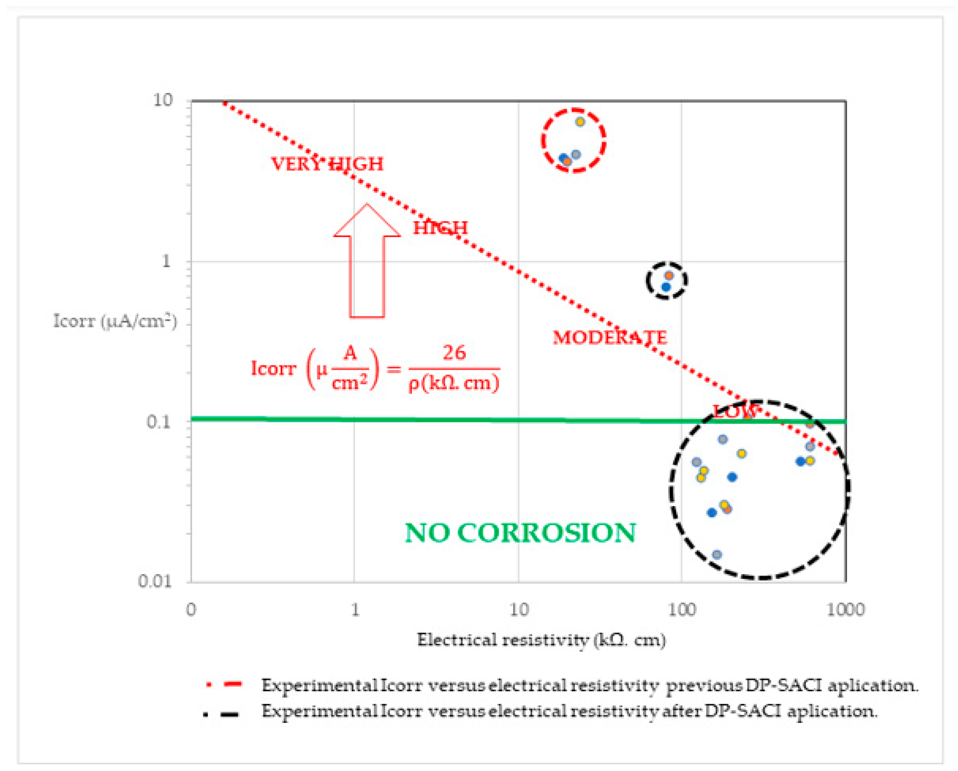
Icorr is subject to resistance control [
38], i.e., it is proportional to the resistance of the medium. Empirical verification of that fact led to the corrosion rate-resistivity (Icorr-electrical resistivity) diagram, from which the following expression was derived:
With that empirical relationship, Icorr can be related to resistivity, in which the diagonal line indicates the theoretical relation usually found between these two parameters [
38,
39] and the corrosion regions are marked following
Table 3 and
Table 5 [
39].
A representation of experimental results is shown in
Figure 13.
Experimental values of Icorr and concrete electrical resistivity are represented following the same color scheme used in previous graphics (blue for Nexp 1, orange for Nexp 2, grey for Nexp 3 and yellow for Nexp 4), and they are grouped under dashed circles colored in red (before DP-SACI application) and black (after DP-SACI application).
Despite the wide dispersion, there is a relationship between both variables that shows a clear correlation for the on-site corrosion measurements obtained.
The experimental relationships of the results clearly demonstrate how after the application of the DP-SACI, the values move to the area of greater resistivity and a corresponding lower corrosion rate. The results are in concordance with others’ investigations [
38,
39]. It can be corroborated and concluded that in the investigated area, negligible corrosion was observed after DP-SACI application.
The effectivity of an inhibitor can be calculated and expressed as a percentage characterized by the expression (5):
This expression is based on the value of the corrosion rate before and after application of the inhibitor by its magnitude. This result applies to measurement of either the corrosion rate by weight loss or by electrochemical techniques [
40,
41]. Polarization curves or Electrochemical Polarization resistance (Rp) are considered the preferred techniques to evaluate the effectivity of the inhibitors. Effectivity then can be quantified by using the expression (5) with the values of the corrosion current in the presence and absence of inhibitor from the
Table 8.
DP-SACI effectivity results, from the values measured at the different points and data, are shown in
Table 9.
A very effective inhibition of the corrosion process is achieved in all the control points after almost four years.
5. Conclusions
ACI 318-14 [
42] and EHE-08 [
43] specify the maximum water-soluble chloride ion in concrete as a percent by weight of cement. Therefore, the chloride content in reinforced concrete must also be considered in order to provide long-term effectiveness. When the chloride threshold is exceeded, corrosion induced by chloride starts and the application of the dual-phase surface-applied corrosion inhibitor was shown to be effective in the existing reinforced concrete structure, containing more than 2% chloride concentration by cement weight.
For this test series in the sea wall, studied over almost four years in real conditions and seaside natural exposure class XS1and eventually XS3 [
43], DP-SACI (MasterProtect 8500 CI) demonstrated effective corrosion inhibition and durability, even in concrete with nearly 3% chloride by cement weight with efficiencies of over 99%. It is also remarkable that a good correlation with experimental results was found for CEM I [
44], even taking into consideration the presence of fly ash.
The influence of the hydrophobic effects on the corrosion inhibition and the reduction of macro-element corrosion currents was also observed through the increase in resistivity, but also as an increase in corrosion potential until reaching values approaching areas associated with negligible corrosion risk. A decrease in the corrosion rate with values below 0.1 μA/cm2 was obtained.
The effective inhibition of the corrosion processes, during these long-term measurements are a remarkable result for designing new strategies for corrosion control, oriented to the sustainability and durability of reinforced concrete structures in chloride exposure environments.
The use of DP-SACI in corrosion control represents a step forward in enhancing repair and protection techniques of structures with active chloride-induced corrosion, inhibiting corrosion, even over the assumed threshold. Electrical resistivity is considered a microstructural parameter for the calculation of the corrosion rate (Icorr) for estimating service life [
45], and it is an easy way to obtain valuable information about the corrosion control effectiveness of the treatment.
The corrosion inhibitor effectiveness and its influence on the chloride threshold has been demonstrated in on-site structures with active corrosion. The steel reinforcement after DP-SACI application can be classified as “passive”, which means a proven increase in durability and extended service life, with reduced corrosion damage expected in XS1 and XS3 exposure classes [
43,
46], where a durability classification system, whereby a deterioration mechanism, is considered with the ambient environment.
The expected increase of service life of the structure and the durability of the DP-SACI protection is not only based on the initial increase of electrical resistivity resulting from water repellency. Despite the open crack of 0.3 mm over the cross-section of the rebar, the dual-phase effect was demonstrated with greatly reduced corrosion. This observation reveals the very good behavior of the latent phase despite seasonal thermal changes of the concrete. On the other hand, the MasterProtect 8500CI DP-SACI application is easy, fast and preserves the aesthetic appearance of concrete.
The use of low-invasive techniques and solutions with new technologies, oriented to improve the life-cycle cost values- and to increase service life, provides an important contribution to the sustainability and durability in chloride-exposed reinforced concrete structures. There is an open field of study for both the discrete and continuous monitoring of the effectiveness of corrosion inhibitors in refurbishment, as well as to acquire the knowledge for good practices in protecting reinforced concrete structures affected by corrosion.
Author Contributions
Conceptualization, D.M. and E.S.; methodology, D.M. and E.S.; validation D.M.; formal analysis, D.M.; investigation, D.M. and E.S.; resources, D.M.; writing—original draft preparation, D.M.; writing—review and editing, D.M.; supervision, D.M.; project administration, D.M. and E.S. All authors have read and agreed to the published version of the manuscript.
Funding
This research received no external funding.
Data Availability Statement
The data presented in this study are available on request from the corresponding author.
Acknowledgments
I express gratitude to the Cartagena Port Authority, which kindly allows us to use one of its structures for this study, and also for all the facilities provided. Their remarkable commitment to innovation and development is focused on port structures’ maintenance and durability (D. Martín). Many thanks also to Carmen Andrade and Miguel Angel Climent for encouraging me to share our research with the scientific community and who always share their knowledge, suggestions and technical background with enthusiasm and patience (D. Martín). I would also especially acknowledge Fred Goodwin (retired), FASTM, FACI, FICRI and former Head of the EB Global Corrosion Competency Center in Master Builders Solutions U.S., for his support during the investigation process in the Beachwood Headquarters as well as for being one of the best mentors I have had, not only as a prestigious member of the corrosion community, but also for his generosity and kindness as a person (D. Martin).
Conflicts of Interest
Both authors of the manuscript are employees of Master Builder Solutions. They are involved in corrosion mitigation techniques’ strategy and development.
References
- Koch, G.H.; Brongers, M.P.H.; Thompson, N.G.; Virmani, Y.P.; Payer, J.H. FHWA-RD-01-159; Report, Corrosion Costs and Preventive Strategies in the United States; FHWA: Washington, DC, USA, 2001. [Google Scholar]
- Andrade, C.; Alonso, C. Electrochemical Techniques for Measuring Metallic Corrosion, RILEM TC 154_EMC. Mater. Struct. 2004, 38, 623–643. [Google Scholar] [CrossRef]
- Tuutti, K. Corrosion of Steel in Concrete; Swedish Cement and Concrete Research Institute: Stockholm, Sweden, 1982. [Google Scholar]
- Wittmann, F.H. Effective chloride barrier for reinforced concrete structures in order to extend the service-life. In Advances in Construction Materials 2007; Grosse, C.U., Ed.; Springer: Berlin/Heidelberg, Germany, 2007; pp. 427–437. [Google Scholar]
- Otieno, M.; Beushausen, H.; Alexander, M. Chloride-induced corrosion of steel in cracked concrete–Part I: Experimental studies under accelerated and natural marine environments. Cem. Concr. Res. 2016, 79, 373–385. [Google Scholar] [CrossRef]
- ISO 8044-2015; Glossary of Terms for Corrosion of Metals and Alloys. ISO: Geneva, Switzerland, 2015.
- Broomfield, J.P. Corrosion inhibitors for steel in concrete. Concrete 1999, 33, 44–47. [Google Scholar]
- Söylev, T.A.; Richardson, M.G. Corrosion inhibitors for steel in concrete: State-of-the art report. Constr. Build. Mater. 2008, 22, 609–622. [Google Scholar] [CrossRef]
- Söylev, T.A.; McNally, C.; Richardson, M.G. The effect of a new generation surface applied organic inhibitor on concrete properties. Cem. Concr. Compos. 2007, 29, 357–364. [Google Scholar] [CrossRef]
- Tritthart, J. Transport of a surface-applied corrosion inhibitor in cement paste and concrete. Cem. Concr. Res. 2003, 33, 829–834. [Google Scholar] [CrossRef]
- Ormellese, M.; Bolzoni, F.; Perez, E.R.; Goidanich, S. Migrating corrosion inhibitors for reinforced concrete structures. In 2007 NACE Corrosion Conference; NACE International: Nashville, TN, USA, 2007; pp. 1–16. [Google Scholar]
- Kepler, J.L.; Darwin, D.; Locke, C.E., Jr. Evaluation of corrosion protection methods for reinforced concrete highway structures. In SM Report; University of Kansas Center for Research: Lawrence, KS, USA, 2000. [Google Scholar]
- Andrade, C.; Alonso, C.; Acha, M.; Malric, B. Preliminary testing of Na2PO3F as a curative corrosion inhibitor for steel reinforcements in concrete. Cem. Concr. Res. 1992, 22, 869–881. [Google Scholar] [CrossRef]
- Alonso, C.; Andrade, C.; Argiz, C.; Malric, B. Na2PO3F as inhibitor of corroding reinforcement in carbonated concrete. Cem. Concr. Res. 1996, 26, 405–415. [Google Scholar] [CrossRef]
- Maeder, U. A new class of corrosion inhibitors for reinforced concrete. In Proceedings of the 3rd CANMET/ACI International Conference on Concrete in Marine Environment, St. Andrew, NB, Canada, 4–9 August 1996. [Google Scholar]
- Söylev, T.A.; McNally, C.; Richardson, M. Effectiveness of amino alcohol-based surface-applied corrosion inhibitors in chloride-contaminated concrete. Cem. Concr. Res. 2007, 37, 972–977. [Google Scholar] [CrossRef]
- Ngala, V.T.; Page, C.L.; Page, M.M. Corrosion inhibitor systems for remedial treatment of reinforced concrete Part2: Sodium monofluorophosphate. Corros. Sci. 2003, 45, 1523–1537. [Google Scholar] [CrossRef]
- FHWA-RD-01-097; Long-Term Performance of Corrosion Inhibitors Used in Repair of Reinforced Concrete Bridge Components. Federal Highway Administration Research and Technology: Washington, DC, USA, 2002.
- Elsener, B. Corrosion inhibitors for steel in concrete. In Proceedings of the International Congress on Advanced Materials, Munich, Germany, 25–28 September 2000. [Google Scholar]
- Ormellese, M.; Berra, M.; Bolzoni, F.; Pastore, T. Corrosion inhibitors for chloride induced corrosion in reinforced concrete structures. Cem. Concr. Res. 2006, 36, 536–547. [Google Scholar] [CrossRef]
- Schiegg, Y.; Hunkeler, F.; Ungricht, H. The effectiveness of corrosion inhibitors–A field study, In Proceedings of the 16th Congress of IABSE, Lucerne, Switzerland, 18–21 September 2000.
- Al-Kheetan, M.; Rahman, M.M.; Chamberlain, D.A. Fundamental interaction of hydrophobic materials in concrete with different moisture contents in saline environment. Constr. Build. Mater. 2019, 207, 122–135. [Google Scholar] [CrossRef]
- Dai, J.-G.; Akira, Y.; Wittmann, F.; Yokota, H.; Zhang, P. Water repellent surface impregnation for extension of service life of reinforced concrete structures in marine environments: The role of cracks. Cem. Concr. Compos. 2010, 32, 101–109. [Google Scholar] [CrossRef]
- EHE-98. Spanish Structural Code. Exposure classes relating to structural concrete. Annex: Table 8.2.2., Table 8.2.3.a and Table 8.2.3.b. Real Decreto 2661/1998. Spanish Government. 1998.
- UNE 112011:2011; Corrosion of Concrete Reinforcement Steel. Determination of the Carbonatation Depth for in-Service Concrete. Asociación Española de Normalización AENOR: Madrid, Spain, 2011.
- UNE 112010:2011; Corrosion of Concrete Reinforcement Steel. Chloride Determination for in-Service Concrete. Asociación Española de Normalización AENOR: Madrid, Spain, 2011.
- Vennesland, Ø.; Climent, M.A.; Andrade, C. Recommendation of RILEM TC 178-TMC: Testing and modeling chloride penetration in concrete. Methods for obtaining dust samples by means of grinding concrete in order to determine the chloride concentration profile. Mater. Struct. 2013, 46, 337–344. [Google Scholar]
- Whitting, D.A.; Nagi, M.A. Electrical Resistivity of Concrete; Portland Cement Association: Skokie, IL, USA, 2003. [Google Scholar]
- Polder, R.B. Test methods for on site measurement of resistivity of concrete—A RILEM TC-154 technical recommendation. Constr. Build. Mater. 2001, 15, 125–131. [Google Scholar] [CrossRef]
- Elsener, B.; Andrade, C.; Gulikers, J.; Polder, R.; Raupach, M. Recommendations of RILEM TC 154-EMC: “Electrochemical techniques for measuring metallic corrosion” Half-cell potential measurements—Potential mapping on reinforced concrete structures. Mater. Struct. 2003, 36, 461–471. [Google Scholar] [CrossRef]
- Layssi, H.; Ghods, P.; Alizadeh, A.R.; Salehi, M. Electrical resistivity of concrete. Concr. Int. 2015, 37, 41–46. [Google Scholar]
- Wenner, F. A Method of Measuring Earth Resistivity. Bull. Bur. Stand. 1916, 12, 469–478. [Google Scholar] [CrossRef]
- Rajabipour, F.; Weiss, J.; Abraham, D.M. Insitu electrical conductivity measurements to assess moisture and ionic transport in concrete (A discussion of critical features that influence the measurements). In International RILEM Symposium on Concrete Science and Engineering: A Tribute to Arnon Bentur; RILEM Publications SARL: Paris, France, 2004. [Google Scholar]
- Brown. Resistivity ranges related to the risk of corrosion. Durability of Building Materials. 1992.
- Alonso, C.; Andrade, C. Recommendations of RILEM TC-154-EMC: “Electrochemical techniques for measuring metallic corrosion” Test methods for on-site corrosion rate measurement of steel reinforcement in concrete by means of the polarization resistance method. Mater. Struct. 2004, 37, 623–643. [Google Scholar]
- ASTM C876-91 (Reapproved 1999); Test Method for half-Cell Potentials of Uncoated Reinforcing Steel in Concrete. ASTM: West Conshohocken, PA, USA, 1991.
- Feliu, V.; González, J.A.; Andrade, C.; Feliu, S. Equivalent circuit for modelling the steel-concrete interface. I. experimental evidence and theoretical predictions. Corros. Sci. 1998, 40, 975–993. [Google Scholar] [CrossRef]
- Andrade, C.; Fullea, J.; Alonso, C. The use of the graph corrosion rate-resistivity in the measurement of the corrosion current. In Rilem Proceedings No. 18: Measurement and Interpretation of the on-Site Corrosion Rate; RILEM Publications SARL: Paris, France, 1999; pp. 157–165. [Google Scholar]
- Andrade, C.; D’Andrea, R. Electrical resistivity as microstructural parameter for the calculation of reinforcement service life. Microstruct. Relat. Durab. Cem. Compos. 2008, 1, 1483–1490. [Google Scholar]
- Gouda, K.V.; Monfore, E.G. A Rapid Method for Studying Corrosion Inhibition of Steel in Concrete; Accession Number 00213624; Portland Cement Association: Skokie, IL, USA, 1965. [Google Scholar]
- Andrade, C.; Gonzalez, J.A. Quantitative measurements of corrosion rate of reinforcing steels embedded in concrete using polarization resistance measurements. Werkst. Korros. 1978, 29, 515. [Google Scholar] [CrossRef]
- ACI 318-14; Building Code Requirements for Structural Concrete. ACI: Farmington Hills, MI, USA, 2014.
- EHE-08; Spanish Code for Structural Concrete. ASIDAC: Dos Hermanas, Spain, 2008.
- Seyhan, E.; Ebell, G.; Martin, D. Evaluation of surface applied corrosion inhibitor performance on reinforced concrete structures. In Proceedings of the VIII ACHE Congress, Santander, Spain, 20–22 June 2022. [Google Scholar]
- CONTECVET-A Validated User´s Manual for Assessing the Residual Life of Concrete Structures, DG Enterprise, CEC. 2001. Available online: http://www.ietcc.csic.es/index.php/es/publicaciones-2/manual-contecvet (accessed on 29 June 2022).
- EN 206; Concrete—European Standard. Specification, Performance, Production and Conformity. Comité Europeo de Normalización (CEN): Brussels, Belgium, 2013.
| Publisher’s Note: MDPI stays neutral with regard to jurisdictional claims in published maps and institutional affiliations. |
© 2022 by the authors. Licensee MDPI, Basel, Switzerland. This article is an open access article distributed under the terms and conditions of the Creative Commons Attribution (CC BY) license (https://creativecommons.org/licenses/by/4.0/).


