Review

Vapor Compression Cycle: A State-of-the-Art Review on Cycle Improvements, Water and Other Natural Refrigerants

1
School of Mechanical and Mechatronic Engineering, University of Technology Sydney, Ultimo, NSW 2007, Australia
2
School of Engineering, Macquarie University, Macquarie Park, NSW 2109, Australia
*
Author to whom correspondence should be addressed.
Clean Technol. 2023, 5(2), 584-608; https://doi.org/10.3390/cleantechnol5020030
Submission received: 16 February 2023 / Revised: 12 April 2023 / Accepted: 2 May 2023 / Published: 5 May 2023
(This article belongs to the Collection Review Papers in Clean Technologies)

Abstract

:
Air conditioning and refrigeration have become necessary in modern life, accounting for more than 7.8% of greenhouse gases (GHG) emitted globally. Reducing the environmental impact of these systems is crucial for meeting the global GHG emission targets. Two principal directions must be considered to reduce the environmental impact of air conditioning systems. Firstly, reducing the direct effect by looking at less harmful refrigerants and secondly, reducing the indirect effect by searching for options to improve the system efficiency. This study presents the latest developments in the vapor compression cycle and natural refrigerants, focusing on water as a refrigerant. Natural refrigerants, and especially water, could be the ultimate solution for the environmental problems associated with the operation of vapor compression cycle (VCC) cooling systems, including ozone depletion (OD) and global warming (GW). Reducing the environmental impact of building cooling systems is essential, and the recent system improvements made to enhance the system coefficient of performance (COP) are thoroughly discussed in this paper. Though the cycle improvements discussed in this work are essential and could increase the system efficiency, they still need to solve the direct environmental impact of refrigerants. Accordingly, this paper suggests that natural refrigerants, including water, are the most suitable strategic choice to replace the current refrigerants in the refrigeration and air conditioning industry. Finally, this study reviews the latest VCC system improvements and natural refrigerants in order to guide interested researchers with solutions that may reduce the environmental impact of VCC systems and suggest future research areas.

1. Introduction

Global energy consumption has grown dramatically in the last few decades and reached 636 EJ in 2021 compared to 230 EJ in 1971, representing a growth of around 276% in 50 years [1]. Among all sectors, buildings are considered one of the significant contributors, accounting for around 40% of total global energy consumption, and are responsible for 30% of greenhouse gas emissions. Moreover, buildings’ energy consumption is expected to grow by approximately 184.2 EJ by 2050. Figure 1 shows the global energy consumption by sector, with around 60% being consumed in residential and commercial buildings [2].
HVAC systems account for a large proportion of building energy consumption. Thus, HVAC system improvements offer the potential for energy saving. For instance, it represents more than 50% of the total building energy consumption in the United States [3]. Depending on Australia’s climate zone, HVAC equipment is responsible for 20–50% of the total energy used in buildings [4]. Moreover, refrigeration and air conditioning are responsible for 7.8% of global greenhouse gas emissions, which is distributed between the direct effect of the refrigerant itself (37%) and the indirect impact caused by the powerplants that generate energy for these systems [5].
HVAC equipment consumes energy to achieve human comfort, mostly to enhance human thermal comfort. Most buildings’ HVAC systems worldwide work on the vapor compression refrigeration (VCR) cycle, which makes any improvement in the cycle performance of great value. The history of the VCR cycle goes back to the 18th century when the first system was introduced based on the Carnot cycle principle. The main difference between the VCR system and any other thermal system is its ability to transfer thermal energy from the low-temperature space to the higher-temperature space using the latent fluid heat of vaporisation and condensation. VCR systems mainly consist of an evaporator, condenser, compressor, expansion valve, controller, and refrigerant [6]. Although the VCC is considered one of the most efficient thermodynamic cycles ever made due to its high coefficient of performance (COP), it still accounts for the most significant portion of energy consumption in buildings. Moreover, it contributes to other environmental challenges directly and indirectly [7].
The refrigerants, as a working fluid in the VCC, have a significant direct impact on the environment caused by their direct relation to ozone layer depletion and global warming. Many fluid options can be used as refrigerants. However, many factors must be considered when selecting the refrigerant, including the latent heat of vaporisation, the boiling temperature, critical pressure, critical temperature, heat capacity, and specific volume at the vapor state. Many other factors define the capabilities, performance and cycle limitations, as well as the cost of the equipment. Natural refrigerants such as CO2, Ammonia, hydrocarbons, water, etc., could reduce the direct environmental impact of VCC-based cooling systems. However, the indirect effect relates to the efficiency of these systems, which raises the need to make sure that the COP of the system is not compromised. Water has favourable thermodynamic properties, such as a high latent heat of vaporisation, a high critical pressure and temperature, a high thermal capacity, and chemical stability, among all known natural refrigerants. However, it has a high boiling temperature [8]. Water has no negative impact on the environment, and it is available in the environment in large quantities.
On the other hand, water has a very high specific volume in the vapor state, adding some technical challenges to the design of the system. In addition, it has a high boiling temperature, requiring the system to operate at a low pressure. Thus, if a solution for the technical challenges of using water as a refrigerant is found, it could be the ultimate solution for the environmental impact of the refrigeration cycle. This could achieve excellent efficiency, reduce the indirect environmental impact and, at the same time, have almost zero direct effect on the environment [9].
As this study aims to find a solution for buildings’ cooling systems’ environmental impact, it is worth highlighting that some passive techniques can reduce the dependency on fossil fuels when cooling buildings, including earth–air heat exchangers and passive radiative cooling [10]. Earth air heat exchangers use the earth’s thermal inertia at a certain depth under the ground and uses the earth as a heat sink. Passive radiative cooling is also a renewable cooling method that uses a thermally emissive surface to enhance the heat flow; these surfaces are designed to minimise heat gain during the daytime. Passive radiative cooling panels can be designed to be self-adaptive in order to enable switching from cooling to heating to deal with overcooling effects [11].

2. Refrigeration Cycle Improvements

The basic principle of the vapor compression refrigeration system is to utilise the fluid properties of the pressure-related boiling temperature and the latent heat of phase change to transfer heat from the lower temperature side to the higher temperature side of the cycle. In the VCC, the refrigerant boiling point varies with pressure; it boils at a low pressure, absorbing heat from the lower temperature space; then, by compressing the refrigerant to a higher pressure, it condenses to a liquid that releases energy to the higher temperature space. This fundamental principle applies to vapor compression refrigeration or air conditioning systems, from a small room air conditioner to a large tonnage chiller. Figure 2 shows the VCC components.
The main component of the VCC is the compressor, which accounts for most of the system power consumption; the compressor technologies are many and evolving but can be classified into three main types:
  • Positive displacement, such as reciprocating and linear compressors
  • Rotary, including scroll, screw, root, and rolling compressors
  • Kinematic compressors, such as centrifugal and axial compressors
Improving the refrigeration system’s COP is not limited to improving the compressor efficiency, but it also includes many other techniques, such as expansion-stage energy recovery, refrigerant sub-cooling and superheating.
The vapor compression cycle consists of a circulating refrigerant in a closed loop of four stages. In the first stage, the refrigerant enters the compressor at low pressure and in a vapor state; in this stage, the refrigerant is compressed to a high-pressure vapor. In the next stage, the refrigerant enters the condenser as high-pressure and high-temperature vapor, forcing it through the condenser coil. At the same time, another fluid passes the other side of the coil to cool the refrigerant down so that it condenses to a high-temperature/pressure liquid. After that, the refrigerant moves to the expansion stage, where it is forced through an expansion device, such as a thermal expansion valve, orifice, capillary tube or electronic expansion valve, to reduce the refrigerant pressure and leaves it as a low-pressure liquid. Finally, the refrigerant enters the fourth stage as a low-pressure liquid, absorbs heat from the conditioned space or the cooling fluid, and leaves the evaporator as a superheated vapor at low pressure. Figure 2 shows the four stages of the refrigeration cycle.
The vapor compression cycle could be improved by applying different techniques. To achieve that goal, we will discuss them in detail in this section by looking at the energy waste in each cycle component and looking at options to reduce or recover that energy.

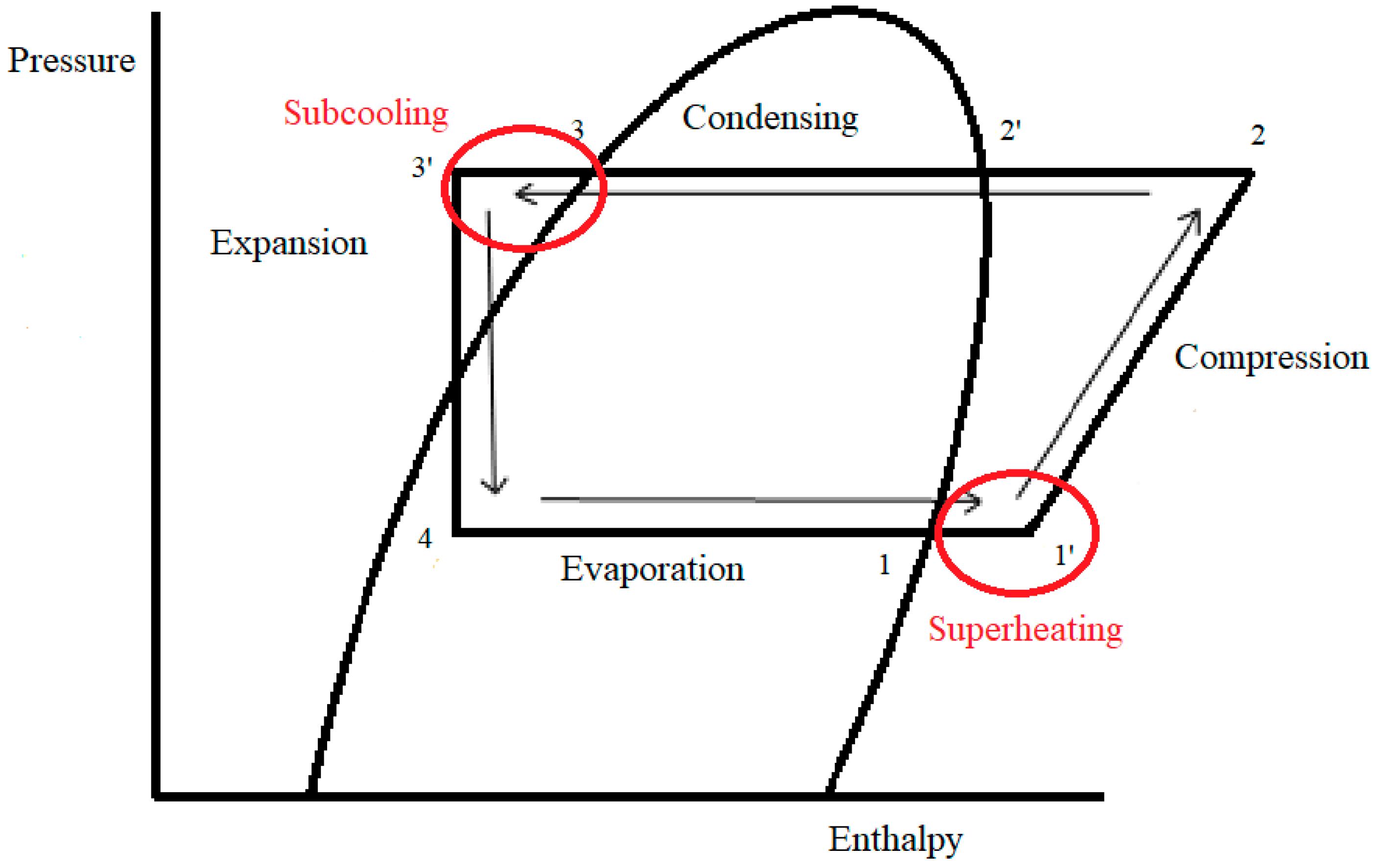
2.1. Cycle Improvement by Increasing Sub-Cooling and Superheating

Sub-cooling could be identified as decreasing the refrigerant temperature below its condensing temperature at a specific pressure. On the other hand, superheating increases the refrigerant temperature above the boiling temperature at a specific pressure. Figure 3 shows the effect of superheating and sub-cooling on the cycle capacity and the system COP. Sub-cooling is commonly increased in three main ways:
  • Suction Line Heat Exchanger (SLHX)
  • Mechanical Sub-cooling (MS)
  • Thermoelectric Sub-cooling (TS)

2.1.1. Suction Line Heat Exchanger (SLHX)

The suction line heat exchanger is used to exchange heat between the expansion device inlet (sub-cooling) and the compressor inlet (superheating) to improve the system efficiency by increasing the evaporator capacity. On the other hand, applying a SLHX in the refrigeration cycle elevates the compressor inlet vapor temperature, decreasing the volumetric compressor efficiency and affecting the system efficiency. Thus, optimisation is required to achieve the best outcome when using a SLHX. Domanski et al. [12] investigated the benefits of using a SLHX with different refrigerants with variable operating conditions. The study showed that the refrigerant thermodynamic properties highly influence the COP of the system. Figure 4 shows a diagram of the VCC with a SLHX and the effect of using the SLHX on the capacity of the VCC, as represented in the enthalpy/pressure chart; it is clear that using a SLHX results in increasing the system cooling capacity with a minor impact on the compressor volumetric efficiency. However, the impact of the SLHX on the cycle depends on the refrigerant properties and does not provide a similar result for all refrigerants [13].
Klein et al. [14] studied the effect of applying a SLHX on the COP of the refrigeration cycle using a group of refrigerants. The study showed a strong relationship between the system COP improvement and the refrigerant thermodynamic properties. In addition, it showed that the SLHX is more effective for refrigerants with a lower latent vaporization temperature and heat capacity, mainly when the system operates on a relatively high-temperature lift. Furthermore, the authors of this study concluded that the SLHX was more efficient for systems that used R-410a, R134a, R-290 and R-404; simultaneously, it showed the best results with R-744 (carbon dioxide). However, it was detrimental with R-32 and R-717 (Ammonia). Hwang et al. [15] proposed a SLHX for high-temperature heat pump applications and reported a COP improvement of 7% for the single-stage compression cycle and 18% for the double-stage compression cycle. The reason for the difference in performance was not clearly discussed, but could be referred to the higher temperature difference in the case of double-stage compression, which allows for a more efficient heat transfer process within the SLHX. Cho et al. [16] investigated the potential improvements in the R-744 refrigeration cycle by using a variable speed compressor, electronic expansion valve, and internal heat exchanger or a SLHX; the study reported that the SLHX improved the cycle COP by 8%, which agrees with previous studies for the single-stage compression of the R-744 refrigerant. In 2000, Preissner et al. [13] investigated the effect of using a SLHX on the performance of an R-134a automotive air-conditioning system with a 40 °C condenser temperature. The study reported a 5–10% improvement in the system COP. Moreover, the authors proposed R-1234yf as a replacement for R-134a because it provides similar thermodynamic properties but with a lower heat of vaporisation. Accordingly, it offers a lower capacity for the same compressor size, which makes it suitable for the SLHX. The SLHX was applied to R-134a and R-1234yf systems as a solution for the capacity loss when using R-1234yf, which improved the system cooling capacity by 2–9%; the COP of the system was not stressed enough in this study, as the main objective was to study the cooling capacity [17,18]. Cho et al. [19] investigated the effect of using a SLHX on the COP and the cooling capacity of R-1234yf and R-134a systems; the study showed that by using R-1234yf as a replacement for R-134a without a SLHX, the COP decreased by 4.5% and the cooling capacity dropped by 7%. However, when using a SLHX, the system losses could be limited to 1.8% and 2.9% for the COP and the cooling capacity, respectively; a complete environmental lifetime assessment is necessary to conclude whether the R-1234yf cycle that uses a SLHX provides an advantage over the R-134a. In 2015, Pottker and Hrnjak [20] carried out an experimental study on the effect of sub-cooling on the performance of R-134a and R1234yf refrigeration systems; the authors concluded that sub-cooling yields more energy efficiency when used with R-1234yf, proving that the SLHX effectiveness depends on the refrigerant properties. Prabakaran et al. [21] studied the implementation of a SLHX on a mobile air conditioner to improve system efficiency. In this study, R-134a was used, and the study reported an improvement in the COP of the system from 2.8% to 11.8% when using different thermostatic expansion valve settings, which clearly shows that the SLHX performance is not only dependent on the refrigerant properties, but on the cycle parameters as well.
Mahdi Al-Obaidi et al. [22] conducted an experimental study to improve the performance of the VCC working with R22 refrigerants and using a SLHX on different cooling loads. The authors reported a 10% COP improvement in the best-case scenario. In addition, they recommended that better results could be achieved using an automatic equalising thermal expansion valve and variable speed compressor.

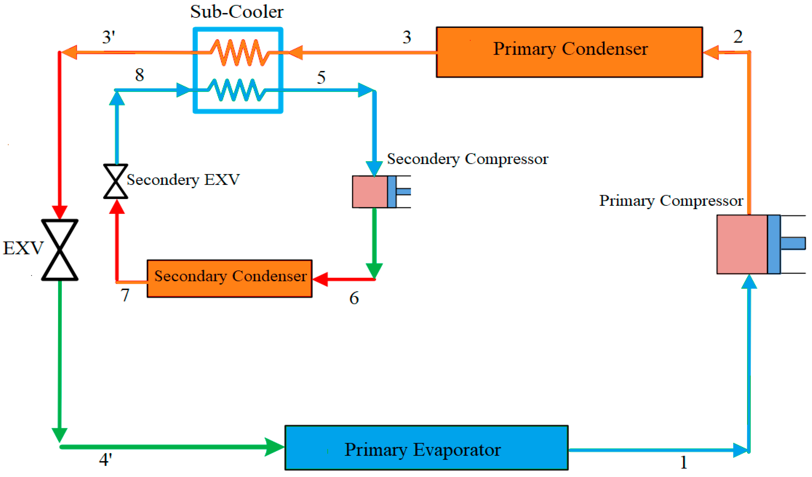
2.1.2. Mechanical Sub-Cooling (MS)

Mechanical sub-cooling aims to improve the cooling capacity using a small mechanical cooling system. As shown in Figure 5, the secondary cooling system cools down the refrigerant prior to the expansion stage to enhance the system’s efficiency. Thornton et al. [23] applied a mechanical cooling system to a supermarket refrigeration system and reported a 10% COP enhancement over a range of variables that were relevant to that particular application, which is remarkable; however, the authors did not discuss the feasibility of the proposed system over its lifetime. In another study, Khan and Zubair [24] investigated the effect of integrating mechanical sub-cooling after the condenser on the COP of the refrigeration cycle. They reported an improvement of 7.5% in the system COP. In 2012, Qureshi and Zubair [25] investigated the performance of different refrigerant combinations in the primary and sub-cooling refrigeration cycles with mechanical subcooling. The authors of this study concluded that the best COP was achieved when R-134a was used in the primary cycle, but more refrigerants could be tested in the future to find the best combination. She et al. [26] applied an expander in order to drive the sub-cooling refrigeration cycle, which yielded a 19% improvement in the primary cycle COP compared to conventional mechanical sub-cooling. In addition, the study proposed R-744 for the primary cycle and R-12 for the sub-cooling cycle. However, due to the high ODP of the R-12, other refrigerants could be used as more environmentally friendly options, including HFOs or natural refrigerant options.
In a recent study, the CO2, N2O, and ethane performance were tested with dedicated mechanical sub-cooling. The study showed that mechanical sub-cooling improved the cycle performance for all refrigerants, and the best improvement was for ethane (36.1%), then CO2 (30.74%) [27].
Chen et al. [28] studied the effect of increasing the cooling capacity and subcooling power on the mechanical sub-cooling vapor compression cycle. The ratio of the cooling capacity improvement to the subcooling power was studied experimentally. This ratio was found to be in the range of 7.5% to 50% depending on the cycle parameters, such as secondary cycle power, chilled water flow rate and compressor speed.

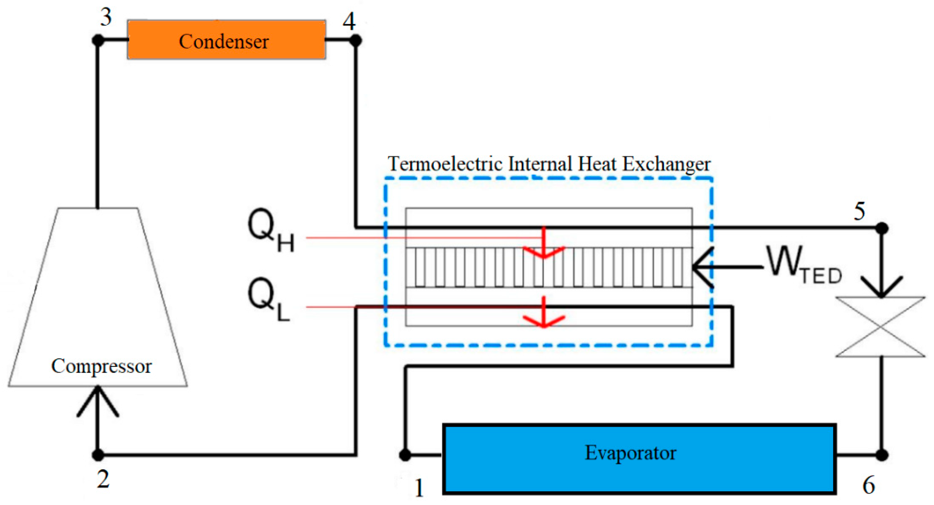
2.1.3. Thermoelectric Sub-Cooling (TS)

A thermoelectric system is a device that works on the Peltier effect and can convert electricity directly to the temperature difference without any moving parts, which makes it extremely reliable. However, its application is very limited due to its relatively low energy efficiency, especially when used with high-temperature lifts. Figure 6 shows a schematic diagram of a vapor compression cycle with thermoelectric internal heat exchanger.
Winkler et al. [29] carried out a simulation project to investigate the effect of using a thermoelectric sub-cooler on the performance of R-744 refrigeration systems and reported improvements of 20% and 16% in the system cooling capacity and COP, respectively.
Radermacher et al. [30] conducted a theoretical study to compare the improvement in the COP of a single-stage thermoelectric sub-cooler and a double-stage thermoelectric sub-cooler. The study reported a better COP enhancement by using the double-stage thermoelectric sub-cooler. However, the feasibility and the added complexity of the double-stage thermoelectric subcooling compared to the single one were not discussed.
Schoenfeld et al. [31] investigated the improvement in performance of R-744 systems using a thermoelectric sub-cooler via an experimental model. The study reported a 7.9% capacity improvement and increase of 3.3% for the COP using a controlled thermoelectric hybrid system.
To optimise R-744 refrigeration systems coupled with a thermoelectric sub-cooler, Sarkar [32] carried out a simulation study with exergy and energy analysis. The study reported that by using thermoelectric sub-cooling, it was possible to improve the system COP and reduce the cycle high-side pressure and, hence, the compressor pressure ratio, which directly relates to the compressor power consumption. Accordingly, it could reduce the compressor power.
In a recent study, Kwan et al. [33] applied a thermoelectric heat exchanger to the trans-critical cycle to increase the cycle’s coefficient of performance (COP); it was studied as a thermoelectric generator to generate additional electricity from the internally exchanged heat and as a thermoelectric cooler to accelerate the internal heat transfer rate. Simulation results showed that although operating the device as a thermo-electric generator offered a COP improvement of up to 5%, the improvement was inferior to the direct thermoelectric cooling option. This occurred because the device’s thermal resistance lowered the heat transfer effectiveness. Moreover, operating as a thermoelectric cooler significantly reduced the compressor power, but the device’s power consumption negates this benefit.
In research by Liu et al. [34], the performance of a CO2 ejector refrigeration system integrated with a thermoelectric sub-cooler was investigated via exergy analysis. The result of this study showed that 89.44% of the total exergy destruction was endogenous, with the highest avoidable exergy destruction in the compressor, then the thermoelectric sub-cooler, followed by the evaporator, the ejector, and the gas cooler. According to new experimental research testing the real trans-critical R-744 VCC with a thermoelectric sub-cooler, the COP increased by 11.3% and the capacity increased by 15.3% when using a sub-cooler supplied with 2 V and a fan supplied with 9 V [35].

2.2. Cycle Improvement by Expansion Loses Recovery

In the refrigeration cycle, various expansion devices, including capillary tubes, orifices, thermostatic expansion valves, or electronic expansion valves, are commonly used to expand the refrigerant to lower its pressure. Theoretically, this process should be isenthalpic, meaning enthalpy should be reserved. However, in reality, the expansion process wastes energy that can be recovered by using expanders or ejectors [36].

2.2.1. The Expander Cycle

The expander is a small device that is similar to the compressor principle in reverse. It is used to expand the refrigerant and convert the recovered energy of the expansion process into kinetic energy that can be used for different purposes; one of these purposes is to improve the system COP and the cooling capacity. A schematic of the expander cycle is shown in Figure 7.
Huff et al. [37] carried out a study to investigate the effect of using a positive displacement expander on the performance of the R-744 refrigeration cycle. The authors reported an improvement of 40–70% in the COP and 5–15% in the system cooling capacity. Nickl et al. [38] investigated the performance of a CO2 refrigeration system with a three-stage expander. The study reported an improvement in the system COP of more than 40%. In addition, the main compressor discharge pressure was lowered. Wang et al. [39] carried out a simulation project using a two-stage vane-type expander in an R-410A refrigeration system, and the reported COP improvement for this study was 14.2%. Subiantoro and Ooi [40] conducted an economic analysis on a medium-scale air conditioner vapor compression cycle with an expander, assuming 50% expander isentropic efficiency and 75% compressor isentropic efficiency. The study suggested different cycle configurations and showed a payback period of around 5 years for all of the proposed options.
Hu et al. [41] tested an improved expander in a CO2 water-to-water heat pump system. The experimental results showed that the revised expander had a higher efficiency than the primary one, reaching a maximum of 77% at the revolution speed of 867 rpm and a maximum recovered expansion work of 242 W at the revolution speed of 770 rpm. However, further improvements in the expander were recommended because the measured parameters of the prototype were not close to the design values.

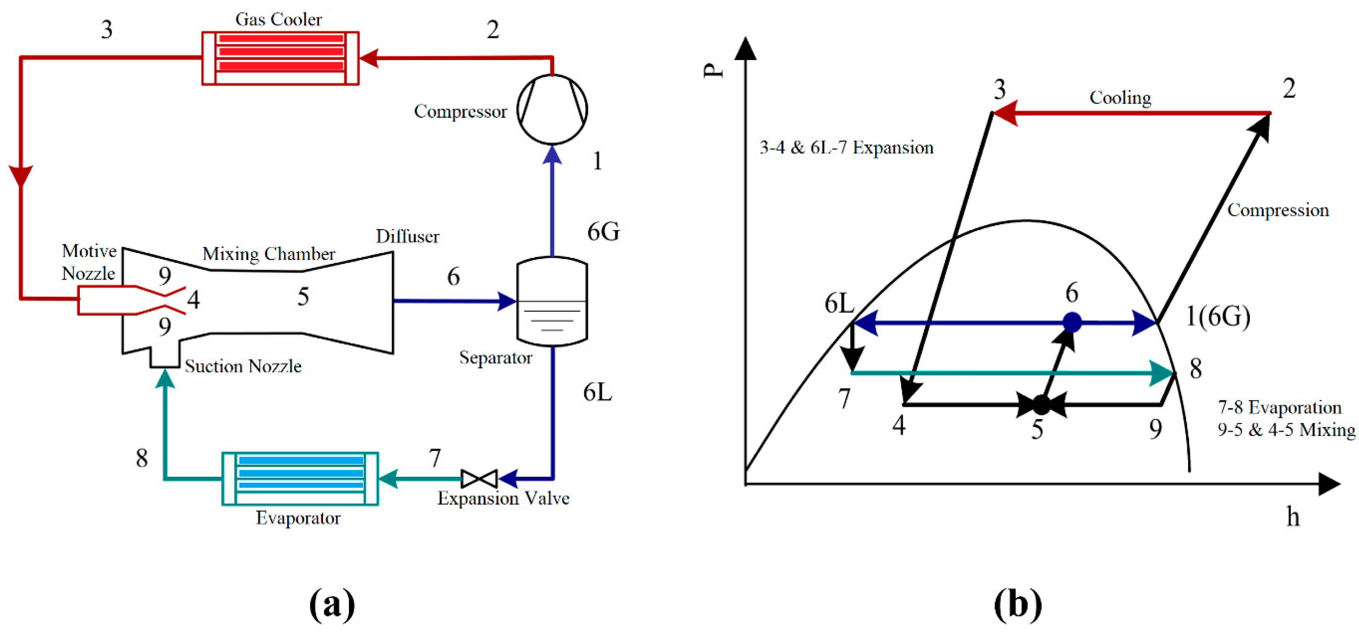
2.2.2. Ejector Cycle

The ejector consists of a mixing chamber, nozzle, and diffuser. The ejector’s main function is to mix refrigerant from the high-pressure side with the refrigerant from the low-pressure side. When the refrigerant flows from the condenser through the ejector and past the nozzle, the pressure drops, and it draws the refrigerant from the evaporator outlet; both the low and the high-pressure streams mix in the mixing chamber, and the diffuser recovers the energy of the mixed fluid.
Disawas and Wongwises [42] investigated the effect of the condenser and evaporator operation temperatures on the performance of the ejector-based expansion refrigeration cycle. The authors reported a lower COP improvement with an increasing condenser temperature for R-134a refrigerant. However, the compressor discharge temperature and the pressure ratio were lower than a conventional VCC. In another study, a similar conclusion was drawn by Li and Groll in 2005 in their study on the CO2 refrigeration cycle, as they found that the improvement in the COP of the ejector-based cycle was more than 16% compared to a conventional VCC. However, they reported that the ejector-based cycle performance was very sensitive to the separator performance [43].
One of the ejector types is a two-phase ejector in which the refrigerant at the condenser outlet is split into two streams. One stream is sent to the ejector nozzle, and the other one is passed through an isenthalpic throttling process and sent to the evaporator. The second evaporator is fed with the mixed refrigerants coming from the ejector mixing chamber [44]. In another study, Boumaraf et al. [45] investigated the performance of a two-phase ejector through simulation for both R-134a and R-1234yf and compared the results to a conventional VCC. The study showed a COP improvement of more than 17% at a 40 °C condenser temperature for both refrigerants, with better improvement values for R1234yf, especially at elevated condenser temperatures. However, R-134a showed higher COP values for both cycle options. Lawrence and Elbel [46] experimentally investigated the performance of the two-phase ejector cycle for R-1234yf and R-134a refrigerants. The authors reported that the two-phase ejector showed higher COP improvement values for R-1234yf, with 12% compared to 8% for the R-134a against cycles with expansion valves; this result shows that the ejector cycle efficiency is dependent on the refrigerant properties. Hafner et al. [47] investigated the performance of the R-744 supermarket refrigeration system with ejectors. The study reported COP enhancements of 5–17% for cooling and 20–30% for heating.
In order to reduce the throttling loss in the CO2 refrigeration cycle, Zhang and Tian [48] investigated the potential COP improvement observed when using an ejector to replace the throttle valve, and they developed a thermodynamic model of the transcritical CO2 ejector expansion cycle (Figure 8a). The maximum COP of this model was found to be 45.1% higher compared to the basic cycle. In addition, the exergy loss was 43.0% less than the basic cycle.
Jeon et al. [49] conducted a study to investigate the effects of ejector geometries on the performance of a small-sized R-600 refrigeration under different operating conditions. The performance of the condenser outlet split ejector cycle was measured and analysed by varying the compressor speed, entrainment ratio, nozzle position, and mixing section diameter. It was found that the expansion loss was reduced by decreasing the entrainment ratio and increasing the compressor speed. At a compressor speed of 45 Hz and an entrainment ratio of 0.3, the maximum improvement in the COP of the condenser outlet split ejector cycle with the optimum mixing section diameter, over that of the baseline cycle, was 6.8%. In addition, the optimum mixing section diameter for a given ER and compressor speed was proposed.
The previous studies show that using an ejector in the refrigeration cycle is a promising technique that can help to enhance the cycle coefficient of performance. However, its impact on the cycle depends on the refrigerant properties and the cycle operating temperatures. Accordingly, more research is required in this area to find the optimal cycle parameters and refrigerant that can achieve optimal performance.

3. Refrigerants Development and Environmental Assessment

Refrigerants are used to absorb and transfer heat between space and the surrounding environment, mainly through vapor compression-based equipment. Most of these refrigerants are volatile and contain gases that affect the environment through their heat-trapping capacity or their global warming potential (GWP). Moreover, many of these refrigerants impact the ozone layer (ODP) [50]. The refrigerants used in most current systems, such as R134a and R410, have either no or a very low ODP. However, they still have a high GWP, which could last for 100 years for some refrigerants. Hence, they are expected to be phased out of the market in the next decade. The HVAC industry has undergone three main stages based on the refrigerant selection criteria.
The initial stage started with the invention of VCC systems and lasted until the late 1920s, when mainly natural materials such as ammonia, carbon dioxide, hydrocarbons, sulphur dioxide, chloroethene, air, ether, and methyl chloride were used as refrigerants. Then, with the invention of freon in 1930, the market shifted toward the vast adoption of halogenated compounds known as chlorofluorocarbons (CFCs). These provided solutions for toxicity, flammability, and odour compared to the previous refrigerants, and they were marketed at that time as a safer and more efficient option before the subsequent discovery that CFCs represent a severe threat to human life through their direct relation to the depletion of the ozone layer. The environmental impact of CFCs was discovered 50 years after introducing them, leading to an international decision to phase out CFCs in the Montreal Protocol of 1987 [51]. In 2017, the Montreal Protocol issued the EDGE Document; this document set out a compulsory phase-out timeline for CFCs. According to this agreement, the timeline must be reviewed regularly to expedite the phase-out process. This collaborative work introduced hydrofluorocarbons (HFCs) as a replacement for CFCs [52].
In order to reduce the environmental impact of refrigerants, some restrictions on the use of HCFCs, also known as freons, were suggested due to their GWP. Furthermore, the Paris Agreement of 2015 set a framework through which to limit global warming and keep it below 2 °C. The Kigali amendment of the Montreal Protocol was agreed upon in 2016; this agreed to phase out HFCs with a high GWP and called for an 85% reduction in GWP-weighted products in developed countries by 2036, with later phase-down dates for other countries.
FICs (Fluoroiodocarbons) were introduced in the nineties as a replacement option for CFCs; these refrigerants are not available in nature but are produced in special manufacturing facilities via a chemical reaction. One example of an FIC is CF3I. Generally, FICs decay photolytically in the visible light spectrum, resulting in a limited atmospheric lifetime, which is estimated to be 1.15 days. The ODP of these refrigerants is very low and is estimated to be around 0.009 based on a 5% leakage allowance [52].
The most promising replacement for the current refrigerants are the hydroflouroolefins (HFOs). These refrigerants have global warming potential but have a very short atmospheric lifetime compared to HFCs. Some of these refrigerants are toxic, and others are flammable, but HFO-1234yf is difficult to ignite and has an unstable flame. Thus, it is widely used in automotive air-conditioning systems and is expected to replace the R-134a refrigerant soon for this particular application [53]. HFO-1234ze(E) and HFO-1336mzz(Z) are non-flammable, have a low toxicity, and are more suitable for chiller applications. Development is also ongoing for some other HFOs, such as HFO-1132a, which has a relatively low boiling temperature of −83 °C, and HFO-1123, which one manufacturer has proposed as a replacement for R-410a. However, the use of this refrigerant is not always appropriate at a high pressure and temperature, and the company claims that risks could be mitigated by blending it with R-32 [54]. Hydrochlorofluoroolefins (HCFOs) are a new refrigerants group that contains fluorine and chlorine; this group has a relatively low GWP and a negligible ODP. HCFOs have been promoted as chiller-suitable refrigerants with a very short atmospheric lifetime.
A good example is HCFO-1233zd(E), which has an ODP < 0.0004. Another refrigerant from the same group still under investigation is HCFO-1224yz(Z) [55]. The Table 1 shows the refrigerant types and their current technological status.
Some researchers have tried to investigate HFO/HFC blends. Yu et al. [56] theoretically investigated the air-conditioning and heat pump cycle performance of some HFC/HFO mixtures. The tested blends had medium flammability (A2L) with a GWP value below 150. The blends used that were based on mass fraction were R-1123/R-161/R-13I1 (65/5/30), R-1123/R-152a/R-13I1 (65/5/30) and R-1123/R-1234ze(E)/R-13I1 (65/5/30). All of these blends achieved a GWP that was lower than 10. However, none of them achieved a high COP compared to the R-410a baseline.
As the condensing temperature increases, the volumetric heating capacity of the R-1234yf reduces sightly. This HFO presents a higher volumetric heating capacity at the highest temperatures, indicating that this refrigerant is more suitable for high-condensing-temperature heat pump applications. However, some researchers have questioned the replacement of the current refrigerants with HFOs and have raised concerns regarding the safety of the decomposition of these refrigerants in the case of fire, as they can produce highly toxic substances. Moreover, these refrigerants could be very harmful to the ecosystem, as there is an inherent risk represented by the increase in the acidity of the environment resulting from the breakdown of these refrigerants into trifluoroacetic acid [57].
For any substance to be used as a refrigerant, it must satisfy a set of thermodynamic, thermophysical, chemical, and environmental requirements. Thermodynamic and thermophysical properties, such as the thermal capacity, normal boiling temperature, density, thermal conductivity, and viscosity, dictate the efficiency of the refrigeration cycle. The main thermodynamic property that influences the selection of any refrigerant is its normal boiling temperature, as this is directly related to the system’s operating pressure and the critical temperature of the refrigerant, which dictates the system’s operating temperature. These properties influence the system COP and volumetric efficiency, since refrigerants with high critical temperatures commonly have a higher COP but a lower volumetric efficiency [58]. In addition, the refrigerant’s thermal capacity and latent heat of vaporisation affect the system efficiency. The efficiency of the system’s heat exchangers is highly related to the refrigerant’s thermophysical properties, as they affect the system’s energy intensity and account for the system’s irreversibility losses [59]. Another aspect that has to be considered in refrigerant selection is the refrigerant’s chemical properties, which directly relate to the system’s operating safety. These properties include its interaction with the system components and lubrication oil. Furthermore, other critical refrigerant properties include their flammability, explosivity, and breakdown temperature-decomposition temperature. A refrigerant with a higher decomposition temperature than the maximum system operation temperature should be selected [60].
The refrigerant’s interaction with the environment and its physiological properties are essential aspects driving the industry nowadays, as refrigerants are one of the leading causes of ozone depletion; thus, they need to be selected with a comprehensive environmental assessment [61]. Previous studies have revealed that some systems, such as mobile air conditioners and large refrigeration systems, could leak up to 30% of their refrigerant capacity yearly. Thus, they need to be as least environmentally harmful as possible. In addition to global warming potential, the TEWI (Total Equivalent Warming Impact) is another index that combines both the GWP of the refrigerant and the estimated amount of CO2 released from the power plant in order to supply these systems with power throughout their lifetime [62]. The LCCP, or life-cycle climate performance, is similar to the TEWI with more accuracy, and is more complicated. However, it indicates the refrigerant’s direct and indirect impacts on global warming over the lifetime of the refrigeration system, including expected refrigerant leaks [63].
Refrigerant flammability is an important aspect that influences the refrigerant suitability of any system and identifies the practical refrigerant limits of operation. The classifications used in the industry for refrigerant flammability are the lower flammability limit (LFL), the burning velocity and the heat of combustion (HOC). The last environmental consideration is refrigerant toxicity, which is standardised in the industry as a 400 ppm occupational exposure limit; this is a defining point between low and high-toxicity refrigerants.
McLinden et al. [64] carried out a study to find new refrigerants via a systematic approach. The study mainly focuses on assessing the candidate refrigerants’ thermodynamic properties and environmental impact. The study concluded that low GWP options were limited, and most were slightly flammable. Hence, compromises must be considered when selecting the next generation of refrigerants.

3.1. Natural Refrigerants

Natural refrigerants are substances that are available in the environment and have been used in different refrigeration applications since the early nineties. Many of these refrigerants have a negligible or no effect on global warming or ozone depletion. However, they have some disadvantages related to safety and engineering due to their chemical and physical properties.
For instance, water (R-718) has good thermal properties but a very high specific volume in the vapour state and has a high normal boiling temperature, complicating the system design, operation, and cost. Ammonia (R-717) is a sound refrigerant due to its thermodynamic and thermophysical properties, allowing for a wide operating temperature range. However, it is toxic in high concentrations. Hence, the use of ammonia in vapor compression systems is limited to large industrial systems. Carbon dioxide (R-744) works on a relatively high pressure and needs the system to be designed and engineered with special considerations [65]. Hydrocarbons such as propane (R-290) and isobutane (R-600) are the most used refrigerants among all the natural refrigerants [66]. However, they are flammable and extra safety precautions must be taken when using them. Other hydrocarbons have good thermodynamic properties that are suitable for refrigerants, such as ketones, alcohols, and alkanes [51,67]. Among these, alkanes are preferred, even though they are flammable [68]. Many hydrocarbons, such as propane and isobutane, have been used in refrigeration in both commercial and domestic applications [66]. However, due to their high flammability, they must be highly miscible with lubricants throughout the entire operating range, and most pure hydrocarbons are stable with water [60]. Hence, hydrocarbon refrigeration systems are designed with a positive evaporator pressure in order to prevent humid air from entering the system. Below is a description of the natural refrigerants and their applications. Table 2 shows the properties of some common natural refrigerants compared to R-134a.

3.1.1. Air

Air offers many advantages as a refrigerant, such as safety, availability, and being environmentally friendly. Air-based refrigeration systems work on the Joule or reverse Brayton cycle, by which air is heated and cooled via compression and expansion. Air-based air conditioning systems are not energy efficient. However, they are commonly used in airplane cabin air-conditioning systems as compressed air is already available from the engine. With the development of compressors, expanders, and compact heat exchangers, air-based cooling systems are becoming more efficient and are comparable to conventional refrigerants [69,70].

3.1.2. Water (R-718)

Water has some attractive properties as it is environmentally friendly with an ODP of 0 and a GWP of less than 1, which is rare for refrigerants. In addition, it is available in massive quantities, has excellent thermodynamic properties, such as a high latent heat of vaporisation and thermal capacity, and is chemically stable, non-toxic, and non-flammable, which satisfies safety requirements [8].
Despite all these advantages, using water as a refrigerant requires working with extremely low operating pressures, which adds challenges in terms of the large specific volume of water vapor, which requires a high volumetric flow rate and, thus, large compressors [71]. Moreover, it requires a high-pressure ratio and, as a result, special compression arrangements or multi-stage compression to run the system in the same temperature range as other refrigerants being used in the industry. Water has been used in refrigeration for years and in many applications, most commonly in evaporative cooling and absorption chillers. However, its utilisation in the vapor compression cycle has been limited due to its unfavourable thermo-physical properties.

3.1.3. Hydrocarbons

Hydrocarbons consist of pure hydrogen compounds and are considered a viable option for refrigeration due to their suitability for cooling, low environmental impact, and energy efficiency. However, hydrocarbons are highly flammable at high pressures. At the same time, to generate a flame, refrigeration hydrocarbons must be mixed with the right amount of air in the presence of greater than 0.25 J and a 713 °K ignition source, which is not commonly available in real-life conditions [72]. According to the Environmental Protection Agency (EPA), special measures should be taken to design and operate hydrocarbon refrigeration systems; this would include placing limitations on the operating pressure range, eliminating potentially fire-starting sources, and ensuring the highest safety measures, such as reducing the amount of refrigerant used by employing more efficient heat exchangers. The current hydrocarbons that are used as refrigerants include methane, ethane, propane (R-290), ethylene (R-1150), n-butane (R-600), isobutane (R-600a), propylene (R-1270), pentane (R-601) and others. Hydrocarbons have attracted more attention in recent years, driven by growing environmental awareness. Their applications include small charge systems, mobiles, truck refrigeration, and small tonnage chillers with a cooling capacity below 150 kW [8].

3.1.4. Carbon Dioxide (R-744)

Carbon dioxide is considered one of the most promising natural refrigerants due to its safety and environmental advantages. The EPA classifies it as an A1 refrigerant, which defines the least hazardous and toxic category. For these reasons, carbon dioxide is considered a viable option for large-scale refrigeration plants, although leaks could be a concern. In addition, other factors that have led to carbon dioxide being used in many refrigeration systems since 1850 are its availability and low cost compared to other refrigerants [16]. The main challenge facing the wider adoption of carbon dioxide as a refrigerant is its requirement of an extremely high pressure, around 200 atmospheres, to condense, which may lead to extra costs associated with designing a system that can withstand high pressure. However, in recent years, R-744 has attracted more attention in cascade refrigeration due to its applicative potential in the lower temperature cycle [68].
In new research, Nebot-Andrés et al. [73] conducted an experimental study to determine the optimum working conditions of a CO2 refrigeration system integrated with mechanical sub-cooling. In order to extract the system COP, different operating pressures and sub-cooling conditions were tested. The study concluded that the optimum ambient temperatures were 25.0 °C, 30.4 °C and 35.1 °C, and a −15.6 °C to −4.1 °C evaporation temperature.

3.1.5. Ammonia (R717)

Ammonia (NH3) has been used in refrigeration since 1872 [7]. Ammonia has attracted popularity due to its thermodynamic properties, including efficiency, availability, low cost, and low environmental impact. In addition, ammonia has a high latent heat of vaporisation and requires a low flow rate. Hence, it is commonly used in large refrigeration systems. One of the significant issues of ammonia is its toxicity, but with proper safety arrangements and emergency protocols, this risk can be managed. Ammonia has a smell that allows humans to detect leaks at a concentration as low as 5 ppm, while it is not technically toxic below 300 ppm.
Moreover, it does not cause any health effects unless the exposure continues for more than 30 min. Furthermore, ammonia is classified as an A2L low-flammability refrigerant by ASHRAE. As a result, and with growing awareness regarding ammonia safety arrangements, the use of ammonia is expected to increase in the near future. Table 3 shows the natural refrigerants applications, advantages and disadvantages.

3.2. Water as a Refrigerant

As mentioned in Section 1, using water as a refrigerant is not a new idea, and it was used for the first time in 1934 in an air-conditioning system produced by Belmont. However, due to unfavourable thermophysical properties, water was gradually removed from the market, especially with the development of other refrigerants that made the systems more compact and economical [9]. Table 4 shows the advantages and disadvantages of water as a refrigerant.
Researchers have investigated different solutions for water-based refrigeration cycles, driven by growing environmental awareness. Some have aimed to find a solution for the high compressor discharge temperature associated with the high compression ratio required in the water vapor refrigeration cycle. Some have focused on enhancing the system efficiency via different means [74]. Meanwhile, other studies have been conducted on different compressors, such as centrifugal, screw, axial, reciprocating and root, in order to find the best type of compressor or technique that can be applied to make the system more attractive for cooling industry applications [74]. Orshovn et al. [67] investigated the potential and limitations of water as a refrigerant in refrigeration and heat pump applications. The study showed that water as a refrigerant might be more viable if used as a refrigerant and heat transfer medium in the same system, such as in ice production applications. However, more research on water vapor compression is required in order to reduce the compressor diameter in the case of centrifugal compressors.
The Institut für Luft- und Kältetechnik (Institute of Air Handling and Refrigeration) (ILK) has performed multiple studies on vapor compression refrigeration systems with R-718; these were used to build the first chiller with a dual-stage turbo compressor in 2000. The cooling capacity of their chillers ranged between 500 kW and 1000 kW, with an evaporator temperature of 4–10 °C.
To overcome the challenges associated with water vapor compression, both centrifugal and axial turbo compressor types were tested by the Air-Conditioning and Refrigeration Technology Institute (ARTI); the project aimed to determine the optimal compressor size for a 3700 kW cooling capacity. The results showed that in the case of the two-stage centrifugal compressor, an rpm of 5490, impeller and housing diameters of 2.49 m and 5.4 m, respectively, and a compressor isentropic efficiency of 77.4% were needed to achieve a 6.8 compression ratio and a 6.6 °C evaporator temperature. On the other hand, a 3.2 m long axial compressor with a 1.3 m diameter and 82% efficiency could achieve the same cooling capacity with a 6600 rpm compressor speed, making it a better option for water vapor refrigeration applications [75].
Yuan et al. [76] studied the effect of changing the evaporator and condenser temperatures on the COP of water vapor compression refrigerators. They reported that R-718 could be suitable for replacing CFCs and HCFCs, especially for high-evaporator-temperature or low-temperature lift systems. Kharazi et al. [25,26,27,28,29] studied and implemented the combination of a three-port condensing wave rotor and centrifugal compressor. This study focused on the R-718 refrigeration cycle and aimed to reduce the pressure ratio and compressor discharge temperature. The study concluded that by using this technique, a 22% COP improvement was achieved. Figure 9 shows a schematic of the proposed cycle.
A comparative study of water as a refrigerant with other refrigerants was conducted by Kilicarslan et al. [51]. Their results showed a higher COP of the water system compared to R-134a, R-290 and R-22 for high evaporation temperatures. However, the use of water vapor showed various disadvantages, such as a high compressor pressure ratio, a high vapor specific volume, and a high compressor discharge temperature. These technical challenges could be addressed by designing special compressors to cover more applications. In another study, the economic feasibility of the R-718 chiller was investigated by Lachner et al. [74]. In this study, component-level models were used to determine the performance of a 3700-kW chiller by simulating different system variables and different configurations. The economic terms of the system, such as capital cost, operating cost, and the payback period, were estimated. It was concluded that with the available technology at the time of the study, the R-718 chiller was not feasible compared to chillers using other refrigerants. However, a direct contact condenser was recommended to increase efficiency.
Alexis [77] investigated the irreversibility of the steam-ejector refrigeration system via exergy analysis in order to evaluate the factors affecting the system performance. The study concluded that the main part that affects the cycle performance is the ejector, followed by the compressor, as these two components have the most significant exergy losses among all the cycle components. The cycle considered a condenser temperature of 44–50 °C and an evaporator temperature of 4–8 °C. This study did not consider the performance of the water vapor refrigeration cycle against other refrigerants and whether other cycles would lead to the same results. Jr et al. [74] conducted a study investigating the economic feasibility of a 3520 kW R-718 chiller. The study concluded that a double-stage centrifugal compressor and direct contact heat exchangers achieved the most feasible configuration. The most expensive part of the system was the compressor. Thus, developing a special high compression low-cost compressor is required for the future development of R-718 chillers. Sugawara et al. [78] investigated using the R-718 refrigerant in a small-capacity vacuum air-conditioning system with a centrifugal and reciprocating compressor. The COP reported from this study was around 1.0, which is very low compared to the VCC; the low COP could be caused by the use of an open cycle, which requires the system to operate between the very low pressure needed to vaporise the water at a low temperature and the relatively high pressure needed to overcome the atmospheric pressure, which may result in a very high-pressure ratio and, hence, a low COP.
Qubo et al. [79] proposed an impeller made of high-strength waved fibres to reduce the cost of the high-speed multi-stage axial compressor, as shown in Figure 10. The proposed impeller is made of composite material that can withstand a very high tip speed and can be manufactured at a relatively low cost compared with the current materials used to manufacture the blades of axial compressors. In this study, the authors proposed an improved cycle with flash intercooling between the stages, resulting in a 30% COP improvement at full load compared to the R-134a cycle.
In 2011, Sarevski and Sarevski [80] conducted a comparative analysis of an R718 heat pump and refrigeration systems. The study concluded that applying R718 in heat pumps and refrigeration systems is possible with centrifugal compressors and direct-contact heat exchangers. However, water vapor compression requires more effort to reduce the size and cost of the water vapor compressors. In 2011, Chamoun et al. conducted a comparative analysis of water vapor refrigeration and high-temperature heat pump systems with a condensing temperature of 130–140 °C; the same researchers designed and built the system in 2014. The study showed that direct evaporation and condensation heat exchangers could achieve the best performance.
Sarevski and Sarevski (2017) investigated the performance of applying a water vapor thermo-compression system in a heat pump application to find the optimal structure, then proposed an R-718 heat pump with a turbo compressor for a district heating application. The same authors investigated the effect of integrating a two-phase ejector on the performance of the water vapor refrigeration cycle. The system was designed with evaporation and condensation temperatures of 10 °C and 35 °C, respectively, and with a compression ratio of 4.58. The study concluded that using a two-phase ejector makes the R-718 system more feasible and increases the system’s capacity and energy efficiency [81].
Using R-718 in a mechanical vapor recompression system with a root compressor was applied by Zhang et al. [48]. In this application, the root compressor showed good stability. However, it showed many disadvantages, such as a low volumetric flow rate, limited pressure ratio, and a dramatic decrease in efficiency with an increasing pressure ratio. Other researchers presented a mathematical study on the effect of vapor injection on the root compressor performance in a water vapor refrigeration system. The study concluded that vapor injection could maintain the compressor exhaust temperature below 130 °C. In addition, when the injection ratio was maximised, the volumetric efficiency was increased, and as a result, the compressor power was minimized [82].
Kuhnl et al. [83] investigated the realisation of R718 chillers with flash cooling. The proposed system considered a direct contact condenser and a chilled water circulation loop through an evaporator. The study concluded that an R718 chiller with a direct contact condenser could achieve better performance than systems with other refrigerants due to the minimised temperature difference between the outlet and the inlet of the condenser. However, the size and cost of the compressor still represented a severe challenge in terms of commercialising the system; thus more work is required to build compressors that suit the water vapor compression applications. A thermodynamic assessment of using water as a refrigerant in cascade systems was conducted by Alkhulaifi et al. [84] through a mathematical model, in which the performance of the system e using R-718 was compared to other refrigerants. The authors reported that when using water, the COP improved by 2.9% to 8.6%, and that it was higher than other refrigerants, such as R41, R717, R290, and R1270.
W. Wu and Skye [85] conducted a comprehensive survey on a ground-sourced heat pump that uses CO2, NH3, water and hydrocarbons. The study considered the refrigerant’s thermodynamic properties, performance and recent progress. The authors studied the systems and evaluated water as a refrigerant for absorption-type ground-sourced heat pumps, including applications for solar cooling, ground imbalance, and district heating. The study concluded that water has excellent properties as a refrigerant. However, more work is needed to make it more feasible.
In 2020, Shoyama et al. [86] conducted an experimental study to develop a 100 kW heat pump with water as a refrigerant. This study investigated a new technique for using water-lubricated journal bearings. At the same time, cavitation control and a sprayed direct intercooler were applied. The authors concluded that a stable operation was achieved, with double compression and expansion at a COP of 5, similar to the latest heat pumps working on other refrigerants.
Shovon et al. [86] investigated the performance of different refrigerants in an ejector compressor-based solar thermal refrigeration system. This study considered a one-dimensional model with which to compare the refrigerant performance. The influence of the ejector area ratio, generator temperature, evaporator temperature, and condenser temperature on the performance shows that a higher coefficient of performance (COP) is associated with a higher ejector area ratio. The coefficient of performance increases by more than 74% when the refrigeration temperature is increased from Tc = 8 °C to Tc = 15 °C. The performance of the cycle using various refrigerants, such as R-717, R-718, R-245fa, R-123, R-141b and R-365fa, is calculated at the critical mode. With refrigerant R-717, the system shows a higher performance and better cooling effects than other refrigerants. However, the most environmentally benign refrigerant, R-718, shows a comparatively low performance, but it was found that R-718 produces a more significant cooling effect than other refrigerants, excluding the R-717 refrigerant.
Wu et al. [87] investigated the performance of six refrigerants, including water, in a high-temperature heat pump through simulation. The studied refrigerants were R-718, R-600, R-601, R-1234ze(Z), R-1336mzz(Z) and R-245fa. Among all refrigerants, R-718 achieved the best system performance and Carnot efficiency. The study concluded that R-718 could satisfy the high output temperature demand and performs better than most other refrigerants.
Shoyama et al. [88] proposed an R-718 turbo compressor with continuous cooling. This system sprayed water droplets into the impeller through an embedded nozzle to reduce the compressor discharge temperature. The study showed that the discharge temperature decreases as the flow rate increases. In addition, the COP increases with the spray flow to its peak value, but decreases with a further flow rate increase.

4. Conclusions

This research aims to help researchers that are interested in reducing the environmental impact of cooling systems used in buildings and presents the latest improvements in this technology in order to reduce its direct environmental impact by minimizing the energy consumption of cooling systems. At the same time, it presents suitable replacements for the current refrigerants to reduce the direct environmental impact of cooling systems. This study did not focus on the passive techniques that can also be used to reduce the cooling load or, in some cases, substitute the mechanical systems.
Vapor compression refrigeration systems significantly impact global warming both directly and indirectly. In addition, no better technology can replace the vapor compression cycle in the foreseeable future. Accordingly, reducing the environmental impact of the VCC is crucial. The points below provide a summary of this research:
  • The refrigeration cycle COP can be improved by increasing super-heating and sub-cooling or recovering expansion losses.
  • Sub-cooling and super-heating can be increased by using different methods, including suction line heat exchangers, mechanical sub-cooling, and thermo-electric sub-cooling.
  • The selection of the most suitable sub-cooling/super-heating method depends on the application and is highly related to the refrigerant properties.
  • Natural refrigerants are the ultimate solution for the environmental challenges of the VCC.
  • The most promising natural refrigerants are carbon dioxide and water, as they are the safest and most efficient among natural refrigerants.
  • Water is a very efficient and safe refrigerant, and could solve most of the environmental challenges related to refrigerants. However, more research is needed to solve the technical challenges associated with using water as a refrigerant.
  • The proposed solutions for using water as a refrigerant are as follows: promoting industry collaboration to reduce the cost of water compressors, using direct expansion and condensing techniques.
  • Using cascade refrigeration cycle and cycle modifications such as a two-phase ejector or expander could improve the refrigeration cycle performance. However, they are highly dependent on the refrigerant’s thermophysical properties, and detailed research should be performed to choose the most suitable technique.
This research provides an overview of the latest developments in vapor compression systems, including techniques that could be used to reduce energy consumption and an overview of refrigerants and natural refrigerants, with a focus on water. With further research on these subjects, the environmental impact of cooling systems could be minimised.

5. Future Prospects

Water can be considered as one of the most promising natural refrigerants. However, some challenges are holding back the broad utilisation of water in the refrigeration industry. These challenges can be summarised with the following points:
  • The high volumetric flow rate requirement driven by the very high specific volume of water vapor at low temperatures.
  • The relatively high pressure ratio that is needed for the system to operate within the evaporation and condensation temperatures commonly used for cooling applications.
  • The high compressor discharge temperature that results from the high compression ratio.
This study has highlighted some promising research areas that could make water more attractive as a refrigerant, including the use of composite material axial compressors, the integration of the cycle with a two-phase ejector, the use of direct evaporation and condensation heat exchangers, and the application of the cascade refrigeration cycle. In addition, by reducing the temperature lift between the low-pressure and high-pressure sides of the cycle, the R-718 cycle becomes more efficient and suitable for replacing the currently used refrigerants. Even though there are many disadvantages associated with using water as a refrigerant for cooling applications, it is still one of the best options and could offer environmentally friendly cooling. Since water represents an environmentally friendly option, it is recommended that researchers look for options that may reduce the impact of the technical challenges associated with using water as a refrigerant. Solving the technical challenges associated with water could include producing multi-stage compressors with lower prices and investigating new compressor options that are able to handle high-volume flow rates and compression ratios. In addition, these problems may be solved by looking for compressor blade material options that can withstand high temperatures and introducing new techniques that can lower the cycle temperature.

Author Contributions

Conceptualization, F.A. and M.S.I.; Literature Review, F.A.; Analysis, F.A.; Writing-original draft, F.A.; Writing-review and editing, M.S.I., N.S.B., S.C.S. and F.S.; Supervision, M.S.I., N.S.B. and S.C.S. All authors have read and agreed to the published version of the manuscript.

Funding

This research received no external funding.

Institutional Review Board Statement

Not applicable.

Informed Consent Statement

Not applicable.

Data Availability Statement

Data will be available upon request.

Conflicts of Interest

The authors declare no conflict of interest associated with this study.

Nomenclature

CFCChlorofluorocarbon
COPCoefficient of performance
FICFluoroiodocarbon
GHGGreenhouse gases
GWGlobal warming
GWPGlobal warming potential
HCFOHydrochlorofluoroolefin
HFCHydrofluorocarbon
HFOHydroflouroolefin
HVACHeating ventilation and air conditioning
MSMechanical sub-cooling
ODOzone depletion
ODPOzone depletion potential
SLHXSuction line heat exchanger
TSThermoelectric sub-cooling
VCCVapor compression cycle
VCRVapor compression refrigeration

References

  1. World—World Energy Balances: Overview—Analysis. (14 January 2021). IEA. Available online: https://www.iea.org/reports/world-energy-balances-overview/world (accessed on 14 December 2021).
  2. Energy Efficiency Requirements in Building Codes, Energy Efficiency Policies for New Buildings. (1 July 2008). IEA. Available online: https://www.iea.org/reports/energy-efficiency-requirements-in-building-codes-policies-for-new-buildings (accessed on 10 December 2021).
  3. Appendix: Compressive Refrigeration and the Heat Pump. In Air-Conditioning in Modern American Architecture, 1890–1970; Penn State University Press: University Park, PA, USA, 2021; pp. 237–240. [CrossRef]
  4. Heating and Cooling|Energy.gov.au. (13 December 2021). Available online: https://www.energy.gov.au/households/heating-and-cooling (accessed on 14 December 2021).
  5. Tang, R.; Wang, S.; Sun, S. Impacts of technology-guided occupant behavior on air-conditioning system control and building energy use. Build. Simul. 2020, 14, 209–217. [Google Scholar] [CrossRef]
  6. Rodriguez, J.; Fumo, N. Zoned heating, ventilation, and air–conditioning residential systems: A systematic review. J. Build. Eng. 2021, 43, 102925. [Google Scholar] [CrossRef]
  7. Wu, D.; Hu, B.; Wang, R. Vapor compression heat pumps with pure Low-GWP refrigerants. Renew. Sustain. Energy Rev. 2021, 138, 110571. [Google Scholar] [CrossRef]
  8. Savitha, D.; Ranjith, P.; Talawar, B.; Rana Pratap Reddy, N. Refrigerants for sustainable environment—A literature review. Int. J. Sustain. Energy 2022, 41, 235–256. [Google Scholar] [CrossRef]
  9. Siry, J.M. Air-Conditioning in Modern American Architecture, 1890–1970 (Buildings, Landscapes, and Societies), 1st ed.; Penn State University Press: University Park, PA, USA, 2022. [Google Scholar]
  10. Zhang, X.; Yang, W.; Shao, Z.; Li, Y.; Su, Y.; Zhang, Q.; Chengyi, H.; Wang, H. A Moisture-Wicking Passive Radiative Cooling Hierarchical Metafabric. ACS Nano 2022, 16, 2188–2197. [Google Scholar] [CrossRef]
  11. Lu, X.; Xu, P.; Wang, H.; Yang, T.; Hou, J. Cooling potential and applications prospects of passive radiative cooling in buildings: The current state-of-the-art. Renew. Sustain. Energy Rev. 2016, 65, 1079–1097. [Google Scholar] [CrossRef]
  12. Domanski, P.; Didion, D.; Doyle, J. Evaluation of suction-line/liquid-line heat exchange in the refrigeration cycle. Int. J. Refrig. 1994, 17, 487–493. [Google Scholar] [CrossRef]
  13. Preissner, M.; Cutler, B.; Radermacher, R.; Zhang, C. Suction line heat exchanger for R134a automotive air conditioning system. In Proceedings of the International Refrigeration and Air Conditioning Conference at Purdue Conference, Lafayette, IN, USA, 11–14 July 2000; pp. 289–294. [Google Scholar]
  14. Klein, S.R.; Reindl, D.T.; Brownell, K.A. Refrigeration system performance using liquid-suction heat exchangers. Int. J. Refrig. 2000, 23, 588–596. [Google Scholar] [CrossRef]
  15. Hwang, Y.; Huff, H.; Preissner, R.; Radermacher, R. CO2 transcritical cycles for high temperature application. In Proceedings of the 2001 ASME International Mechanical Engineering Congress, IMECE2001/AES-23630, New York, NY, USA, 11–16 November 2001. [Google Scholar]
  16. Cho, H.; Ryu, C.; Kim, Y. Cooling performance of a variable speed CO2 cycle with an electronic expansion valve and internal heat exchanger. Int. J. Refrig. 2007, 30, 664–671. [Google Scholar] [CrossRef]
  17. Cho, H.; Lee, H.; Park, C. Performance characteristics of a drop-in system for a mobile air conditioner using refrigerant. Korean J. Air Cond. Refrig. Eng. 2012, 24, 823–829. [Google Scholar]
  18. Navarro-Esbrí, J.; Molés, F.; Barragán-Cervera, Á. Experimental analysis of the internal heat exchanger influence on a vapour compression system performance working with R1234yf as a drop-in replacement for R134a. Appl. Therm. Eng. 2013, 59, 153–161. [Google Scholar] [CrossRef]
  19. Cho, H.; Lee, H.; Park, C. Performance characteristics of an automobile air conditioning system with internal heat exchanger using refrigerant R1234yf. Appl. Therm. Eng. 2013, 61, 563–569. [Google Scholar] [CrossRef]
  20. Pottker, G.; Hrnjak, P. Experimental investigation of the effect of condenser subcooling in R134a and R1234yf air-conditioning systems with and without internal heat exchanger. Int. J. Refrig. 2015, 50, 104–113. [Google Scholar] [CrossRef]
  21. Prabakaran, R.; Narayanaswamy, G.R.; Lal, D.M. Tuning thermostatic expansion valve for implementing suction line heat exchanger in mobile air conditioning system. J. Braz. Soc. Mech. Sci. Eng. 2019, 41, 191. [Google Scholar] [CrossRef]
  22. Mahdi Al-Obaidi, A.S.; Naif, A.; Al-Harthi, T.K. Optimisation of the performance of vapour compression cycle using liquid suction line heat exchanger. J. Therm. Eng. 2020, 6, 201–210. [Google Scholar] [CrossRef]
  23. Thornton, J.; Klein, S.; Mitchell, J. Dedicated mechanical subcooling design strategies for supermarket applications. Int. J. Refrig. 1994, 17, 508–515. [Google Scholar] [CrossRef]
  24. Khan, J.U.R.; Zubair, S.M. Design and rating of dedicated mechanical-subcooling vapour compression refrigeration systems. Proc. Inst. Mech. Eng. Part A J. Power Energy 2000, 214, 455–471. [Google Scholar] [CrossRef]
  25. Qureshi, B.A.; Zubair, S.M. The effect of refrigerant combinations on performance of a vapor compression refrigeration system with dedicated mechanical sub-cooling. Int. J. Refrig. 2012, 35, 47–57. [Google Scholar] [CrossRef]
  26. She, X.; Yin, Y.; Zhang, X. A proposed subcooling method for vapor compression refrigeration cycle based on expansion power recovery. Int. J. Refrig. 2014, 43, 50–61. [Google Scholar] [CrossRef]
  27. Miran, A.Z.; Nemati, A.; Yari, M. Performance analysis and exergoeconomic evaluation of a TRC system enhanced by a dedicated mechanical subcooling. Energy Convers. Manag. 2019, 197, 111890. [Google Scholar] [CrossRef]
  28. Chen, E.; Li, Z.; Yu, J.; Xu, Y.; Yu, Y. Experimental research of increased cooling output by dedicated subcooling. Appl. Therm. Eng. 2019, 154, 9–17. [Google Scholar] [CrossRef]
  29. Winkler, J.; Aute, V.; Yang, B.; Radermacher, R. Potential benefits of thermoelectric elements used with air-cooled heat exchangers. In Proceedings of the International Refrigeration and Air Conditioning Conference at Purdue Conference, R091, West Lafayette, IN, USA, 17–20 July 2006. [Google Scholar]
  30. Radermacher, R.; Yang, B.; Hwang, Y. Integrating alternative and conventional cooling technologies. ASHRAE J. 2007, 49, 28–35. [Google Scholar]
  31. Schoenfeld, J.; Hwang, Y.; Radermacher, R. CO2 transcritical vapor compression cycle with thermoelectric subcooler. HVAC&R Res. 2012, 18, 297–311. [Google Scholar]
  32. Sarkar, J. Exergy analysis of vortex tube expansion vapour compression refrigeration system. Int. J. Exergy 2013, 13, 431. [Google Scholar] [CrossRef]
  33. Kwan, T.H.; Shen, Y.; Wu, Z. Performance analysis of the thermoelectric device as the internal heat exchanger of the trans-critical carbon dioxide cycle. Energy Convers. Manag. 2020, 208, 112585. [Google Scholar] [CrossRef]
  34. Liu, X.; Yu, K.; Wan, X.; Li, X. Performance evaluation of CO2 supermarket refrigeration system with multi-ejector and dedicated mechanical subcooling. Energy Reports. 2021, 7, 5214–5227. [Google Scholar] [CrossRef]
  35. Aranguren, P.; Sánchez, D.; Casi, A.; Cabello, R.; Astrain, D. Experimental assessment of a thermoelectric subcooler included in a transcritical CO2 refrigeration plant. Appl. Therm. Eng. 2021, 190, 116826. [Google Scholar] [CrossRef]
  36. Sharma, D.; Sachdeva, G.; Saini, D.K. Optimised Refrigerant Flow Rate and Dimensions of the Ejector Employed in a Modified Ejector Vapor Compression System. Int. J. Air-Conditioning Refrig. 2020, 28, 2050038. [Google Scholar] [CrossRef]
  37. Huff, H.; Linsay, D.; Radermacher, R. Positive displacement compressor and expander simulation. In Proceedings of the International Compressor Engineering Conference at Purdue Conference, C9-2, West Lafayette, IN, USA, 16–19 July 2002. [Google Scholar]
  38. Nickl, J.; Will, G.; Quack, H.; Kraus, W. Integration of a three-stage expander into a CO2 refrigeration system. Int. J. Refrig. 2005, 28, 1219–1224. [Google Scholar] [CrossRef]
  39. Wang, M.; Zhao, Y.; Cao, F.; Bu, G.; Wang, Z. Simulation study on a novel vane-type expander with internal two-stage expansion process for R-410A refrigeration system. Int. J. Refrig. 2012, 35, 757–771. [Google Scholar] [CrossRef]
  40. Subiantoro, A.; Ooi, K.T. Economic analysis of the application of expanders in medium scale air-conditioners with conventional refrigerants, R1234yf and CO2. Int. J. Refrig. 2013, 36, 1472–1482. [Google Scholar] [CrossRef]
  41. Hu, J.; Li, M.; Li, H.; Xia, B.; Ma, Y. Improvement and experimental research of CO2 two-rolling piston expander. Energy 2015, 93, 2199–2207. [Google Scholar] [CrossRef]
  42. Disawas, S.; Wongwises, S. Experimental investigation on refrigeration cycle performance using a two-phase ejector as an expansion device. Int. J. Refrig. 2004, 27, 587–594. [Google Scholar] [CrossRef]
  43. Li, D.; Groll, E.A. Transcritical CO2 refrigeration cycle with ejector-expansion device. Int. J. Refrig. 2005, 28, 766–773. [Google Scholar] [CrossRef]
  44. Lawrence, N.; Elbel, S. Theoretical and practical comparison of two-phase ejector refrigeration cycles including First and Second Law analysis. Int. J. Refrig. 2013, 36, 1220–1232. [Google Scholar] [CrossRef]
  45. Boumaraf, L.; Haberschill, P.; Lallemand, A. Investigation of a novel ejector expansion refrigeration system using the working fluid R134a and its potential substitute R1234yf. Int. J. Refrig. 2014, 45, 148–159. [Google Scholar] [CrossRef]
  46. Lawrence, N.; Elbel, S. Experimental investigation of a two-phase ejector cycle suitable for use with low-pressure refrigerants R134a and R1234yf. Int. J. Refrig. 2014, 38, 310–322. [Google Scholar] [CrossRef]
  47. Hafner, A.; Försterling, S.; Banasiak, K. Multi-ejector concept for R-744 supermarket refrigeration. Int. J. Refrig. 2014, 43, 1–13. [Google Scholar] [CrossRef]
  48. Zhang, Z.; Tian, L. Effect of Suction Nozzle Pressure Drop on the Performance of an Ejector-Expansion Transcritical CO2 Refrigeration Cycle. Entropy 2014, 16, 4309–4321. [Google Scholar] [CrossRef]
  49. Jeon, Y.; Kim, S.; Kim, D.; Chung, H.C.; Kim, Y. Performance characteristics of an R600a household refrigeration cycle with a modified two-phase ejector for various ejector geometries and operating conditions. Appl. Energy 2017, 205, 1059–1067. [Google Scholar] [CrossRef]
  50. Sivasakthivel, T.; Reddy, K.K.S.K. Ozone Layer Depletion and Its Effects: A Review. Int. J. Environ. Sci. Dev. 2011, 2, 30–37. [Google Scholar] [CrossRef]
  51. Kilicarslan, A.; Muller, N. A comparative study of water as a refrigerant with some current refrigerants. Int. J. Energy Res. 2005, 29, 947–959. [Google Scholar] [CrossRef]
  52. Ciconkov, R. Refrigerants: There is still no vision for sustainable solutions. Int. J. Refrig. 2018, 86, 441–448. [Google Scholar] [CrossRef]
  53. Giménez-Prades, P.; Navarro-Esbrí, J.; Arpagaus, C.; Fernández-Moreno, A.; Mota-Babiloni, A. Novel molecules as working fluids for refrigeration, heat pump and organic Rankine cycle systems. Renew. Sustain. Energy Rev. 2022, 167, 112549. [Google Scholar] [CrossRef]
  54. Uddin, K.; Arakaki, S.; Saha, B.B. Thermodynamic analysis of low-GWP blends to replace R410A for residential building air conditioning applications. Environ. Sci. Pollut. Res. 2021, 28, 2934–2947. [Google Scholar] [CrossRef]
  55. Bell, I.H.; Domanski, P.A.; McLinden, M.O.; Linteris, G.T. The hunt for nonflammable refrigerant blends to replace R-134a. Int. J. Refrig. 2019, 104, 484–495. [Google Scholar] [CrossRef]
  56. Yu, B.; Ouyang, H.; Shi, J.; Liu, W.; Chen, J. Evaluation of low-GWP and mildly flammable mixtures as new alternatives for R410A in air-conditioning and heat pump system. Int. J. Refrig. 2021, 121, 95–104. [Google Scholar] [CrossRef]
  57. Franco, I.G.; Pico, D.F.M.; Santos, D.R.D.; Filho, E.P.B. A review on the performance and environmental assessment of R-410A alternative refrigerants. J. Build. Eng. 2021, 47, 103847. [Google Scholar] [CrossRef]
  58. Hamza, A.; Khan, T.A. Comparative Performance of Low-GWP Refrigerants as Substitutes for R134a in a Vapor Compression Refrigeration System. Arab. J. Sci. Eng. 2020, 45, 5697–5712. [Google Scholar] [CrossRef]
  59. Harby, K. Hydrocarbons and their mixtures as alternatives to environmental unfriendly halogenated refrigerants: An updated overview. Renew. Sustain. Energy Rev. 2017, 73, 1247–1264. [Google Scholar] [CrossRef]
  60. Ikem, I.; AUbi, P.; IIbeh, M.; EOfem, S.; TAssam, A. Review of refrigerants for steam compression refrigeration machines. Int. J. Eng. Technol. 2018, 10, 1172–1180. [Google Scholar] [CrossRef]
  61. Antunes, A.V.; Filho, E.P.B. Experimental investigation on the performance and global environmental impact of a refrigeration system retrofitted with alternative refrigerants. Int. J. Refrig.-Rev. Int. 2016, 70, 119–127. [Google Scholar] [CrossRef]
  62. Saengsikhiao, P.; Taweekun, J.; Maliwan, K.; Sae-ung, S.; Theppaya, T. Development of Environmentally Friendly and Energy Efficient Refrigerants for Refrigeration Systems. Energy Eng. 2021, 118, 411–413. [Google Scholar] [CrossRef]
  63. Beshr, M.; Aute, V.; Sharma, V.; Abdelaziz, O.; Fricke, B.; Radermacher, R. A comparative study on the environmental impact of supermarket refrigeration systems using low GWP refrigerants. Int. J. Refrig. 2015, 56, 154–164. [Google Scholar] [CrossRef]
  64. McLinden, M.O.; Brown, J.S.; Brignoli, R.; Kazakov, A.F.; Domanski, P.A. Limited options for low-global-warming-potential refrigerants. Nat. Commun. 2017, 8, 14476. [Google Scholar] [CrossRef]
  65. Wobst, E.; Kalitzin, N.; Apley, R. Turbo Water Chiller with Water as Refrigerant. In Proceedings of the International Compressor Engineering Conference at Purdue, West Lafayette, IN, USA, 12–15 July 2004. [Google Scholar]
  66. De Paula, C.H.; Duarte, W.M.; Rocha TT, M.; de Oliveira, R.N.; Maia, A.A.T. Optimal design and environmental, energy and exergy analysis of a vapor compression refrigeration system using R290, R1234yf, and R744 as alternatives to replace R134a. Int. J. Refrig. 2020, 113, 10–20. [Google Scholar] [CrossRef]
  67. Orshoven, D.V.; Klein, S.A.; Beckman, W.A. Investigation of water as a refrigerant. J. Energ. Resour. Tech. 1993, 115, 257–263. [Google Scholar] [CrossRef]
  68. Siddegowda, P.; Sannappagowda, G.; Jain, V.; Gowda, S. Hydrocarbons as Alternate Refrigerants to Replace R134a in Domestic Refrigerators. Rev. Compos. Matériaux Av. 2019, 29, 95–99. [Google Scholar] [CrossRef]
  69. Shoul, H.; Ameri, M.; Mohammadi, S.M.H. Thermodynamic Investigation of Integrated Air Cycle Refrigeration Systems. Int. J. Air-Cond. Refrig. 2017, 25, 1750016. [Google Scholar] [CrossRef]
  70. Won, S.P. Performance Analysis of an Air-Cycle Refrigeration System. Korean J. Air-Cond. Refrig. Eng. 2012, 24, 671–678. [Google Scholar] [CrossRef]
  71. Calm, J.M.; Didion, D.A. Trade-offs in refrigerant selections: Past, present, and future. Int. J. Refrig. 1998, 21, 308–321. [Google Scholar] [CrossRef]
  72. Bolaji, B.; Huan, Z. Ozone depletion and global warming: Case for the use of natural refrigerant—A review. Renew. Sustain. Energy Rev. 2013, 18, 49–54. [Google Scholar] [CrossRef]
  73. Nebot-Andrés, L.; Catalán-Gil, J.; Sánchez, D.; Calleja-Anta, D.; Cabello, R. Experimental determination of the optimum working conditions of a transcritical CO2 refrigeration plant with integrated mechanical subcooling. Int. J. Refrig. 2020, 113, 266–275. [Google Scholar] [CrossRef]
  74. Lachner, B.F.; Nellis, G.F.; Reindl, D.T. The commercial feasibility of the use of water vapor as a refrigerant. Int. J. Refrig. 2007, 30, 699–708. [Google Scholar] [CrossRef]
  75. Wight, S.E.; Yoshinaka, T.; Le Drew, B.A.; D’Orsi Nicholas, C. The Efficiency Limits of Water Vapor Compressors. In ARTI-21CR/605-10010-01; The Air-Conditioning, Heating and Refrigeration Institute (AHRI): Arlington, VA, USA, 2000. [Google Scholar]
  76. Yuan, W.; Yuan, X.; Yu, Z. Research on performance of water vapor compression refrigerator. J. Refrig. 2003, 3, 16–19. [Google Scholar]
  77. Alexis, G. Exergy analysis of ejector-refrigeration cycle using water as working fluid. Int. J. Energy Res. 2005, 29, 95–105. [Google Scholar] [CrossRef]
  78. Sugawara, A. Research for Air Cooling System Using Vacuum-Cooled Water Refrigerant. J. Environ. Eng. 2008, 3, 135–145. [Google Scholar] [CrossRef]
  79. Li, Q.; Piechna, J.; Müller, N. Aerodynamic design and CFD analysis of a novel axial compressor. In Proceedings of the 40th AIAA Fluid Dynamics Conference and Exhibit, Chicago, IL, USA, 28 June–1 July 2010. [Google Scholar]
  80. Sarevski, M.N.; Sarevski, V.N. Preliminary study of a novel compact R718 water chiller with integration of a single stage centrifugal compressor and two-phase ejectors. In Proceedings of the International Refrigeration and Air Conditioning Conference at Purdue, Lafayette, IN, USA, 16–19 July 2012. [Google Scholar]
  81. Šarevski, M.N.; Šarevski, V.N. Thermal characteristics of high-temperature R718 heat pumps with turbo compressor thermal vapor recompression. Appl. Therm. Eng. 2017, 117, 355–365. [Google Scholar] [CrossRef]
  82. Shen, J.; Xing, Z.; Zhang, K.; He, Z.; Wang, X. Development of a water-injected twin-screw compressor for mechanical vapor compression desalination systems. Appl. Therm. Eng. 2016, 95, 125–135. [Google Scholar] [CrossRef]
  83. Kuhnl-Kinel, J. New Age Water Chillers with Water as Refrigerant; ERN-European Organization for Nuclear Research: Geneva, Switzerland, 1998. [Google Scholar]
  84. Alkhulaifi, Y.; Mokheimer, E. Thermodynamic Assessment of Using Water as a Refrigerant in Cascade Refrigeration Systems with Other Environmentally Friendly Refrigerants. J. Energy Resour. Technol. 2022, 144, 12. [Google Scholar] [CrossRef]
  85. Wu, W.; Skye, H.M. Progress in ground-source heat pumps using natural refrigerants. Int. J. Refrig. 2018, 92, 70–85. [Google Scholar] [CrossRef]
  86. Shoyama, T.; Kawano, B.; Ogata, T.; Matsui, M.; Furukawa, M.; Dousti, S. Centrifugal turbo chiller using water as refrigerant and lubricant. Proc. Inst. Mech. Eng. Part E J. Process. Mech. Eng. 2020, 236, 095440892093819. [Google Scholar] [CrossRef]
  87. Wu, D.; Hu, B.; Wang, R.; Fan, H.; Wang, R. The performance comparison of high temperature heat pump among R718 and other refrigerants. Renew. Energy 2020, 154, 715–722. [Google Scholar] [CrossRef]
  88. Shoyama, T.; Sun, H.; Kawano, B.; Matsui, M. Continuous Cooling Compressor for water refrigerant heat pump. IOP Conf. Ser. Mater. Sci. Eng. 2021, 1180, 012023. [Google Scholar] [CrossRef]
Figure 1. Energy consumption by sector [1].
Cleantechnol 05 00030 g001
Figure 2. The main components of a basic vapor compression cycle.
Cleantechnol 05 00030 g002
Figure 3. The effect of superheating and sub-cooling on the VCC performance.
Cleantechnol 05 00030 g003
Figure 4. The components and pressure/enthalpy diagram of the VCC with a SLHX.
Cleantechnol 05 00030 g004
Figure 5. A schematic of the VCC with mechanical sub-cooling.
Cleantechnol 05 00030 g005
Figure 6. A schematic of the VCC with thermoelectric cooler.
Cleantechnol 05 00030 g006
Figure 7. Expander refrigeration schematic diagram.
Cleantechnol 05 00030 g007
Figure 8. Ejector expansion cycle (modified from [48]).
Cleantechnol 05 00030 g008
Figure 9. Schematic of an R-718 cycle with a three-port condensing wave rotor.
Cleantechnol 05 00030 g009
Figure 10. R718 cycle with special impeller axial compressor (Obtained permission from [79]).
Cleantechnol 05 00030 g010
Table 1. Refrigerant types and status.
Refrigerant GroupDescriptionExamplesCurrent StatusAvailabilityEnvironmental Impact
CFCsChlorofluorocarbons are very harmful to the environment due to their ODP, GWP, and long atmospheric lifeR11, R12Phased out in Jan 1996, in accordance with the Montreal protocol.CFCs are usually produced by halogen exchange initiated by chlorinated ethane and methane.ODP: High, GWP: Medium, Lifetime: 20–100 Years
HCFCsHydrochlorofluorocarbons have a relatively low ODP, GWP, and atmospheric lifeR22, R123Phased out in 2020, in accordance with the Montreal protocol.Derived from propane, ethane, and methane as a volatile component.ODP: Medium, GWP: Medium, Lifetime: <20 years
HFCsHydrofluorocarbons have zero ODP but a relatively high GWPR-134a, R-245fa, R-125, R-32Targeted for a phase-down in 2030.Derived from propane, ethane, and methane as a volatile component.ODP: Very Low, GWP: Low, Lifetime: <300 years
FICsFluoroiodocarbons have a ODP close to zero and a low GWPIkon-22A, Ikon-12CNew refrigerants. Produced in the lab or special manufacturing facilities via chemical reactions. ODP: Very low, GWP: Low
Lifetime: Very short (estimated in days)
HFOsHydrofluorooelifins are stable, with a short atmospheric life, zero ODP and a very low GWP. However, they have relatively low efficiency R1234yf, R1234ze, R-1233zdThe industry needs to evaluate the environmental benefits against the efficiency of these refrigerants.Consist of hydrogen, carbon and fluorine atoms, but should have a minimum of one double bond between the carbon atoms.ODP: Zero, GWP: Very Low
Lifetime: <20 years
Natural refrigerantsNaturally available with a negligible effect on the environment R717, R718, R290, R600, R744Used currently for various applications. However, they have not been widely adopted due to unfavourable properties. Available in nature. ODP: Zero, GWP: Negligible
Lifetime: <20 years
Table 2. Properties of some natural refrigerants compared to R-134a.
RefrigerantWaterAmmoniaCarbon Dioxide IsobutanePropaneTetrafluoroethane
CodeR-718R-717R-744R-600aR-290R-134a
ODP000000
GWP (100 Years)<1<11<5201430
Critical temperature (°C)373.9132.231134.796.7101.06
Critical pressure (kPa)22.0611.337.383.6294.254.059
Normal boiling temperature (°C)100−33−78.4−11.7−42.2−26.074
Freezing temperature (°C)0−77.7−56.55−159.6−188−103.3
Latent heat of vaporization at 20 °C (kJ/kg)2453.81187.2155.2367344.3180
Safety ClassificationA1B2A1A3A3A1
Table 3. Natural refrigerant applications, advantages and disadvantages.
Refrigerant CycleApplicationsAdvantagesDisadvantages
AirJoule (Reverse Brayton)Airplane cabin air-conditioningSafety, availability, environmentally Friendly Relatively low cycle efficiency
WaterAbsorption and CarnotAbsorption Chillers, evaporative cooling, high-temperature heat pump and VCRSafety, availability, environmentally friendly, stability, efficiency High boiling temperature, large specific volume, corrosive
HydrocarbonsCarnotSmall-charge refrigeration systems, truck refrigeration, and small-tonnage chillersSuitable thermodynamic properties, low environmental impact, availability. Extremely flammable
Carbon DioxideCarnotLarge-scale refrigeration, cascade refrigerationSafety, availability, low costRequires a high pressure to condense, high system costs
AmmoniaAbsorption and CarnotLarge-scale refrigeration, Absorption chillersGood thermodynamic properties, efficiency, availability, low cost, and low environmental impactToxic at high concentration, requires highly trained operators, slightly flammable
Table 4. Advantages and disadvantages of R-718 refrigerant.
Advantages of Water as a Refrigerant
AvailabilityWater is available in nature in large quantities and at a low cost.
Environment friendlyWater has no impact on the environment, with ODP = 0 and GWP < 1.
SafetyWater is non-toxic and neither flammable nor explosive, and is easy to dispose of after use.
StabilityWater is chemically stable and suitable for long-term use.
Thermodynamic propertiesWater has favourable thermodynamic properties, such as a large latent heat of vaporisation and thermal capacity. Hence, it has a high COP.
Strategic Choice Moving to water as a refrigerant eliminates the uncertainty regarding changes to the regulations and restrictions.
Disadvantages of water as a refrigerant
TechnicalWater vapor has a very high specific volume, which requires a high volumetric flow rate. In addition, it requires a high compression ratio, which causes a high compressor discharge temperature.
EconomicalIt is very costly to design compressors that enable water to be used as a refrigerant.
SpaceDue to the high volumetric flow rate required for water, the equipment that uses water as a refrigerant is commonly larger, requiring more space.
Disclaimer/Publisher’s Note: The statements, opinions and data contained in all publications are solely those of the individual author(s) and contributor(s) and not of MDPI and/or the editor(s). MDPI and/or the editor(s) disclaim responsibility for any injury to people or property resulting from any ideas, methods, instructions or products referred to in the content.

