
Investigation of Hydrogen Production System-Based PEM EL: PEM EL Modeling, DC/DC Power Converter, and Controller Design Approaches

 ,
,  ,
, 
Abstract
:1. Introduction
- Investigate and analyze the PEM EL models concerning transforming these models into the equivalent electrical circuit because it is more convenient with power converters and controller design. On the other hand, it evaluates the different models describing the dynamic behavior, the number of parameters, complexity, accuracy range, and suitability with a control problem.
- Investigate the interaction between the DC/DC converters and PEM EL in terms of current ripple, energy efficiency, voltage ratio, electromagnetic interference, cost, and continuity of service in the case of power switch failures.
- Analyze and summarize the linear and nonlinear control strategies by considering the interaction between the PEM EL and DC/DC converter systems regarding their validity, reliability, and controller robustness under parameter variations.
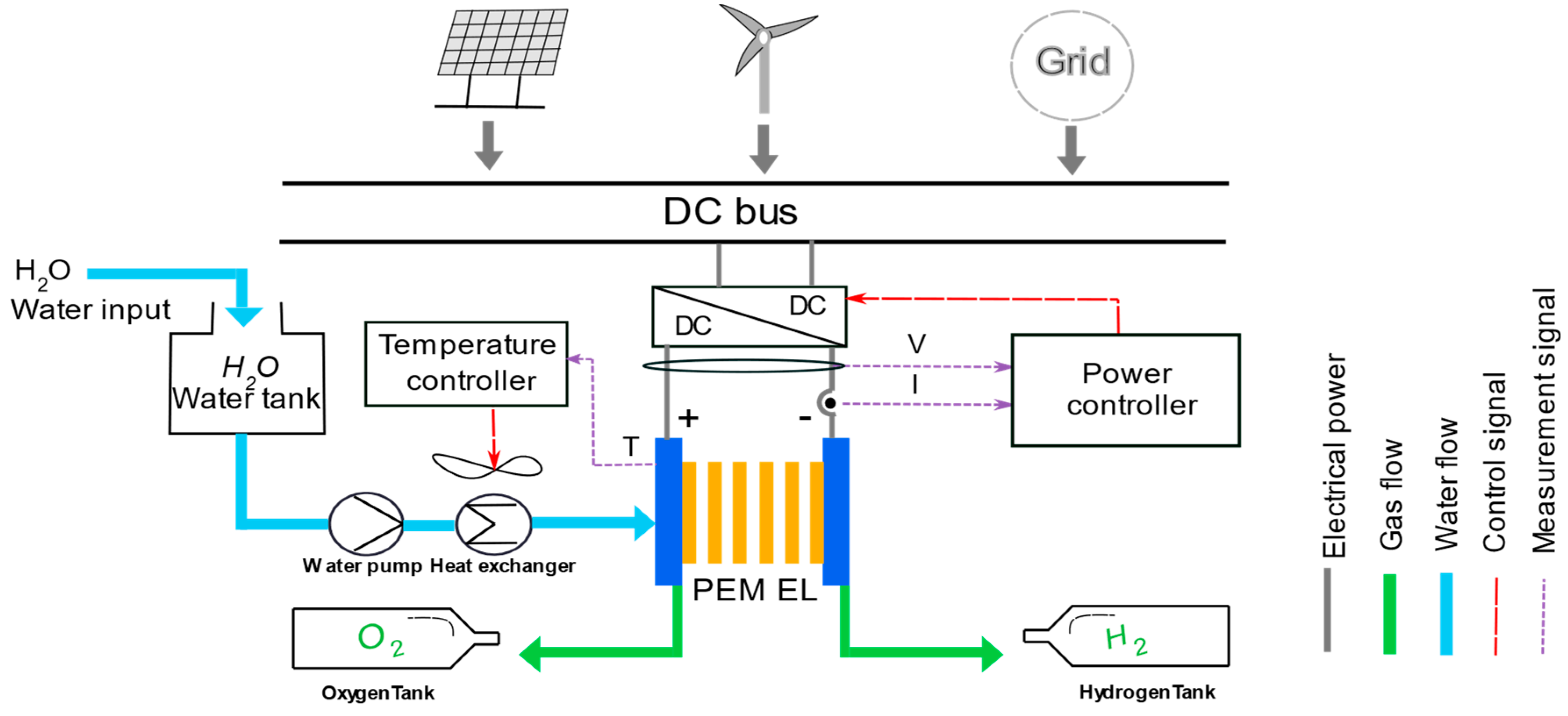
2. Presentation of the Hydrogen Production System Based on PEM EL Technology
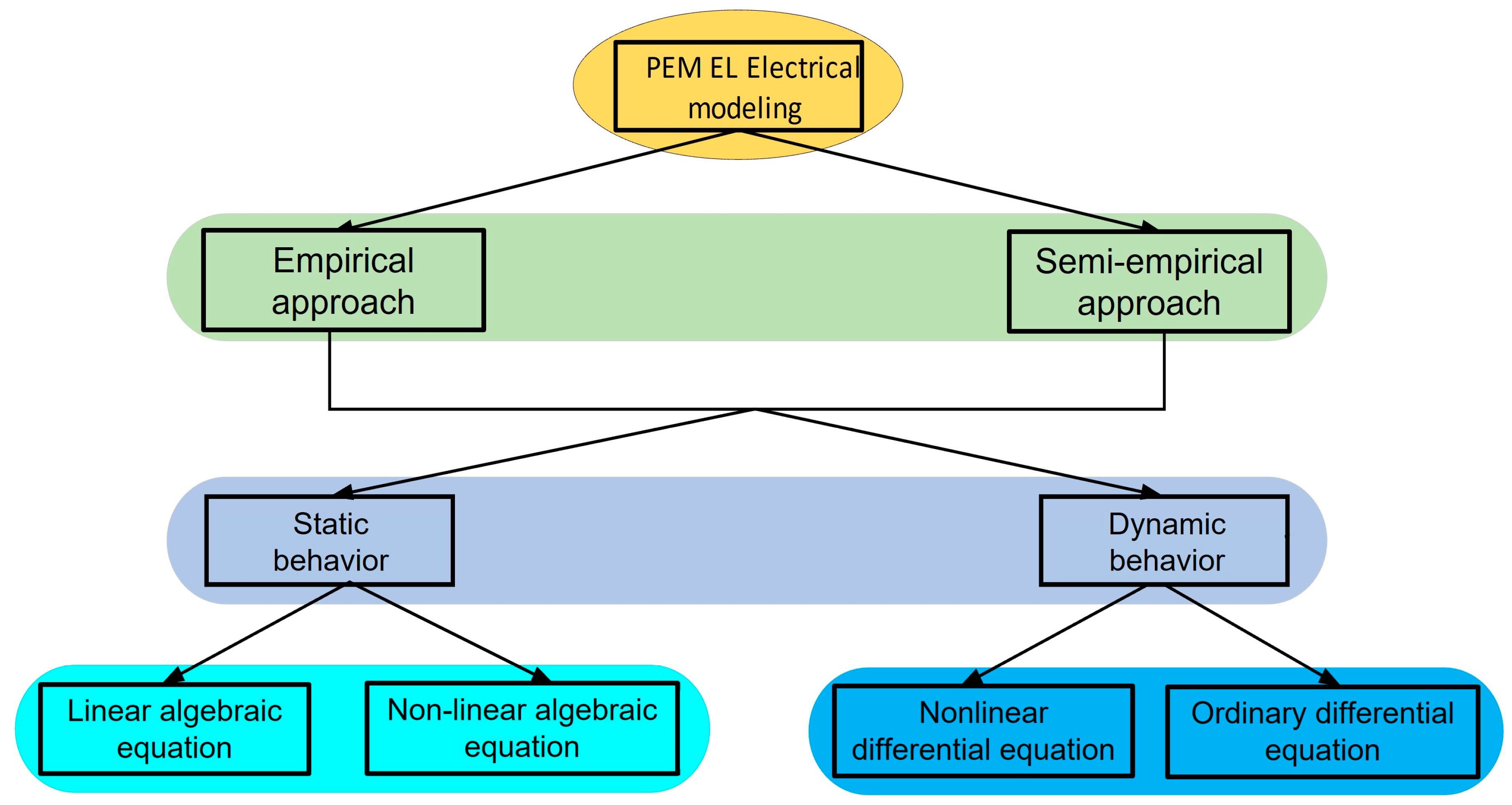
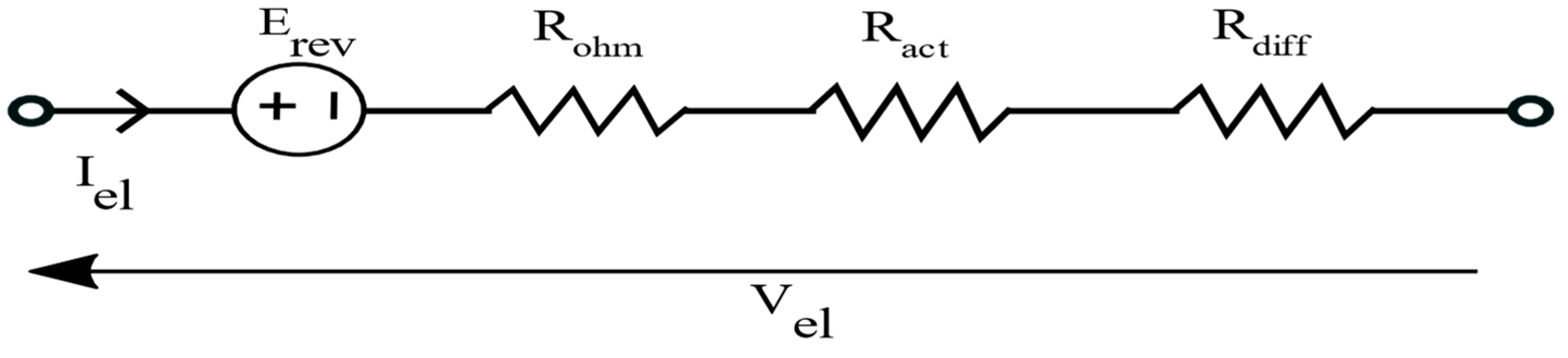
3. Electrical Modeling of PEM
3.1. Empirical Approach
3.1.1. Static Modeling
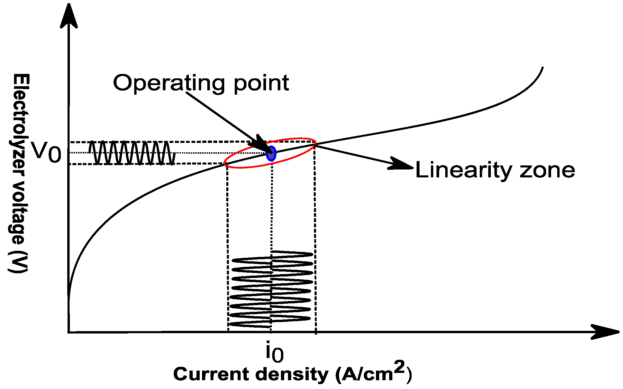
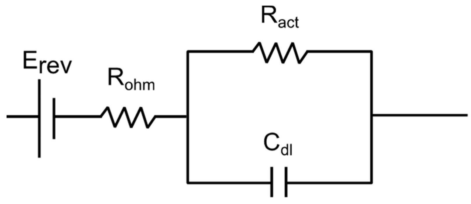
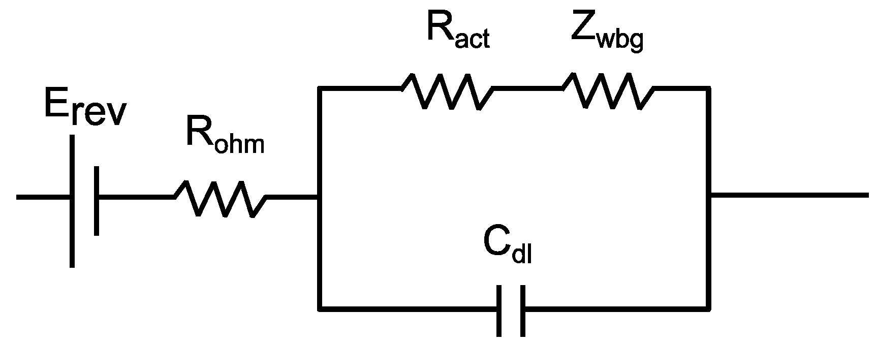
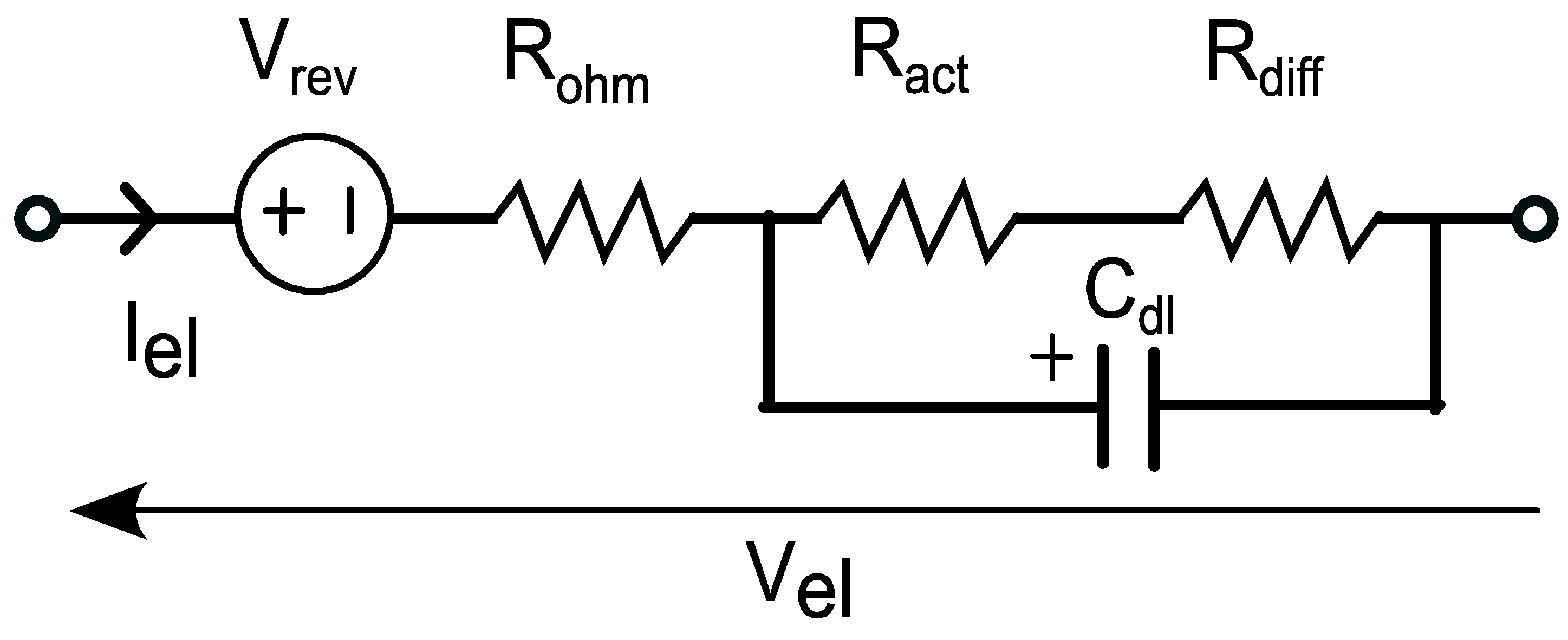
3.1.2. Dynamic Modeling
Electrochemical Impedance Spectroscopy
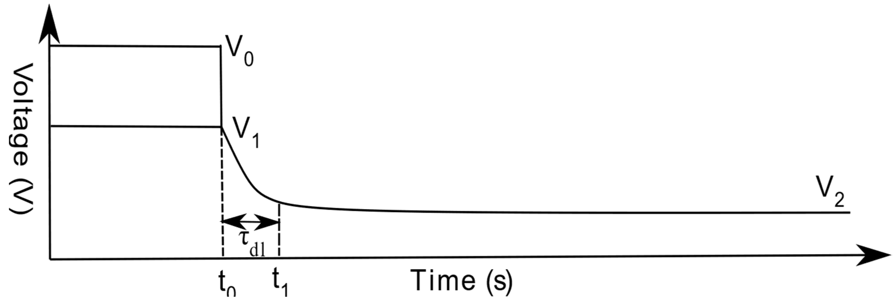
Current Interruption
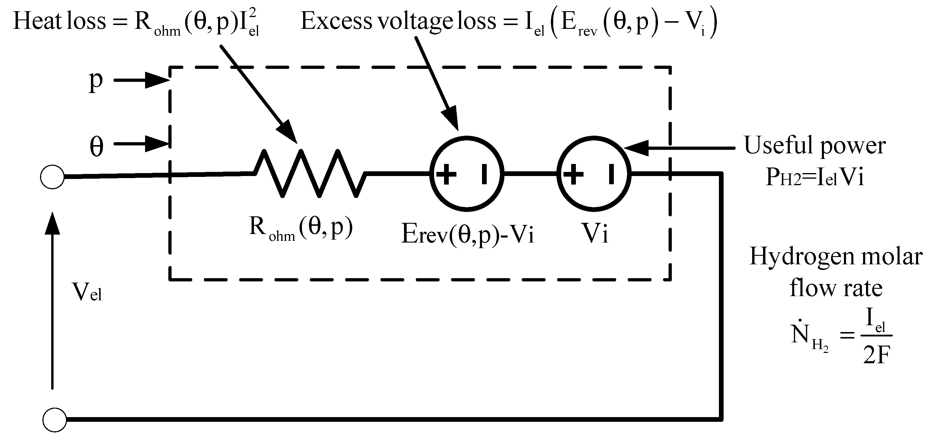
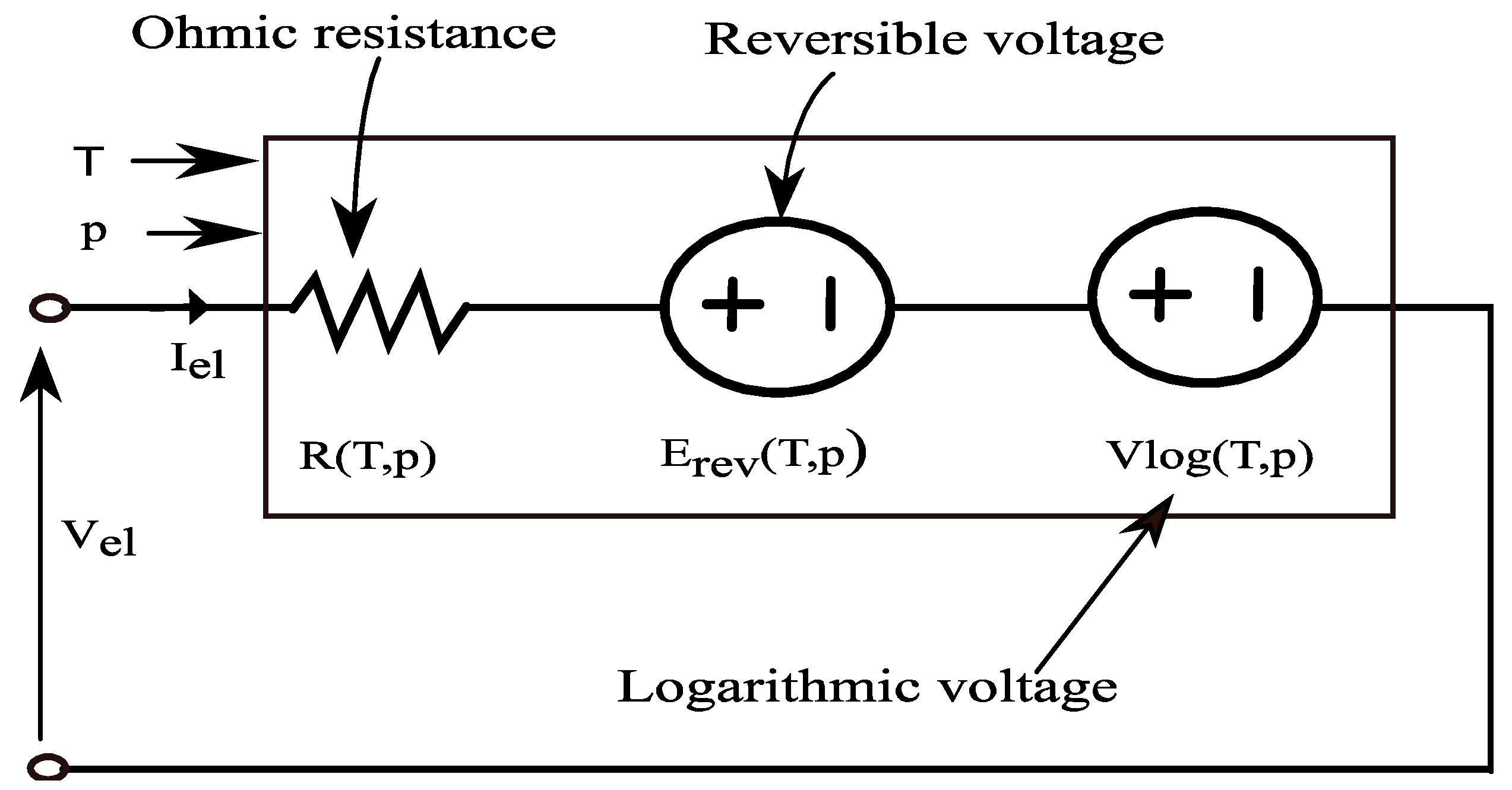
3.2. Semi-Empirical Approach
3.2.1. Static Modeling
Reversible Voltage
Ohmic Losses

| Empirical Method | Ohmic Resistance (Unit) | Reference |
|---|---|---|
| EIS technique | Constant value (Ohm) | [46,49,50,72,84,85] |
| CI technique | Constant value (Ohm) | [51,53,56] |
| Empirical correlation | [81] |
Activation Losses
| Expressions | Activation Overpotential at Cathode | References |
|---|---|---|
| Neglected | [4,31,63,90,91,93,106,107,110] | |
| Considered | [79] | |
| Considered | [32,43,75,76,78,80,81,82,86,87,97,98,101,111,112] | |
| Considered | [6,57,58,62,73,74,80,96,105,113] | |
| Considered | [89,94,109,110] | |
| Neglected | [88] | |
| Neglected | [78] | |
| Neglected | [108] | |
| Neglected | [59,67] | |
| Considered | [60] |
| i0,an (A.cm−2) (Anode Catalyst) | i0,cat (A.cm−2) (Cathode Catalyst) | αan (Per unit) | αcat (Per unit) | Operation Temperature (Kelvin) | Operation Pressure (bar) | References |
|---|---|---|---|---|---|---|
| 10−12–10−9 (Pt) | 10−4–10−3 (Pt) | 0.5 | 0.5 | 353 | –– | [104] |
| 0.76 × 10⁻⁵–4.93 × 10⁻⁵ (Pt) | 0.18–0.39 (Pt) | 0.1–0.6 | 0.5 | 283–333 | 10 | [58] |
| 4.2 × 10⁻³–5 × 10⁻⁴ (Pt) | 0.179–0.433 (Pt) | 0.179–0.433 | 0.5 | 293–333 | 10 | [57] |
| 0.13 × 10⁻³ (—) | X | 0.452 | X | 353 | –– | [4] |
| 10−13–10−6 (Ir-Ru) | 0.025–0.1568 (Pt) | 0.5 | 0.5 | 313–328 | 1–70 | [82] |
| 3.348 × 10⁻⁶ (—) | 4.957 × 10⁻² (—) | 0.42 | 0.5 | 353 | 1 | [74] |
| Cal (Pt) | Cal (Pt) | 0.5 | 0.5 | 300–353 | 1–5 | [95] |
| 0.1548 × 10⁻² (—) | 0.3539 × 10⁻¹ (—) | 0.7178 | 0.6395 | 300–303 | 1 | [105] |
| Cal (—) | X | 0.5 | X | –– | –– | [59] |
| Cal (—) | X | 0.5 | X | –– | –– | [71] |
| 1 × 10⁻¹⁰ (—) | 1 × 10⁻³ (—) | 2 | 0.5 | 328 | 100 | [86] |
| 1 × 10⁻⁶ (Pt) | 0.29 (Pt) | 0.1 | 0.9 | 293 | 1 | [94] |
| 10−9–10−12 (Pt) | 10−3–10−4 (Pt–Ir) | 0.5 | 0.5 | 313–353 | –– | [7] |
| 1.573 × 10⁻⁸–6.667 × 10⁻¹⁰ (With γan = 150) (—) | X | 0.648–0.655 | X | 313–353 | –– | [88] |
| 1 × 10⁻⁷ (Pt) | 1 × 10⁻¹ (Pt) | 0.8 | 0.25 | 283–363 | 10–90 | [81] |
| 1 × 10⁻⁶ (—) | 1 × 10⁻¹ (—) | 2 | 0.5 | 353 | 13.6 | [76] |
| 1 × 10⁻⁹–8 × 10⁻⁷ (Pt) | 3 × 10⁻³ (Pt) | 0.5 | 0.5 | 303–353 | –– | [79] |
| 1 × 10⁻⁷ (—) | 2 × 10⁻³ (—) | 2 | 0.5 | 280–360 | 1–350 | [32] |
| 1.65 × 10⁻⁸ (—) | 0.09 (—) | 0.5 | 0.5 | 297.6–310 | 13.6 | [114] |
| 2.27 × 10⁻⁷–1.53 × 10⁻⁶ (—) | 4.9 × 10⁻²–1.05 × 10⁻¹ (—) | 0.5 | 0.5 | 298–323 | –– | [69] |
| 0.111 (—) | 0.653 (—) | 0.186 | 0.5 | 343 | 20 | [78] |
| Cal (Ir–O2) | Cal (Pt) | –– | –– | 313–353 | 1–30 | [101] |
| 2.472–1.43 (—) | 2754–6024 | 0.8433–0.9484 | 0.8911–0.5491 | 298–333 | 1 | [99] |
| Cal (—) | X | 0.5 | X | 318–353 | 70–155 | [108] |
| 1 × 10⁻¹⁰ (—) | 1 × 10⁻³ (—) | 0.5 | 0.5 | 293–353 | 1–200 | [89] |
| Cal (Pt) | Cal (Pt) | 0.5 | 0.5 | 443 | 1 | [73] |
| Cal (Pt) | Cal (IrO2) | 1.2 | 0.5 | 353 | 1 | [43] |
| Cal (Pt–IrO2) | X | 0.7353 | X | 303–333 | 15–35 | [43] |
| 4.5756 × 10⁻⁷ (—) | X | 0.5316 | X | 353 | 13.44 | [90] |
| Cal (Pt-IrO2) | X | 0.7353 | X | 303–333 | 15–35 | [67] |
| 1 × 10⁻⁶–1 × 10⁻¹ (—) | 0.01–10 (—) | 0.5 | 0.5 | 333–368 | 1–40 | [6] |
| 1 × 10⁻⁷ (Pt-Ir) | 1 × 10⁻³ (Pt) | 0.5 | 0.5 | 293–353 | 1–20 | [109] |
| 1 × 10⁻¹²–1 × 10⁻⁸ (Pt) | 1 × 10⁻³–10 (Pt) | 0.5 | 0.5 | 313–353 | 1–70 | [80] |
| Cal (—) | Cal (—) | 0.5 | 0.5 | 353 | — | [96] |
| 1.381 × 10⁻⁵ (—) | 4.64 × 10⁻³ (—) | 2 | 0.5 | 293 | 1 | [97] |
| 1.65 × 10⁻¹⁸ (—) | 0.09 (—) | — | — | 288 | 7 | [111] |
| Cal (Ir-O2) | Cal (Pt) | 0.5 | 0.5 | 353 | — | [61] |
Diffusion Overpotential/Mass Transport Overpotential/Concentration Overpotential
| At the Anode (i0,an) | At the Cathode (i0,cat) | References |
|---|---|---|
| Not considered | [108] | |
| [43,101] | ||
| [59,61,71,73,95,96,110] |
| Anodic Catalyst | Cathodic Catalyst | References | ||||||
|---|---|---|---|---|---|---|---|---|
| Pt | 1 × 10⁻¹¹ | 76 | N.C | Pt | 1 × 10⁻³ | 18 | N.C | [95,115] |
| — | 2 × 10⁻¹² | 52.649 | N.C | — | X | X | N.C | [110] |
| IrO2 | 5.35 × 10⁻⁷ | 15 | 100 | Pt | 1 × 10⁻³ | 18 | 40 | [101] |
| Pt | 8.4 × 10⁻¹¹ | 76 | N.C | Pt | 3224 | 18 | N.C | [73] |
| (Pt − IrO2) | 1.08 × 10⁻¹⁸ | 52.994 | N.C | X | X | X | X | [59,67] |
| — | 1.7 × 101 | 76 | N.C | — | 4.6 × 10⁻¹ | 18 | N.C | [96] |
| IrO2 | — | 62.836 | N.C | Pt | — | 24.359 | N.C | [61] |
3.2.2. Dynamic Modeling
4. PEM EL Sub-Models
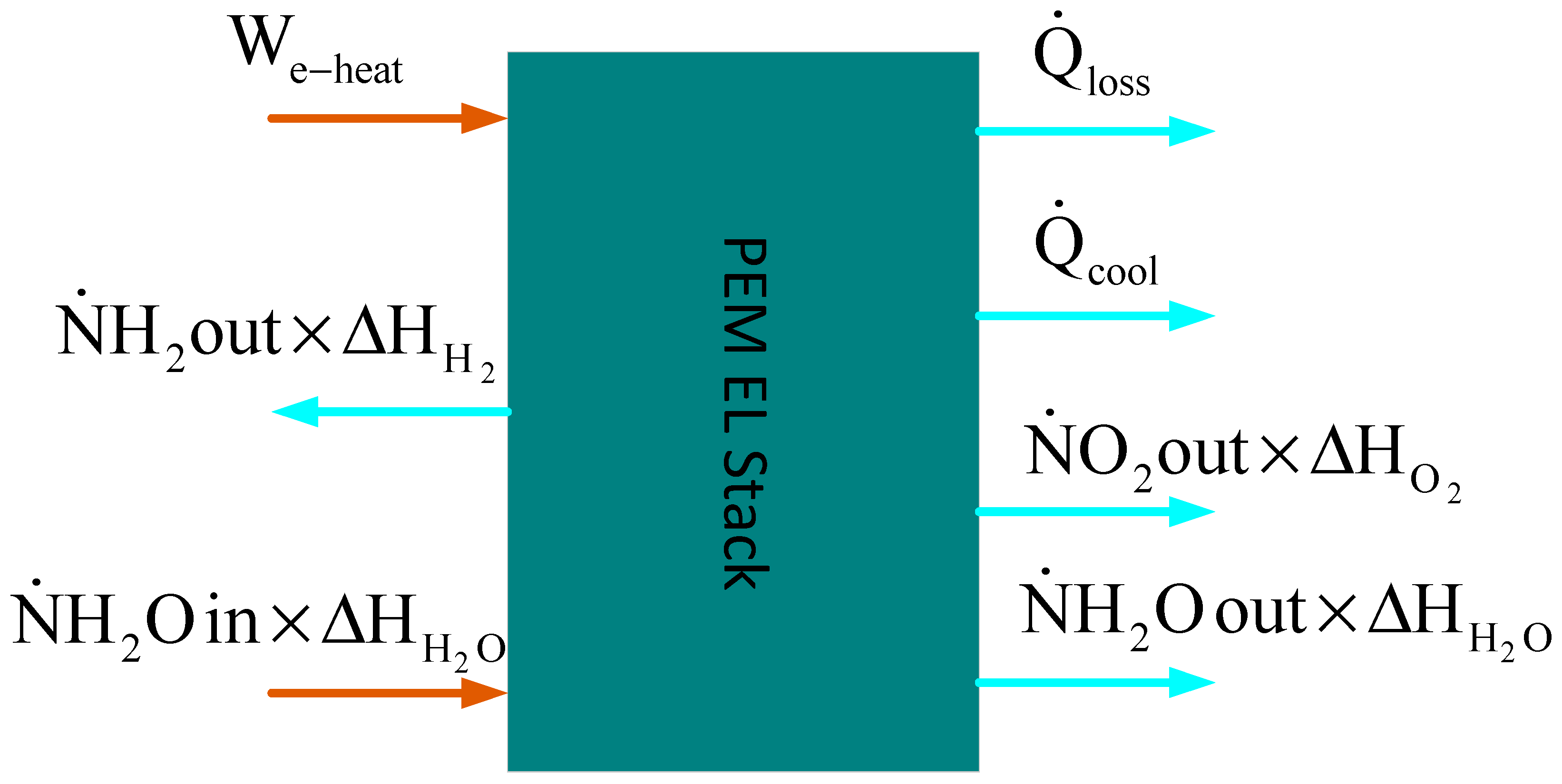
4.1. Thermal Sub-Model
| Expression | Cooling System | Parameters | References |
|---|---|---|---|
Are neglected | Not included | Cth and h are identified using the nonlinear least squares method | [4,62,99] |
| Included | Cth and Rth estimated experimentally | [110] | |
| Included | Not mentioned | [107,111,127] | |
| Included | Cth and Rth are identified using particle swarm optimization (PSO) | [59,67] |
4.2. PEM EL Efficiency
4.2.1. Faraday Efficiency
4.2.2. Voltage efficiency
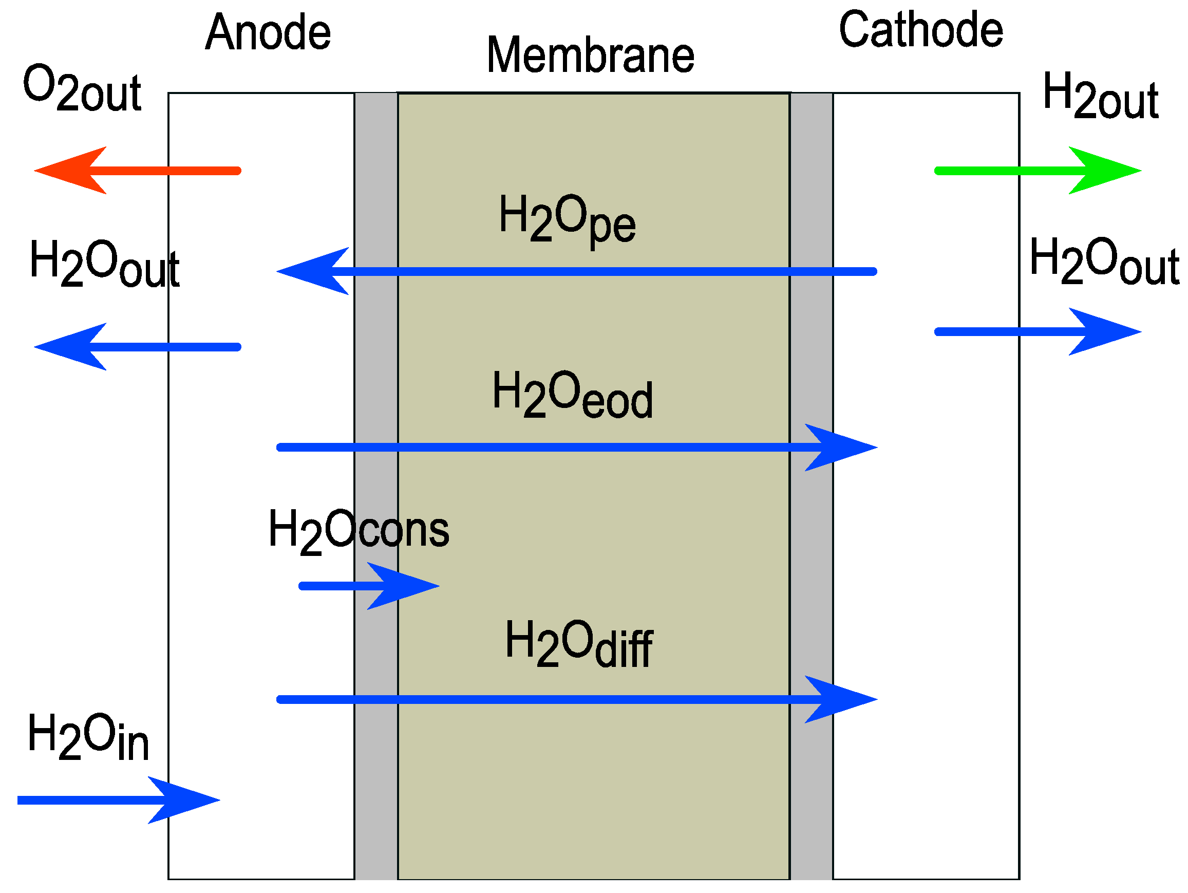
4.3. Mass Flow of Gas Products and Water Consumed
4.4. Hydrogen Storage Tank Sub-Model
5. DC/DC Power Converter for PEM EL
6. Control Strategy of DC-DC Converter–PEM EL Systems
- -
- Regulation of the hydrogen flow rate to its constant reference through the PEM EL current under a wide variation of operating conditions. The reference current can be determined as follows:
| Hydrogen Production Configuration | Modeling Methods of PEM EL | DC/DC Converter Used to Supply PEM EL | Magnitude Controlled | Control Law Strategy | References |
|---|---|---|---|---|---|
| PV-PEM EL | EIS (dynamic model) | Buck converter | Current regulator | Linear control (NM) | [49] |
| PEM EL-PEM FC | Model-based on experimental data (linear time invariance state space in discrete-time) | Buck converter | Voltage regulator | MPC with a disturbance’s observer | [153] |
| PEM EL-Three-phase grid | Static linear model (Rstack-Vstack) | Phase-shifted full-bridge | Current regulator | PI control | [154] |
| PEM EL-DC bus | Dynamic linear model | IBC converter | Voltage regulator | SMC control with linear observer | [155] |
| PEM EL-DC bus | Dynamic linear model | IBC converter | Voltage regulator | SMC control | [156] |
| PEM EL-DC bus | Dynamic linear model | Quadratic buck converter | Current regulator | SMC control | [20] |
| PEM EL-DC bus | Static nonlinear model | Synchronous buck converter | Voltage regulator | PI control | [143] |
| PEM EL Three-phase grid | Static linear model | Phase-shift full-bridge converter | Current regulator | PI control | [157] |
| Micro wind generator-PEM EL | Static linear model | Full bridge converter | Current regulator | PI control | [158] |
| DC-bus PEM EL | Linear static model | Three-levelinterleaved DC-DC buck converter | Voltage control | PI control | [19] |
| High DC voltage RES sources | Dynamic linear model | Stacked interleaved buck converter | Voltage control | PI control | [119] |
| PV-PEM EL | Linear static model | Classical buck converter | Voltage control | PID control | [36] |
| PV-PEM EL | Nonlinear static model | Classical buck converter | Voltage control | PI control | [159] |
| DC-bus PEM EL | Linear static model | Stacked interleaved DC-DC buck converter | Combined with voltage control and current control | PID control | [21] |
| DC-bus PEM EL | Linear static model | Buck converter | Current control | ST- SMC control | [160] |
- -
- Control hydrogen flow rate through PEM EL current as shown above according to the state of charge of the hydrogen tank and hydrogen consumption by fuel cells.
- -
- Regulate the PEM EL voltage to its reference voltage despite the DC bus voltage variation and the operation point variation.
- -
- Some objectives can be added, such as ensuring equal current sharing between the three parallel legs when the IBC is used, etc.
| Model Adopted | Identification Method | Parameter’s Vector | Mean Relative Error | References |
|---|---|---|---|---|
| Nonlinear static model | Nonlinear least square identification (NLS) | 0.32% | [4] | |
| Model-based on CI method | Current interruption (CI) | 7.38% | [53,56] | |
| Nonlinear static model | MATLAB identification tools | 0.11% | [62,99] | |
| Nonlinear static model | Particle swarm optimization algorithm (PSO) | 2% | [59] | |
| Linear dynamic model | Linear dynamic last square regression | 15% for static model;4% for dynamic model | [15,20,125] | |
| Linear dynamic model | EIS method | Not mentioned | [49] |
7. Discussion
8. Conclusions
Author Contributions
Funding
Conflicts of Interest
Nomenclature
| List of symbols and abbreviations | |
| ARLS | Adaptative least square regression |
| CI | Current interruption |
| CTC | Charge transfer coefficient |
| DC/DC | Direct current/direct current |
| ECD | Exchange current density |
| EEC | Equivalent electrical circuit |
| EIS | Electrochemical impedance spectroscopy |
| EKF | Extended Kalman filter |
| GDL | Gas diffusion layer |
| IBC | Interleaved buck converter |
| IHBC | Isolated Half-Bridge Converter |
| KF | Kalman filter |
| LSR | Least square regression |
| MPC | Model predictive control |
| MPPT | Maximum power point tracker |
| NVR | Nature voltage response method |
| PEM EL | Proton exchange membrane electrolyzer |
| PI | Proportional integral |
| PID | Proportional-integral-derivative |
| PRBS | Pseudo-random binary sequence excitation |
| PSO | Particle swarm optimization |
| Dw H+ | Concentration of protons participating in en masse diffusion |
| e | Parameterized pre-exponential factor of i0,an |
| Eact | Activation energy required for the electron transport in the electrodes |
| Epro | Activation energy required for the proton transport in the membrane |
| F | Faraday’s constant |
| f | Parameterized coefficient of i0,an |
| H2 | Hydrogen |
| H2O | Water |
| H2Ocon | Water consumed by electrolysis process |
| Iel | Electrolyzer current |
| i | Current density |
| i0 | Electrode exchange current density |
| iLim | Diffusion limit current density |
| iv | Current density of illumination |
| k | Constant parameter fitting |
| Mass flow | |
| N | Molar quantity of O2/H2/H2O |
| Molar flow rate of O2/H2/H2O | |
| Ncell | Number of cells |
| O2 | Oxygen |
| p | Pressure |
| P | Absorbed electrical power by PEM EL |
| PH2 | Useful power of PEM EL |
| pi | Partial pressure of the component i |
| psatH2O | Saturated water pressure |
| Q | Volumetric flow rate |
| Heat flow rate | |
| R | Universal gas constant |
| R(p,θ) | Equivalent resistance as a function of pressure Pa and temperature in C0 |
| R(p,T) | Equivalent resistance as a function of pressure in Pa and temperature in K |
| Rth | Thermal resistance |
| s1, s2, s3, r1, r2, t1, t2 and t3 | Fitting parameters of Ullberg model |
| T | Temperature in Kelvin |
| Tm | Cooling medium temperature |
| v | Volume |
| V | Voltage |
| VHHV | High heating value voltage of hydrogen |
| Vi | Ideal voltage of PEM electrolyzer |
| Vj | Drop voltage of j with j= ohm/act/diff |
| Vlog | Logarithm voltage |
| Vth | Thermoneutral voltage |
| We-heat | Represents the electrical power dissipation as heat |
| z | Compressibility factor |
| Zwbg | Warburg diffusion element |
| act | Activation |
| amb | Ambient |
| an/cat | Anode/cathode |
| cell | Cell |
| PV | Photovoltaic |
| RES | Renewable energy sources |
| SI | System identification |
| slpm | Standard liter per minute |
| SMC | Sliding mode control |
| WT | Wind turbine |
| A | Active surface area |
| a, b | Van der Waals coefficients |
| a1, a2, a3, a4 and a5 | Beattie–Bridgeman coefficients |
| aR/P | Activity of reaction/product or water |
| B, C and D | Antoine coefficients |
| Cdl | Double-layer capacitance |
| CH+ | Proton concentration |
| Cp H2/O2 | Molar specific heat of H2/O2 |
| Cth | Lumped thermal capacity |
| Cx | Molar concentration of x species |
| CΣH+ | Concentration of protons participating in surface diffusion |
| dRϴ | Ohmic resistance coefficient of temperature |
| DH+Σ | Diffusion coefficient of protons for the surface diffusion mechanism |
| DGH+ | Diffusion coefficient of protons for the Grotthuss diffusion mechanism |
| cool | Cooling |
| diff | Diffusion |
| EL/el | Electrolyzer |
| ele | Electronic |
| env | Environment |
| eod | Electro-osmotic drag |
| gen | Generated |
| in | Input |
| init | Initial |
| loss | Losses |
| mem | Membrane |
| ohm | Ohmic |
| out | Output |
| pe | Pressure gradient |
| pump | Of the pump |
| ref | Reference condition |
| rev | Reversible voltage |
| stack | Of the stack |
| theo | Theoretical |
| ΔS0 | Entropy changes |
| ΔG0 | Gibbs’ free energy change |
| ΔH0 | Enthalpy change |
| Δp | Differential pressure |
| ΦperH2/O2 | Flux density across the membrane of H2/O2 |
| Φ | Parameter vectors |
| α | Charge transfer coefficient |
| δc | Stefan–Maxwell diffusion ratio |
| ε | Porosity of the membrane |
| μ | Concentration overpotential |
| ς | Tortuosity factor |
| τdl | Time constant |
| θ | Temperature in degrees Celsius |
| δ | Membrane tackiness |
| σ | Membrane conductivity |
| ρel | Electronic conductor resistivity |
| λ | Membrane water content |
| κ | Experimental tuned coefficient |
| ℓel | Length of electronic conductors |
| ηel | Electrolyzer efficiency |
| γ | Roughness factor |
| ηF | Faraday efficiency |
| ηV | Voltage efficiency |
| ηcell | Cell efficiency |
| β | Experimentally defined coefficient |
References
- Manzanedo, R.D.; Manning, P. COVID-19: Lessons for the climate change emergency. Sci. Total Environ. 2020, 742, 140563. [Google Scholar] [CrossRef]
- Jin, S. COVID-19, Climate Change, and Renewable Energy Research: We Are All in This Together, and the Time to Act Is Now. ACS Energy Lett. 2020, 5, 1709–1711. [Google Scholar] [CrossRef]
- Ngamroo, I. Robust coordinated control of electrolyzer and PSS for stabilization of microgrid based on PID-based mixed H2/H∞ control. Renew. Energy 2012, 45, 16–23. [Google Scholar] [CrossRef]
- Lebbal, M.E.; Lecœuche, S. Identification and monitoring of a PEM electrolyser based on dynamical modelling. Int. J. Hydrog. Energy 2009, 34, 5992–5999. [Google Scholar] [CrossRef]
- Rashid, M.M.; Mesfer, M.K.A.; Naseem, H.; Danish, M. Hydrogen Production by Water Electrolysis: A Review of Alkaline Water Electrolysis, PEM Water Electrolysis and High Temperature Water Electrolysis. Int. J. Eng. Adv. Technol. 2015, 4, 80–93. [Google Scholar]
- Toghyani, S.; Fakhradini, S.; Afshari, E.; Baniasadi, E.; Abdollahzadeh Jamalabadi, M.Y.; Safdari Shadloo, M. Optimization of operating parameters of a polymer exchange membrane electrolyzer. Int. J. Hydrog. Energy 2019, 44, 6403–6414. [Google Scholar] [CrossRef]
- Tijani, A.S.; Yusup, N.A.B.; Rahim, A.H.A. Mathematical Modelling and Simulation Analysis of Advanced Alkaline Electrolyzer System for Hydrogen Production. Procedia Technol. 2014, 15, 798–806. [Google Scholar] [CrossRef]
- Toshihiko, Y.; Koichi, K. Toyota MIRAI Fuel Cell Vehicle and Progress Toward a Future Hydrogen Society. Electrochem. Soc. Interface 2015, 24, 45. [Google Scholar]
- Grigoriev, S.A.; Kalinnikov, A.A. Mathematical modeling and experimental study of the performance of PEM water electrolysis cell with different loadings of platinum metals in electrocatalytic layers. Int. J. Hydrog. Energy 2017, 42, 1590–1597. [Google Scholar] [CrossRef]
- Pham, C.V.; Escalera-López, D.; Mayrhofer, K.; Cherevko, S.; Thiele, S. Essentials of High Performance Water Electrolyzers—From Catalyst Layer Materials to Electrode Engineering. Adv. Energy Mater. 2021, 11, 2101998. [Google Scholar] [CrossRef]
- Zhang, K.; Liang, X.; Wang, L.; Sun, K.; Wang, Y.; Xie, Z.; Wu, Q.; Bai, X.; Hamdy, M.S.; Chen, H.; et al. Status and perspectives of key materials for PEM electrolyzer. Nano Res. Energy 2022, 1, e9120032. [Google Scholar] [CrossRef]
- Jiang, G.; Yu, H.; Li, Y.; Yao, D.; Chi, J.; Sun, S.; Shao, Z. Low-Loading and Highly Stable Membrane Electrode Based on an Ir@WO(x)NR Ordered Array for PEM Water Electrolysis. ACS Appl. Mater. Interfaces 2021, 13, 15073–15082. [Google Scholar] [CrossRef] [PubMed]
- Onda, K.; Murakami, T.; Hikosaka, T.; Kobayashi, M.; Notu, R.; Ito, K. Performance Analysis of Polymer-Electrolyte Water Electrolysis Cell at a Small-Unit Test Cell and Performance Prediction of Large Stacked Cell. J. Electrochem. Soc. 2002, 149, A1069. [Google Scholar] [CrossRef]
- Hernández-Gómez, Á.; Ramirez, V.; Guilbert, D.; Saldivar, B. Development of an adaptive static-dynamic electrical model based on input electrical energy for PEM water electrolysis. Int. J. Hydrog. Energy 2020, 45, 18817–18830. [Google Scholar] [CrossRef]
- Guilbert, D.; Vitale, G. Dynamic Emulation of a PEM Electrolyzer by Time Constant Based Exponential Model. Energies 2019, 12, 750. [Google Scholar] [CrossRef]
- Guida, V.; Guilbert, D.; Douine, B. Candidate Interleaved DC-DC Buck Converters for Electrolyzers: State-of-the-Art and Perspectives. In Proceedings of the 2018 IEEE International Conference on Environment and Electrical Engineering and 2018 IEEE Industrial and Commercial Power Systems Europe, EEEIC/I and CPS Europe 2018, Palermo, Italy, 12–15 June 2018. [Google Scholar]
- Guida, V.; Guilbert, D.; Douine, B. Literature Survey of Interleaved DC-DC StepDown Converters for Proton Exchange Membrane Electrolyzer Applications. Trans. Environ. Electr. Eng. 2019, 3, 33–43. [Google Scholar] [CrossRef]
- Yodwong, B.; Guilbert, D.; Phattanasak, M.; Kaewmanee, W.; Hinaje, M.; Vitale, G. AC-DC Converters for Electrolyzer Applications: State of the Art and Future Challenges. Electronics 2020, 9, 912. [Google Scholar] [CrossRef]
- Yodwong, B.; Guilbert, D.; Kaewmanee, W.; Phattanasak, M. Energy Efficiency Based Control Strategy of a Three-Level Interleaved DC-DC Buck Converter Supplying a Proton Exchange Membrane Electrolyzer. Electronics 2019, 8, 933. [Google Scholar] [CrossRef]
- Guilbert, D.; Yodwong, B.; Kaewmanee, W.; Phattanasak, M.; Hinaje, M. Hydrogen Flow Rate Control of a Proton Exchange Membrane Electrolyzer. In Proceedings of the 2019 Research, Invention, and Innovation Congress (RI2C), Bangkok, Thailand, 11–13 December 2019. [Google Scholar]
- Maamouri, R.; Guilbert, D.; Zasadzinski, M.; Rafaralahy, H. Proton exchange membrane water electrolysis: Modeling for hydrogen flow rate control. Int. J. Hydrog. Energy 2021, 46, 7676–7700. [Google Scholar] [CrossRef]
- Serna, Á.; Yahyaoui, I.; Normey-Rico, J.E.; de Prada, C.; Tadeo, F. Predictive control for hydrogen production by electrolysis in an offshore platform using renewable energies. Int. J. Hydrog. Energy 2017, 42, 12865–12876. [Google Scholar] [CrossRef]
- Rahim, A.A.; Tijani, A.S.; Kamarudin, S.; Hanapi, S. An overview of polymer electrolyte membrane electrolyzer for hydrogen production: Modeling and mass transport. J. Power Sources 2016, 309, 56–65. [Google Scholar] [CrossRef]
- Olivier, P.; Bourasseau, C.; Bouamama, P.B. Low-temperature electrolysis system modelling: A review. Renew. Sustain. Energy Rev. 2017, 78, 280–300. [Google Scholar] [CrossRef]
- Hernández-Gómez, Á.; Ramirez, V.; Guilbert, D. Investigation of PEM electrolyzer modeling: Electrical domain, efficiency, and specific energy consumption. Int. J. Hydrog. Energy 2020, 45, 14625–14639. [Google Scholar] [CrossRef]
- Falcão, D.; Pinto, A. A review on PEM electrolyzer modelling: Guidelines for beginners. J. Clean. Prod. 2020, 261, 121184. [Google Scholar] [CrossRef]
- Guilbert, D.; Collura, S.M.; Scipioni, A. DC/DC converter topologies for electrolyzers: State-of-the-art and remaining key issues. Int. J. Hydrog. Energy 2017, 42, 23966–23985. [Google Scholar] [CrossRef]
- Yodwong, B.; Guilbert, D.; Phattanasak, M.; Kaewmanee, W.; Hinaje, M.; Vitale, G. Proton Exchange Membrane Electrolyzer Modeling for Power Electronics Control: A Short Review. C—J. Carbon Res. 2020, 6, 29. [Google Scholar] [CrossRef]
- Folgado, F.J.; González, I.; Calderón, A.J. Simulation platform for the assessment of PEM electrolyzer models oriented to implement digital Replicas. Energy Convers. Manag. 2022, 267, 115917. [Google Scholar] [CrossRef]
- Beainy, A.; Karami, N.; Moubayed, N. Simulink model for a PEM electrolyzer based on an equivalent electrical circuit. In Proceedings of the International Conference on Renewable Energies for Developing Countries 2014, Beirut, Lebanon, 26–27 November 2014. [Google Scholar]
- Gorgun, H. Dynamic modelling of a proton exchange membrane (PEM) electrolyzer. Int. J. Hydrog. Energy 2006, 31, 29–38. [Google Scholar] [CrossRef]
- Yigit, T.; Selamet, O.F. Mathematical modeling and dynamic Simulink simulation of high-pressure PEM electrolyzer system. Int. J. Hydrog. Energy 2016, 41, 13901–13914. [Google Scholar] [CrossRef]
- Atlam, O. An experimental and modelling study of a photovoltaic/proton-exchange membrane electrolyser system. Int. J. Hydrog. Energy 2009, 34, 6589–6595. [Google Scholar] [CrossRef]
- Atlam, O.; Kolhe, M. Equivalent electrical model for a proton exchange membrane (PEM) electrolyser. Energy Convers. Manag. 2011, 52, 2952–2957. [Google Scholar] [CrossRef]
- Beainy, A.; Moubayed, N. Influence of variations of operating parameters on the functioning of a PEM electrolyzer and PEM fuel cell systems. In Proceedings of the 2016 Third International Conference on Electrical, Electronics, Computer Engineering and their Applications (EECEA), Beirut, Lebanon, 21–23 April 2016. [Google Scholar]
- Albarghot, M.; Rolland, L. MATLAB/Simulink modelling and experimental results of a PEM electrolyzer powered by a solar panel. In Proceedings of the 2016 IEEE Electrical Power and Energy Conference (EPEC), Ottawa, ON, Canada, 12–14 October 2016. [Google Scholar]
- Ulleberg, Ø. Modeling of advanced alkaline electrolyzers: A system simulation approach. Int. J. Hydrog. Energy 2003, 28, 21–33. [Google Scholar] [CrossRef]
- Ulleberg, M. TRNSYS Simulation Models for Solar-Hydrogen Systems. Sol. Energy 1997, 59, 271–279. [Google Scholar] [CrossRef]
- Zhou, T.; Francois, B. Modeling and control design of hydrogen production process for an active hydrogen/wind hybrid power system. Int. J. Hydrog. Energy 2009, 34, 21–30. [Google Scholar] [CrossRef]
- Dieguez, P.; Ursua, A.; Sanchis, P.; Sopena, C.; Guelbenzu, E.; Gandia, L. Thermal performance of a commercial alkaline water electrolyzer: Experimental study and mathematical modeling. Int. J. Hydrog. Energy 2008, 33, 7338–7354. [Google Scholar] [CrossRef]
- Deshmukh, S.S.; Boehm, R.F. Review of modeling details related to renewably powered hydrogen systems. Renew. Sustain. Energy Rev. 2008, 12, 2301–2330. [Google Scholar] [CrossRef]
- Ziogou, C.; Ipsakis, D.; Seferlis, P.; Bezergianni, S.; Papadopoulou, S.; Voutetakis, S. Optimal production of renewable hydrogen based on an efficient energy management strategy. Energy 2013, 55, 58–67. [Google Scholar] [CrossRef]
- Liso, V.; Savoia, G.; Araya, S.S.; Cinti, G.; Kær, S.K. Modelling and Experimental Analysis of a Polymer Electrolyte Membrane Water Electrolysis Cell at Different Operating Temperatures. Energies 2018, 11, 3273. [Google Scholar] [CrossRef]
- Rakousky, C.; Reimer, U.; Wippermann, K.; Carmo, M.; Lueke, W.; Stolten, D. An analysis of degradation phenomena in polymer electrolyte membrane water electrolysis. J. Power Sources 2016, 326, 120–128. [Google Scholar] [CrossRef]
- Rakousky, C.; Reimer, U.; Wippermann, K.; Kuhri, S.; Carmo, M.; Lueke, W.; Stolten, D. Polymer electrolyte membrane water electrolysis: Restraining degradation in the presence of fluctuating power. J. Power Sources 2017, 342, 38–47. [Google Scholar] [CrossRef]
- Siracusano, S.; Trocino, S.; Briguglio, N.; Baglio, V.; Arico, A.S. Electrochemical Impedance Spectroscopy as a Diagnostic Tool in Polymer Electrolyte Membrane Electrolysis. Materials 2018, 11, 1368. [Google Scholar] [CrossRef]
- Li, N.; Araya, S.S.; Kær, S.K. Long-term contamination effect of iron ions on cell performance degradation of proton exchange membrane water electrolyser. J. Power Sources 2019, 434, 226755. [Google Scholar] [CrossRef]
- Wang, H.; Gaillard, A.; Hissel, D. Online electrochemical impedance spectroscopy detection integrated with step-up converter for fuel cell electric vehicle. Int. J. Hydrog. Energy 2019, 44, 1110–1121. [Google Scholar] [CrossRef]
- Ganeshan, I.S.; Manikandan, V.V.S.; Ram Sundhar, V.; Sajiv, R.; Shanthi, C.; Kottayil, S.K.; Ramachandran, T. Regulated hydrogen production using solar powered electrolyser. Int. J. Hydrog. Energy 2016, 41, 10322–10326. [Google Scholar] [CrossRef]
- van der Merwe, J.; Uren, K.; van Schoor, G.; Bessarabov, D. Characterisation tools development for PEM electrolysers. Int. J. Hydrog. Energy 2014, 39, 14212–14221. [Google Scholar] [CrossRef]
- Martinson, C.A.; Schoor, G.V.; Uren, K.; Bessarabov, D.; Merwe, J.H.P.V.D. Characterisation of a Proton Exchange Membrane Electrolyser Using Electrochemical Impedance Spectroscopy. Ph.D. Thesis, North-West University, Potchefstroom, South Africa, 2012. [Google Scholar]
- Rezaei Niya, S.M.; Hoorfar, M. Study of proton exchange membrane fuel cells using electrochemical impedance spectroscopy technique—A review. J. Power Sources 2013, 240, 281–293. [Google Scholar] [CrossRef]
- Martinson, C.; Van Schoor, G.; Uren, K.; Bessarabov, D. Equivalent electrical circuit modelling of a Proton Exchange Membrane electrolyser based on current interruption. In Proceedings of the 2013 IEEE International Conference on Industrial Technology (ICIT), Cape Town, South Africa, 25–28 February 2013. [Google Scholar]
- Zhang, L.; Zhou, Z.; Chen, Q.; Long, R.; Quan, S. Model Predictive Control for Electrochemical Impedance Spectroscopy Measurement of Fuel Cells Based on Neural Network Optimization. IEEE Trans. Transp. Electrif. 2019, 5, 524–534. [Google Scholar] [CrossRef]
- Hong, P.; Li, J.; Xu, L.; Ouyang, M.; Fang, C. Modeling and simulation of parallel DC/DC converters for online AC impedance estimation of PEM fuel cell stack. Int. J. Hydrog. Energy 2016, 41, 3004–3014. [Google Scholar] [CrossRef]
- Martinson, C.A.; van Schoor, G.; Uren, K.R.; Bessarabov, D. Characterisation of a PEM electrolyser using the current interrupt method. Int. J. Hydrog. Energy 2014, 39, 20865–20878. [Google Scholar] [CrossRef]
- Biaku, C.; Dale, N.; Mann, M.; Salehfar, H.; Peters, A.; Han, T. A semiempirical study of the temperature dependence of the anode charge transfer coefficient of a 6kW PEM electrolyzer. Int. J. Hydrog. Energy 2008, 33, 4247–4254. [Google Scholar] [CrossRef]
- Dale, N.V.; Mann, M.D.; Salehfar, H. Semiempirical model based on thermodynamic principles for determining 6kW proton exchange membrane electrolyzer stack characteristics. J. Power Sources 2008, 185, 1348–1353. [Google Scholar] [CrossRef]
- Espinosa-López, M.; Darras, C.; Poggi, P.; Glises, R.; Baucour, P.; Rakotondrainibe, A.; Besse, S.; Serre-Combe, P. Modelling and experimental validation of a 46 kW PEM high pressure water electrolyzer. Renew. Energy 2018, 119, 160–173. [Google Scholar] [CrossRef]
- Ma, Z.; Witteman, L.; Wrubel, J.A.; Bender, G. A comprehensive modeling method for proton exchange membrane electrolyzer development. Int. J. Hydrog. Energy 2021, 46, 17627–17643. [Google Scholar] [CrossRef]
- Zhang, Z.; Xing, X. Simulation and experiment of heat and mass transfer in a proton exchange membrane electrolysis cell. Int. J. Hydrog. Energy 2020, 45, 20184–20193. [Google Scholar] [CrossRef]
- Aouali, F.Z.; Becherif, M.; Tabanjat, A.; Emziane, M.; Mohammedi, K.; Krehi, S.; Khellaf, A. Modelling and Experimental Analysis of a PEM Electrolyser Powered by a Solar Photovoltaic Panel. Energy Procedia 2014, 62, 714–722. [Google Scholar] [CrossRef]
- Ayivor, P.; Torres, J.; Van Der Meijden, M.A.M.M.; Van Der Pluijm, R.; Stouwie, B. Modelling of Large Size Electrolyzer for Electrical Grid Stability Studies in Real Time Digital Simulation. In Proceedings of the 3rd International Hybrid Power Systems Workshop, Tenerife, Spain, 8–9 May 2018. [Google Scholar]
- Selamet, Ö.F.; Becerikli, F.; Mat, M.D.; Kaplan, Y. Development and testing of a highly efficient proton exchange membrane (PEM) electrolyzer stack. Int. J. Hydrog. Energy 2011, 36, 11480–11487. [Google Scholar] [CrossRef]
- Ursua, A.; Gandia, L.M.; Sanchis, P. Hydrogen Production From Water Electrolysis: Current Status and Future Trends. Proc. IEEE 2012, 100, 410–426. [Google Scholar] [CrossRef]
- LeRoy, R.L. The Thermodynamics of Aqueous Water Electrolysis. J. Electrochem. Soc. 1980, 127, 1954. [Google Scholar] [CrossRef]
- Webster, J.; Bode, C. Implementation of a Non-Discretized Multiphysics PEM Electrolyzer Model in Modelica. In Proceedings of the 13th International Modelica Conference, Regensburg, Germany, 4–6 March 2019; pp. 833–840. [Google Scholar]
- Laoun, B. Thermodynamics aspect of high pressure hydrogen production by water electrolysis. Rev. Energ. Renouvelables 2007, 10, 435–444. [Google Scholar]
- Olivier, P.; Bourasseau, C.; Bouamama, B. Dynamic and multiphysic PEM electrolysis system modelling: A bond graph approach. Int. J. Hydrog. Energy 2017, 42, 14872–14904. [Google Scholar] [CrossRef]
- Millet, P. Water Electrolysis for Hydrogen Generation. Electrochem. Technol. Energy Storage Convers. 2012, 2, 383–423. [Google Scholar]
- García-Valverde, R.; Espinosa, N.; Urbina, A. Optimized method for photovoltaic-water electrolyser direct coupling. Int. J. Hydrog. Energy 2011, 36, 10574–10586. [Google Scholar] [CrossRef]
- Dedigama, I.; Angeli, P.; Ayers, K.; Robinson, J.B.; Shearing, P.R.; Tsaoulidis, D.; Brett, D.J.L. In situ diagnostic techniques for characterisation of polymer electrolyte membrane water electrolysers—Flow visualisation and electrochemical impedance spectroscopy. Int. J. Hydrog. Energy 2014, 39, 4468–4482. [Google Scholar] [CrossRef]
- Moradi Nafchi, F.; Baniasadi, E.; Afshari, E.; Javani, N. Performance assessment of a solar hydrogen and electricity production plant using high temperature PEM electrolyzer and energy storage. Int. J. Hydrog. Energy 2018, 43, 5820–5831. [Google Scholar] [CrossRef]
- Lopes, C.; Watanabe, E.H. Experimental and theoretical development of a pem electrolyzer model applied to energy storage systems. In Proceedings of the 2009 Brazilian Power Electronics Conference, Bonito-Mato Grosso do Sul, Brazil, 27 September–1 October 2009; pp. 775–782. [Google Scholar]
- Awasthi, A.; Scott, K.; Basu, S. Dynamic modeling and simulation of a proton exchange membrane electrolyzer for hydrogen production. Int. J. Hydrog. Energy 2011, 36, 14779–14786. [Google Scholar] [CrossRef]
- Han, B.; Steen, S.M.; Mo, J.; Zhang, F.Y. Electrochemical performance modeling of a proton exchange membrane electrolyzer cell for hydrogen energy. Int. J. Hydrog. Energy 2015, 40, 7006–7016. [Google Scholar] [CrossRef]
- Koponen, J.; Kosonen, A.; Ruuskanen, V.; Huoman, K.; Niemelä, M.; Ahola, J. Control and energy efficiency of PEM water electrolyzers in renewable energy systems. Int. J. Hydrog. Energy 2017, 42, 29648–29660. [Google Scholar] [CrossRef]
- Ruuskanen, V.; Koponen, J.; Huoman, K.; Kosonen, A.; Niemelä, M.; Ahola, J. PEM water electrolyzer model for a power-hardware-in-loop simulator. Int. J. Hydrog. Energy 2017, 42, 10775–10784. [Google Scholar] [CrossRef]
- Nie, J.; Chen, Y.; Boehm, R.F.; Katukota, S. A Photoelectrochemical Model of Proton Exchange Water Electrolysis for Hydrogen Production. J. Heat Transf. 2008, 130, 042409. [Google Scholar] [CrossRef]
- Moradi Nafchi, F.; Afshari, E.; Baniasadi, E.; Javani, N. A parametric study of polymer membrane electrolyser performance, energy and exergy analyses. Int. J. Hydrog. Energy 2019, 44, 18662–18670. [Google Scholar] [CrossRef]
- Abdin, Z.; Webb, C.J.; Gray, E.M. Modelling and simulation of a proton exchange membrane (PEM) electrolyser cell. Int. J. Hydrog. Energy 2015, 40, 13243–13257. [Google Scholar] [CrossRef]
- Marangio, F.; Santarelli, M.; Cali, M. Theoretical model and experimental analysis of a high pressure PEM water electrolyser for hydrogen production. Int. J. Hydrog. Energy 2009, 34, 1143–1158. [Google Scholar] [CrossRef]
- Chase, M.W., Jr.; Davies, C.A.; Downey, J.R. JANAF Thermochemical Tables; American Institute of Physics: New York, NY, USA, 1985. [Google Scholar]
- Rozain, C.; Millet, P. Electrochemical characterization of Polymer Electrolyte Membrane Water Electrolysis Cells. Electrochim. Acta 2014, 131, 160–167. [Google Scholar] [CrossRef]
- Suermann, M.; Pătru, A.; Schmidt, T.J.; Büchi, F.N. High pressure polymer electrolyte water electrolysis: Test bench development and electrochemical analysis. Int. J. Hydrog. Energy 2017, 42, 12076–12086. [Google Scholar] [CrossRef]
- Kim, H.; Park, M.; Lee, K.S. One-dimensional dynamic modeling of a high-pressure water electrolysis system for hydrogen production. Int. J. Hydrog. Energy 2013, 38, 2596–2609. [Google Scholar] [CrossRef]
- Tijani, A.S.; Haiyoon, M.A. Simulation Analysis of the Effect of Temperature and Exchange Current Density on Power and Hydrogen Production of (PEM) Electrolyzer. Appl. Mech. Mater. 2014, 660, 411–415. [Google Scholar] [CrossRef]
- Chandesris, M.; Médeau, V.; Guillet, N.; Chelghoum, S.; Thoby, D.; Fouda-Onana, F. Membrane degradation in PEM water electrolyzer: Numerical modeling and experimental evidence of the influence of temperature and current density. Int. J. Hydrog. Energy 2014, 40, 1353–1366. [Google Scholar] [CrossRef]
- Colbertaldo, P.; Gómez Aláez, S.L.; Campanari, S. Zero-dimensional dynamic modeling of PEM electrolyzers. Energy Procedia 2017, 142, 1468–1473. [Google Scholar] [CrossRef]
- Fragiacomo, P.; Genovese, M. Modeling and energy demand analysis of a scalable green hydrogen production system. Int. J. Hydrog. Energy 2019, 44, 30237–30255. [Google Scholar] [CrossRef]
- Maroufmashat, A.; Seyyedyn, F.; Roshandel, R.; Bouroshaki, M. Hydrogen generation optimization in a hybrid photovoltaic-electrolyzer using intelligent techniques. In Proceedings of the ASME 2012 10th International Conference on Fuel Cell Science, Engineering and Technology Collocated with the ASME 2012 6th International Conference on Energy Sustainability, San Diego, CA, USA, 23–26 July 2012. [Google Scholar]
- Nation, D.D.; Smith, K.L. Modelling the Dynamics of a Polymer Electrolyte Membrane (PEM) Electrolyser at Start-Up. Caribb. Ann. 2016, 1–23. [Google Scholar]
- Sayedin, F.; Maroufmashat, A.; Roshandel, R.; Khavas, S.S. Optimal design and operation of a photovoltaic–electrolyser system using particle swarm optimisation. Int. J. Sustain. Energy 2014, 35, 566–582. [Google Scholar] [CrossRef]
- Dedigama, I.; Ayers, K.; Shearing, P.R.; Brett, D.J. An experimentally validated steady state polymer electrolyte membrane water electrolyser model. Int. J. Electrochem. Sci. 2014, 9, 2662–2681. [Google Scholar]
- Nieminen, J.; Dincer, I.; Naterer, G. Comparative performance analysis of PEM and solid oxide steam electrolysers. Int. J. Hydrog. Energy 2010, 35, 10842–10850. [Google Scholar] [CrossRef]
- Zhang, X.; Zeng, R.; Du, T.; He, Y.; Tian, H.; Mu, K.; Liu, X.; Li, H. Conventional and energy level based exergoeconomic analysis of biomass and natural gas fired polygeneration system integrated with ground source heat pump and PEM electrolyzer. Energy Convers. Manag. 2019, 195, 313–327. [Google Scholar] [CrossRef]
- Ogumerem, G.S.; Pistikopoulos, E.N. Parametric optimization and control for a smart Proton Exchange Membrane Water Electrolysis (PEMWE) system. J. Process Control 2020, 91, 37–49. [Google Scholar] [CrossRef]
- Aubras, F.; Deseure, J.; Kadjo, J.J.A.; Dedigama, I.; Majasan, J.; Grondin-Perez, B.; Chabriat, J.P.; Brett, D.J.L. Two-dimensional model of low-pressure PEM electrolyser: Two-phase flow regime, electrochemical modelling and experimental validation. Int. J. Hydrog. Energy 2017, 42, 26203–26216. [Google Scholar] [CrossRef]
- Aouali, F.Z.; Becherif, M.; Ramadan, H.S.; Emziane, M.; Khellaf, A.; Mohammedi, K. Analytical modelling and experimental validation of proton exchange membrane electrolyser for hydrogen production. Int. J. Hydrog. Energy 2017, 42, 1366–1374. [Google Scholar] [CrossRef]
- Carmo, M.; Fritz, D.L.; Mergel, J.; Stolten, D. A comprehensive review on PEM water electrolysis. Int. J. Hydrog. Energy 2013, 38, 4901–4934. [Google Scholar] [CrossRef]
- Ojong, E.T.; Kwan, J.T.H.; Nouri-Khorasani, A.; Bonakdarpour, A.; Wilkinson, D.P.; Smolinka, T. Development of an experimentally validated semi-empirical fully-coupled performance model of a PEM electrolysis cell with a 3-D structured porous transport layer. Int. J. Hydrog. Energy 2017, 42, 25831–25847. [Google Scholar] [CrossRef]
- Khalid, F.; Bicer, Y. High temperature electrolysis of hydrogen bromide gas for hydrogen production using solid oxide membrane electrolyzer. Int. J. Hydrog. Energy 2020, 45, 5629–5635. [Google Scholar] [CrossRef]
- Choi, P.; Jalani, N.H.; Datta, R. Thermodynamics and proton transport in nafion: II. Proton diffusion mechanisms and conductivity. J. Electrochem. Soc. 2005, 152, E123. [Google Scholar] [CrossRef]
- Choi, P. A simple model for solid polymer electrolyte (SPE) water electrolysis. Solid State Ion. 2004, 175, 535–539. [Google Scholar] [CrossRef]
- Agbli, K.S.; Péra, M.C.; Hissel, D.; Rallières, O.; Turpin, C.; Doumbia, I. Multiphysics simulation of a PEM electrolyser: Energetic Macroscopic Representation approach. Int. J. Hydrog. Energy 2011, 36, 1382–1398. [Google Scholar] [CrossRef]
- Lee, B.; Park, K.; Kim, H.-M. Dynamic Simulation of PEM Water Electrolysis and Comparison with Experiments. Int. J. Electrochem. Sci. 2013, 8, 235–248. [Google Scholar]
- Trifkovic, M.; Sheikhzadeh, M.; Nigim, K.; Daoutidis, P. Modeling and Control of a Renewable Hybrid Energy System With Hydrogen Storage. IEEE Trans. Control Syst. Technol. 2014, 22, 169–179. [Google Scholar] [CrossRef]
- Sartory, M.; Wallnöfer-Ogris, E.; Salman, P.; Fellinger, T.; Justl, M.; Trattner, A.; Klell, M. Theoretical and experimental analysis of an asymmetric high pressure PEM water electrolyser up to 155 bar. Int. J. Hydrog. Energy 2017, 42, 30493–30508. [Google Scholar] [CrossRef]
- Tijani, A.S.; Ghani, M.F.A.; Rahim, A.H.A.; Muritala, I.K.; Binti Mazlan, F.A. Electrochemical characteristics of (PEM) electrolyzer under influence of charge transfer coefficient. Int. J. Hydrog. Energy 2019, 44, 27177–27189. [Google Scholar] [CrossRef]
- García-Valverde, R.; Espinosa, N.; Urbina, A. Simple PEM water electrolyser model and experimental validation. Int. J. Hydrog. Energy 2011, 37, 1927–1938. [Google Scholar] [CrossRef]
- Sharifian, S.; Asasian Kolur, N.; Harasek, M. Transient simulation and modeling of photovoltaic-PEM water electrolysis. Energy Sources Part A Recovery Util. Environ. Eff. 2019, 42, 1097–1107. [Google Scholar] [CrossRef]
- Ruuskanen, V.; Koponen, J.; Kosonen, A.; Hehemann, M.; Keller, R.; Niemelä, M.; Ahola, J. Power quality estimation of water electrolyzers based on current and voltage measurements. J. Power Sources 2020, 450, 227603. [Google Scholar] [CrossRef]
- Zhang, H.; Lin, G.; Chen, J. Evaluation and calculation on the efficiency of a water electrolysis system for hydrogen production. Int. J. Hydrog. Energy 2010, 35, 10851–10858. [Google Scholar] [CrossRef]
- Harrison, K.W.; Hernández-Pacheco, E.; Mann, M.; Salehfar, H. Semiempirical Model for Determining PEM Electrolyzer Stack Characteristics. J. Fuel Cell Sci. Technol. 2006, 3, 220–223. [Google Scholar] [CrossRef]
- Ni, M.; Leung, M.K.H.; Leung, D.Y.C. Energy and exergy analysis of hydrogen production by a proton exchange membrane (PEM) electrolyzer plant. Energy Convers. Manag. 2008, 49, 2748–2756. [Google Scholar] [CrossRef]
- Fontes, G. Modelisation et Caracterisation de la pile PEM Pour l’Etude des Interactions Avec les Convertisseurs Statiques. Ph.D. Thesis, Laboratoire d’e´Lectrotechniqe et d’e´Lectronique, l’institut national polytechnique de Toulouse, Toulouse, France, 2005. [Google Scholar]
- Dahbi, S.; Aboutni, R.; Aziz, A.; Benazzi, N.; Elhafyani, M.; Kassmi, K. Optimised hydrogen production by a photovoltaic-electrolysis system DC/DC converter and water flow controller. Int. J. Hydrog. Energy 2016, 41, 20858–20866. [Google Scholar] [CrossRef]
- Mohamed, B.; Alli, B.; Ahmed, B. Using the hydrogen for sustainable energy storage: Designs, modeling, identification and simulation membrane behavior in PEM system electrolyser. J. Energy Storage 2016, 7, 270–285. [Google Scholar] [CrossRef]
- Guilbert, D.; Sorbera, D.; Vitale, G. A stacked interleaved DC-DC buck converter for proton exchange membrane electrolyzer applications: Design and experimental validation. Int. J. Hydrog. Energy 2020, 45, 64–79. [Google Scholar] [CrossRef]
- Harvey, R.; Abouatallah, R.; Cargnelli, J. PEM Electrolysis for Hydrogen Production: Principles and Applications; CRC press: Boca Raton, FL, USA, 2016. [Google Scholar]
- Dhirde, A.M.; Dale, N.V.; Salehfar, H.; Mann, M.D.; Han, T.-H. Equivalent Electric Circuit Modeling and Performance Analysis of a PEM Fuel Cell Stack Using Impedance Spectroscopy. IEEE Trans. Energy Convers. 2010, 25, 778–786. [Google Scholar] [CrossRef]
- Larminie, J.; Dicks, A. Fuel Cell Systems Explained, 2nd ed.; J. Wiley: Chichester, UK, 2003. [Google Scholar]
- Nehrir, M.H.; Wang, C. Modeling and Control of Fuel Cells; John Wiley & Sons: Hoboken, NJ, USA, 2009. [Google Scholar]
- Wang, C.; Nehrir, M.H.; Shaw, S.R. Dynamic models and model validation for PEM fuel cells using electrical circuits. IEEE Trans. Energy Convers. 2005, 20, 442–451. [Google Scholar] [CrossRef]
- Guilbert, D.; Vitale, G. Experimental Validation of an Equivalent Dynamic Electrical Model for a Proton Exchange Membrane Electrolyzer. In Proceedings of the 2018 IEEE International Conference on Environment and Electrical Engineering and 2018 IEEE Industrial and Commercial Power Systems Europe, EEEIC/I and CPS Europe 2018, Palermo, Italy, 12–15 June 2018; pp. 1–6. [Google Scholar]
- Lee, C.-Y.; Chen, C.-H.; Li, S.-C.; Wang, Y.-S. Development and application of flexible integrated microsensor as real-time monitoring tool in proton exchange membrane water electrolyzer. Renew. Energy 2019, 143, 906–914. [Google Scholar] [CrossRef]
- Mori, M.; Mržljak, T.; Drobnič, B.; Sekavčnik, M. Integral Characteristics of Hydrogen Production in Alkaline Electrolysers. Stroj. Vestn.—J. Mech. Eng. 2013, 10, 585–594. [Google Scholar] [CrossRef]
- Ghribi, D.; Khelifa, A.; Diaf, S.; Belhamel, M. Study of hydrogen production system by using PV solar energy and PEM electrolyser in Algeria. Int. J. Hydrog. Energy 2012, 38, 8480–8490. [Google Scholar] [CrossRef]
- Barbir, F. PEM electrolysis for production of hydrogen from renewable energy sources. Sol. Energy 2005, 78, 661–669. [Google Scholar] [CrossRef]
- Becker, S.; Karri, V. Predictive models for PEM-electrolyzer performance using adaptive neuro-fuzzy inference systems. Int. J. Hydrog. Energy 2010, 35, 9963–9972. [Google Scholar] [CrossRef]
- Schalenbach, M.; Carmo, M.; Fritz, D.L.; Mergel, J.; Stolten, D. Pressurized PEM water electrolysis: Efficiency and gas crossover. Int. J. Hydrog. Energy 2013, 38, 14921–14933. [Google Scholar] [CrossRef]
- Al-refai, M.A. Matlab/Simulink Simulation of Solar Energy Storage System. Int. J. Electr. Comput. Energetic Electron. Commun. Eng. 2014, 8, 304–309. [Google Scholar]
- Sarrias-Mena, R.; Fernández-Ramírez, L.M.; García-Vázquez, C.A.; Jurado, F. Electrolyzer models for hydrogen production from wind energy systems. Int. J. Hydrog. Energy 2015, 40, 2927–2938. [Google Scholar] [CrossRef]
- Konstantinopoulos, S.A.; Anastasiadis, A.G.; Vokas, G.A.; Kondylis, G.P.; Polyzakis, A. Optimal management of hydrogen storage in stochastic smart microgrid operation. Int. J. Hydrog. Energy 2018, 43, 490–499. [Google Scholar] [CrossRef]
- Hassan, A.H.; Liao, Z.; Wang, K.; Abdelsamie, M.M.; Xu, C.; Wang, Y. Exergy and Exergoeconomic Analysis for the Proton Exchange Membrane Water Electrolysis under Various Operating Conditions and Design Parameters. Energies 2022, 15, 8247. [Google Scholar] [CrossRef]
- Wang, Z.; Wang, X.; Chen, Z.; Liao, Z.; Xu, C.; Du, X. Energy and exergy analysis of a proton exchange membrane water electrolysis system without additional internal cooling. Renew. Energy 2021, 180, 1333–1343. [Google Scholar] [CrossRef]
- Olivier, P.; Bourasseau, C.; Bouamama, B. Modelling, simulation and analysis of a PEM electrolysis system. IFAC-PapersOnLine 2016, 49, 1014–1019. [Google Scholar] [CrossRef]
- Millet, P.; Mbemba, N.; Grigoriev, S.A.; Fateev, V.N.; Aukauloo, A.; Etiévant, C. Electrochemical performances of PEM water electrolysis cells and perspectives. Int. J. Hydrog. Energy 2011, 36, 4134–4142. [Google Scholar] [CrossRef]
- Caisheng, W. Modeling And Control Of Hybrid Wind Photovoltaic/Fuel Cell Distributed Generation Systems. Ph.D. Thesis, Montana State University, Bozeman, MT, USA, 2006. [Google Scholar]
- Cavallaro, C.; Cecconi, V.; Chimento, F.; Musumeci, S.; Santonocito, C.; Sapuppo, C. Bridge Converter for the Energy Management of Electrolyzer Systems. In Proceedings of the 2007 IEEE International Symposium on Industrial Electronics, Vigo, Spain, 4–7 June 2007. [Google Scholar]
- Blinov, A.; Andrijanovits, A. New DC/DC Converter for Electrolyser Interfacing with Stand-Alone Renewable Energy System. Electr. Control Commun. Eng. 2012, 1, 24–29. [Google Scholar] [CrossRef]
- Gautam, D.S.; Bhat, A.K.S. A Comparison of Soft-Switched DC-to-DC Converters for Electrolyzer Application. IEEE Trans. Power Electron. 2013, 28, 54–63. [Google Scholar] [CrossRef]
- Şahin, M.E.; Okumuş, H.İ.; Aydemir, M.T. Implementation of an electrolysis system with DC/DC synchronous buck converter. Int. J. Hydrog. Energy 2014, 39, 6802–6812. [Google Scholar] [CrossRef]
- Lee, I.-O.; Cho, S.-Y.; Moon, G.-W. Interleaved Buck Converter Having Low Switching Losses and Improved Step-Down Conversion Ratio. IEEE Trans. Power Electron. 2012, 27, 3664–3675. [Google Scholar] [CrossRef]
- Tsai, C.-T.; Shen, C.-L. Interleaved soft-switching buck converter with coupled inductors. In Proceedings of the 2008 IEEE International Conference on Sustainable Energy Technologies, Singapore, 24–27 November 2008. [Google Scholar]
- Premalatha, R.; Murugesan, P. Soft switching model of Interleaved Buck converter. J. Theor. Appl. Inf. Technol. 2015, 74, 131–134. [Google Scholar]
- Cha, D.-J.; Baek, J.-E.; Cho, Y.-M.; Ko, K.-C.; Lee, W.-C. Development of interleaved buck converter using soft-switching for high current applications. In Proceedings of the 2014 IEEE International Power Modulator and High Voltage Conference (IPMHVC), Santa Fe, NM, USA, 1–5 June 2014. [Google Scholar]
- Ilic, M.; Maksimovic, D. Interleaved Zero-Current-Transition Buck Converter. IEEE Trans. Ind. Appl. 2007, 43, 1619–1627. [Google Scholar] [CrossRef]
- Esteki, M.; Adib, E.; Farzanehfard, H. Soft switching interleaved PWM buck converter with one auxiliary switch. In Proceedings of the 2014 22nd Iranian Conference on Electrical Engineering (ICEE), Tehran, Iran, 20–22 May 2014. [Google Scholar]
- Esteki, M.; Poorali, B.; Adib, E.; Farzanehfard, H. High step-down interleaved buck converter with low voltage stress. IET Power Electron. 2015, 8, 2352–2360. [Google Scholar] [CrossRef]
- Esteki, M.; Poorali, B.; Adib, E.; Farzanehfard, H. Interleaved Buck Converter With Continuous Input Current, Extremely Low Output Current Ripple, Low Switching Losses, and Improved Step-Down Conversion Ratio. IEEE Trans. Ind. Electron. 2015, 62, 4769–4776. [Google Scholar] [CrossRef]
- Chandrasekhar, P.; Reddy, S.R. Performance of soft-switched DC-DC resonant converter for Electrolyzer. In Proceedings of the 2011 4th International Symposium on Resilient Control Systems, Boise, ID, USA, 9–11 August 2011. [Google Scholar]
- Ingole, D.; Drgoňa, J.; Kalúz, M.; Klaučo, M.; Bakošová, M.; Kvasnica, M. Model predictive control of a combined electrolyzer-fuel cell educational pilot plant. In Proceedings of the 2017 21st International Conference on Process Control (PC), Strbske Pleso, Slovakia, 6–9 June 2017. [Google Scholar]
- Torok, L.; Mathe, L.; Nielsen, C.K.; Munk-Nielsen, S. Modeling and Control of Three-Phase Grid-Connected Power Supply With a Small DC-Link Capacitor for Electrolyzers. IEEE Trans. Ind. Appl. 2017, 53, 4634–4643. [Google Scholar] [CrossRef]
- Koundi, M.; El Fadil, H.; Rachid, A.; El Idrissi, Z.; Giri, F.; Guerrero, J. Output Feedback Sliding Mode Control of PEM EL-IBC System for Hydrogen Production. IFAC-PapersOnLine 2019, 52, 85–90. [Google Scholar] [CrossRef]
- Koundi, M.; El Fadil, H. Mathematical modeling of PEM electrolyzer and design of a voltage controller by the SMPWM approach. In Proceedings of the 2019 International Conference on Power Generation Systems and Renewable Energy Technologies (PGSRET), Istanbul, Turkey, 26–27 August 2019. [Google Scholar]
- Török, L.; Nielsen, C.K.; Munk-Nielsen, S.; Rømer, C.; Flindt, P. High efficiency electrolyser power supply for household hydrogen production and storage systems. In Proceedings of the 2015 17th European Conference on Power Electronics and Applications (EPE’15 ECCE-Europe), Geneva, Switzerland, 8–10 September 2015. [Google Scholar]
- Collura, S.M.; Guilbert, D.; Vitale, G.; Luna, M.; Alonge, F.; D’Ippolito, F.; Scipioni, A. Design and experimental validation of a high voltage ratio DC/DC converter for proton exchange membrane electrolyzer applications. Int. J. Hydrog. Energy 2019, 44, 7059–7072. [Google Scholar] [CrossRef]
- Nafeh, A.E.-S.A. Hydrogen production from a PV/PEM electrolyzer system using a neural-network-based MPPT algorithm. Int. J. Numer. Model. Electron. Netw. Devices Fields 2011, 24, 282–297. [Google Scholar] [CrossRef]
- Koundi, M.; El Idrissi, Z.; El Fadil, H.; Belhaj, F.Z.; Lassioui, A.; Gaouzi, K.; Rachid, A.; Giri, F. State-Feedback Control of Interleaved Buck–Boost DC–DC Power Converter with Continuous Input Current for Fuel Cell Energy Sources: Theoretical Design and Experimental Validation. World Electr. Veh. J. 2022, 13, 124. [Google Scholar] [CrossRef]
- Ettihir, K.; Boulon, L.; Becherif, M.; Agbossou, K.; Ramadan, H.S. Online identification of semi-empirical model parameters for PEMFCs. Int. J. Hydrog. Energy 2014, 39, 21165–21176. [Google Scholar] [CrossRef]
- Guilbert, D.; Vitale, G. Variable parameters model of a PEM electrolyzer based model reference adaptive system approach. In Proceedings of the 2020 IEEE International Conference on Environment and Electrical Engineering and 2020 IEEE Industrial and Commercial Power Systems Europe (EEEIC/I&CPS Europe), Madrid, Spain, 9–12 June 2020. [Google Scholar]
- Hernández-Gómez, Á.; Ramirez, V.; Guilbert, D.; Saldivar, B. Cell voltage static-dynamic modeling of a PEM electrolyzer based on adaptive parameters: Development and experimental validation. Renew. Energy 2021, 163, 1508–1522. [Google Scholar] [CrossRef]


Disclaimer/Publisher’s Note: The statements, opinions and data contained in all publications are solely those of the individual author(s) and contributor(s) and not of MDPI and/or the editor(s). MDPI and/or the editor(s) disclaim responsibility for any injury to people or property resulting from any ideas, methods, instructions or products referred to in the content. |
© 2023 by the authors. Licensee MDPI, Basel, Switzerland. This article is an open access article distributed under the terms and conditions of the Creative Commons Attribution (CC BY) license (https://creativecommons.org/licenses/by/4.0/).
Share and Cite
Koundi, M.; El Fadil, H.; EL Idrissi, Z.; Lassioui, A.; Intidam, A.; Bouanou, T.; Nady, S.; Rachid, A. Investigation of Hydrogen Production System-Based PEM EL: PEM EL Modeling, DC/DC Power Converter, and Controller Design Approaches. Clean Technol. 2023, 5, 531-568. https://doi.org/10.3390/cleantechnol5020028
Koundi M, El Fadil H, EL Idrissi Z, Lassioui A, Intidam A, Bouanou T, Nady S, Rachid A. Investigation of Hydrogen Production System-Based PEM EL: PEM EL Modeling, DC/DC Power Converter, and Controller Design Approaches. Clean Technologies. 2023; 5(2):531-568. https://doi.org/10.3390/cleantechnol5020028
Chicago/Turabian StyleKoundi, Mohamed, Hassan El Fadil, Zakaria EL Idrissi, Abdellah Lassioui, Abdessamad Intidam, Tasnime Bouanou, Soukaina Nady, and Aziz Rachid. 2023. "Investigation of Hydrogen Production System-Based PEM EL: PEM EL Modeling, DC/DC Power Converter, and Controller Design Approaches" Clean Technologies 5, no. 2: 531-568. https://doi.org/10.3390/cleantechnol5020028