Review

Carbon Capture, Utilization, and Storage in Saline Aquifers: Subsurface Policies, Development Plans, Well Control Strategies and Optimization Approaches—A Review

1
School of Mining and Metallurgical Engineering, National Technical University of Athens, 157 72 Athens, Greece
2
Institute of Geoenergy, Foundation for Research and Technology-Hellas, 731 00 Chania, Crete, Greece
*
Author to whom correspondence should be addressed.
Clean Technol. 2023, 5(2), 609-637; https://doi.org/10.3390/cleantechnol5020031
Submission received: 28 February 2023 / Revised: 4 April 2023 / Accepted: 9 May 2023 / Published: 15 May 2023
(This article belongs to the Collection Review Papers in Clean Technologies)

Abstract

:
To mitigate dangerous climate change effects, the 195 countries that signed the 2015 Paris Agreement agreed to “keep the increase in average global surface temperature below 2 °C and limit the increase to 1.5 °C” by reducing carbon emissions. One promising option for reducing carbon emissions is the deployment of carbon capture, utilization, and storage technologies (CCUS) to achieve climate goals. However, for large-scale deployment of underground carbon storage, it is essential to develop technically sound, safe, and cost-effective CO2 injection and well control strategies. This involves sophisticated balancing of various factors such as subsurface engineering policies, technical constraints, and economic trade-offs. Optimization techniques are the best tools to manage this complexity and ensure that CCUS projects are economically viable while maintaining safety and environmental standards. This work reviews thoroughly and critically carbon storage studies, along with the optimization of CO2 injection and well control strategies in saline aquifers. The result of this review provides the foundation for carbon storage by outlining the key subsurface policies and the application of these policies in carbon storage development plans. It also focusses on examining applied optimization techniques to develop CO2 injection and well control strategies in saline aquifers, providing insights for future work and commercial CCUS applications.

1. Introduction

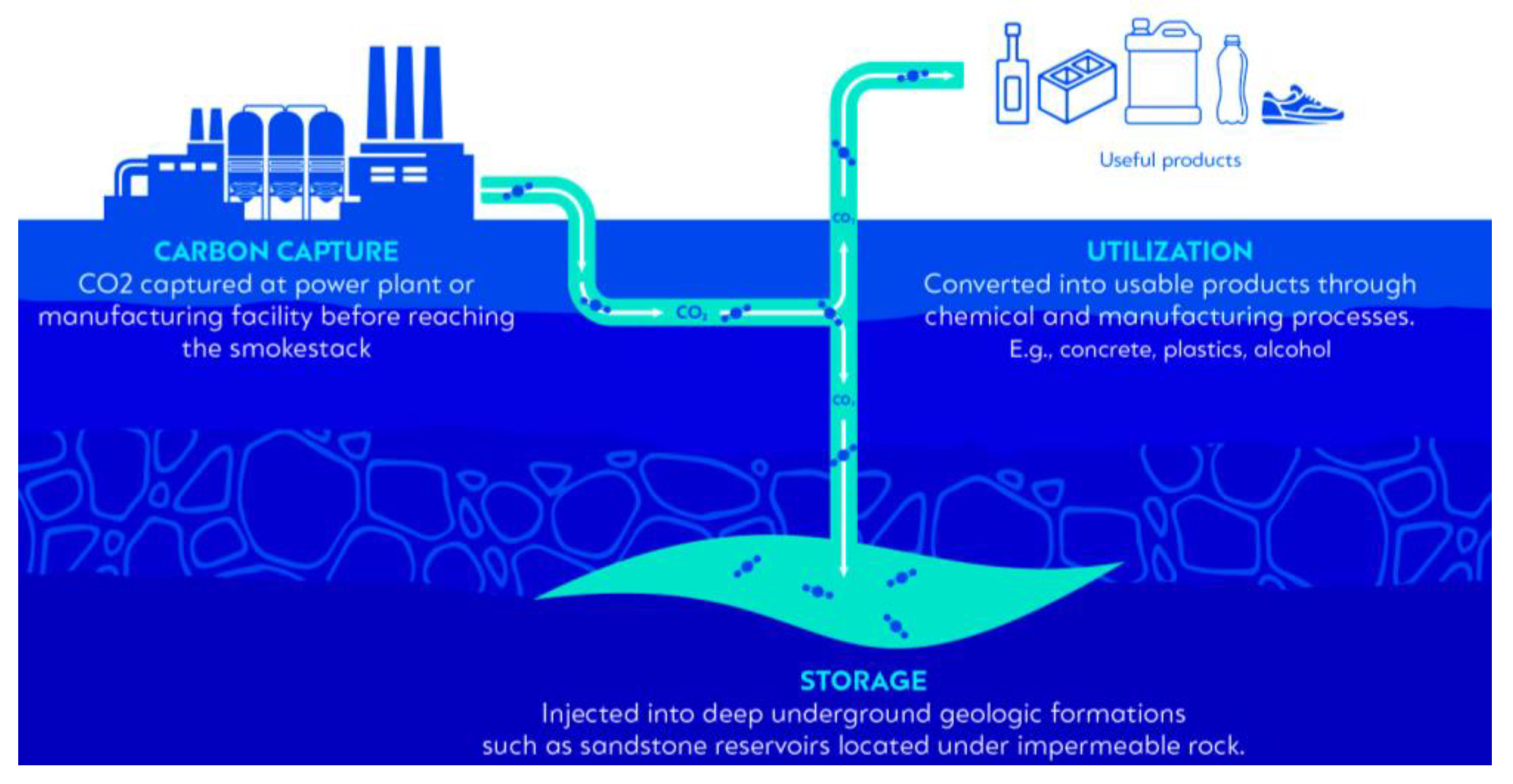
1.1. Carbon Capture, Utilization, and Storage (CCUS)

The development of carbon capture, utilization, and storage (CCUS) technology has become a major focus in recent years due to increasing concerns about CO2 emissions [1]. CCUS technology is widely regarded as one of the most important technological solutions for reducing carbon emissions, combating climate change, and transitioning to a carbon-neutral future [2,3,4,5]. According to the International Energy Agency (IEA), CCUS technology will contribute to the clean energy transition in several ways. Firstly, it will reduce emissions from existing energy infrastructure and industrial facilities that would otherwise emit 600 billion tonnes of CO2 over the next five decades. Secondly, it will reduce carbon emissions from the hard-to-debate heavy industry sector, which currently accounts for nearly 20% of total global CO2 emissions. Moreover, CCUS represents a cost-effective roadmap technology that will enable the rapid expansion of low-carbon hydrogen production, which is crucial to meet current and future demand. In fact, hydrogen demand is projected to increase sevenfold by 2070 in the context of the sustainable development scenario. By integrating CCUS technology, up to 40% of the hydrogen demand will be produced from fossil fuels and can be made carbon-free [6]. Therefore, it can be said that CCUS is an important technology to mitigate the large amounts of emissions from energy infrastructures and heavy industry and it acts as a bridging technology for the transition to alternative carbon-free fuels while maintaining a circular economy.
CCUS involves the indirect capture of carbon dioxide from emission-intensive facilities, such as power plants and industrial facilities that use fossil fuels or biomass, or directly from the atmosphere [7]. Since CO2 capture plays an important role in many industrial processes, commercial technologies for capturing or separating CO2 from flue gas streams have long been available [8,9,10,11]. These technologies include physical absorption and adsorption [12], which are the most popular capture systems today, while more complex capture methods include membranes [13,14] and chemical or calcium looping [15,16]. Once CO2 is captured, it is compressed and transported by two main methods. On a large scale, CO2 is transported via pipelines and ships, while over short distances and in small quantities it is transported by trucks or rails, albeit at a higher cost per tonne [7,17,18]. Subsequently, it may be utilized in a direct form as a heat transfer fluid (e.g., refrigerant) or yield booster (e.g., fertilizer) and it also may be used indirectly by converting CO2 into fuels, chemicals, or building materials through biological and chemical processes [19]. Alternatively, it may be permanently stored in underground porous formations [20]. Figure 1 illustrates CCUS technology options, highlighting both usage and storage pathways.
Although CO2 can be considered as valuable commodity and raw material, the global CO2 utilization is estimated at 230 million tonnes per annum [21] (Mtpa), corresponding to a fraction of approximately 1% of the annual global energy-related carbon emissions. In addition, CO2 conversion processes are still extremely energy-intensive technologies that are not yet ready for commercial-scale deployment [22]. Accordingly, it can be argued that the utilization of CO2 in the two forms (direct and indirect) does not yet constitute a main pillar in emission reduction, hereafter mitigating the impact of climate change.
The alternative CCUS technology option involves the permanent geological storage of captured CO2 in deep rock formations, thereby removing it from the atmosphere. Typically, a geological structure or formation qualifies as a carbon dioxide storage site when it incorporates certain geological characteristics. The fundamental conditions for a formation to be selected as a suitable carbon storage site are that it forms a pore unit of sufficient capacity to store intended CO2 volume and pore interconnectivity, allowing the injection of CO2 at the rate that it is supplied. In addition, the presence of an extensive cap rock or barrier located at the top of the formation is needed to retain the CO2 injected, prevent unwanted migration, and ensure long-term containment [23].

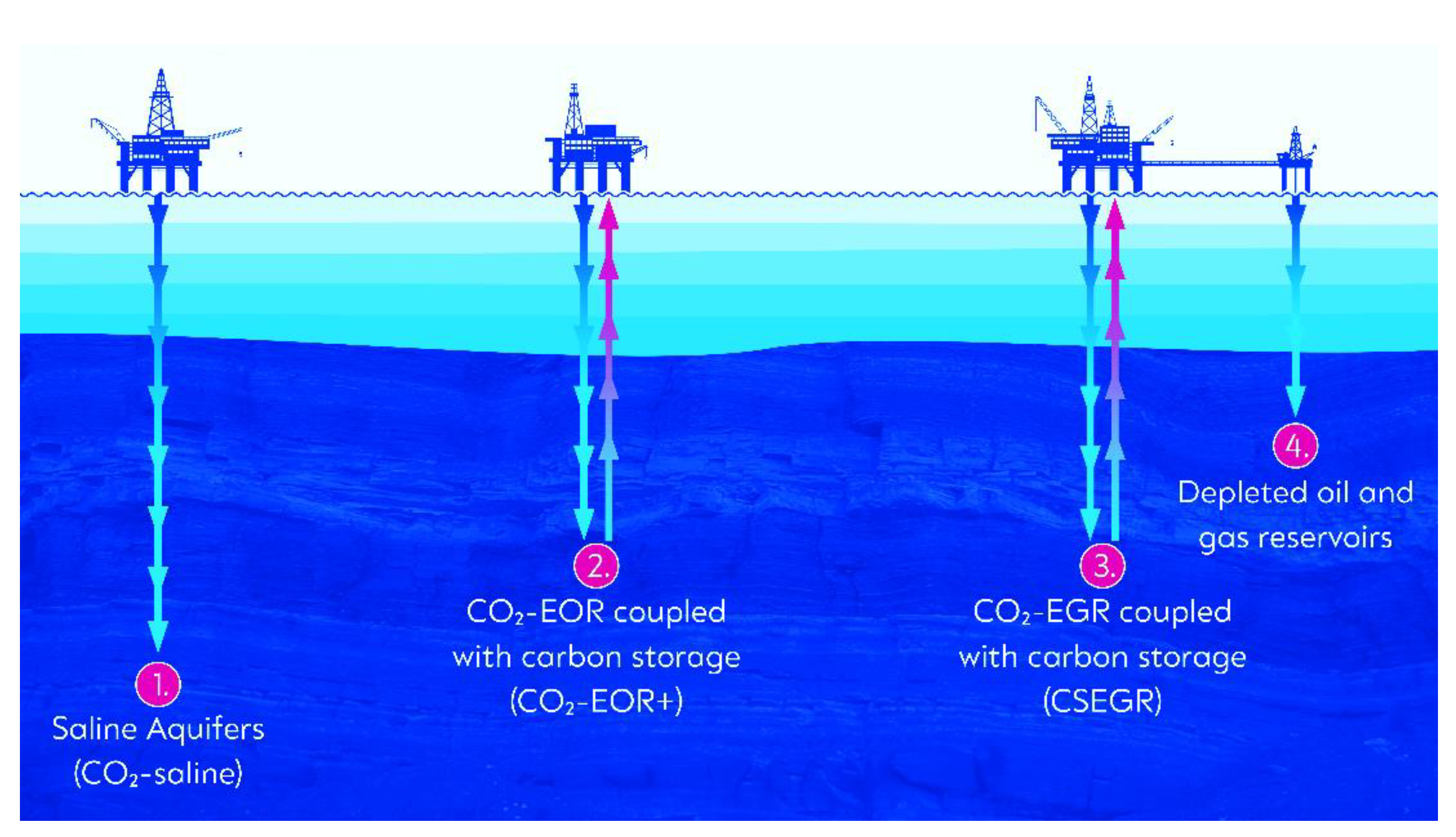
1.2. Geological Storage

The available geological storage options include storage in deep saline aquifers, which refer to any saline water-bearing formation (CO2-Saline) [24], storage with enhanced oil recovery (CO2-EOR/CO2-EOR+) [25], storage with enhanced gas recovery (CSEGR/CO2-EGR) [26], and storage in depleted oil or gas fields (CO2-depleted fields) that are no longer profitable in terms of oil and gas production [27]. Figure 2 depicts the four options for carbon storage in offshore environments. Although the figure focuses on offshore environments, it is worth noting that all of these options can also be applied onshore.
Deep saline aquifers are shown to exhibit the greatest storage potential, with an estimated global storage capacity ranging between 400 and 10,000 gigatonnes of CO2 [28]. The technical and commercial feasibility of CO2 storage in saline aquifers has been demonstrated in several large-scale commercial projects at various locations worldwide [29]. For instance, the Sleipner project in the North Sea is considered the first commercial CCS project in saline aquifers since 1996, with an injectivity capacity of approximately 1 million tonnes/year [30]. The Gorgon project in Australia is one of the largest operational CO2 sequestration projects, storing an average of 3.5 million tonnes of CO2 per year in the Dupuy saline formation [31].
The CO2-EOR technique involves injecting carbon dioxide into oil reservoirs for the purpose of enhancing oil recovery after depletion and a water flooding period, thus initiating miscibility effects that boost production [32,33]. This technique has been carried out on a commercial scale for almost 50 years and accounts for 20% of the incremental recovery achieved using EOR methods [34]. Nevertheless, since most of the injected CO2 remains trapped within the formation and, therefore, is not produced back to the surface along with the produced reservoir fluids, there is permanent underground CO2 storage. According to the IEA, today’s CO2-EOR injection process results in the injection of 300 to 600 kg of CO2 per barrel of oil in the United States, while an oil barrel emits about 500 kg of CO2 over its lifecycle (production, processing, transportation, and combustion). As a result, it is reasonably argued that CO2-EOR opens up the possibility that an oil barrel’s lifecycle may become carbon neutral and possibly carbon negative, depending on the boundaries of the analysis and the CO2 origin. For this reason, in 2015 IEA published one of the most detailed analyses of the feasibility of combining CO2-EOR with carbon storage by naming the process CO2-EOR+. Three scenarios to achieve carbon storage in CO2-EOR operations are identified, namely CO2-EOR+ conventional, advanced, and/or maximum recovery, depending on the physical and chemical characteristics of the oil in place [35].
Another promising CCUS storage option is carbon storage with enhanced gas recovery (CSEGR/CO2-EGR). This technique promotes the permanent sequestration of carbon dioxide and enhances the extraction of natural gas. CSEGR aims to inject CO2 into depleted gas reservoirs to repressurize and displace the remaining natural gas that is hard to exploit using conventional techniques [36,37]. The advantage of this method relies on the permanence of storage, as CO2 leakages are highly unlikely since the storage performance of the field has been proven [38].
Finally, depleted oil fields can be used to store carbon dioxide when the economic limit of the field has been reached either by primary recovery mechanisms or by secondary/tertiary recovery methods (e.g., CO2-EOR and/or CO2-EOR+). The major advantage of using partially or fully depleted oil and gas fields as carbon storage sites over others is the abundance of data and know-how acquired over the field cycle (exploration, exploitation, and production phases) [27]. In addition, the ability to reuse and/or repurpose existing oil and gas infrastructure (i.e., platforms and wells) for carbon storage reduces capital and decommissioning costs and minimizes investment risks and environmental impacts, thus forwarding the circular economy.

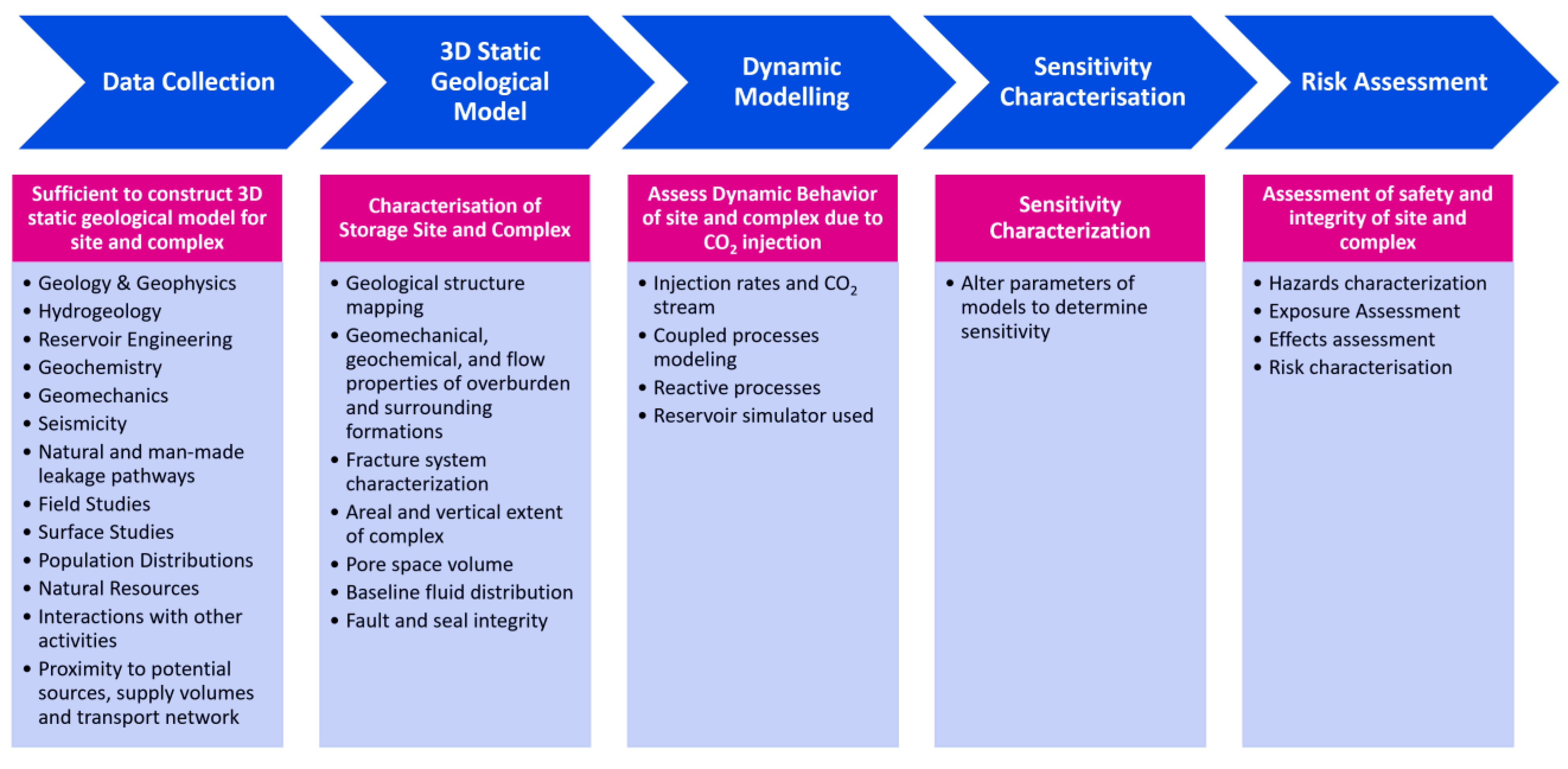
1.3. Injection Strategies: Reservoir Characterization and Underground Storage Policies

In order to deploy CCUS technology on a large scale in saline aquifers or hydrocarbon fields, a technically sound, safe, and cost-effective CO2 injection strategy must be developed while ensuring maximum storage capacity and site integrity [39]. Achieving this goal requires accurate characterization of the storage site and reservoir, which is a complex process that involves several steps. The process begins with a screening step to identify potential sites based on geologic and environmental criteria. Once potential sites are identified, a detailed site characterization is performed, which includes a comprehensive assessment of subsurface geology, geomechanics, hydrogeology, and other factors. Figure 3 provides an overview of the characterization and evaluation of the potential storage complex and surrounding area within the legal framework of Directive EU CCS (2009/31/EC), Annex I.
Although site and/or reservoir characterization is a crucial process in implementing carbon storage, it poses several challenges that must be addressed to ensure successful and safe carbon storage operations and designs. These challenges can be classified into three main clusters: a lack of subsurface data, uncertainty in subsurface parameters, and complex subsurface geology. Advanced data acquisition and interpretation techniques can mitigate the lack of subsurface data while updating subsurface parameters as new data becomes available and can address uncertainty in subsurface parameters. On the other hand, numerical simulation and modeling using computational fluid dynamics (CFD), perhaps coupled with reactive transport simulations to cover in situ geochemical reactions, can address complex subsurface geology. Reservoir simulations using CFD are, therefore, necessary to estimate with reasonable accuracy the field storage capacity and the behavior of the CO2 under reservoir conditions during all phases of the CCUS project (injection/operation, closure, and post-closure). Additionally, simulations are used to capture any CO2 leaks and/or migration to the surrounding area or the existing storage complex within a radius of at least 1 km. Therefore, a thorough reservoir characterization and numerical reservoir simulation tool can provide the means to understand the impact of different injection strategies effect on (1) the field dynamic storage capacity, (2) the CO2-entrapped fraction by each trapping mechanism active at both the microscopical and macroscopical scale, (3) the field and caprock pressures, and (4) the sweep efficiency and field integrity. This understanding can, therefore, help design a viable and technically competitive injection strategy that maximizes dynamic storage capacity while maintaining a reasonable risk assessment and monetary value.
Numerical approaches have revolutionized the simulation of carbon storage by capturing various mechanisms that can be encountered at the reservoir scale such as structural, dissolution, and residual trapping. These models can predict the extent and size of the CO2 plume throughout the CCUS project phases including injection, closure, and post-closure [40,41]. Although some modeling and computational issues are still under investigation, such as grid resolution on a range of processes that take place when CO2 is injected into a reservoir, several researchers have compared the performance of carbon storage simulations against field data. They demonstrated that, with minor calibrations and/or adjustment of simulation model parameters, a reasonable prediction of the storage performance of CO2 can be obtained. Xu et al. [42], Doughty et al. [43], Daley et al. [44], and Hovorka et al. [45] used vertical seismic profiling, cross-well seismic, and observation well data from the Frio experiment to confirm the simulated prediction performance of the plume distribution and migration. Doughty et al. [43] even demonstrated that reasonably accurate model predictions can be achieved with manual history matching. On the other hand, Singh et al. [45] performed a fine calibration of the relative permeability curves used in the North Sea Sleipner project simulation model. This resulted in a reasonably good fit of the predicted CO2 plume size and spreading performance of the CO2 with that observed in seismic profiles. Therefore, the developed CFD simulation techniques can be said to be mature enough to model large-scale carbon storage reservoirs with reasonable accuracy. Therefore, this provides a means to determine storage capacity, evaluate the performance under various injection strategies, and model the behavior of CO2 in the short and long term.
Additionally, reactive transport simulations that consider complex geochemical reactions are important for investigating the security of carbon sequestration, as carbon injection can cause geochemical alterations and deformations in various subsurface regions, including the caprock, storage formation, wellbore, and underlying water aquifers. These reactions depend on the mineral type, rock mineralogy, and brine composition. Dai et al. [46,47] thoroughly reviewed the key geochemical reactions and corresponding quantitative assessment methods that describe the associated sequestration capacity and safety, identifying uncertainties and technical gaps. Although geochemical processes have not received enough attention when it comes to modeling CO2 injection at the field scale, which is mainly due to the long timescale for reactions, which makes their potential effects ignorable during a relatively short time period (a typical injection period of 30–40 years), Soltanian et al. [48] performed a high-resolution numerical simulation study in a fully coupled multiphase flow and multicomponent reactive transport framework for the Cranfield CO2 injection pilot project. They showed that small changes in petrophysical properties can significantly affect migration in subsurface systems, but the impact varies depending on the dominant reactions and the geologic setting. Additionally, they emphasized that the proper consideration of boundary conditions and the accurate capture of domain geometry are important for simulation studies, especially in tilted domains where fluid flow may be influenced by gravity.
Although it is crucial to accurately model the evolution of CO2 plumes and in situ geochemical reactions, it is equally as important to establish fundamental subsurface engineering policies for safe and efficient carbon storage operations. These policies should form the basis for underground carbon storage application, in particular carbon injection schedules and/or well control strategies, and account for potential subsurface risks that can be encountered, long-term containment, and the technical viability of storage operations. For instance, handling the pressure build-up caused by CO2 injection constitutes a major risk that must be considered when injecting CO2 underground, thereby when designing the injection schedule of a given storage site. The concept of pressure management is not new in reservoir engineering, as the injection of fluids, such as water or gas, into hydrocarbon reservoirs to maintain field pressure in secondary recovery applications is a common practice applied for decades [48]. Nevertheless, unlike hydrocarbon reservoirs, when injecting CO2 into saline aquifers where the porous medium is already occupied with incompressible fluids (brine solution), pressure build-up takes place quite quickly which, if uncontrolled, may lead to high pressures that can fracture the caprock, reactivate faults, open natural or artificial conduits and channels that promote CO2 leakages, and even drive both CO2 and formation brine to shallow water-supply aquifers [49,50,51,52,53,54], as illustrated in Figure 4.
For instance, potential conduits for vertical CO2 movement in the form of fluid chimneys in the Utsira Formation at the Sleipner project were recognized, and sequential surveys were conducted to ensure that no excess of pressure resulted in CO2 migration to the upper layers [56,57]. Therefore, pressure management is one critical policy that must be accounted for when designing the injection schedule of a given storage site. Other policies correlate to the long-term underground containment of CO2 injected such as storage security, the integration of the CO2-EOR application objective to integrate carbon storage by maintaining a trade-off among two technically conflicting objectives, and ensuring high storage efficiency for CO2-EGR applications.

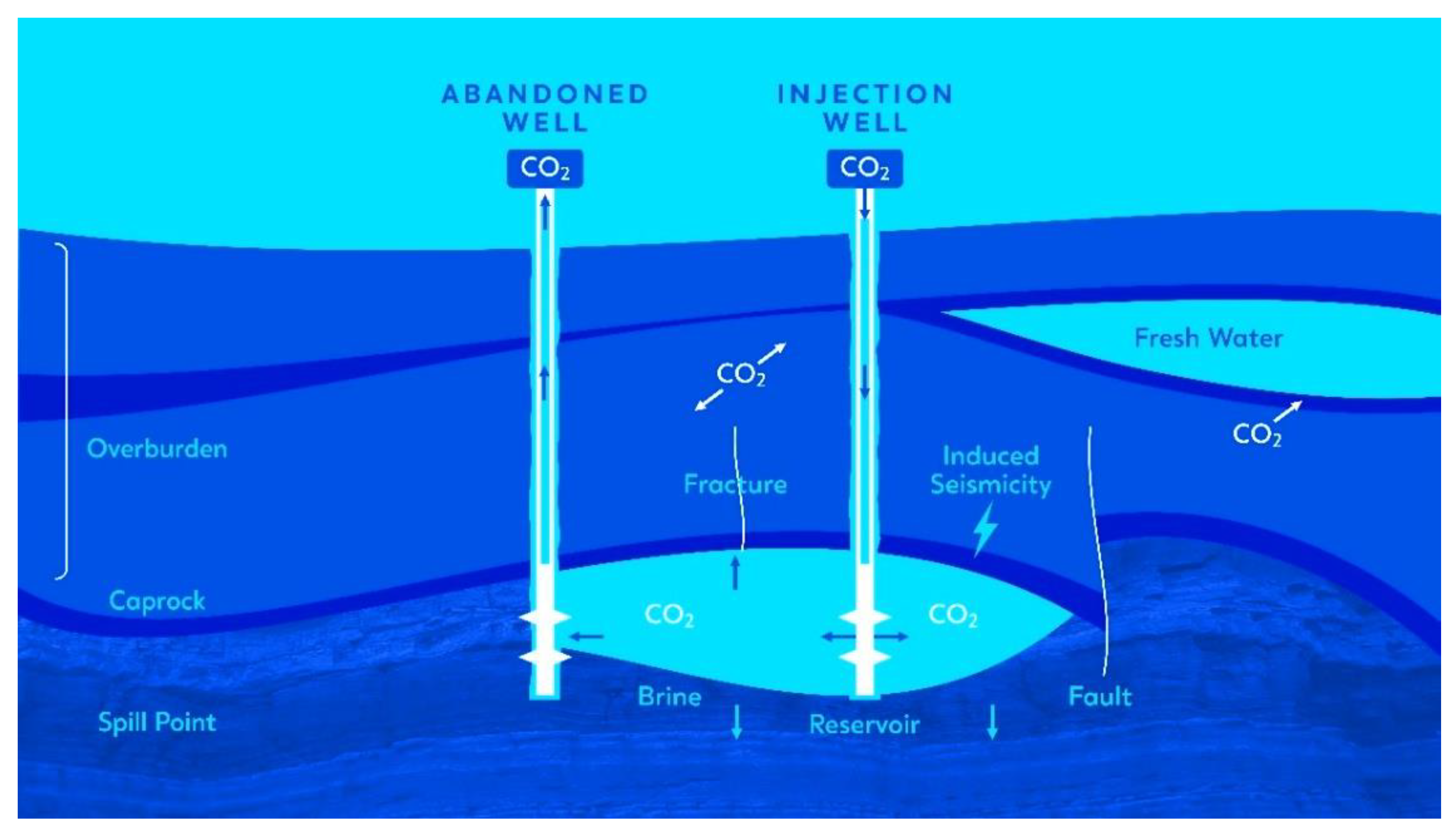
1.4. Injection Strategies: Challenges and Optimization Approaches

Effective implementation of subsurface engineering policies is crucial for the safe and efficient storage of CO2 in geological formations. However, it is important to note that the implementation of these policies can significantly limit the site operator’s ability to store significant amounts of CO2. For instance, the ability to store CO2 in saline aquifers can be dramatically reduced due to the pressure build-up encountered during the injection [58]. In such cases, the only controlling factors are the injection rates or wellhead pressure decrease. Furthermore, integrating additional technical policies, such as enhancing long-term containment and security, can further reduce the effective storage capacity of a given site. As a result, adopting one or more engineering policies when designing a CO2 injection strategy may result in a reduction in storage capacity, which can make it challenging for CCUS projects to reach the necessary economic threshold capacity required for cost recovery. This can potentially lead to project death during the final investment decision (FID) phase.
Moreover, this challenge is further compounded by various barriers facing the CCUS industry, such as high costs and a lack of price signals or financial incentives [59], which have limited the deployment of commercial-scale projects globally. According to the Global CCS Institute, as of 2022, there are only 30 commercial CCUS projects with a storage capacity of approximately 43 million per annum (Mtpa), as shown in Table 1. Therefore, a comprehensive and integrated approach to the design and implementation of subsurface injection policies, particularly for injection strategies, is needed to ensure the safe and efficient storage of CO2 while maximizing the storage capacity and commercial viability of CCUS projects.
One way to address this challenge is to balance engineering policies at the field scale to maximize the storage capacity of a given field without endangering site integrity and maintaining health, safety, and environmental standards. Additionally, an economic–technical compromise, or “tradeoff,” must also be maintained when designing the injection strategy to ensure the commercial viability of the project without scarifying site integrity and environmental and health and safety standards. Developing such an approach will enable commercial-level CCUS development that is both economically viable and sustainable over the long term by providing a framework that balances field-scale engineering policies and economic considerations with safety, environmental responsibility, and site integrity. This not only maximizes the storage capacity of a given field while maintaining health and safety standards but also provides a comprehensive framework that considers all relevant factors, making it a key tool in the successful deployment of CCUS projects.
To address the complexity of the problem at hand, optimization techniques are used when designing CO2 injection programs. However, the optimization of the injection schedule in the subsurface is not a trivial task and cannot be resolved accurately in the classical optimization framework by defining an objective function with analytic expressions to describe the technical policies that need to be considered. The reason is the nature of the problem that involves technical policy constraints, such as preventing migration of the CO2 to the surrounding area or outside the storage complex and maintaining pressure build-up below a given threshold (fraction of the fracture pressure) anywhere in the reservoir and near the caprock at any time during the injection phase. In addition, these injection policies depend on several factors, including the physical properties of the formation rocks, such as the local heterogeneity of reservoir regions. Furthermore, additional control factors must be included in the optimization of the well’s schedule when simultaneous development plans/schemes are being considered, such as producing brine from saline aquifers to reduce pressure build-up and potentially increase storage efficiency [60] and/or produce brine that is reinjected into the reservoir to improve the dissolution mechanism [61]. Things may become even more complicated when considering economic decisions that require trade-offs between costs and benefits (additional costs vs. additional CO2 storage capacity) that can be achieved under different development plans (brine production/recycling).
On this basis, several methods have been investigated in many studies to deal with the complexity and solve the optimization problem, arriving at a technically safe and economically viable injection schedule. These methods utilize both local and global optimization techniques combined with derivative-based or derivative-free approaches while considering various development schemes, such as brine production/recycling, and applying different technical and economic policies in the form of objective functions, boxes, or non-linear constraints [62,63,64,65,66]. For example, Shamshiri and Jafarpour [67] considered honoring the engineering policy of maximizing storage security; thus, the long-term containment of carbon storage in saline aquifers in an indirect fashion in their optimization model through the adoption of an objective function that aims to improve CO2 sweep efficiency using the BFGS algorithm [68] to obtain a technically sound injection schedule was possible. Alternatively, Cameron and Durlofsky [69] optimized the injection well’s location and injection plan, accounting for the same technical policy in their optimization model and considering the objective function that directly minimizes the long-term amount of mobile CO2 using a noninvasive, gradient-free Hooke–Jeeves direct search (HJDS) [70] method. Ultimately, these optimization techniques can help to balance engineering policies and achieve a maximum storage capacity of a given field while maintaining site integrity, environmental and health standards, and the commercial viability of CCUS projects.

1.5. Scope and Structure

In this work, we review carbon storage studies to provide a comprehensive review and classification of the key technical policies and factors that must be considered when applying CO2 geostorage, along with the computational optimization approaches that have been developed to date for large-scale carbon storage. The integration of technical policies into optimization techniques and the different modeling approaches used by various research groups, as well as the results obtained from designing in situ injection schedules in saline aquifers, are also discussed.
Our aim is to create a comprehensive reference guide for underground carbon storage. This review distinguishes itself from others by defining subsurface technical policies that must be followed and by providing a detailed analysis of the optimization techniques used to date for developing CO2 injection and well control strategies in saline aquifers, including how technical policies are integrated into these techniques.
The structure and content of this paper are organized as follows. In Section 2, we present the technical policies for geological CO2 sequestration and provide examples of how each policy can be applied through proposed development plans and optimized carbon injection schedules. In Section 3, we focus on geologic storage in saline aquifers, where we discuss the computational optimization techniques used for designing CO2 injection schedules and well control strategies from their first application until today. Finally, in Section 4, we summarize and draw conclusions based on the findings of our study. Overall, this paper aims to be a “one-stop shop” for subsurface technical experts, policymakers, and energy industry colleagues looking to gain a comprehensive understanding of technical policies, carbon storage development plans, and the application of optimization techniques for successful carbon injection scheduling in saline aquifers.

2. Key Subsurface Policies in CO2 Geological Storage: Outline and Application

Since the current portfolio of CO2 storage facilities does not adequately address the various geologic settings and commercial scales (i.e., >5 million tonnes CO2/year), several CCUS projects at different development stages face uncertainties concerning the extent to which potential capacity can be converted into effective capacity, confidence in the long-term safety of stored CO2 (against the likelihood that it will migrate and/or escape back into the atmosphere), and the practical joint application of CO2 storage and enhanced oil and/or gas recovery. Therefore, it is essential to establish and define sound technical policies and strategies to be applied for carbon storage in CCUS projects to facilitate commercial-scale CCUS development.
In this section, we discuss the key technical policies that need to be considered in the design and implementation of CCUS projects, particularly injection and well control strategies. Firstly, we refer to the pressure management policy that aims to avoid in situ overpressure while injecting CO2, preventing geomechanical complications, maintaining site integrity, and mitigating migration risks to the surrounding area or outside the authorized area. Secondly, we emphasize the importance of long-term containment carbon storage and define a policy that aims to enhance storage security by improving residual and solubility sequestration, which are low-risk short- to medium-term containment mechanisms that further reduce the likelihood of migration or escape of the injected CO2 back into the atmosphere.
Although storage in saline aquifers is the main topic in this work, a short description of the key subsurface policies that need to be followed in EOR, EOR+, and EGR projects is given for the sake of text completeness. Regarding the technical viability of carbon sequestration in conjunction with enhanced oil recovery, we discuss the practical need to honor the co-optimization of both objectives (carbon sequestration/EOR) in the design and implementation of CO2-EOR+ processes. This includes the injection schedule and field parameters so that CO2-EOR projects can serve as a means of mitigating the effects of climate change and reducing anthropogenic CO2. Finally, we discuss a storage efficiency policy in the application of the CO2-EGR process for a successful coupling of carbon storage and enhanced gas recovery application in natural gas reservoirs.

2.1. Pressure Management: Controlling Pressure Build-Up and Geomechanical Complications
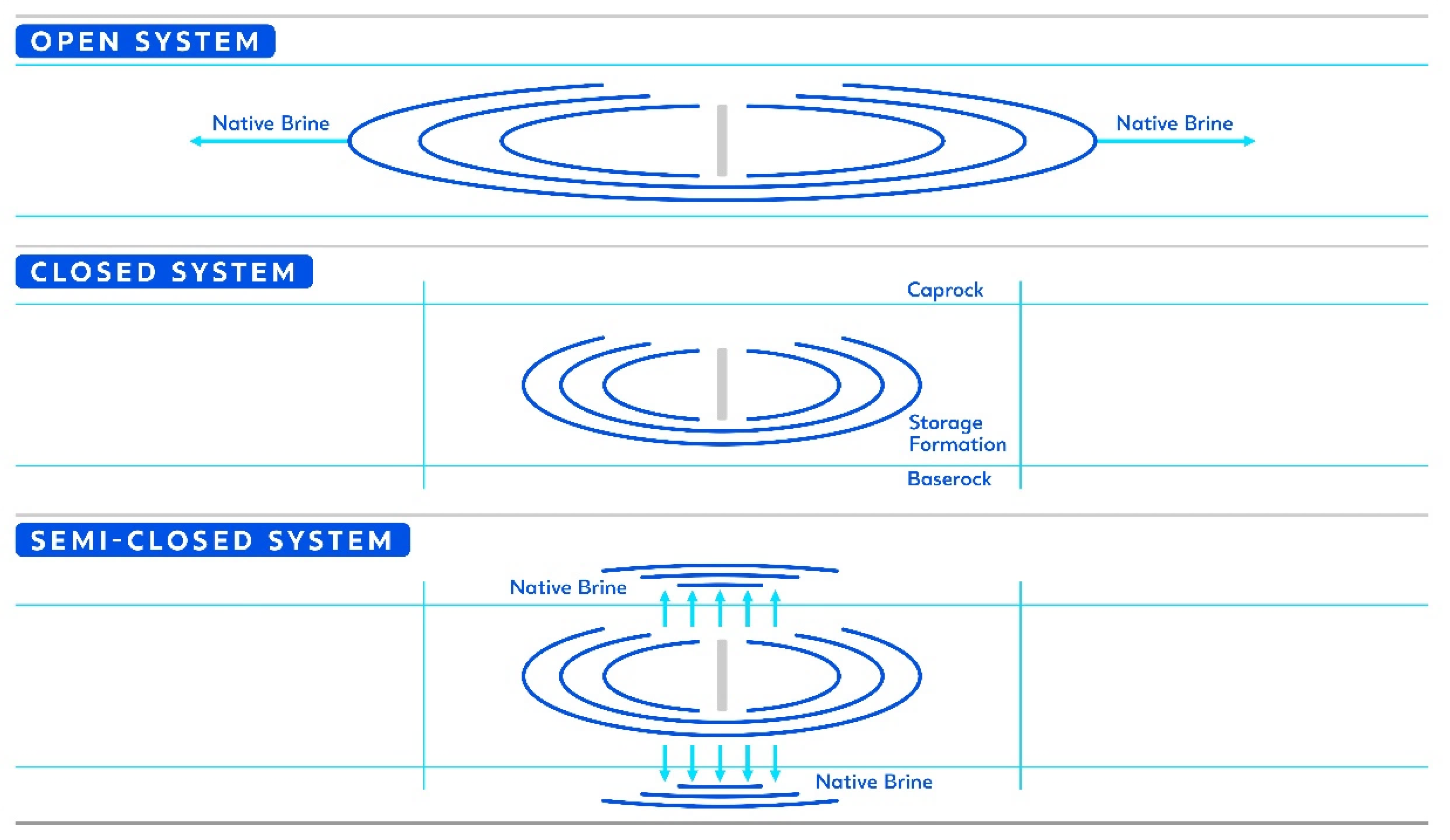
The commercial-scale deployment of carbon storage involves sequestering large amounts of carbon dioxide in the porous media of a host subsurface structure. The storage space for CO2 is created by the expansion of the formation rock pore space, together with a corresponding reduction in the volume of the native fluid due to compression. Although the storage system formation fluid can be displaced or withdrawn to facilitate the accommodation of injected CO2, pressure build-up in the host formation is still anticipated when deploying carbon storage on a commercial scale. Among other factors, reservoir pressurization response to CO2 storage depends mainly on the host formation boundary conditions, and the three storage systems illustrated in Figure 5 can be classified as:
(1)
Closed systems, where the storage formation is surrounded by impervious boundaries and blocked vertically by impervious sealing units.
(2)
Semi-closed systems, where the storage system is enclosed laterally by impervious boundaries but overlain and/or underlain by semi-previous sealing units.
(3)
Open system, where the lateral boundaries are too far to be affected by pressure disturbances [71].
The effect of pressure build-up in closed systems has a more significant impact on CO2 storage capacity than in open and semi-closed systems due to the absence of pressure bleed-off [71,72,73,74]. While closed systems do not present any environmental risk of brine leakage during CO2 injection, pressure build-up must be kept safely below the maximum pressure (fracture pressure) that can be tolerated by a given formation to preserve the mechanical integrity of the storage site from the tensile or shear failure of the caprock and/or reactivation of the existing fractures and faults [75]. On the other hand, modeling studies have shown that pressure build-up also limits the storage capacity of open systems. Elevated pressure may cause brine displacement into freshwater aquifers through localized pathways, such as leaky faults and wells [57,75,76], which could pose environmental risks. Meanwhile, reservoir pressurization is effectively reduced in semi-closed and open storage units due to the pressure bleed-off caused by brine migration into semi-sealing units and/or lateral brine displacement [77]. Based on the discussion above, it can be said that the effective storage capacity of the reservoir is not limited only by the pore volume of the formation rocks but also by the maximum permissible build-up pressure. Szulczewski et al. [78] have shown that the pressure constraint is the principal limiting factor for CO2 storage in the short term, while limited porosity prevails in the long term. The initial pressure build-up in the reservoir mainly depends on the properties of the formation rock such as porosity, permeability, anisotropy, pore compressibility, etc. [79,80], whereas these parameters are reservoir-dependent and uncontrollable [69].
Therefore, it is essential to formulate a technical and economically feasible development plan for CO2 storage based on site characteristics that optimize the CO2 injection rate maximize the efficiency of long-term storage while maintaining pressure build-up below the cut-off threshold, which is a fraction of the fracture pressure of the host formation (~90%). This avoids unwanted geomechanical complications [81].
To mitigate these issues and, therefore, comply with the pressure management policy, several researchers have proposed development schemes and plans that aim at extracting brine from aquifers to potentially increase the amount of CO2 that can be effectively injected and to control pressure build-up at saline aquifer storage sites. For example, Court et al. [61] and Buscheck et al. [62] demonstrated in synthetic models the significant benefits of pressure control through brine production. They showed that brine production had no significant effect on the conformational shape of the CO2 plume, as the latter depends on the characteristics of the storage formation. However, brine production comes with setbacks due to additional pumping, transportation, treatment, and disposal requirements, which increase costs. To address this, Birkholzer et al. [81] demonstrated that it is possible to reduce the amount of brine produced in CO2 storage operations with proper placement of the wells and optimization of their rates. Cihan et al. [82] applied this technique by addressing the optimization problem in a realistic example of the Vedder Formation in California, USA, minimizing the ratio of produced brine volume over the volume of injected CO2. Other researchers have attempted to optimize the CO2 injection schedule in saline aquifers while considering both alternatives (with and without brine production), along with economic profit constraints imposing that caprock fracture pressure cannot be reached at any time and placed in the reservoir. Santibanez-Borda et al. [60] engaged in a novel optimization strategy to maximize CO2 storage and pre-tax revenues in Cenozoic Sandstones of the Forties in the North Sea. They injected CO2 while simultaneously producing brine to control pressure build-up. More details about the optimization method applied and the results obtained will be given in Section 3 of the paper.

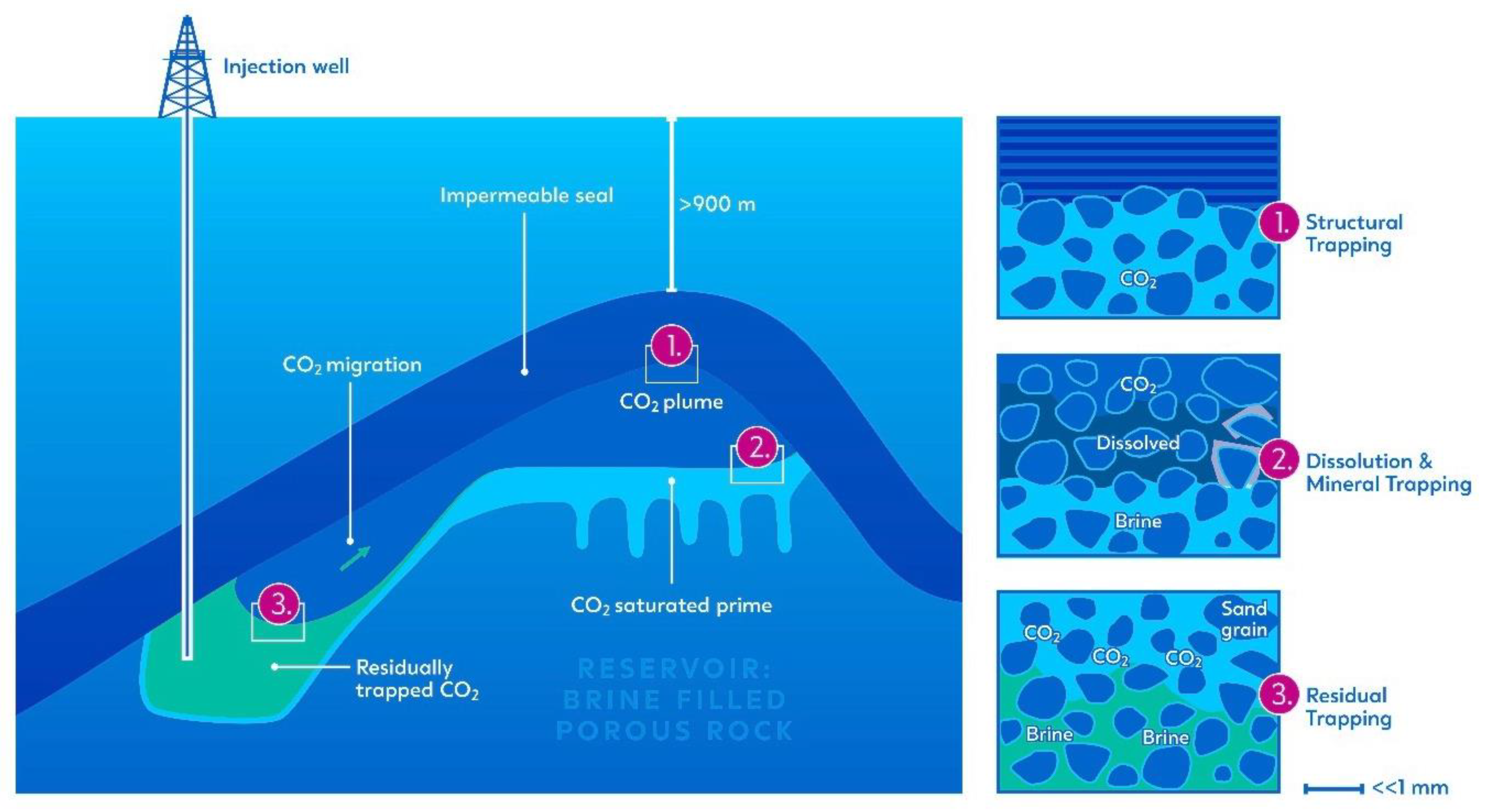
2.2. Geological Storage Security: Improving Residual and Solubility Trapping

To achieve geological storage, CO2 is typically injected as a supercritical fluid deep below a confining geological formation at depths greater than 800 m. A combination of physical and chemical trapping mechanisms is encountered, which are effective over different time intervals and scales [72,73] (Figure 6). Physical trapping occurs when CO2 is stored as a free gas or supercritical fluid and can be classified into two mechanisms: static trapping in stratigraphic and structural traps and residual trapping in the pore space at irreducible gas saturation. Additionally, CO2 can be trapped by solubility through its dissolution in subsurface fluids and may participate in chemical reactions with the rock matrix, leading to mineral trapping [83].
Since carbon storage’s primary purpose is to provide permanent and long-term underground CO2 storage, the safety and security features of each CO2 trapping mechanism encountered in underground formations must be considered. Storage security increases with reduced CO2 mobilization, making mechanisms immobilizing CO2 extensively researched to reduce the risk of leakage from potential outlets in the formation (e.g., fractures, faults, and abandoned wells) [84]. Solubility, residual, and mineral trapping are considered safe mechanisms. Solubility trapping provides a safe trapping mechanism because CO2 dissolved in brine (or oil) is unlikely to abandon the solution unless a significant pressure drop occurs at the storage site. Furthermore, when CO2 is dissolved in brine, the CO2–brine solution density increases, resulting in convective mixing, which acts to prevent buoyant CO2 flow toward the caprock [85,86,87]. Residual trapping is also recognized as a safe trapping mechanism as it represents the fastest method to remove CO2 from its free phase with timescales in the range of a few years to a few decades [88,89,90,91]. Within its displacement in the formation, the front and tail of the CO2 plume undergo drainage and imbibition saturation-dependent processes, leaving traces of residual gas trapped in the rock pore spaces. Over timescales of hundreds of years, dispersion, diffusion, and dissolution are expected to minimize residual CO2 concentration [92]. Mineral trapping of CO2 occurs when dissolved CO2 combines with metal cations, mainly Ca, Fe, and Mg, resulting in the precipitation of carbonate minerals. The effectiveness of this type of trapping is determined by several factors, including the availability of non-carbonate mineral-derived metal cations in the formation of brine, the rate of carbonate and non-carbonate mineral dissolution in the presence of CO2 and resulting solution pH, and the conditions necessary for secondary mineral precipitation, such as the degree of supersaturation and availability of nucleation sites [93]. Mineral trapping is generally considered to be the most stable and secure of the four but is very slow in typical sedimentary rocks, with timescales of centuries or millennia [94]. Figure 7 provides a schematic microscopic view of the porous media, illustrating the primary trapping mechanisms encountered in storage formation.
Residual gas, dissolution, and particularly, mineral trapping mechanisms, share a relatively low contribution to underground CO2 storage when compared to structural trapping over a typical operational injection period of 30 years [88,95,96]. Although mineralization is the safest trapping mechanism, it is a very slow chemical process that can take hundreds to thousands of years, while solubility and residual trapping are considered two short-term and low-risk mechanisms for safe CO2 storage. Therefore, properly designing the CO2 injection schedule and storage development plan can optimize these mechanisms. This policy is essential to ensure the safety and security of long-term containment of underground CO2 storage.
Although the main difficulty of implementing this policy is that the predominant upward buoyancy-driven displacement of CO2 limits the horizontal access of the CO2 plume to the fresh brine of the aquifer, most studies anticipate this problem by considering different strategies, which are combined to apply computational optimization. Leonenko and Keith [97] investigated the role of brine injection on top of a CO2 plume in accelerating the dissolution of CO2 in formation brines. They found that such a technique could significantly improve CO2 solubility at the aquifer scale and concluded that reservoir engineering techniques could be used to increase storage efficiency and possibly reduce the risk of leaks at a relatively low cost. Kumar [98] applied an optimization approach to minimize structurally trapped CO2 in heterogeneous two-dimensional models by simulating 10 years of injection and 200 years of equilibration. In one example, they showed that the optimization decreased the likelihood of structural trapping by 43% compared to the base case. Similarly, Hassanzadeh et al. [99] studied the introduction of brine injectors into saline aquifers and showed that the injection of brine increased the rate of dissolution of carbon dioxide in aquifers, enhancing the dissolution trapping mechanism. They also proposed a reservoir engineering technique to optimize the location of the brine injectors to maximize the injection rates. In 2009, Nghiem et al. [100] found that optimal control of a water injector placed above a CO2 injector enhances residual and solubility trapping. In another study, in 2010, Nghiem et al. [101] optimized the location and operating conditions of a water injection well located above the CO2 injector and applied a bi-objective optimization approach to quantify the compromise or trade-offs between the optimization of residual and dissolution trapping. In turn, Shafaei et al. [102] studied the co-injection of carbon dioxide and brine into the same well by injecting brine in the well’s tubing and CO2 using the annual space between the tubing and the well’s casing, making it possible for the injection to be achievable at lower wellhead pressure, thus reducing compression costs.
On the other hand, Rasmusson et al. [103] found that the simultaneous injection of CO2 and brine, as well as the use of a water-alternating gas (WAG) scheme, had a beneficial effect on both residual and solubility trapping. In a recent study, Vo Thanh et al. [104] compared continuous CO2 injection against a WAG injection scheme and they demonstrated that the effectiveness of the WAG procedure in enhancing both trapping mechanisms was higher compared to continuous CO2 injection. For their analysis, they considered the impact of reservoir heterogeneity by running WAG scenarios on 200 geological realizations of the aquifer. Other proposed methods to reduce buoyant CO2 storage and eliminate the risk of buoyant migration involve surface dissolution, which aims to dissolve CO2 in brine extracted from the storage formation and then inject the fully saturated CO2 brine back into the storage system [105]. Other studies on surface dissolution are also involved in finding an optimal design of the injection and extraction strategy [106]. It should also be noted that surface dissolution reduces the degree of pressure build-up during injection and eliminates the displacement of brine [105,106]. Therefore, optimizing CO2 injection schedules, well control strategies, and implementing an effective storage development plan are critical for enhancing long-term containment and storage security through improved solubility and residual trapping.

2.3. CO2-EOR Carbon Storage Compliance: Joint Co-Optimization

Traditionally, CO2-EOR operations focus on maximizing oil production, with CO2 storage considered a secondary priority due to the cost–benefit imbalance of purchasing CO2 for enhanced oil recovery projects. Oil and gas operators seek to reduce the amount of CO2 needed to sweep the reservoir, leading to technical conflicts in designing operating parameters that can simultaneously achieve high recovery and high CO2 sequestration. While carbon storage has become an additional revenue source for operators due to the prevailing carbon tax regimes, such as 45Q in the United States, studies have shown that the tangible economic benefits of EOR often outweigh those of carbon storage, especially given the costs and challenges of implementing carbon sequestration at a commercial level, as this dispute ends in favor of oil recovery [107,108]. As a result, design parameters for CO2-EOR+ projects must be redefined to optimize CO2 storage volume while maximizing underground permanent CO2 storage at the end of the field lifecycle without sacrificing additional oil revenue. To achieve this goal, it is necessary to adopt a co-optimization engineering policy, meaning that design parameters of a given storage site development plan (e.g., carbon injection strategy) must be selected to simultaneously achieve desirable oil recovery while ensuring the best achievable amount of carbon stored underground.
Many technical studies address the co-optimization of oil recovery and CO2 sequestration in CO2-flooded EOR processes, and this conflict can be resolved in the form of a tradeoff. In 2000, Malik and Islam [109] studied various phenomena affecting oil recovery and carbon sequestration in the Weyburn field in Canada using reservoir modeling. They discussed technical conflicts involved in achieving optimal operating conditions for the simultaneous objectives of higher oil recovery and higher CO2 storage and proposed the use of horizontal injection wells to jointly optimize both objectives. Jessen et al. [110] also highlighted the need for the proper design of injection gas composition and well completion to jointly optimize oil recovery and CO2 storage.
Other researchers have investigated the co-optimization problem of CO2-EOR and CO2 storage, i.e., CO2-EOR+ reporting various development strategies/plans that affect oil production, carbon storage, and other effects without considering a specific objective function [110,111,112,113,114,115,116,117,118,119,120,121,122]. Meanwhile, in the absence of a direct relationship on how to achieve the technical strategy of co-optimizing CO2 EOR and carbon storage in practice, a second group approached this difficulty by explicitly considering maximizing oil recovery, carbon storage, or a weighted combination of the two objectives using injection strategy techniques [123,124,125,126,127,128,129,130]. Furthermore, a third group of studies considers the economic aspects in the application of co-optimization of CO2 EOR and carbon storage to honor the co-optimization policy by explicitly considering the maximization of the net present value (NPV) of the project profit or some related performance parameters [131,132,133,134,135,136,137,138,139,140].

2.4. Displacement Control: Sweep Efficiency Performance Control in CO2-EGR Applications

CO2 storage with enhanced gas recovery (CO2-EGR/CSEGR) promotes natural gas production while permanently storing CO2 underground in gas reservoirs. Although natural gas reservoirs are primarily composed of methane (>95%), CO2 and CH4 also exist in a gaseous state and are mixable under atmospheric conditions. However, the physical properties of the two components (CO2 and CH4) differ significantly at typical reservoir thermodynamic conditions ( µ CO 2 ~ 2 µ CH 4 , ρ CO 2 ~ 2 ρ CH 4 ) [26]. The original concept of CO2-EGR was first proposed by van der Burgt et al. in 1992 [141] and, since then, numerous numerical simulation studies have demonstrated the technical feasibility of carbon storage with enhanced gas recovery. For example, Oldenburg et al. [142] carried out 2D model simulations of the injection of CO2 into a depleted natural gas reservoir under isothermal conditions and homogeneous reservoir properties (porosity 0.35 and permeability in the Y-Z directions 1.0 × 10⁻¹², 1.0 × 10⁻¹⁴ m2). In two simulation scenarios (Scenario I: reservoir pressurization scenario: CO2 injection for 10 years with no CH4 production, Scenario II: CO2 injection with simultaneous CH4 production), they showed that 99% pure CH4 can be produced for about five years in Scenario I with a very high CH4 production rate. Similarly, 99% pure CH4 can be produced for about five years in Scenario II in conjunction with CO2 injection, but the methane production rate is lower than in Scenario I.
Meanwhile, several simulation studies have revealed that CO2 preferential flow pathways can easily form due to reservoir heterogeneity, which can compromise CO2-EGR performance. For example, Oldenburg and Benson [38] extended the analysis of Oldenburg et al. by accounting for formation heterogeneity and applied the log normal distribution in the Y-direction without correlation in the Z-direction. Their work showed that heterogeneity in the formation led to preferential flow paths for injected CO2, with such a phenomenon being favorable for injectivity and carbon sequestration, allowing the storage of larger quantities of CO2. However, preferential flow also resulted in early breakthroughs and, therefore, affected the application of enhanced gas recovery. Rebscher and Oldenburg [143], in turn, used a 3D grid model to investigate, in detail, the application of CSEGR in the Salzwedel-Peckensen natural gas field in Germany and demonstrated for the base case scenario that CO2 injection sweeps CH4 toward the production well, with breakthroughs occurring in the unit with the highest permeability due to preferential flow paths. Similar results were obtained by other researchers [143,144,145].
To address this problem, it is crucial to design the CO2-EGR process with parameters (e.g., CO2 injection schedule, well location, etc.), that allow for the greatest storage capacity and highest natural gas recovery. Maintaining high sweep efficiency by delaying CO2 breakthroughs and stabilizing the displacement process is a critical subsurface engineering policy that must be considered during the design implementation of CSEGR applications, particularly in the injection plan or/and well control strategies.
To honor this engineering policy, researchers have investigated several strategies to delay CO2 breakthroughs and stabilize the displacement process, such as the effect of water injection and formation water in high permeability strata by blocking the fast flow paths and thus promoting CO2 dissolution [37,145,146,147]. Others have examined the effects of CO2 injection time on CSEGR performance [36,148]. Moreover, Hussein et al. [149] showed in a simulation study that the CO2 injection rate is a key parameter in CSEGR along with the injection timing as it plays an important role in representing the optimal injection rate strategy. The locations of the CO2 injection wells and the natural gas production wells are also two other critical factors of the injection strategy in CSEGR implementation, as shown by Hou et al. [150]. In addition, Liu et al. [151] highlighted the impact of injection/production well perforation, whereas other studies considered the optimization of CO2 injection strategies in CSEGR applications [152,153].

3. Optimization of CO2 Injection and Well Control Strategies for CCUS Application in Saline Aquifers

Although deep saline aquifers have enormous storage potential for CO2 sequestration, assigning an optimal, technically sound injection schedule of CO2 presents significant engineering challenges. This is due to the need to meet multiple objectives and comply with technical policies, as well as handle limited knowledge of geologic characterization caused by large uncertainties in capacity, injectivity, and containment. Additionally, there is little project experience as opposed to depleted oil or gas reservoirs.
To address these considerations, mathematical optimization tools are utilized to guide injection planning and operations while minimizing computational costs. These tools explore the range of likely outcomes, particularly in predicting long-term storage security with CO2 migration over hundreds of years after operations end. Optimization has been used for over 15 years in the application of carbon storage in saline aquifers, and various optimization tools and models have been employed to fulfill objectives and adhere to policies. In this section, we review and analyze the application of various modeling and optimization techniques for developing a technical injection strategy in saline aquifers, as summarized in Table 2.
It is worth mentioning that while the field of AI techniques for optimizing CCUS operations in saline aquifers is still relatively new, it has a promising potential for improving the efficiency and effectiveness of CO2 sequestration. You et al. [154] demonstrated the fast, robust, and stable application of a machine learning-assisted optimization workflow for co-optimizing CO2 storage, CO2-EOR performance, and project economics in the Pennsylvanian Upper Morrow sandstone reservoir in the Farnsworth Unit (FWU). Therefore, it is expected that AI techniques will be increasingly employed for such applications in the CCUS industry in the future.
The optimization of CO2 injection strategies in saline aquifers was first applied by Kumar in 2007 [98]. Using the conjugate gradient method implemented by Yeten et al. [155] and treating the commercial simulator as a black box for determining the objective function values, Kamar ran an optimization routine to determine the optimal well inlet valve/injection rate setting that minimizes gas saturation in the top layer of an aquifer model. The adopted objective function to be maximized accounted for the residual trapped CO2, honoring the storage security engineering policy. They considered a moderate heterogeneous (average permeability 1100 mD) two-dimensional vertical cross-section of an aquifer gridded into 16,000 blocks, and they simulated a 10-year injection period followed by a 200-year equilibration phase. The injection rates were updated five times during the course of the injection period to allow for variability in the injection schedule. Despite its simple formulation, the attempted optimization led to a significant reduction in the amount of structurally trapped CO2 compared to the base case scenarios. In the case of a single well, the optimization solution resulted in a 16% reduction in the CO2 saturation at the top of the aquifer compared to the base case, while in the case of two and three wells, the optimized solution resulted in a reduction in free gas saturation at the top of the aquifer with more residual trapping for the three-well case, highlighting the need for the optimization of both the well’s injection rate and the number of wells. In addition, Kumar also investigated the effects of the number of optimization time steps, capillary pressure, and heterogeneity, as well as the effects of the initial settings on the optimization results.
Nghiem et al. [100] showed that residual gas and solubility trapping can be accelerated and enhanced by injecting water above the perforations of the CO2 injector. They maximized an objective function that accounted for the trapping efficiency index, which involved both residual and solubility trapping indices, and they applied the procedure developed by Yang et al. [156] to determine the optimal water injector settings (depth, rate, and injection duration) for homogeneous aquifers while limiting the optimization/decision variables to a technically feasible range to honor pressure management policy. They showed that water injection at a greater depth in the case of a low permeability aquifer favors residual gas trapping, while in the case of high permeability formations, water injection at a shallower depth favors solubility trapping. In a later work, Ngheim et al. [101,157] studied the interaction of the two trapping mechanisms (solubility and residual gas) and concluded that they are competing and occur simultaneously during injection and post-closure. By using Pareto-optimal solutions with a bi-objective optimization approach, they were able to quantify the tradeoffs between residual trapping and dissolution trapping optimization.
Since the density-induced upward movement of gas or supercritical CO2 hinders both solubility and residual trapping mechanisms by preventing lateral migration of the plume in the reservoir, Shamshiri and Jafarpour [67] proposed a method to control the injection schedule and thereby improve sweep efficiency and increase the contact of injected CO2 with the in situ brine. They introduced pseudo-production wells with insignificant production rates and negligible effect on the overall flow regime to compute hypothetical breakthrough curves. They showed that uniform sweep efficiency can be achieved by minimizing an extra term in the objective function, which penalizes the difference in CO2 production rates among the pseudo-producers. As a delayed breakthrough (at constant total CO2 injection volume) implies better sweep efficiency, a second term was included in the objective function to minimize the total field CO2 pseudo-production, thus delaying the breakthrough time. Meanwhile, to apply the developed formulation while honoring other engineering policies (e.g., keeping injection pressure below aquifer fracture pressure), they applied the BFGS algorithm to the flow equations in conjunction with equality and inequality constraints (e.g., limiting the bottom hole pressure of injection/production wells) imposed to the control variables so as to maintain a technically sound injection schedule. They illustrated the effectiveness of the proposed method using two heterogeneous models, the Synthetic 3D and the PUNQ-S3 benchmark models. Comparing the results of the proposed sweep efficiency optimization technique against the application of direct optimization of the total stored CO2 in the aquifer and the base case simulation scenario (uniform distribution of well injection rates), a significant improvement in both residual and solubility trapping was shown, with an arrival time of CO2 delayed by nearly 25 and 50 years, respectively, for each simulation model, thus demonstrating that their sweep efficiency optimization is the most effective technique for improving both solubility and residual trapping. In a more recent work, the authors [84] modified the objective function by eliminating the second term of the objective function. Their new results showed that although a uniform sweep improves the storage potential in the aquifer, its storage performance is not as good as directly maximizing the stored CO2 in the aquifer. They noted that sweep efficiency optimization does not account for the storage potential of both low- and high-porosity zones in the reservoir, whereas maximization of the stored gas takes advantage of available storage volume irrespective of the efficiency of the resulting sweep. Considering the results of synthetic model simulations, the volume of dissolved gas after 300 years (10 years of injection and 290 years of equilibration) increased from 12% of the total gas injected (TGI) in the base gas to 18% when optimizing sweep efficiency, and it was 25% when the stored gas volume was optimized. In addition, the total amount of CO2 trapped as residual gas is approximately 40% of the TGI in the base case, 45% when sweep efficiency is optimized, and 50% when the stored gas is optimized. Through further modification of the objective function and optimization work, they confirmed the effectiveness of the controlled injection strategy in diverting CO2 plumes from aquifer regions with potential pathways (e.g., conduits/faults), thereby increasing CO2 storage security. Cameron and Durlofsky [69] extended previous studies by optimizing the locations and injection schedule of multiple CO2 injectors with the goal of minimizing the long-term amount of mobile CO2 in a saline aquifer. Using a noninvasive, gradient-free Hooke–Jeeves direct search (HJDS) method with convex inequalities and constraints on the decision variables, the optimization determined the location and injection schedule of four horizontal CO2 injection wells, with the constraint that they must be situated in the central 10.9 km2 region of a 232 km2 heterogeneous saline aquifer model. Because HJDS is a local optimization technique, they conducted three optimization runs using different initial estimates for the well’s placement parameters and the same initial estimate for injection rate parameters (equal fraction), yielding different results, thus suggesting the presence of multiple local optima. The results of the best-achieved solution showed that the dissolution and residual trapping were improved by 7% and 5%, respectively. Furthermore, they investigated cases of brine cycling where a certain volume of brine was produced and re-injected into the formation above the CO2 injection sites. Varying the volume of the brine cycle and including additional parameters defining the timing, duration, and pumping fraction of the injection event to the optimization decision variables, they showed that increasing the volume of the brine cycle decreases the optimized mobile CO2 fraction, with optimization results showing that the more brine injected, the lower the mobile fraction in the system.
Zhang and Agarwal [158,159] applied a genetic algorithm-based optimizer in conjunction with the TOUGH2 numerical simulator to optimize the injection schedule for a water-alternating gas injection system (WAG). To increase CO2 sequestration efficiency and reduce CO2 plume dispersion, they considered the reduction in CO2 plume migration (compared to migration under constant CO2 injection) normalized to the total amount of water injection as a fitness function to evaluate the efficiency of a particular WAG operation. Using CO2 and water injection rate, WAG, and cycle duration as decision variables, they applied the optimization technique to a vertical injection well modeled at the center of a hypothetical cylindrical salt formation and to a horizontal well modeled in a radical section of a hypothetical thin aquifer. For both well configurations, they showed that optimized WAG operations resulted in a nearly 14% reduction in CO2 migration, with lower average gas saturation in the uppermost layer of the aquifer compared to constant injection operations. However, they noted the risk of increased injection pressure in WAG, which can endanger formation integrity, and they suggested that horizontal well configurations are better for WAG in three ways: higher migration reduction per unit of water injected, lower free gas saturation, and lower pressure response. To mitigate the increase in injection pressure above the formation threshold, the authors extended their own previous work in which they determined the optimal injection strategy for horizontal well configuration, which resulted in injection pressure management that optimized aquifer storage efficiency while accounting for pressure build-up policy [160]. Using the CO2 injection rate as the decision variable and the threshold pressure (caprock pressure) as the constraint, the optimization of the injection was performed using a modified version of well’s injectivity as a fitness function in conjunction with the Bezier curve to describe the CO2 injection rate in the form of a time-dependent continuous function.
Cihan et al. [82,161] presented a differential evolution algorithm for optimizing well placement and brine production rates to control pressure build-up in saline aquifers. Minimizing the objective function, which consists of the ratio of the extracted fluid (brine) to that of the injected fluid (CO2), the selection of brine production rates is evaluated under the constraints that no CO2 breakthrough occurs at the production wells and the maximum pressure build-up must not exceed the pressure threshold. They further compared the results of the gradient-free constrained differential evolution (CDE) algorithm against a gradient-based, constraint optimization technique, the sequential quadratic programming (SQP) algorithm, for a simple pressure management system. They showed that the results of the CDE algorithm agree very well with the SQP method; however, the number of objective function evaluations for the CDE algorithm is much larger than for the SQP algorithm (1620 for the CDE/12 for the SQP). Furthermore, by coupling the CDE optimization algorithm with a numerically averaged heterogeneous aquifer model with a critically stressed fault near the injection zone, they demonstrated successful estimation of optimal rates and locations for CO2 injection and brine production wells that meet multiple pressure build-up constraints.
Tarrahi and Afra [162] extended the work of Shamshiri and Jafarpour and proposed a formulation to optimize CO2 sequestration by controlling the operating conditions of CO2 injection wells to promote uniform CO2 dispersion in the aquifer formation. While Shamshiri and Jafarpour equalized the rates of pseudo-production wells or representative cells, Tarrahi and Afra promoted uniform CO2 dispersion and breakthrough time equalization of equidistant pairs of cells from CO2 injection wells instead of pseudo-production wells, as in the work of Shamshiri and Jafarpour 2012, to enhance solubility and residual trapping of injected CO2. Taking into account the top layer of the PUNQ-S3 benchmark model (263 equidistant pairs) with 6 injectors, they showed that by using a gradient-based optimization technique, the total CO2 stored in the aquifer in the form of residual and dissolved trapping increased by about 11% in the optimized case compared to the base case.
Babaei et al. [65] illustrated the use of an evolutionary optimization algorithm to find the optimal distribution of the total CO2 injection rate across eight existing wells in the heterogeneous storage complexes at the Forties and Nelson reservoirs in the North Sea, with the single and multiple objective functions of minimizing the fraction of CO2 that is in a free gaseous state outside the licensed regions and maximizing the amount of dissolved and residual trapped CO2. Using a fine-scale model (FM: 840 × 640, grid: 50 m) and three coarser ones in the x and y directions (CM1: 420 × 318 grid: 100 m, CM2: 280 × 211 grid:150 m, CM3: 210 × 158 grid: 200 m), they tested the optimization of CO2 injection strategies on all models to evaluate the reliability of an upscaled model in the optimization strategy so as to identify the optimal grid resolution that represents a successful trade-off between static model accuracy and computation time. The convergence results of the single-objective optimization (only minimizing free CO2 gas) showed that the mobile CO2 reduction using the FM is 21% lower than the base case scenario. Results of the CM3 exhibited a relative error of 5%, with the main difference being the allocation of injection rate between wells, while this error was reduced to about 1% in the CM1 and CM2 cases, thus indicating affordable errors when using coarser grids. For multiobjective optimization, results indicated a conflict between the two objective functions without significant deviations in CO2 stored, as coarse resolution grids led to a systematic overestimation of the CO2 storage maximization objective.
Stopa et al. [163], in turn, developed and applied an optimization technique to minimize the risk of CO2 leakage by minimizing the volume of free CO2 gas at the top of a heterogeneous aquifer. Using a genetic algorithm (GA) and the particle swarm optimization (PSO) technique, they determined optimal CO2 injection well placement and time-varying injection rates that minimized leakage risk. They compared the benefits of the GA and PSO for two cases involving only structural and residual trapping in the aquifer. The first case involves optimizing the location of five injection wells in a heterogeneous aquifer for a constant injection rate. It is shown that both methods converge to the same results, namely a reduction in the CO2 content in the top layer from 23.77% in the base case to 12.71% after 80 years (10 years of injection and 70 years of observation). However, the comparison of the number of simulation runs of both methods shows that the GA required more than 866 runs, while the PSO converged to the same result in only 508 runs, reducing the computation time for the same problem by over 11 h. Due to the superior performance of the PSO algorithm, it was chosen for the second case of the joint well placement and control strategies. The algorithm converged after nearly 450 simulations and reduced the CO2 content in the top layer by 12.10% compared to the base case.
Santibanez-Borda et al. [164] overcame the computational challenges with a different approach in assigning optimized well plans and thus improving the CO2 storage system performance. To obtain the desired well schedules, they replaced the use of reservoir models with analytical expressions, namely surrogate models, to predict system responses to specific well schedules and use them as inputs for optimization. In their work, they maximized the utilization of the CO2 storage capacity of the brine-saturated Forties and Nelson reservoirs in the North Sea by simultaneously optimizing the CO2 injection rates of eight injection wells and five brine production wells. The surrogate models were developed based on pressure history obtained from one hundred different scenario simulations. The optimization was run using the Simplex method when the constraint conditions were linear and the GRG (generalized reduced gradient) method when nonlinear constraint conditions were introduced. Three different surrogate modeling techniques, linear regression, regularized linear regression, and multivariate adaptive regression splines (MARS), were considered with the objective of maximizing the amount of CO2 injected into the reservoir. The storage scenario was constrained by the subsurface policy that the caprock fracture pressure should not be reached at any time to avoid CO2 leakage and additional similar constraints to the well pressure, CO2 plume distribution, injection, and production rate. The results showed that the linear regression and regularized linear surrogate models predicted optimal rates while meeting all pressure constraints. In addition, the amount of CO2 that can be stored increased by 125% for a 1:1 ratio of CO2 injection to brine production when five brine production wells produced up to 2.2 million tonnes/year of brine over a forty-year operating period.
To overcome uncertainties in characterization and rock properties while optimizing storage performance, Gonzalez-Nicolas et al. [165] demonstrated the use of adaptive optimization methods under poorly characterized reservoir conditions for pressure management through brine utilization. They also investigated the effects of two factors on optimal brine extraction rates for pressure management: the quality of initial site characterization data and the frequency of model calibration and optimization calculations based on newly acquired monitoring data (during the operational period). The proposed adaptive approach includes an analysis of monitoring data acquired during operation so that the accuracy of the storage model can be verified and updated as needed using inverse modeling methods. A revised optimization can then be performed with the reservoir management plan based on the updated reservoir model predictions. An optimization algorithm coupled to the reservoir model is, therefore, adopted, which aims at minimizing the production volume ratio (produced/injected volume) while effectively controlling the pressure build-up so that the fracture pressure in the caprock is not exceeded, and reactivation along the fault near the injection point is avoided. Using a constrained differential evolution algorithm modified by a differential evolution algorithm with each step of the adaptive management framework, they demonstrated the efficiency of adaptive pressure management for a simple case of a multilayer reservoir system with a limited set of monitoring data from three observation wells.

4. Conclusions

The International Renewable Energy Agency (IRENA) has highlighted the urgent need to deploy carbon capture, utilization, and storage (CCUS) technology as part of the global transition to a net-zero emissions pathway. However, there are significant challenges and risks associated with CCUS potential, particularly in the areas of capture, transportation, and storage. Depending on the sector, capture technologies, distance from storage, and storage location cost estimates of avoided CO2 for carbon capture, transport, and storage can reach levelized costs up to 225 per tonne. Transportation of liquid CO2 also poses significant challenges due to size, haul, and pressure requirements. While CO2 utilization is still in its early stages of development, there is a need to invest in CCU technology to decrease the levelized costs of both capture and conversion processes. Additionally, there is a need to investigate interconnected factors at the subsurface level to boost the deployment of carbon capture and storage (CCS).
The deployment of carbon capture, utilization, and storage (CCUS) technology on a large scale is essential for mitigating greenhouse gas emissions and combating climate change. However, the success of CCUS deployment requires a technically sound, safe, and cost-effective CO2 injection strategy. Site characterization of the storage complex is a critical step in understanding the impact of different injection strategies on the performance of storage operations, including dynamic storage capacity, plume migration risks, and the long-term containment of injected CO2. Despite the challenges posed by site characterization processes, such as uncertainties among subsurface parameters and complex subsurface geology, these challenges can be mitigated by updated subsurface parameters and numerical simulations, such as computational fluid dynamics (CFD) and reactive transport. However, although current CFD and reactive transport simulations in modeling large-scale carbon storage reservoirs with reasonable accuracy are mature enough, the definition of fundamental subsurface technical policies that form the basis of carbon injection strategy remains a technical gap.
To address this challenge, four technical policies have been defined, including pressure management to avoid geomechanical complications, storage security to enhance long-term containment, joint optimization of enhanced oil recovery and carbon storage operations in CO2-EOR+ operations, and displacement control in CSEGR. However, implementing these policies comes with drawbacks, such as a significant reduction in storage capacity, making it crucial to maintain a techno-economical balance. Without assistance tools, reservoir engineers may address this problem through the “manual” balancing of technical policies when designing the injection strategy of a given site. Achieving an optimal injection strategy is considered a challenging task, as injection policies depend on several subsurface interconnected factors, such as the local heterogeneity of reservoir regions and structure geometry, as well as wellbore locations, configurations, and completion depths.
To mitigate the complexity of designing optimal CO2 injection programs, optimization techniques serve as ideal assistant tools. However, due to the nature of the problem, the optimization of the injection schedule in the subsurface cannot be resolved accurately in a classical fashion by simply defining an objective function and constraints with analytic expressions. On this basis, several methods have been investigated in many studies to deal with the complexity and solve the optimization problem while adhering to technical policies and arriving at a safe, technically, and economically viable injection schedule.
This research paper has focused on the use of optimization techniques as assistant tools to mitigate the complexity of designing optimal CO2 injection programs for long-term containment of injected CO2, as well as maximizing storage capacity in saline aquifer formations. While classical techniques cannot accurately resolve this problem, various methods have been investigated to deal with the complexity and solve the optimization problem in compliance with technical policies and arrive at safe, technically, and economically viable injection schedules.
The paper examined the optimization tools and models used in the literature over the past 15 years, with a primary focus on maximizing storage security for long-term containment of injected CO2 rather than the total amount of CO2 injected into the reservoir. The study revealed that derivative and derivative-based optimization techniques have been applied, with an emphasis on storage security consistent with the concerns surrounding CCUS and long-term liability issues that may arise with large-scale CO2 storage required to achieve climate targets.
In the application of the Hooke–Jeeves direct search (HJDS) method to optimize injector well placement parameters within a restricted area of the reservoir and then the optimization of the injection schedule to maximize storage security, it was shown that single estimate, local search methods, such as HJDS, can get stuck in local minima when optimizing well placement. Comparing the results obtained by multiple estimates methods, such as the particle swarm optimization (PSO) global search, showed that no improvement was achieved. Therefore, this suggests that the use of multiple HJDS runs could be a reasonable approach to solve well placement in carbon storage problems. Furthermore, when applying the HJDS technique for the optimization of injection rates, satisfactory results were obtained. Meanwhile, the application of the HJDS technique is rather limited to synthetic heterogeneous models, whereas further research is needed while accounting for uncertainty in the description of subsurface heterogeneity of saline aquifers (multiple realizations) to further strengthen these results. In addition, other physical effects could also be incorporated into simulation models such as capillary pressure heterogeneity, coarse-scale functions to represent fine-scale effects, and geochemical and geomechanical effects.
On the other hand, metaheuristic methods, such as genetic algorithms (GAs) and evolutionary genetic algorithms (EGAs), have been increasingly applied in recent years for optimizing CO2 injection strategies with good results for maximizing storage security. A comparison between the GA and particle swarm optimization (PSO) for the same problem showed that PSO converges to the same result while significantly reducing the computation time. Moreover, the application of evolutionary EGA across multiple wells in heterogeneous storage complexes with single and multiple objective functions using different scale models has proven robustness in the results obtained.
BFGS quasi-Newton derivative-based optimization techniques have also proven their robustness in guiding the injection rate allocation among two different heterogeneous models with simple and more complex geology, as well as when accounting for uncertainty in subsurface parameters through multiple realizations. Surrogate modeling techniques, such as linear regression, regularized linear regression, and multivariate adaptive regression splines (MARS), have been considered and shown to predict more or less optimal rates for the allocation of CO2 injection rates and brine production rates for multiple wells in a fraction of the time required by conventional, function evaluating optimization methods.
Overall, this research paper provides a comprehensive overview of the various optimization tools and models utilized in the literature for optimal injection strategies in saline aquifer formations over the past 15 years. It can be concluded that optimization techniques have demonstrated successful application to the design of injection strategies compared to the base case or manual designs, providing promising results in maximizing storage security for long-term containment of injected CO2 and total carbon stored while honoring subsurface technical policies. However, further research is needed in the area of optimization of the CO2 injection schedule and well control strategies in saline aquifers to address the limitations of these techniques and develop more robust and efficient optimization tools to address uncertainties of subsurface parameters.

Author Contributions

Conceptualization, I.I. and V.G.; methodology, I.I.; resources, I.I.; writing—original draft preparation, I.I.; writing—review and editing, I.I. and V.G.; visualization, I.I. All authors have read and agreed to the published version of the manuscript.

Funding

This research was supported by the Hellenic Foundation for Research and Innovation (HFRI) under the 3rd Call for HFRI PhD Fellowships (fellowship number 61/513800). Cleantechnol 05 00031 i001

Institutional Review Board Statement

Not applicable.

Informed Consent Statement

Not applicable.

Data Availability Statement

Not applicable.

Conflicts of Interest

The authors declare no conflict of interest.

References

  1. Jarvis, S.M.; Samsatli, S. Technologies and Infrastructures Underpinning Future CO2 Value Chains: A Comprehensive Review and Comparative Analysis. Renew. Sustain. Energy Rev. 2018, 85, 46–68. [Google Scholar] [CrossRef]
  2. Gabrielli, P.; Gazzani, M.; Mazzotti, M. The Role of Carbon Capture and Utilization, Carbon Capture and Storage and Biomass to Enable a Net-Zero-CO2 Emissions Chemical Industry. Ind. Eng. Chem. Res. 2020, 59, 7033–7045. [Google Scholar] [CrossRef]
  3. Bui, M.; Gazzani, M.; Pozo, C.; Puxty, G.D.; Soltani, S.M. Editorial: The Role of Carbon Capture and Storage Technologies in a Net-Zero Carbon Future. Front. Energy Res. 2021, 9, 733968. [Google Scholar] [CrossRef]
  4. Martin-Roberts, E.; Scott, V.; Flude, S.; Johnson, G.; Haszeldine, R.S.; Gilfillan, S. Carbon Capture and Storage at the End of a Lost Decade. One Earth 2021, 4, 1569–1584. [Google Scholar] [CrossRef]
  5. Peres, C.B.; Resende, P.M.R.; Nunes, L.J.R.; de Morais, L.C. Advances in Carbon Capture and Use (CCU) Technologies: A Comprehensive Review and CO2 Mitigation Potential Analysis. Clean Technol. 2022, 4, 1193–1207. [Google Scholar] [CrossRef]
  6. International Energy Agency. Energy Technology Prespectives, Special Report on Carbon Capture Utilisation and Storage; International Energy Agency: Paris, France, 2020. [Google Scholar]
  7. International Energy Agency. Technology Report; International Energy Agency: Paris, France, 2021. [Google Scholar]
  8. Darunte, L.A.; Walton, K.S.; Sholl, D.S.; Jones, C.W. CO2 Capture via Adsorption in Amine-Functionalized Sorbents. Curr. Opin. Chem. Eng. 2016, 12, 82–90. [Google Scholar] [CrossRef]
  9. Tontiwachwuthikul, P.; Idem, R. Recent Progress and New Developments in Post-Combustion Carbon-Capture Technology with Reactive Solvents. In Recent Progress and New Developments in Post-Combustion Carbon-Capture Technology with Reactive Solvents; Future Science Ltd.: London, UK, 2013; pp. 2–8. [Google Scholar] [CrossRef]
  10. Rochelle, G.T. Amine Scrubbing for CO2 Capture. Science 2009, 325, 1652–1654. [Google Scholar] [CrossRef]
  11. Rochelle, G.T. Conventional Amine Scrubbing for CO2 Capture. In Absorption-Based Post-Combustion Capture of Carbon Dioxide; Elsevier: Amsterdam, The Netherlands, 2016; pp. 35–67. [Google Scholar] [CrossRef]
  12. Ben-Mansour, R.; Habib, M.A.; Bamidele, O.E.; Basha, M.; Qasem, N.A.A.; Peedikakkal, A.; Laoui, T.; Ali, M. Carbon Capture by Physical Adsorption: Materials, Experimental Investigations and Numerical Modeling and Simulations—A Review. Appl. Energy 2016, 161, 225–255. [Google Scholar] [CrossRef]
  13. Lv, Y.; Yu, X.; Jia, J.; Tu, S.-T.; Yan, J.; Dahlquist, E. Fabrication and Characterization of Superhydrophobic Polypropylene Hollow Fiber Membranes for Carbon Dioxide Absorption. Appl. Energy 2012, 90, 167–174. [Google Scholar] [CrossRef]
  14. Lv, Y.; Yu, X.; Tu, S.-T.; Yan, J.; Dahlquist, E. Experimental Studies on Simultaneous Removal of CO2 and SO2 in a Polypropylene Hollow Fiber Membrane Contactor. Appl. Energy 2012, 97, 283–288. [Google Scholar] [CrossRef]
  15. Blamey, J.; Anthony, E.J.; Wang, J.; Fennell, P.S. The Calcium Looping Cycle for Large-Scale CO2 Capture. Prog. Energy Combust. Sci. 2010, 36, 260–279. [Google Scholar] [CrossRef]
  16. Fan, L.-S.; Zeng, L.; Wang, W.; Luo, S. Chemical Looping Processes for CO2 Capture and Carbonaceous Fuel Conversion—Prospect and Opportunity. Energy Environ. Sci. 2012, 5, 7254. [Google Scholar] [CrossRef]
  17. Lu, H.; Ma, X.; Huang, K.; Fu, L.; Azimi, M. Carbon Dioxide Transport via Pipelines: A Systematic Review. J. Clean. Prod. 2020, 266, 121994. [Google Scholar] [CrossRef]
  18. Neele, F.; de Kler, R.; Nienoord, M.; Brownsort, P.; Koornneef, J.; Belfroid, S.; Peters, L.; van Wijhe, A.; Loeve, D. CO2 Transport by Ship: The Way Forward in Europe. Energy Procedia 2017, 114, 6824–6834. [Google Scholar] [CrossRef]
  19. Ghiat, I.; Al-Ansari, T. A Review of Carbon Capture and Utilisation as a CO2 Abatement Opportunity within the EWF Nexus. J. CO2 Util. 2021, 45, 101432. [Google Scholar] [CrossRef]
  20. Rackley, S.A. Introduction to Geological Storage. In Carbon Capture and Storage; Elsevier: Amsterdam, The Netherlands, 2017; pp. 285–304. [Google Scholar] [CrossRef]
  21. International Energy Agency. Putting CO2 to Use; International Energy Agency: Paris, France, 2019. [Google Scholar]
  22. Yuan, Z.; Eden, M.R.; Gani, R. Toward the Development and Deployment of Large-Scale Carbon Dioxide Capture and Conversion Processes. Ind. Eng. Chem. Res. 2016, 55, 3383–3419. [Google Scholar] [CrossRef]
  23. Tomić, L.; Karović-Maričić, V.; Danilović, D.; Crnogorac, M. Criteria for CO2 Storage in Geological Formations. Podzemn. Rad. 2018, 61–74. [Google Scholar] [CrossRef]
  24. Ji, X.; Zhu, C. CO2 Storage in Deep Saline Aquifers. In Novel Materials for Carbon Dioxide Mitigation Technology; Elsevier: Amsterdam, The Netherlands, 2015; pp. 299–332. [Google Scholar] [CrossRef]
  25. Mohammadian, E.; Jan, B.M.; Azdarpour, A.; Hamidi, H.; Othman, N.H.B.; Dollah, A.; Hussein, S.N.B.C.M.; Sazali, R.A.B. CO2-EOR/Sequestration: Current Trends and Future Horizons. In Enhanced Oil Recovery Processes—New Technologies; IntechOpen: London, UK, 2019. [Google Scholar] [CrossRef]
  26. Liu, S.-Y.; Ren, B.; Li, H.-Y.; Yang, Y.-Z.; Wang, Z.-Q.; Wang, B.; Xu, J.-C.; Agarwal, R. CO2 Storage with Enhanced Gas Recovery (CSEGR): A Review of Experimental and Numerical Studies. Pet. Sci. 2022, 19, 594–607. [Google Scholar] [CrossRef]
  27. Hannis, S.; Lu, J.; Chadwick, A.; Hovorka, S.; Kirk, K.; Romanak, K.; Pearce, J. CO2 Storage in Depleted or Depleting Oil and Gas Fields: What Can We Learn from Existing Projects? Energy Procedia 2017, 114, 5680–5690. [Google Scholar] [CrossRef]
  28. Gassara, O.; Estublier, A.; Garcia, B.; Noirez, S.; Cerepi, A.; Loisy, C.; le Roux, O.; Petit, A.; Rossi, L.; Kennedy, S.; et al. The Aquifer-CO2 Leak Project: Numerical Modeling for the Design of a CO2 Injection Experiment in the Saturated Zone of the Saint-Emilion (France) Site. Int. J. Greenh. Gas. Control 2021, 104, 103196. [Google Scholar] [CrossRef]
  29. Michael, K.; Allinson, G.; Golab, A.; Sharma, S.; Shulakova, V. CO2 Storage in Saline Aquifers II–Experience from Existing Storage Operations. Energy Procedia 2009, 1, 1973–1980. [Google Scholar] [CrossRef]
  30. Chadwick, R.A. Offshore CO2 Storage: Sleipner Natural Gas Field beneath the North Sea. In Geological Storage of Carbon Dioxide (CO2); Elsevier: Amsterdam, The Netherlands, 2013; pp. 227–250, 251e–253e. [Google Scholar] [CrossRef]
  31. Quinn, M. Concurrent 8. Presentation for: Carbon Capture and Storage: A Review of Australian Projects. APPEA J. 2022, 62, 334–341. [Google Scholar] [CrossRef]
  32. El-hoshoudy, A.N.; Desouky, S. CO2 Miscible Flooding for Enhanced Oil Recovery. In Carbon Capture, Utilization and Sequestration; IntechOpen: London, UK, 2018. [Google Scholar] [CrossRef]
  33. Perera, M.; Gamage, R.; Rathnaweera, T.; Ranathunga, A.; Koay, A.; Choi, X. A Review of CO2-Enhanced Oil Recovery with a Simulated Sensitivity Analysis. Energies 2016, 9, 481. [Google Scholar] [CrossRef]
  34. IEA. Can CO2-EOR Really Provide Carbon-Negative Oil? International Energy Agency: Paris, France, 2019. [Google Scholar]
  35. International Energy Agency. Storing CO2 through Enhanced Oil Recovery; International Energy Agency: Paris, France, 2015. [Google Scholar]
  36. Clemens, T.; Wit, K. CO2 Enhanced Gas Recovery Studied for an Example Gas Reservoir. In All Days, Proceedings of the SPE Annual Technical Conference and Exhibition, San Antonio, TX, USA, 29 September–2 October 2002; OnePetro: Richardson, TX, USA, 2002. [Google Scholar] [CrossRef]
  37. Al-Hashami, A.; Ren, S.R.; Tohidi, B. CO2 Injection for Enhanced Gas Recovery and Geo-Storage: Reservoir Simulation and Economics. In All Days, Proceedings of the SPE Europec/EAGE Annual Conference, Madrid, Spain, 13–16 June 2005; OnePetro: Richardson, TX, USA, 2005. [Google Scholar] [CrossRef]
  38. Oldenburg, C.M.; Benson, S.M. Carbon Sequestration with Enhanced Gas Recovery: Identifying Candidate Sites for Pilot Study. In Proceedings of the First National Conference on Carbon Sequestration, Washington, DC, USA, 14–17 May 2001. [Google Scholar]
  39. Michael, K.; Neal, P.R.; Allinson, G.; Ennis-King, J.; Hou, W.; Paterson, L.; Sharma, S.; Aiken, T. Injection Strategies for Large-Scale CO2 Storage Sites. Energy Procedia 2011, 4, 4267–4274. [Google Scholar] [CrossRef]
  40. Pruess, K.; García, J.; Kovscek, T.; Oldenburg, C.; Rutqvist, J.; Steefel, C.; Xu, T. Code Intercomparison Builds Confidence in Numerical Simulation Models for Geologic Disposal of CO2. Energy 2004, 29, 1431–1444. [Google Scholar] [CrossRef]
  41. Class, H.; Ebigbo, A.; Helmig, R.; Dahle, H.K.; Nordbotten, J.M.; Celia, M.A.; Audigane, P.; Darcis, M.; Ennis-King, J.; Fan, Y.; et al. A Benchmark Study on Problems Related to CO2 Storage in Geologic Formations. Comput. Geosci. 2009, 13, 409–434. [Google Scholar] [CrossRef]
  42. Xu, T.; Kharaka, Y.K.; Doughty, C.; Freifeld, B.M.; Daley, T.M. Reactive Transport Modeling to Study Changes in Water Chemistry Induced by CO2 Injection at the Frio-I Brine Pilot. Chem. Geol. 2010, 271, 153–164. [Google Scholar] [CrossRef]
  43. Doughty, C. Modeling Geologic Storage of Carbon Dioxide: Comparison of Non-Hysteretic and Hysteretic Characteristic Curves. Energy Convers. Manag. 2007, 48, 1768–1781. [Google Scholar] [CrossRef]
  44. Daley, T.M.; Myer, L.R.; Peterson, J.E.; Majer, E.L.; Hoversten, G.M. Time-Lapse Crosswell Seismic and VSP Monitoring of Injected CO2 in a Brine Aquifer. Environ. Geol. 2008, 54, 1657–1665. [Google Scholar] [CrossRef]
  45. Hovorka, S.; Benson, S.; Doughty, C.; Freifeld, B.; Sakurai, S.; Daley, T.; Kharaka, Y. Measuring permanence of CO2 storage in saline formation: The Frio experiment. Environ. Geosiences 2006, 13, 105–121. [Google Scholar] [CrossRef]
  46. Singh, V.; Cavanagh, A.; Hansen, H.; Nazarian, B.; Iding, M.; Ringrose, P. Reservoir modeling of CO2 plume behavior calibrated against monitoring data from Slepiner, Norway. In All Days, Proceedings of the SPE Annual Technical Conference and Exhibition, Florence, Italy, 19–22 September 2010; OnePetro: Richardson, TX, USA, 2010. [Google Scholar] [CrossRef]
  47. Dai, Z.; Xu, L.; Xiao, T.; McPherson, B.; Zhang, X.; Zheng, L.; Dong, S.; Yang, Z.; Soltanian, M.R.; Yang, C.; et al. Reactive Chemical Transport Simulations of Geologic Carbon Sequestration: Methods and Applications. Earth Sci. Rev. 2020, 208, 103265. [Google Scholar] [CrossRef]
  48. Soltanian, M.R.; Hajirezaie, S.; Hosseini, S.A.; Dashtian, H.; Amooie, M.A.; Meyal, A.; Ershadnia, R.; Ampomah, W.; Islam, A.; Zhang, X. Multicomponent Reactive Transport of Carbon Dioxide in Fluvial Heterogeneous Aquifers. J. Nat. Gas. Sci. Eng. 2019, 65, 212–223. [Google Scholar] [CrossRef]
  49. Phade, A.; Gupta, Y. Reservoir Pressure Management Using Waterflooding: A Case Study. In All Days, Proceedings of the SPE Western Regional and Pacific Section AAPG Joint Meeting, Bakersfield, CA, USA, 31 March–2 April 2008; OnePetro: Richardson, TX, USA, 2008. [Google Scholar] [CrossRef]
  50. Lee, J.-Y.; Weingarten, M.; Ge, S. Induced Seismicity: The Potential Hazard from Shale Gas Development and CO2 Geologic Storage. Geosci. J. 2016, 20, 137–148. [Google Scholar] [CrossRef]
  51. Rutqvist, J.; Birkholzer, J.T.; Tsang, C.-F. Coupled Reservoir–Geomechanical Analysis of the Potential for Tensile and Shear Failure Associated with CO2 Injection in Multilayered Reservoir–Caprock Systems. Int. J. Rock Mech. Min. Sci. 2008, 45, 132–143. [Google Scholar] [CrossRef]
  52. Rutqvist, J.; Birkholzer, J.; Cappa, F.; Tsang, C.-F. Estimating Maximum Sustainable Injection Pressure during Geological Sequestration of CO2 Using Coupled Fluid Flow and Geomechanical Fault-Slip Analysis. Energy Convers. Manag. 2007, 48, 1798–1807. [Google Scholar] [CrossRef]
  53. Carroll, S.; Hao, Y.; Aines, R. Transport and Detection of Carbon Dioxide in Dilute Aquifers. Energy Procedia 2009, 1, 2111–2118. [Google Scholar] [CrossRef]
  54. Bachu, S. CO2 Storage in Geological Media: Role, Means, Status and Barriers to Deployment. Prog. Energy Combust. Sci. 2008, 34, 254–273. [Google Scholar] [CrossRef]
  55. Damen, K.; Faaij, A.; Turkenburg, W. Health, Safety and Environmental Risks of Underground CO2 Storage—Overview of Mechanisms and Current Knowledge. Clim. Chang. 2006, 74, 289–318. [Google Scholar] [CrossRef]
  56. Heggland, R. Detection of Gas Migration from a Deep Source by the Use of Exploration 3D Seismic Data. Mar. Geol. 1997, 137, 41–47. [Google Scholar] [CrossRef]
  57. Zweigel, P.; Hamborg, M.; Arts, R.; Lothe, A.; Sylta, Ø.; Tømmerås, A. Prediction of Migration of CO2 Injected into an Underground Depository: Reservoir Geology and Migration Modelling in the Sleipner Case (North Sea). In Proceedings of the Fifth International Conference on Greenhouse Gas Control Technologies, Cairns, Australia, 13–16 August 2000. [Google Scholar]
  58. Birkholzer, J.T.; Zhou, Q. Basin-Scale Hydrogeologic Impacts of CO2 Storage: Capacity and Regulatory Implications. Int. J. Greenh. Gas Control 2009, 3, 745–756. [Google Scholar] [CrossRef]
  59. Davies, L.L.; Uchitel, K.; Ruple, J. Understanding Barriers to Commercial-Scale Carbon Capture and Sequestration in the United States: An Empirical Assessment. Energy Policy 2013, 59, 745–761. [Google Scholar] [CrossRef]
  60. Santibanez-Borda, E.; Govindan, R.; Elahi, N.; Korre, A.; Durucan, S. Maximising the Dynamic CO2 Storage Capacity through the Optimisation of CO2 Injection and Brine Production Rates. Int. J. Greenh. Gas. Control 2019, 80, 76–95. [Google Scholar] [CrossRef]
  61. Court, B.; Bandilla, K.W.; Celia, M.A.; Buscheck, T.A.; Nordbotten, J.M.; Dobossy, M.; Janzen, A. Initial Evaluation of Advantageous Synergies Associated with Simultaneous Brine Production and CO2 Geological Sequestration. Int. J. Greenh. Gas Control 2012, 8, 90–100. [Google Scholar] [CrossRef]
  62. Buscheck, T.A.; Sun, Y.; Hao, Y.; Wolery, T.J.; Bourcier, W.; Tompson, A.F.B.; Jones, E.D.; Julio Friedmann, S.; Aines, R.D. Combining Brine Extraction, Desalination and Residual-Brine Reinjection with CO2 Storage in Saline Formations: Implications for Pressure Management, Capacity and Risk Mitigation. Energy Procedia 2011, 4, 4283–4290. [Google Scholar] [CrossRef]
  63. Piao, J.; Han, W.S.; Kang, P.K.; Min, B.; Kim, K.-Y.; Han, G.; Park, J.G. A Hybrid Optimization Methodology Identifying Optimal Operating Conditions for Carbon Dioxide Injection in Geologic Carbon Sequestration. Int. J. Greenh. Gas Control 2020, 98, 103067. [Google Scholar] [CrossRef]
  64. Ampomah, W.; Balch, R.S.; Cather, M.; Will, R.; Gunda, D.; Dai, Z.; Soltanian, M.R. Optimum Design of CO2 Storage and Oil Recovery under Geological Uncertainty. Appl. Energy 2017, 195, 80–92. [Google Scholar] [CrossRef]
  65. Babaei, M.; Pan, I.; Korre, A.; Shi, J.-Q.; Govindan, R.; Durucan, S.; Quinn, M. CO2 Storage Well Rate Optimisation in the Forties Sandstone of the Forties and Nelson Reservoirs Using Evolutionary Algorithms and Upscaled Geological Models. Int. J. Greenh. Gas Control 2016, 50, 1–13. [Google Scholar] [CrossRef]
  66. Kashkooli, S.B.; Gandomkar, A.; Riazi, M.; Tavallali, M.S. Coupled Optimization of Carbon Dioxide Sequestration and CO2 Enhanced Oil Recovery. J. Pet. Sci. Eng. 2022, 208, 109257. [Google Scholar] [CrossRef]
  67. Shamshiri, H.; Jafarpour, B. Optimization of Geologic CO2 Storage in Heterogeneous Aquifers Through Improved Sweep Efficiency. In All Days, Proceedings of the SPE International Conference on CO2 Capture, Storage, and Utilization, New Orleans, LA, USA, 10–12 November 2010; OnePetro: Richardson, TX, USA, 2010. [Google Scholar] [CrossRef]
  68. Liu, D.C.; Nocedal, J. On the Limited Memory BFGS Method for Large Scale Optimization. Math. Program. 1989, 45, 503–528. [Google Scholar] [CrossRef]
  69. Cameron, D.A.; Durlofsky, L.J. Optimization of Well Placement, CO2 Injection Rates and Brine Cycling for Geological Carbon Sequestration. Int. J. Greenh. Gas Control 2012, 10, 100–112. [Google Scholar] [CrossRef]
  70. Hooke, R.; Jeeves, T.A. “Direct Search” Solution of Numerical and Statistical Problems. J. ACM 1961, 8, 212–229. [Google Scholar] [CrossRef]
  71. Zhou, Q.; Birkholzer, J.T.; Tsang, C.-F.; Rutqvist, J. A Method for Quick Assessment of CO2 Storage Capacity in Closed and Semi-Closed Saline Formations. Int. J. Greenh. Gas Control 2008, 2, 626–639. [Google Scholar] [CrossRef]
  72. Ehlig-Economides, C.; Economides, M.J. Sequestering Carbon Dioxide in a Closed Underground Volume. J. Pet. Sci. Eng. 2010, 70, 123–130. [Google Scholar] [CrossRef]
  73. IPCC (Intergovernmental Panel on Climate Change). IPCC Special Report on Carbon Dioxide Capture and Storage; Cambridge University Press: Cambridge, UK; New York, NY, USA, 2005. [Google Scholar]
  74. Kaldi, J.; Bachu, S. Geologic Carbon Sequestration: Prediction and Verification. In Geologic Carbon Sequestration: Prediction and Verification, Proceedings of the AAPG/SEG/SPE Hedberg Conference, Vancouver, BC, Canada, 16–19 August 2009; AAPG Search and Discovery: Tulsa, OK, USA, 2009. [Google Scholar]
  75. Nicot, J.-P. Evaluation of Large-Scale CO2 Storage on Fresh-Water Sections of Aquifers: An Example from the Texas Gulf Coast Basin. Int. J. Greenh. Gas Control 2008, 2, 582–593. [Google Scholar] [CrossRef]
  76. Zhou, Q.; Birkholzer, J.T.; Mehnert, E.; Lin, Y.-F.; Zhang, K. Modeling Basin- and Plume-Scale Processes of CO2 Storage for Full-Scale Deployment. Groundwater 2009, 48, 494–514. [Google Scholar] [CrossRef] [PubMed]
  77. Birkholzer, J.; Zhou, Q.; Tsang, C. Large-Scale Impact of CO2 Storage in Deep Saline Aquifers: A Sensitivity Study on Pressure Response in Stratified Systems. Int. J. Greenh. Gas Control 2009, 3, 181–194. [Google Scholar] [CrossRef]
  78. Szulczewski, M.L.; MacMinn, C.W.; Juanes, R. How Pressure Buildup and CO2 Migration Can Both Constrain Storage Capacity in Deep Saline Aquifers. Energy Procedia 2011, 4, 4889–4896. [Google Scholar] [CrossRef]
  79. Sarkarfarshi, M.; Malekzadeh, F.A.; Gracie, R.; Dusseault, M.B. Parametric Sensitivity Analysis for CO2 Geosequestration. Int. J. Greenh. Gas Control 2014, 23, 61–71. [Google Scholar] [CrossRef]
  80. Zhao, H.; Liao, X.; Chen, Y.; Zhao, X. Sensitivity Analysis of CO2 Sequestration in Saline Aquifers. Pet. Sci. 2010, 7, 372–378. [Google Scholar] [CrossRef]
  81. Birkholzer, J.T.; Cihan, A.; Zhou, Q. Impact-Driven Pressure Management via Targeted Brine Extraction—Conceptual Studies of CO2 Storage in Saline Formations. Int. J. Greenh. Gas Control 2012, 7, 168–180. [Google Scholar] [CrossRef]
  82. Cihan, A.; Birkholzer, J.T.; Bianchi, M. Optimal Well Placement and Brine Extraction for Pressure Management during CO2 Sequestration. Int. J. Greenh. Gas Control 2015, 42, 175–187. [Google Scholar] [CrossRef]
  83. Al Hameli, F.; Belhaj, H.; al Dhuhoori, M. CO2 Sequestration Overview in Geological Formations: Trapping Mechanisms Matrix Assessment. Energies 2022, 15, 7805. [Google Scholar] [CrossRef]
  84. Shamshiri, H.; Jafarpour, B. Controlled CO2 Injection into Heterogeneous Geologic Formations for Improved Solubility and Residual Trapping. Water Resour. Res. 2012, 48, W02530. [Google Scholar] [CrossRef]
  85. Weir, G.J.; White, S.P.; Kissling, W.M. Reservoir Storage and Containment of Greenhouse Gases. Energy Convers. Manag. 1995, 36, 531–534. [Google Scholar] [CrossRef]
  86. Lindeberg, E.; Wessel-Berg, D. Vertical Convection in an Aquifer Column under a Gas Cap of CO2. Energy Convers. Manag. 1997, 38, S229–S234. [Google Scholar] [CrossRef]
  87. McPherson, B.J.O.L.; Cole, B.S. Multiphase CO2 Flow, Transport and Sequestration in the Powder River Basin, Wyoming, USA. J. Geochem. Explor. 2000, 69–70, 65–69. [Google Scholar] [CrossRef]
  88. Ennisking, J.; Paterson, L. Rate of Dissolution Due to Convective Mixing in the Underground Storage of Carbon Dioxide. In Greenhouse Gas Control Technologies, Proceedings of the 6th International Conference on Greenhouse Gas Control Technologies, Kyoto, Japan, 1–4 October 2002; Elsevier: Amsterdam, The Netherlands, 2003; pp. 507–510. [Google Scholar] [CrossRef]
  89. Kumar, A.; Ozah, R.; Noh, M.; Pope, G.A.; Bryant, S.; Sepehrnoori, K.; Lake, L.W. Reservoir Simulation of CO2 Storage in Deep Saline Aquifers. SPE J. 2005, 10, 336–348. [Google Scholar] [CrossRef]
  90. Obi, E.-O.I.; Blunt, M.J. Streamline-Based Simulation of Carbon Dioxide Storage in a North Sea Aquifer. Water Resour. Res. 2006, 42, W03414. [Google Scholar] [CrossRef]
  91. Qi, R.; Laforce, T.; Blunt, M. Design of Carbon Dioxide Storage in Aquifers. Int. J. Greenh. Gas Control 2009, 3, 195–205. [Google Scholar] [CrossRef]
  92. Juanes, R.; Spiteri, E.J.; Orr, F.M.; Blunt, M.J. Impact of Relative Permeability Hysteresis on Geological CO2 Storage. Water Resour. Res. 2006, 42, W12418. [Google Scholar] [CrossRef]
  93. Rackley, S.A. Carbon Capture and Storage; Elsevier: Amsterdam, The Netherlands, 2017. [Google Scholar] [CrossRef]
  94. Matter, J.M.; Kelemen, P.B. Permanent Storage of Carbon Dioxide in Geological Reservoirs by Mineral Carbonation. Nat. Geosci. 2009, 2, 837–841. [Google Scholar] [CrossRef]
  95. Raza, A.; Gholami, R.; Rezaee, R.; Bing, C.H.; Nagarajan, R.; Hamid, M.A. CO2 Storage in Depleted Gas Reservoirs: A Study on the Effect of Residual Gas Saturation. Petroleum 2018, 4, 95–107. [Google Scholar] [CrossRef]
  96. Liu, Q.; Maroto-Valer, M.M. Study of Mineral Trapping of CO2 and Seal Leakage Mitigation. Energy Procedia 2014, 63, 5490–5494. [Google Scholar] [CrossRef]
  97. Leonenko, Y.; Keith, D.W. Reservoir Engineering To Accelerate the Dissolution of CO2 Stored in Aquifers. Environ. Sci. Technol. 2008, 42, 2742–2747. [Google Scholar] [CrossRef]
  98. Kumar, D. Optimization of Well Settings to Maximize Residually Trapped CO2 in Geologic Carbon Sequestration. Master’s Thesis, Stanford University, Stanford, CA, USA, 2007. [Google Scholar]
  99. Hassanzadeh, H.; Pooladi-Darvish, M.; Keith, D.W. Accelerating CO2 Dissolution in Saline Aquifers for Geological Storage—Mechanistic and Sensitivity Studies. Energy Fuels 2009, 23, 3328–3336. [Google Scholar] [CrossRef]
  100. Nghiem, L.; Yang, C.; Shrivastava, V.; Kohse, B.; Hassam, M.; Card, C. Risk Mitigation through the Optimization of Residual Gas and Solubility Trapping for CO2 Storage in Saline Aquifers. Energy Procedia 2009, 1, 3015–3022. [Google Scholar] [CrossRef]
  101. Nghiem, L.; Shrivastava, V.; Kohse, B.; Hassam, M.; Yang, C. Simulation and Optimization of Trapping Processes for CO2 Storage in Saline Aquifers. J. Can. Pet. Technol. 2010, 49, 15–22. [Google Scholar] [CrossRef]
  102. Shafaei, M.J.; Abedi, J.; Hassanzadeh, H.; Chen, Z. Reverse Gas-Lift Technology for CO2 Storage into Deep Saline Aquifers. Energy 2012, 45, 840–849. [Google Scholar] [CrossRef]
  103. Rasmusson, K.; Rasmusson, M.; Tsang, Y.; Niemi, A. A Simulation Study of the Effect of Trapping Model, Geological Heterogeneity and Injection Strategies on CO2 Trapping. Int. J. Greenh. Gas Control 2016, 52, 52–72. [Google Scholar] [CrossRef]
  104. Vo Thanh, H.; Sugai, Y.; Nguele, R.; Sasaki, K. Robust Optimization of CO2 Sequestration through a Water Alternating Gas Process under Geological Uncertainties in Cuu Long Basin, Vietnam. J. Nat. Gas. Sci. Eng. 2020, 76, 103208. [Google Scholar] [CrossRef]
  105. Burton, M.; Bryant, S.L. Surface Dissolution: Minimizing Groundwater Impact and Leakage Risk Simultaneously. Energy Procedia 2009, 1, 3707–3714. [Google Scholar] [CrossRef]
  106. Tao, Q.; Bryant, S.L. Optimization of Injection/Extraction Rates for Surface-Dissolution Process. SPE J. 2014, 19, 598–607. [Google Scholar] [CrossRef]
  107. Kovscek, A.R.; Cakici, M.D. Geologic Storage of Carbon Dioxide and Enhanced Oil Recovery. II. Cooptimization of Storage and Recovery. Energy Convers. Manag. 2005, 46, 1941–1956. [Google Scholar] [CrossRef]
  108. Leach, A.; Mason, C.F.; van‘t Veld, K. Co-Optimization of Enhanced Oil Recovery and Carbon Sequestration. Resour. Energy Econ. 2011, 33, 893–912. [Google Scholar] [CrossRef]
  109. Malik, Q.M.; Islam, M.R. CO2 Injection in the Weyburn Field of Canada: Optimization of Enhanced Oil Recovery and Greenhouse Gas Storage with Horizontal Wells. In All Days, Proceedings of the SPE/DOE Improved Oil Recovery Symposium, Tulsa, OK, USA, 3–5 April 2000; OnePetro: Richardson, TX, USA, 2000. [Google Scholar] [CrossRef]
  110. Jessen, K.; Kovscek, A.R.; Orr, F.M. Increasing CO2 Storage in Oil Recovery. Energy Convers. Manag. 2005, 46, 293–311. [Google Scholar] [CrossRef]
  111. Asghari, K.; Aldliwe, A. Optimization of Carbon Dioxide Sequestration and Improved Oil Recovery in Oil Reservoirs. In Greenhouse Gas Control Technologies 7; Elsevier: Amsterdam, The Netherlands, 2005; pp. 381–389. [Google Scholar] [CrossRef]
  112. Asghari, K.; Al-Dliwe, A.; Mahinpey, N. Effect of Operational Parameters on Carbon Dioxide Storage Capacity in a Heterogeneous Oil Reservoir: A Case Study. Ind. Eng. Chem. Res. 2006, 45, 2452–2456. [Google Scholar] [CrossRef]
  113. Babadagli, T. Optimization of CO2 Injection for Sequestration/Enhanced Oil Recovery and Current Status in Canada. In Advances in the Geological Storage of Carbon Dioxide; Kluwer Academic Publishers: Dordrecht, The Netherlands; pp. 261–270. [CrossRef]
  114. Trivedi, J.J.; Babadagli, T. Optimal Injection Strategies for CO2 and Flue Gas Sequestration during Tertiary Oil Recovery. Oil Gas Eur. Mag. 2007, 33, 22–26. [Google Scholar]
  115. Trivedi, J.J.; Babadagli, T.; Lavoie, R.G.; Nimchuk, D. Acid gas sequestration during tertiary oil recovery: Optimal injection strategies and importance of operational parameters. J. Can. Pet. Technol. 2007, 46, 60–68. [Google Scholar] [CrossRef]
  116. Qi, R.; LaForce, T.C.; Blunt, M.J. Design of Carbon Dioxide Storage in Oilfields. In All Days, Proceedigns of the SPE Annual Technical Conference and Exhibition, Denver, CO, USA, 21–24 September 2008; OnePetro: Richardson, TX, USA, 2008. [Google Scholar] [CrossRef]
  117. Pamukçu, Y.Z.; Gumrah, F. A Numerical Simulation Study of Carbon-Dioxide Sequestration into a Depleted Oil Reservoir. Energy Sources Part A Recovery Util. Environ. Eff. 2009, 31, 1348–1367. [Google Scholar] [CrossRef]
  118. Xiao, C.; Harris, M.L.; Wang, F.; Grigg, R. Field Testing and Numerical Simulation of Combined CO2 Enhanced Oil Recovery and Storage in the SACROC Unit. In All Days, Proceedings of the Canadian Unconventional Resources Conference, Calgary, AB, Canada, 15–17 November 2011; OnePetro: Richardson, TX, USA, 2011. [Google Scholar] [CrossRef]
  119. Sobers, L.E.; Blunt, M.J.; LaForce, T.C. Design of Simultaneous Enhanced Oil Recovery and Carbon Dioxide Storage With Potential Application to Offshore Trinidad. SPE J. 2013, 18, 345–354. [Google Scholar] [CrossRef]
  120. Li, L.; Khorsandi, S.; Johns, R.T.; Dilmore, R.M. CO2 Enhanced Oil Recovery and Storage Using a Gravity-Enhanced Process. Int. J. Greenh. Gas Control 2015, 42, 502–515. [Google Scholar] [CrossRef]
  121. Ahmadi, M.A.; Pouladi, B.; Barghi, T. Numerical Modeling of CO2 Injection Scenarios in Petroleum Reservoirs: Application to CO2 Sequestration and EOR. J. Nat. Gas. Sci. Eng. 2016, 30, 38–49. [Google Scholar] [CrossRef]
  122. Ampomah, W.; Balch, R.; Grigg, R.B.; Cather, M.; Gragg, E.; Will, R.A.; White, M.; Moodie, N.; Dai, Z. Performance Assessment of CO2-Enhanced Oil Recovery and Storage in the Morrow Reservoir. Geomech. Geophys. Geo-Energy Geo-Resour. 2017, 3, 245–263. [Google Scholar] [CrossRef]
  123. Kamali, F.; Hussain, F. Field-Scale Simulation of CO2 Enhanced Oil Recovery and Storage through SWAG Injection Using Laboratory Estimated Relative Permeabilities. J. Pet. Sci. Eng. 2017, 156, 396–407. [Google Scholar] [CrossRef]
  124. Ampomah, W.; Balch, R.S.; Grigg, R.B.; McPherson, B.; Will, R.A.; Lee, S.; Dai, Z.; Pan, F. Co-Optimization of CO2-EOR and Storage Processes in Mature Oil Reservoirs. Greenh. Gases Sci. Technol. 2017, 7, 128–142. [Google Scholar] [CrossRef]
  125. Mokhtari, R.; Ayatollahi, S.; Hamid, K.; Zonnouri, A. Co-Optimization of Enhanced Oil Recovery and Carbon Dioxide Sequestration in a Compositionally Grading Iranian Oil Reservoir; Technical and Economic Approach. In Day 1 Mon, Proceedings of the Abu Dhabi International Petroleum Exhibition & Conference, Abu Dhabi, United Arab Emirates, 7 November 2016; OnePetro: Richardson, TX, USA, 2016. [Google Scholar] [CrossRef]
  126. Eshraghi, S.E.; Rasaei, M.R.; Zendehboudi, S. Optimization of Miscible CO2 EOR and Storage Using Heuristic Methods Combined with Capacitance/Resistance and Gentil Fractional Flow Models. J. Nat. Gas. Sci. Eng. 2016, 32, 304–318. [Google Scholar] [CrossRef]
  127. Kamali, F.; Cinar, Y. Co-Optimizing Enhanced Oil Recovery and CO2 Storage by Simultaneous Water and CO2 Injection. Energy Explor. Exploit. 2014, 32, 281–300. [Google Scholar] [CrossRef]
  128. Dai, Z.; Middleton, R.; Viswanathan, H.; Fessenden-Rahn, J.; Bauman, J.; Pawar, R.; Lee, S.-Y.; McPherson, B. An Integrated Framework for Optimizing CO2 Sequestration and Enhanced Oil Recovery. Environ. Sci. Technol. Lett. 2014, 1, 49–54. [Google Scholar] [CrossRef]
  129. Su, K.; Liao, X.; Zhao, X.; Zhang, H. Coupled CO2 Enhanced Oil Recovery and Sequestration in China’s Demonstration Project: Case Study and Parameter Optimization. Energy Fuels 2013, 27, 378–386. [Google Scholar] [CrossRef]
  130. Forooghi, A.; Hamouda, A.A.; Eilertsen, T. Co-Optimization of CO2 EOR and Sequestration Process in a North Sea Chalk Reservoir. In All Days, Proceedings of the SPE/EAGE Reservoir Characterization and Simulation Conference, Abu Dhabi, United Arab Emirates, 19–21 October 2009; OnePetro: Richardson, TX, USA, 2009. [Google Scholar] [CrossRef]
  131. Le Van, S.; Chon, B.H. Evaluating the Critical Performances of a CO2–Enhanced Oil Recovery Process Using Artificial Neural Network Models. J. Pet. Sci. Eng. 2017, 157, 207–222. [Google Scholar] [CrossRef]
  132. Kwak, D.-H.; Kim, J.-K. Techno-Economic Evaluation of CO2 Enhanced Oil Recovery (EOR) with the Optimization of CO2 Supply. Int. J. Greenh. Gas Control 2017, 58, 169–184. [Google Scholar] [CrossRef]
  133. Song, Z.; Li, Z.; Wei, M.; Lai, F.; Bai, B. Sensitivity Analysis of Water-Alternating-CO2 Flooding for Enhanced Oil Recovery in High Water Cut Oil Reservoirs. Comput. Fluids 2014, 99, 93–103. [Google Scholar] [CrossRef]
  134. Safarzadeh, M.A.; Motahhari, S.M. Co-Optimization of Carbon Dioxide Storage and Enhanced Oil Recovery in Oil Reservoirs Using a Multi-Objective Genetic Algorithm (NSGA-II). Pet. Sci. 2014, 11, 460–468. [Google Scholar] [CrossRef]
  135. Ettehadtavakkol, A.; Lake, L.W.; Bryant, S.L. CO2-EOR and Storage Design Optimization. Int. J. Greenh. Gas Control 2014, 25, 79–92. [Google Scholar] [CrossRef]
  136. Jahangiri, H.R.; Zhang, D. Ensemble Based Co-Optimization of Carbon Dioxide Sequestration and Enhanced Oil Recovery. Int. J. Greenh. Gas Control 2012, 8, 22–33. [Google Scholar] [CrossRef]
  137. Jahangiri, H.R.; Zhang, D. Optimization of the Net Present Value of Carbon Dioxide Sequestration and Enhanced Oil Recovery. In All Days, Proceedings of the Offshore Technology Conference, Houston, TX, USA, 2–5 May 2011; OnePetro: Richardson, TX, USA, 2011. [Google Scholar] [CrossRef]
  138. Ghomian, Y.; Sepehrnoori, K.; Pope, G.A. Efficient Investigation of Uncertainties in Flood Design Parameters for Coupled CO2 Sequestration and Enhanced Oil Recovery. In All Days, Proceedings of the SPE International Conference on CO2 Capture, Storage, and Utilization, New Orleans, LA, USA, 10–12 November 2010; OnePetro: Richardson, TX, USA, 2010. [Google Scholar] [CrossRef]
  139. Ghomian, Y.; Pope, G.A.; Sepehrnoori, K. Hysteresis and Field-Scale Optimization of WAG Injection for Coupled CO2-EOR and Sequestration. In All Days, Proceedings of the SPE Symposium on Improved Oil Recovery, Tulsa, OK, USA, 20–23 April 2008; OnePetro: Richardson, TX, USA, 2008. [Google Scholar] [CrossRef]
  140. Ghomian, Y.; Urun, M.; Pope, G.A.; Sepehrnoori, K. Investigation of Economic Incentives for CO2 Sequestration. In All Days, Proceedings of the SPE Annual Technical Conference and Exhibition, Denver, CO, USA, 21–24 September 2008; OnePetro: Richardson, TX, USA, 2008. [Google Scholar] [CrossRef]
  141. Vanderburgt, M.; Cantle, J.; Boutkan, V. Carbon Dioxide Disposal from Coal-Based IGCC’s in Depleted Gas Fields. Energy Convers. Manag. 1992, 33, 603–610. [Google Scholar] [CrossRef]
  142. Oldenburg, C.M.; Pruess, K.; Benson, S.M. Process Modeling of CO2 Injection into Natural Gas Reservoirs for Carbon Sequestration and Enhanced Gas Recovery. Energy Fuels 2001, 15, 293–298. [Google Scholar] [CrossRef]
  143. Rebscher, D.; Oldenburg, C.M. Sequestration of Carbon Dioxide with Enhanced Gas Recovery-CaseStudy Altmark, North German Basin; Lawrence Berkeley National Lab. (LBNL): Berkeley, CA, USA, 2005. [Google Scholar] [CrossRef]
  144. Fan, L.; Tan, Q.; Li, H.; Xu, J.; Wang, X.; Liu, S. Simulation on Effects of Injection Parameters on CO2 Enhanced Gas Recovery in a Heterogeneous Natural Gas Reservoir. Adv. Theory Simul. 2021, 4, 2100127. [Google Scholar] [CrossRef]
  145. Kalra, S.; Wu, X. CO2 Injection for Enhanced Gas Recovery. In All Days, Proceedings of the SPE Western North American and Rocky Mountain Joint Meeting, Denver, CO, USA, 15–18 April 2014; OnePetro: Richardson, TX, USA, 2014. [Google Scholar] [CrossRef]
  146. Luo, F.; Xu, R.-N.; Jiang, P.-X. Numerical Investigation of the Influence of Vertical Permeability Heterogeneity in Stratified Formation and of Injection/Production Well Perforation Placement on CO2 Geological Storage with Enhanced CH4 Recovery. Appl. Energy 2013, 102, 1314–1323. [Google Scholar] [CrossRef]
  147. Patel, M.J.; May, E.F.; Johns, M.L. Inclusion of Connate Water in Enhanced Gas Recovery Reservoir Simulations. Energy 2017, 141, 757–769. [Google Scholar] [CrossRef]
  148. Jikich, S.A.; Smith, D.H.; Sams, W.N.; Bromhal, G.S. Enhanced Gas Recovery (EGR) with Carbon Dioxide Sequestration: A Simulation Study of Effects of Injection Strategy and Operational Parameters. In All Days, Proceedings of the SPE Eastern Regional Meeting, Pittsburgh, PA, USA, 7–11 October 2003; OnePetro: Richardson, TX, USA, 2003. [Google Scholar] [CrossRef]
  149. Hussen, C.; Amin, R.; Madden, G.; Evans, B. Reservoir Simulation for Enhanced Gas Recovery: An Economic Evaluation. J. Nat. Gas Sci. Eng. 2012, 5, 42–50. [Google Scholar] [CrossRef]
  150. Hou, Z.; Gou, Y.; Taron, J.; Gorke, U.J.; Kolditz, O. Thermo-Hydro-Mechanical Modeling of Carbon Dioxide Injection for Enhanced Gas-Recovery (CO2-EGR): A Benchmarking Study for Code Comparison. Environ. Earth Sci. 2012, 67, 549–561. [Google Scholar] [CrossRef]
  151. Liu, S.; Agarwal, R.; Sun, B.; Wang, B.; Li, H.; Xu, J.; Fu, G. Numerical Simulation and Optimization of Injection Rates and Wells Placement for Carbon Dioxide Enhanced Gas Recovery Using a Genetic Algorithm. J. Clean. Prod. 2021, 280, 124512. [Google Scholar] [CrossRef]
  152. Zangeneh, H.; Jamshidi, S.; Soltanieh, M. Coupled Optimization of Enhanced Gas Recovery and Carbon Dioxide Sequestration in Natural Gas Reservoirs: Case Study in a Real Gas Field in the South of Iran. Int. J. Greenh. Gas Control 2013, 17, 515–522. [Google Scholar] [CrossRef]
  153. Biagi, J.; Agarwal, R.; Zhang, Z. Simulation and Optimization of Enhanced Gas Recovery Utilizing CO2. Energy 2016, 94, 78–86. [Google Scholar] [CrossRef]
  154. You, J.; Ampomah, W.; Sun, Q.; Kutsienyo, E.J.; Balch, R.S.; Dai, Z.; Cather, M.; Zhang, X. Machine Learning Based Co-Optimization of Carbon Dioxide Sequestration and Oil Recovery in CO2-EOR Project. J. Clean. Prod. 2020, 260, 120866. [Google Scholar] [CrossRef]
  155. Yeten, B.; Durlofsky, L.; Aziz, K. Optimization of Nonconventional Well Type, Location and Trajectory. In All Days, Proceedings of the SPE Annual Technical Conference and Exhibition, San Antonio, TX, USA, 29 September–2 October 2002; Society of Petroleum Engineers; OnePetro: Richardson, TX, USA, 2002. [Google Scholar] [CrossRef]
  156. Yang, C.; Card, C.; Nghiem, L. Economic Optimization and Uncertainty Assessment of Commercial SAGD Operations. In All Days, Proceedings of the Canadian International Petroleum Conference, Calgary, AB, Canada, 12–14 June 2007; Petroleum Society of Canada; OnePetro: Richardson, TX, USA, 2007. [Google Scholar] [CrossRef]
  157. Nghiem, L.; Yang, C.; Shrivastava, V.; Kohse, B.; Hassam, M.; Chen, D.; Card, C. Optimization of Residual Gas and Solubility Trapping for CO2 Storage in Saline Aquifers. In All Days, Proceedings of the SPE Reservoir Simulation Symposium, The Woodlands, TX, USA, 2–4 February 2009; OnePetro: Richardson, TX, USA, 2009. [Google Scholar] [CrossRef]
  158. Zhang, Z.; Agarwal, R.K. Numerical Simulation and Optimization of CO2 Sequestration in Saline Aquifers for Vertical and Horizontal Well Injection. Comput. Geosci. 2012, 16, 891–899. [Google Scholar] [CrossRef]
  159. Zhang, Z.; Agarwal, R. Numerical Simulation and Optimization of CO2 Sequestration in Saline Aquifers. Comput. Fluids 2013, 80, 79–87. [Google Scholar] [CrossRef]
  160. Zhang, Z.; Agarwal, R.K. Numerical Simulation and Optimization of CO2 Sequestration in Saline Aquifers for Enhanced Storage Capacity and Secured Sequestration. Energy Environ. 2013, 4, 387–398. [Google Scholar]
  161. Cihan, A.; Birkholzer, J.; Bianchi, M. Targeted Pressure Management During CO2 Sequestration: Optimization of Well Placement and Brine Extraction. Energy Procedia 2014, 63, 5325–5332. [Google Scholar] [CrossRef]
  162. Tarrahi, M.; Afra, S. Optimization of Geological Carbon Sequestration in Heterogeneous Saline Aquifers through Managed Injection for Uniform CO2 Distribution. In All Days, Proceedings of the Carbon Management Technology Conference (CMTC), Sugar Land,, TX, USA, 17–19 November 2015; OnePetro: Richardson, TX, USA, 2015. [Google Scholar] [CrossRef]
  163. Stopa, J.; Janiga, D.; Wojnarowski, P.; Czarnota, R. Optimization of Well Placement and Control to Maximize CO2 Trapping during Geologic Sequestration. AGH Drill. Oil Gas 2016, 33, 93. [Google Scholar] [CrossRef]
  164. Borda, E.S.; Govindan, R.; Elahi, N.; Korre, A.; Durucan, S. The Development of a Dynamic CO2 Injection Strategy for the Depleted Forties and Nelson Oilfields Using Regression-Based Multi-Objective Programming. Energy Procedia 2017, 114, 3335–3342. [Google Scholar] [CrossRef]
  165. González-Nicolás, A.; Cihan, A.; Petrusak, R.; Zhou, Q.; Trautz, R.; Riestenberg, D.; Godec, M.; Birkholzer, J.T. Pressure Management via Brine Extraction in Geological CO2 Storage: Adaptive Optimization Strategies under Poorly Characterized Reservoir Conditions. Int. J. Greenh. Gas Control 2019, 83, 176–185. [Google Scholar] [CrossRef]
Figure 1. An illustration of carbon capture, utilization, and storage (CCUS) options.
Cleantechnol 05 00031 g001
Figure 2. An illustration of geological carbon storage options.
Cleantechnol 05 00031 g002
Figure 3. An overview of the characterization and assessment of the potential storage complex and surrounding area (reproduced, source: Guidance document 2, CCS Directive, EU 2009/31/EC).
Cleantechnol 05 00031 g003
Figure 4. Leakage pathways and environmental risks in CO2 geological storage (modified after Ref. [55]. 2006, K. Damen et al.).
Cleantechnol 05 00031 g004
Figure 5. Open, closed and, semi-closed system schematic (note to scale, modified after Ref. [71], 2008, Zhou et al.).
Cleantechnol 05 00031 g005
Figure 6. Trapping mechanisms scale over time intervals.
Cleantechnol 05 00031 g006
Figure 7. A schematic microscopic view of the CO2 storage mechanisms in porous media (reproduced from Stephanie Flude, CC BY).
Cleantechnol 05 00031 g007
Table 1. The number of commercial CCS facilities in operation, clustered per region.
RegionOperational Commercial
CCS Facilities
Storage Capacity
(Mtpa)
North and South America1932.3
Europe41.5
Asia-Pacific45.1
Middle East33.7
Total3042.6
Table 2. Summary of research studies considered in Section 3.
YearAuthorsOptimization
Approach
Objective Function(s)
2007KumarConjugate gradient methodMaximize residual trapped CO2/minimize gas saturation in the top layer of an aquifer model (various cases)
2009Nghiem et al.Procedure developed by Yang et al.Maximize trapping efficiency index that involves both residual and solubility trapping indices
2010Nghiem et al.Pareto-optimal solutions with a bi-objective optimization approachQuantifying tradeoffs between residual and dissolution trapping optimization
2010Shamshiri and JafarpourBFGS algorithm(1) Minimize the difference in CO2 production rates among pseudo-producers to improve sweep efficiency. In addition, minimize an extra term in the objective function, which penalizes the difference of CO2 production rates among the pseudo-producers
(2) Direct optimization of the total stored CO2 in the aquifer
2012Shamshiri and JafarpourBFGS algorithm(1) Minimize the difference of CO2 production rates among pseudo-producers to improve sweep efficiency
(2) Maximize the stored CO2 in the aquifer
2012Cameron and DurlofskyHooke–Jeeves direct search (HJDS) methodMinimize the long-term amount of mobile CO2 in a saline aquifer with constraints on the decision variables, including the optimization of location and injection schedule of multiple CO2 injectors and the optimization of brine cycling parameters
2011, 2013Zhang and AgarwalGenetic algorithm-based optimizer in TOUGH2Optimize CO2 sequestration efficiency and reduce CO2 plume dispersion for a water-alternating gas injection system (WAG)
2013Zhang and AgarwalModified well injectivity and Bezier curveOptimize aquifer storage efficiency while accounting for the caprock pressure as a constraint
2014, 2015Cihan et al.Differential evolution algorithmMinimize the ratio of extracted fluid (brine) to that of injected fluid (CO2) as the objective function with constraints to prevent CO2 breakthrough at production wells and avoid excessive pressure
2015Tarrahi and AfraGradient-based optimization techniqueMaximize total CO2 stored in the aquifer in the form of residual and dissolved trapping
2016Babaei et al.Evolutionary optimization algorithmMinimize the fraction of CO2 that is in a free gaseous state outside the licensed regions and maximize the amount of dissolved and residual trapped CO2
2016Stopa et al.Genetic algorithm and the particle swarm optimization (PSO) techniqueMinimize the volume of free CO2 gas at the top of a heterogeneous aquifer (minimize the risk of CO2 leakage by minimizing the volume of free CO2 gas at the top of a heterogeneous aquifer)
2017Santibanez-Borda et al.Simplex method and GRG method on a linear regression, regularized linear regression, and multivariate adaptive regression splines (MARS)Maximize the amount of CO2 injected into the reservoir
2019Gonzalez-Nicolas et al.Constrained differential evolution an algorithm modified by a differential evolution algorithmMinimize the volume of produced brine by minimizing the production volume ratio (produced/injected volume)
Disclaimer/Publisher’s Note: The statements, opinions and data contained in all publications are solely those of the individual author(s) and contributor(s) and not of MDPI and/or the editor(s). MDPI and/or the editor(s) disclaim responsibility for any injury to people or property resulting from any ideas, methods, instructions or products referred to in the content.

