1. Introduction
A conceptual design of a demonstration power plant for deuterium tritium, DT, magnetic confinement fusion (DEMO) is currently in development in Europe. One of the DEMO missions is the demonstration of tritium self-sufficiency [
1]. Tritium is scarce on earth and a significant fraction of the tritium available for research will be consumed or decayed by the time DEMO is commissioned [
2]. Tritium self-sufficiency in terms of the single-plant level is only achievable if the associated requirement on the blanket performance (tritium breeding ratio) is acceptably low. Tritium self-sufficiency in terms of global power plant rollout is only achievable if the preceding plant is able to produce sufficient fuel to start up the follower plant. Both self-sufficiency categories as well as the ease of licensing translate in the absolute need to operate a fusion power plant at the minimum tritium inventory.
The technical way to reduce inventory is a novel fuel cycle architecture based on the Direct Internal Recycling (DIR) concept [
3]. It allows for a significant reduction of the tritium inventory by reducing average recycling times and, consequentially, the volume of the tritium plant. A key task of the DIR is the separation of a large fraction of unburnt fuel (deuterium and tritium) from the torus exhaust, thus bypassing the tritium plant [
4]. The metal foil pump (MFP) is the prime candidate to fulfill this task and is currently in development at KIT.
The MFP can separate large fluxes of hydrogen and its isotopes from other gases in vacuum via an effect called superpermeation [
5]. Its application in the MFP concept is explained in detail in [
6]. Superpermeation through a metal foil occurs when there is a source of suprathermal hydrogen (for example, atomic hydrogen) on the upstream side and a surface barrier (ideally a non-metallic impurity monolayer) on the metal foil. The surface barrier inhibits the permeation of hydrogen molecules, but the energized atoms can pass through it with a very high permeation probability close to unity. When the adsorbed hydrogen atoms diffuse through the bulk, they eventually reach the downstream side, desorb and recombine to thermal molecules. Since the permeation probability of molecules is several orders of magnitude lower than that of atoms, backward permeation is suppressed and a net flux to the downstream side occurs. This flux can also be maintained against a pressure gradient, so that a pumping effect is provided. The two most promising superpermeation material candidates studied in literature are the group 5 metals Nb and V [
7,
8,
9]. This is why these two (pure metals) have also been chosen as first materials for experimental work in the dedicated test facility HERMES
plus (Hydrogen Experiment for Research on Metal foils and Superpermeability—Plasma Utilization Setup) at KIT. Our investigation focuses on the application of a linearly extended microwave plasma source [
10,
11], also called Plasmaline, to generate the suprathermal particles. Only hydrogen particles permeate through the foil so that the MFP is ideally suitable to separate hydrogen isotopes from the exhaust gas.
Due to its geometry, such a plasma source allows the combination of high power densities with large metal foil surfaces in a scalable way. For the application of this technology in a fusion power plant, several aspects have to be taken into account, some of which we address in this work. First of all, the magnitude of the permeation flux and its dependency on operation parameters has to be assessed and understood for scale-up. In
Section 3, we present new results with substantially higher performances than those in our previous publication [
12]. Second, due to its proximity to the torus, the MFP is also subjected to a strong magnetic field, which is dominated by the magnetic field lines of the poloidal field coils. In
Section 3, we also show experimental results of the operation of the plasma source in strong magnetic fields (up to 250 mT) at different pressures and we introduce an approach for scaling to higher magnetic flux densities in
Section 4.
In the current example design, we assume to fit an array of several cylindrical MFP modules into the rectangular DEMO pump duct [
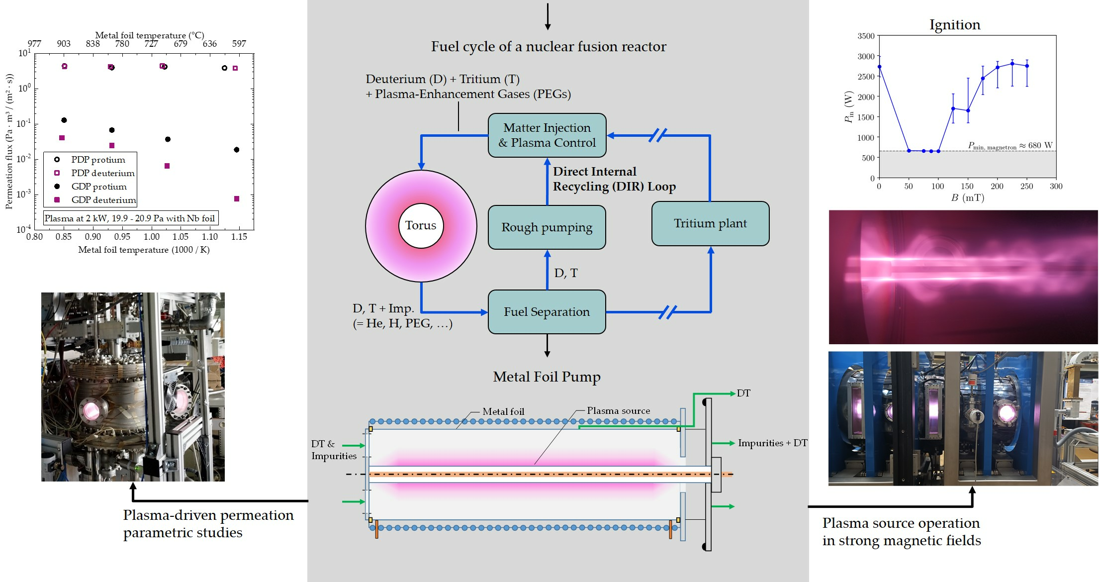
13]. Each module consists of a coaxial plasma source in the center and a surrounding, resistively heated metal foil with a thermal shield to the outside as is depicted in
Figure 1. The permeate, pure hydrogenic species (namely the fuel deuterium and tritium, DT, with small amounts of protium H as an impurity), is recycled directly to the DEMO matter injection systems while the retentate, the non-permeated hydrogenic species, helium ash, impurities and plasma enhancement gases (radiative seeding), is routed to the tritium plant. In principle, the permeation flux can be controlled via the microwave power input as is shown in the results. We aim to achieve a DIR-ratio of 0.8, which is the ratio of permeated hydrogen to hydrogen entering the pump [
2,
14].
2. Materials and Methods
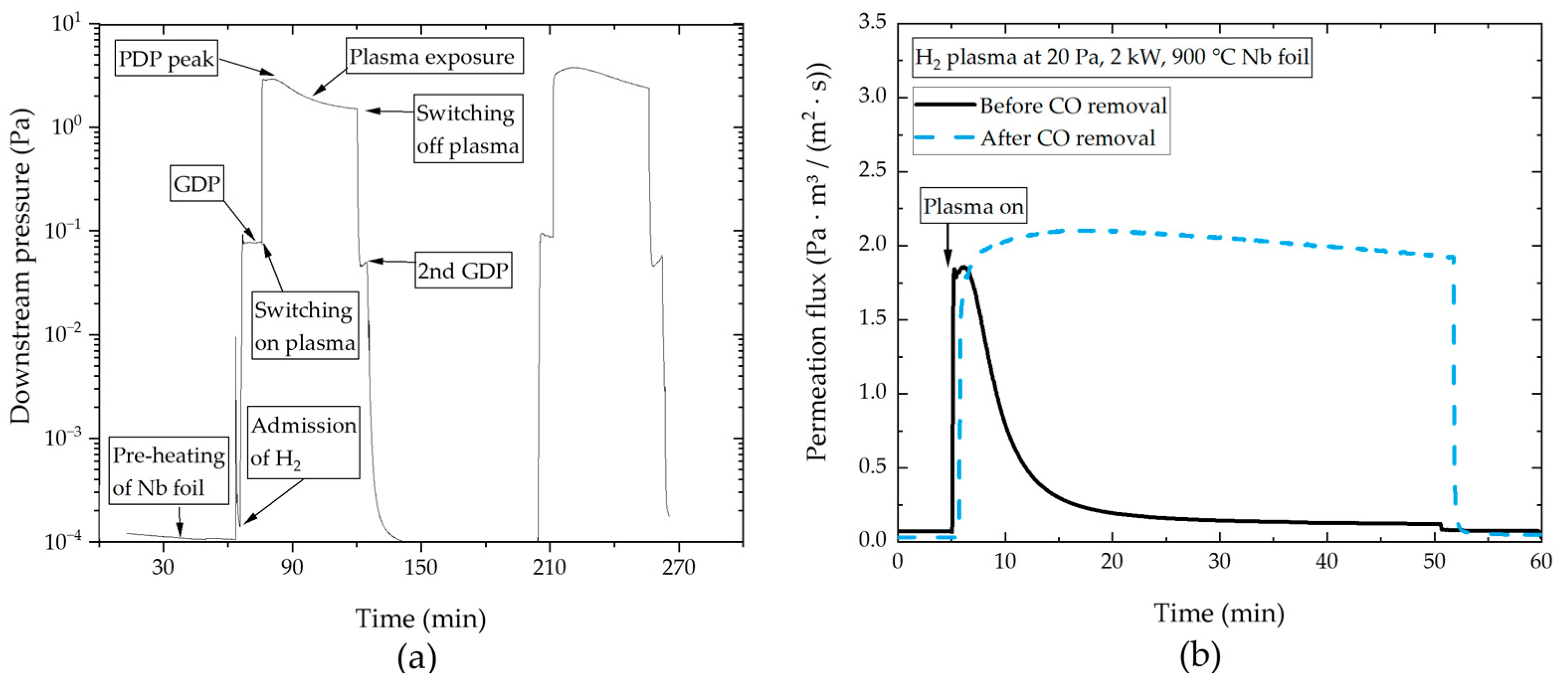
Plasma-driven permeation (PDP) has been observed and described in the literature before [
9,
15,
16]. Its characterization is based on a rather data-rich foundation when it comes to low pressures plasmas or hot metallic ribbon atomizers for the energization of hydrogen. However, to the authors’ current knowledge, there are no data available from other experimental work using higher-pressure (as high as up to 10–60 Pa in our application) RF plasmas as a source of suprathermal hydrogen. This is why we started with proof-of-principle experiments. Furthermore, parametric studies are required to determine the behavior and magnitude of PDP with varying pressures, plasma power and metal foil temperatures.
The experimental temperature range was chosen to be high enough to avoid damage to the foil caused by hydride formation and hydrogen embrittlement, and to reduce the hydrogen solubility (and thus the inventory) [
17]. For temperatures lower than those shown, PDP fluxes decreased as the monolayer turned into an oxide. We expect that the requirements on the operation conditions in terms of sputtering yield and purity of the foil make it too challenging to sustain high PDP fluxes below 500 °C. Moreover, operation at higher temperatures improves the segregation of O to the surface, increasing sputter resistance. Finally, the heating by the chosen plasma source itself is already sufficient to make the membrane reach temperatures above 500 °C, which makes operation at this temperature range more energy-efficient than adding additional cooling necessary to establish low-temperature operation. Based on these aspects, we do not focus on low-temperature operation in this paper.
We first present performance results for the two hydrogen isotopes, protium and deuterium. In the torus exhaust, xenon, helium and argon will constitute notable impurity gases, which dilute the hydrogen gas in the MFP. Along the MFP axis, their molar fraction in the gas increases while hydrogen permeates through the foil. We investigate the effect of noble gas presence in the hydrogen plasma qualitatively via the evaluation of the relative change in PDP fluxes while seeding the plasma with Argon.
In [
6], we introduce the central role of our experimental setup, HERMES
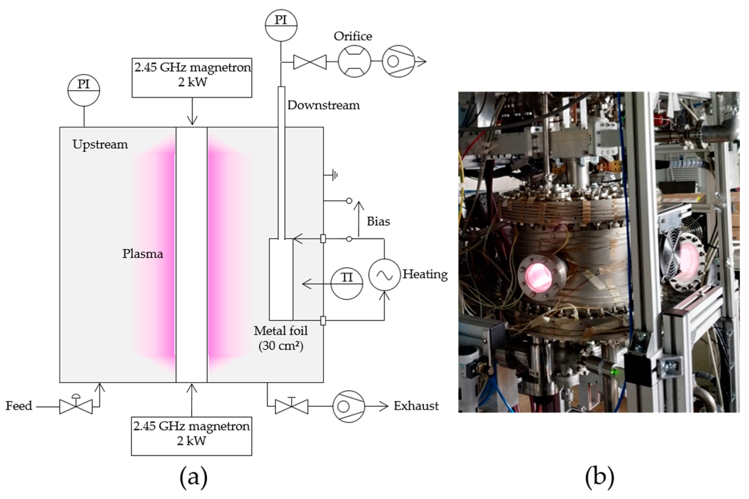
plus, illustrated in
Figure 2a,b, in the development of a MFP. It is equipped with a linearly extended surface wave sustained microwave plasma source at the center [
10,
11,
18] and a 0.1 mm thin cylindrical 30 cm
2 metal foil at a ~100 mm distance from the plasma source. In rectangular waveguides, a microwave of 2.45 GHz, produced by two magnetrons, is delivered to a coaxial line at the center of the plasma vessel. The inner conductor made from copper is surrounded by a dielectric tube. It is transmissive to microwaves, thus allowing the microwaves to enter the vacuum, where plasma can be ignited. This design of plasma source exhibits good scalability. HERMES
plus is able to accommodate foils of different materials for comparison. A gas flow (H, D or Ar) can be admitted via calibrated mass flow controllers. The upstream chamber is continuously evacuated by a DN 100 TPU 180 H turbomolecular pump produced by
Pfeiffer in Asslar, Germany and two Ecodry 25 plus roots pumps produced by
Leybold in Cologne, Germany. The pumping of hydrogen can also occur through the metal foil and the downstream pump duct. The upstream pressure is continuously monitored by hot and cold cathode gauges in the low pressure regime and by two capacitance manometers (133 Pa and 1333 Pa upper range) in the operational pressure regime (~20 Pa). For the presented results, we use measurements of the capacitance manometer CM 1 by
Leybold (Cologne, Germany), which is consistently in reasonable agreement with a
MKS Instruments (Andover, MA, USA) 690A Baratron. With a continuous feed in operation, we regulate the pressure via a hand valve, which restricts upstream pumping. We control the metal foil temperature by manually adjusting the power input for resistive heating. The foil can also be electrically biased against the grounded vessel using the resistive heating current leads and an external power supply. The metal foil temperature is measured using a METIS M322 two-color pyrometer (500–1800 °C) produced by Sensortherm (Steinbach, Germany), which targets the bottom of the foil through a quartz window from the top of the downstream channel. The temperature variation along the axis of the foil is experimentally probed by pointing the pyrometer at the foil through one of the main vessel windows. Observed temperature differences along the foil axis are found to reduce towards lower foil temperatures. The measured difference is ~5 K at 900 °C, which is in the order of magnitude of the pyrometer’s measurement uncertainty.
The downstream chamber starts at the rear side of the foil and ends at the inlet of the downstream turbomolecular pump, a DN63 HiPace80 produced by
Pfeiffer (Asslar, Germany). To run compression experiments, we can close off the downstream chamber with a gate valve. In regular permeation experiments, the downstream chamber is evacuated through a precision-drilled orifice of 4.3 mm diameter and 2.1 mm length. A permeation flow is obtained via the multiplication of the downstream pressure by the effective pumping speed of the system,
Seff, which is constituted by the pumping speed of the turbomolecular pump for the respective gas species (H or D),
Sp,i, and the conductance through the orifice, according to
where
dori is the orifice’s diameter,
R is the universal gas constant,
Td is the downstream temperature and
Mi is the mass of the gas species. Through knowledge of the orifice’s dimensions, the gas species and the downstream pressure, the flow regime at the inlet of the orifice can be determined, to read a transmission probability,
η, for the orifice from from [
19] and Figure 8 therein. The downstream pressure is measured via a hot cathode gauge (A micro-ion transducer of the 355 series produced by
MKS Instruments in Andover, USA) at low pressures and via three Baratron capacitance manometers (type 690A by
MKS Instruments, Andover, MA, USA) at higher pressures. A gas correction factor for the measurement of the hot cathode is introduced, which puts it in line with the Baratron measurements above 1 Pa, both of which are in reasonable agreement within their individual uncertainty bars. During all experiments, the laboratory is air-conditioned, which accounts for a steady downstream chamber temperature.
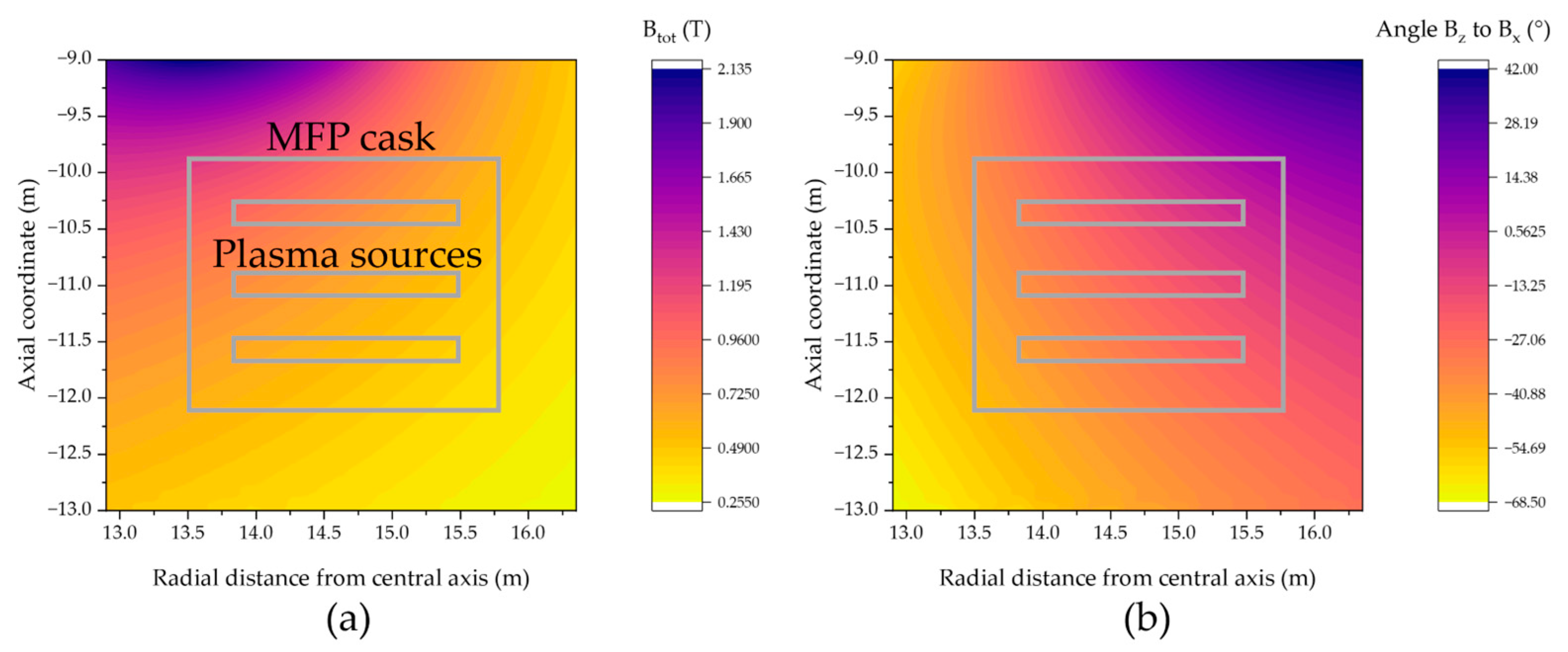
In the DEMO pump duct, the MFP is subjected to a strong external magnetic field during operation. The total magnetic flux density is composed of the radial, the axial and the toroidal field component. While the first two are relatively high in value and gradient, the last is negligible in the volume not encompassed by the toroidal field coils. In the pump duct space, the absolute magnetic flux density reaches values of up to 1.2 T, radially and axially decreasing to 0.3 T, as shown in
Figure 3a. The angle between B
z and B
x is displayed for the MFP location in ° in
Figure 3b. Depending on the magnitude, gradient and orientation of the magnetic field, we expect that this magnetic field affects the operation of the MFP plasma. The ratio of the gyro-frequency to the collision frequency, also called the Hall parameter, is an easily obtained parameter for a first assessment of the severity of the magnetization of the plasma. We calculate this ratio to be 15,100 for electrons and 1.95 for D
2+ ions in the MFP, corresponding to the largest given magnetic flux density (1.2 T) and the lowest pressure (1 Pa) in the MFP. For details and basic assumptions of the procedure behind such a calculation, the reader is referred to [
20]. Hence, we can consider the electrons to be well magnetized over the entire range of the magnetic flux density in the pump cask and the pressure range during operation, giving rise to distortions due to anisotropic charge mobility. Under the assumed conditions, ions are only marginally magnetized. The description of particle movement in such a non-thermal, weakly ionized magnetized plasma is quite complicated and modeling is challenging and computationally expensive. This is especially true when we superimpose a gas flow, strong field gradients and differentiate for each MFP module position inside of the MFP cask. A contemplation of all those aspects would be unfeasible and not provide the desired certainty, which is why we relegate it to a dedicated experiment, which is to take place in the future. We note that, due to the complexity of the described problem, experimental investigation is of paramount importance to back any conclusion drawn from simulations.
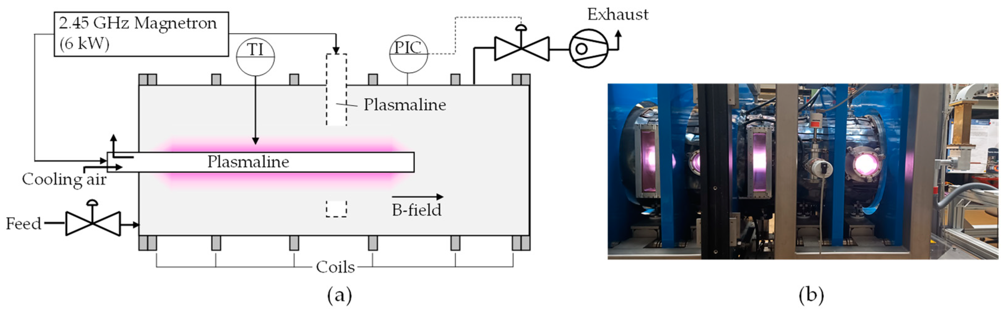
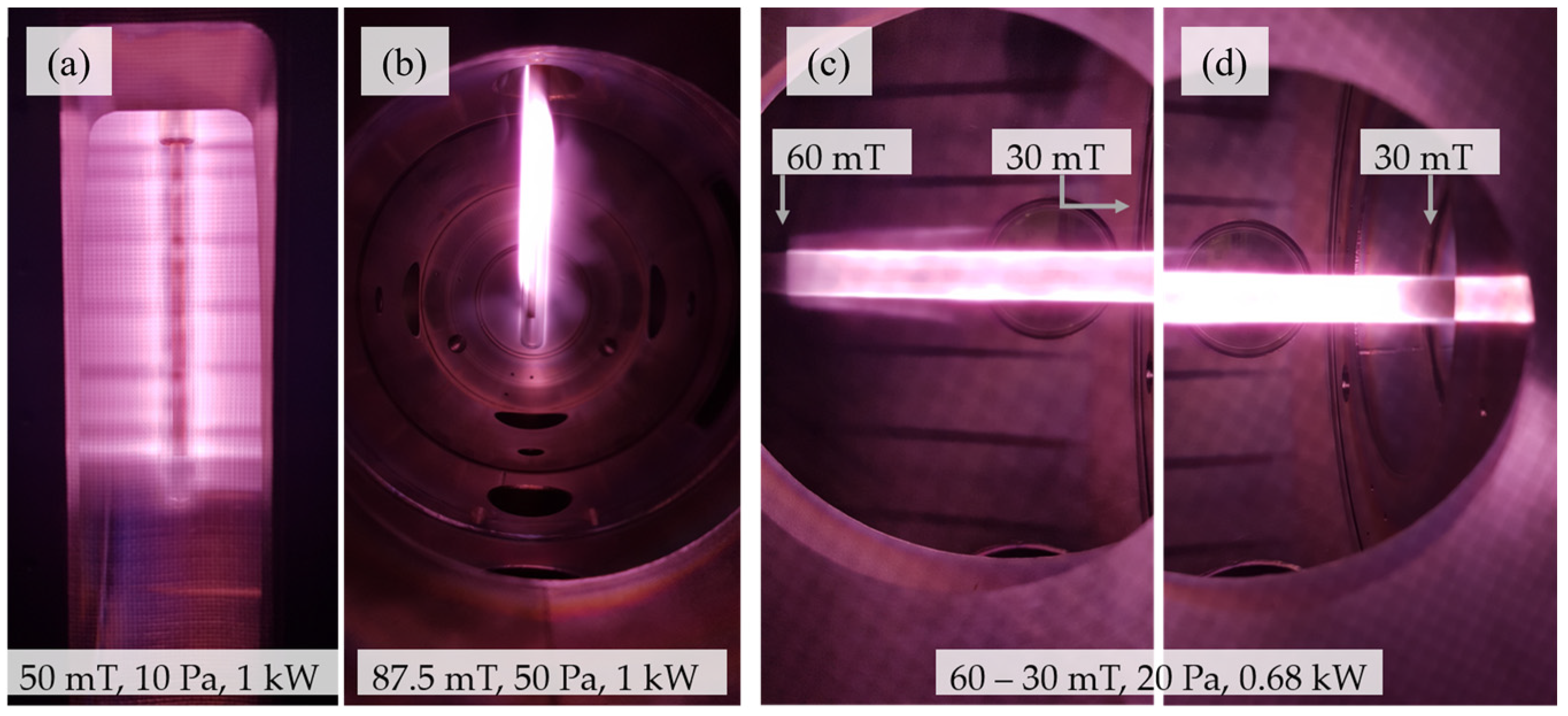
In a first approach to investigate the operation of the plasma source in a magnetic field, we use an available experimental setup, which allows for the production of operational aspects close to those in the environment in DEMO. Our investigation incorporates the assessment of the ignitability of the Plasmaline in a magnetic field, parametric studies of changes in flux density, pressure and power input and an analysis of the heat load on the plasma source itself. The FLIPS (Flexible Linear Plasma experiment Stuttgart) setup consists of a single-feed coaxial Plasmaline of 0.6 m length (up to 6 kW at 2.45 GHz) in the center of a cylindrical vacuum vessel, which is of 1170 mm length and 510 mm diameter. Along its axis, eight water-cooled copper coils are installed to produce a purely axial magnetic field. We measured the magnetic flux density with two Hall probes (A Koshava 5 probe, produced by Wuntronic in Munich, Germany and a Gaussmeter Model 425 produced by Lakeshore Cryotronics Inc. in Westerville, OH, USA) to be a homogeneous 250 mT inside the whole vessel.
The vessel features several windows and flanges for the installation of diagnostics. Those consist of optical emission spectroscopy (Compact spectrometer Jaz from
Ocean Optics in Ostfildern, Germany) for the analysis of the characteristic plasma emission, infrared camera (885 model produced by
Testo in Titisee-Neustadt, Germany) in front of an IR-transparent KBr window for the analysis of the plasma source dielectric tube’s temperature and optical cameras for the evaluation of the changes in plasma shape and ignitability with magnetic field. As shown in
Figure 4a, we can install the Plasmaline in two orientations: parallel and perpendicular to the magnetic field. The two coils at the end of the vessel can be powered separately to achieve gradient fields along the axis of the cylindrical vessel. Both protium and deuterium can be admitted to the chamber using 1179 model mass flow controllers from
MKS Instruments, Andover, USA. In all of the experiments, we feed up to 200 sccm of hydrogen and control the pressure with a 612 series butterfly valve (made by
VAT group AG in Haag, Switzerland) in the exhaust pipe. Downstream the valve, an ATP 400 turbomolecular pump by
Alcatel (produced in Annecy, France) and a vacuum rotary vane pump (made by
Pfeiffer in Asslar, Germany) are installed. The pressure is measured using an ASD 1004 gauge made by
Alcatel (Annecy, France) and a Vacuum CMR 363 gauge produced by
Pfeiffer (Asslar, Germany) for the low pressures up to 1 and 11 mbar, respectively, and a Vacuum PKR 251 gauge produced by
Pfeiffer (Asslar, Germany) for the full range.
Figure 4b shows an image of the facility.
4. Discussion
As shown in the presented experimental data, permeation fluxes as high as 6.7 Pa∙m
3/(m
2∙s) have been obtained. Most PDP experiments—also in other studies not included in this paper—have been carried out in a standardized operation scheme with a power input of 2 kW at a pressure of 20 Pa and a metal foil temperature of 900 °C. In these experiments, we consistently achieved permeation fluxes of at least 4 Pa∙m
3/(m
2∙s) for both H
2 and D
2, reducing down to ~1.5 Pa∙m
3/(m
2∙s) until a steady state was reached. Considering this performance and a desired DIR-ratio of 0.8, one can roughly derive a first estimate of the required foil surface area in DEMO. The current range of throughput foreseen for DEMO is 265–430 Pa∙m
3/s, coming from different contributions (unburnt DT, He, plasma enhancement gases, etc.) [
14]. Assuming that 95% of these are hydrogenic species, the removal of 80% of such species would yield a to-be-permeated flow of 200–327 Pa∙m
3/s. A simplistic scale-up from the HERMES
plus fluxes would yield a required membrane surface area of 50–82 m
2 for the case of observed PDP peak fluxes or 133–219 m
2 for achieved steady-state fluxes. Even though the latter range is clearly seen as a very conservative limit since the geometry of the setup is far from optimized for pumping and higher performances are to be expected in a real MFP, this surface need is very well in line with the current preliminary integrated design of a number of tubular MFPs (see
Figure 1) in a pump duct providing 19 m
2 pumping metal foil surface per duct [
13], as it corresponds to the need for 11 out of 16 available ducts for pumping in DEMO.
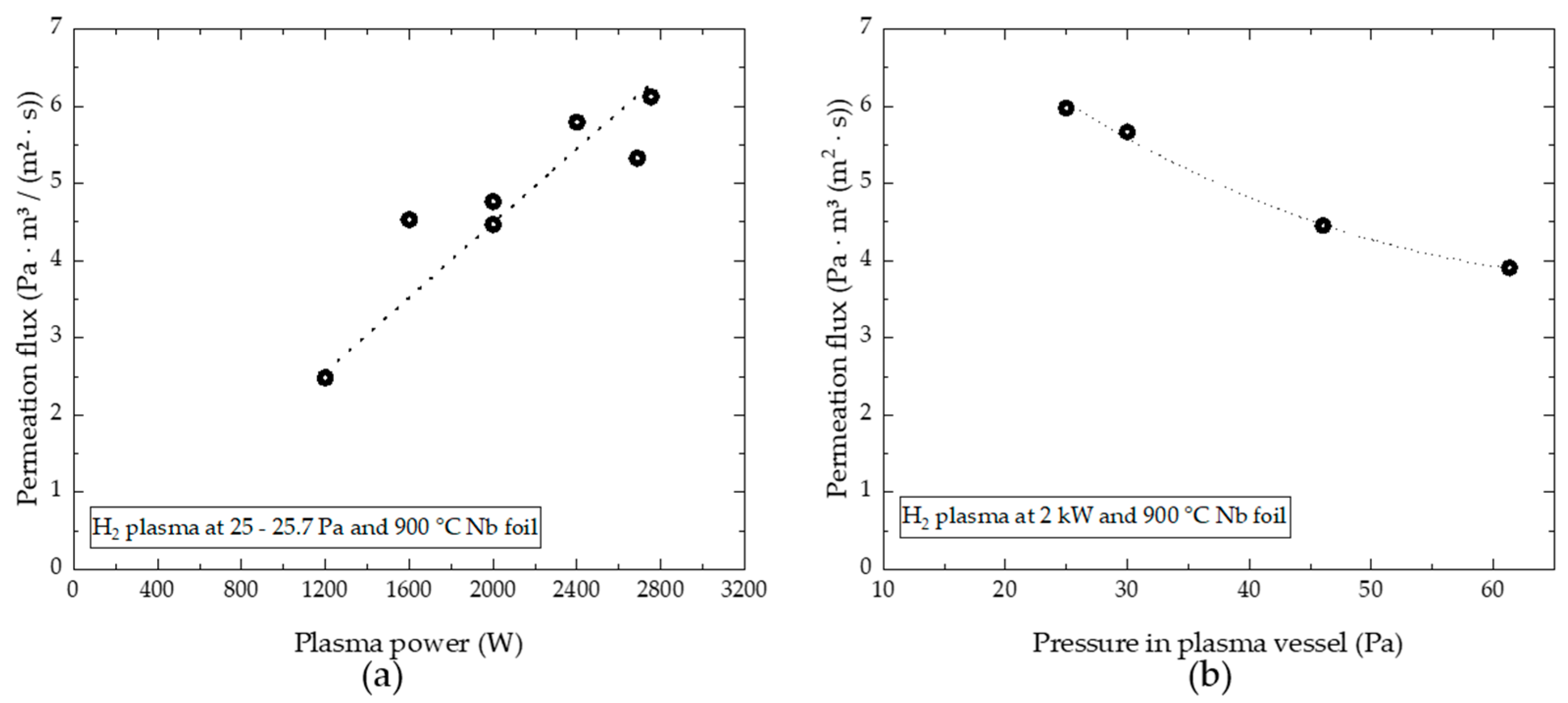
The permeation flux increases linearly with power until the power absorbed by the plasma saturates. Given the in-vessel plasma source length of 0.3 m with small extensions of a few cm over the outer conductor at each end in HERMESplus and a saturation power of 2.8 kW, we can approximate that for this type of Plasmaline, a power of about 8 kW per m can be coupled into hydrogen plasma at 20 Pa. We note that pressure and plasma source diameter affect this value, hence it should only be considered a first approximation for the design of the microwave power distribution system for the MFP modules in DEMO. Furthermore, the magnetic field can impact energy coupling into the plasma strongly, as will be explained more thoroughly below.
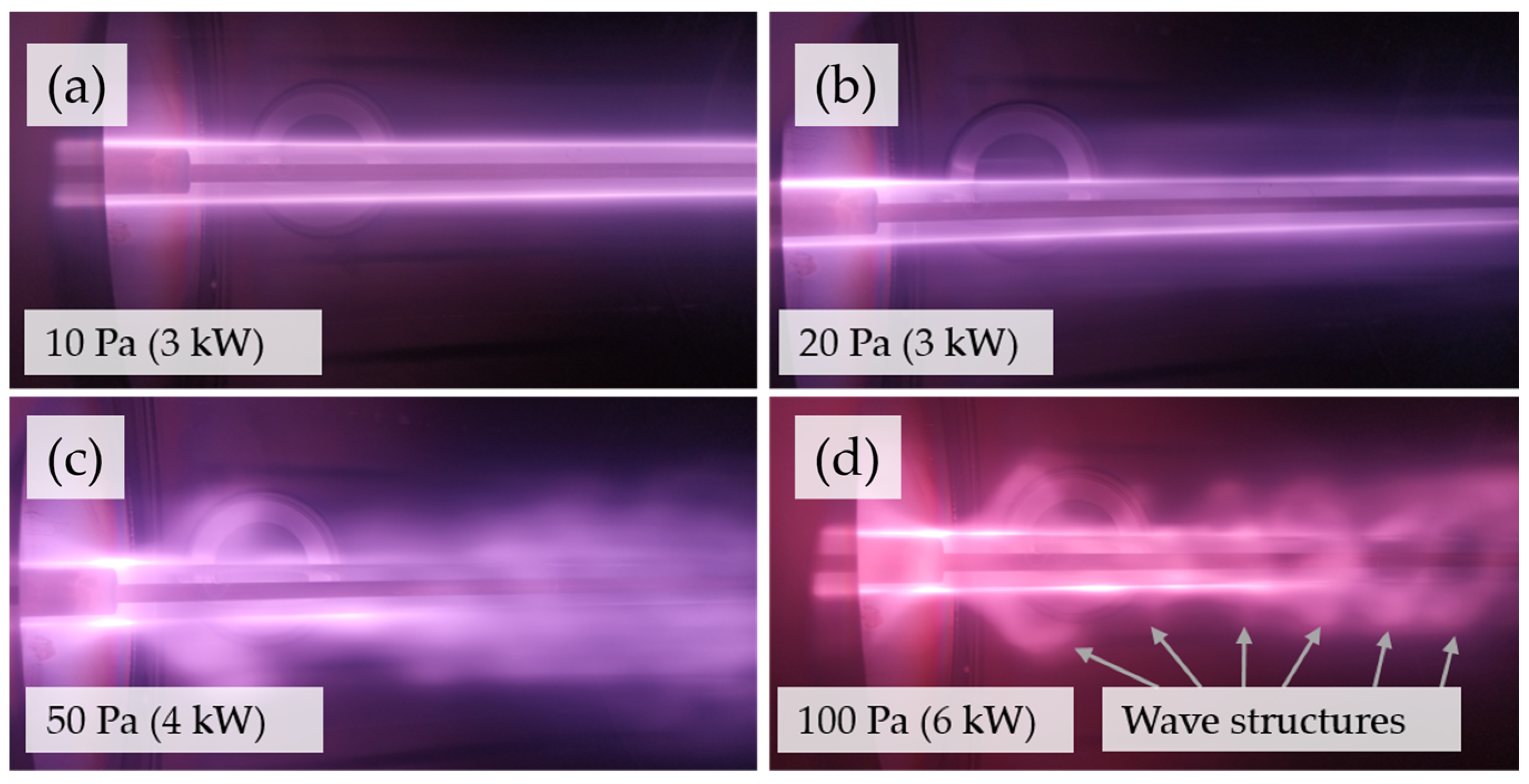
As with increasing power, permeation also increases with decreasing pressure due to increased production of suprathermal hydrogen. For hydrogen plasma, there is a lower pressure limit of plasma source ignition at ~10 Pa. However, the operational range can be significantly extended to a lower pressure via the admission of noble gases such as Ar with typically high electron densities or via the superposition of magnetic fields, as is the case in the DEMO pump duct. It is not entirely clear yet which permeation fluxes can be reached in a magnetically assisted discharge at even lower pressures around 1–5 Pa—a possible pressure range if the divertor is not operated under high neutral density. Typically, magnetically assisted microwave discharges are most stable and electron temperatures are the highest when the electron-cyclotron-resonance (ECR) condition is reached. For the given 2.45 GHz microwave, this is the case at 87.5 mT. In DEMO, as pointed out in
Section 2, the flux densities are one order of magnitude larger.
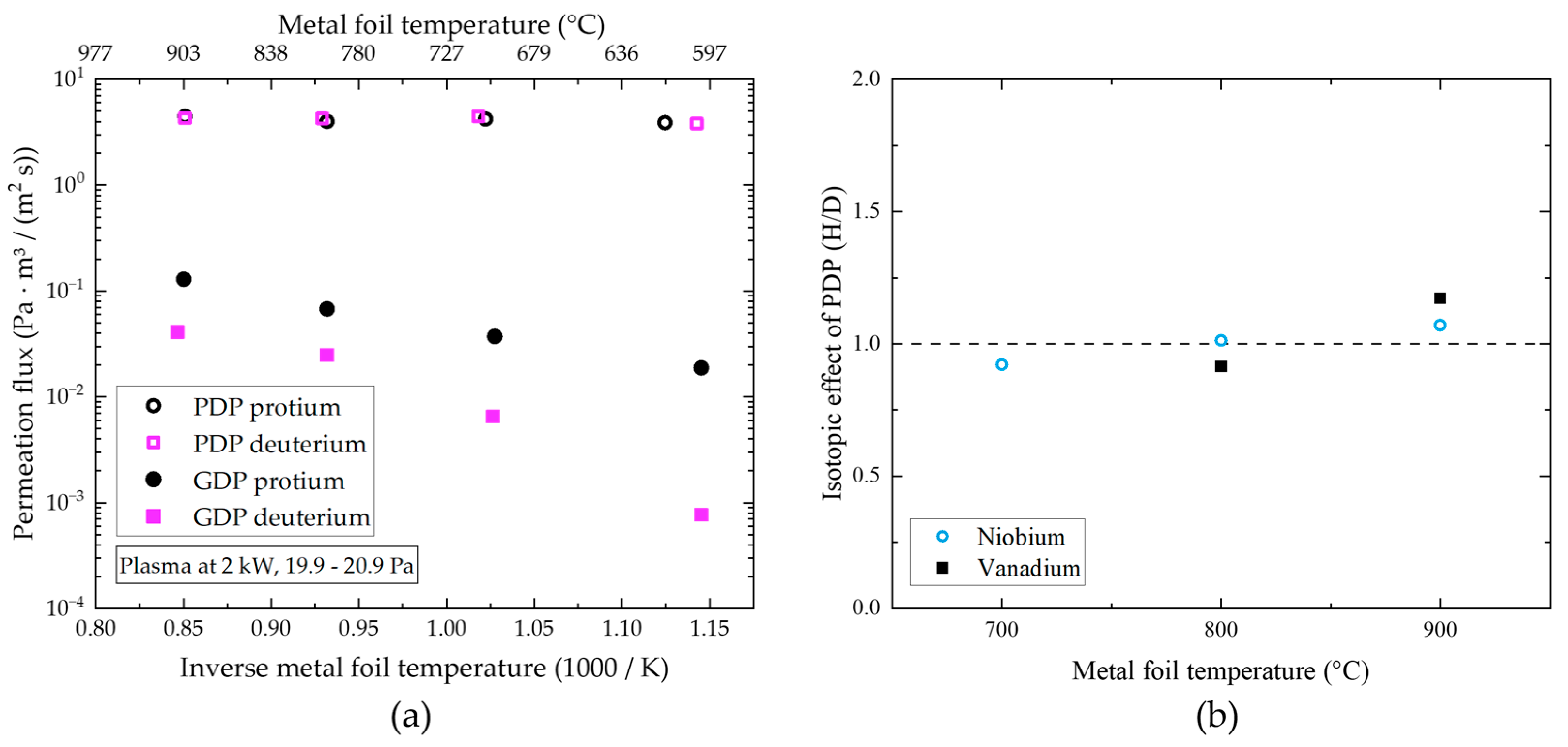
The independence of the permeation flux of hydrogen on temperature and on the isotope is a very promising result considering no additional recycling or isotope rebalancing is necessary before routing to the matter injection systems. While for Nb, the theoretical value for the maximum achievable permeation flux with plasma decreases with temperature [
17], experiments usually show that the achievable flux (below the theoretical limit) still increases with temperature in our setup due to the better preservation of the oxygen monolayer on the surface. For technological applications, the lower temperature range is more attractive owing to lifetime, energy efficiency and mechanical stiffness. Nevertheless, there are several shortcomings of the operation of group 5 metals at low temperatures, such as the observed reduction in oxygen surface segregation [
8], or the increase in hydrogen embrittlement [
17]. Recently, other groups [
21] have shown interesting results with Pd-based flat membranes and inductively coupled RF plasma at low temperatures (75–200 °C). The permeation values are remarkably high, but the scalability towards fusion conditions remains unclear.
The found compression ratios of the order of 10 or more are in line with what is needed to feed a continuously working mercury-vapor-based booster ejector pump, so that in the pumping path of the permeated gas, no diffusion pumps are necessary. This is a very important confirmation of the vacuum pumping train reference concept.
The findings of plasma source ignitability in a magnetic field also require a critical discussion in view of a MFP operation in DEMO. First of all, we point out that the main species responsible for superpermeation in our plasma is neutral atomic hydrogen, which is not affected by the magnetic field itself. Furthermore, drag effects from ion movement can be neglected due to the low degree of ionization [
10]. Hence, permeation flows can only be negatively affected by the magnetic field if (a) the plasma does not ignite or absorb the microwave power, (b) the plasma shape is distorted so much that it extends out of the MFP or (c) the electron energy distribution function (EEDF) changes to the disadvantage of hydrogen dissociation. With the presented experiments, we want to address cases (a) and (b), while case (c) requires sophisticated modeling of the exact DEMO magnetic field in the pump duct, which is not feasible to conduct at the current design stage.
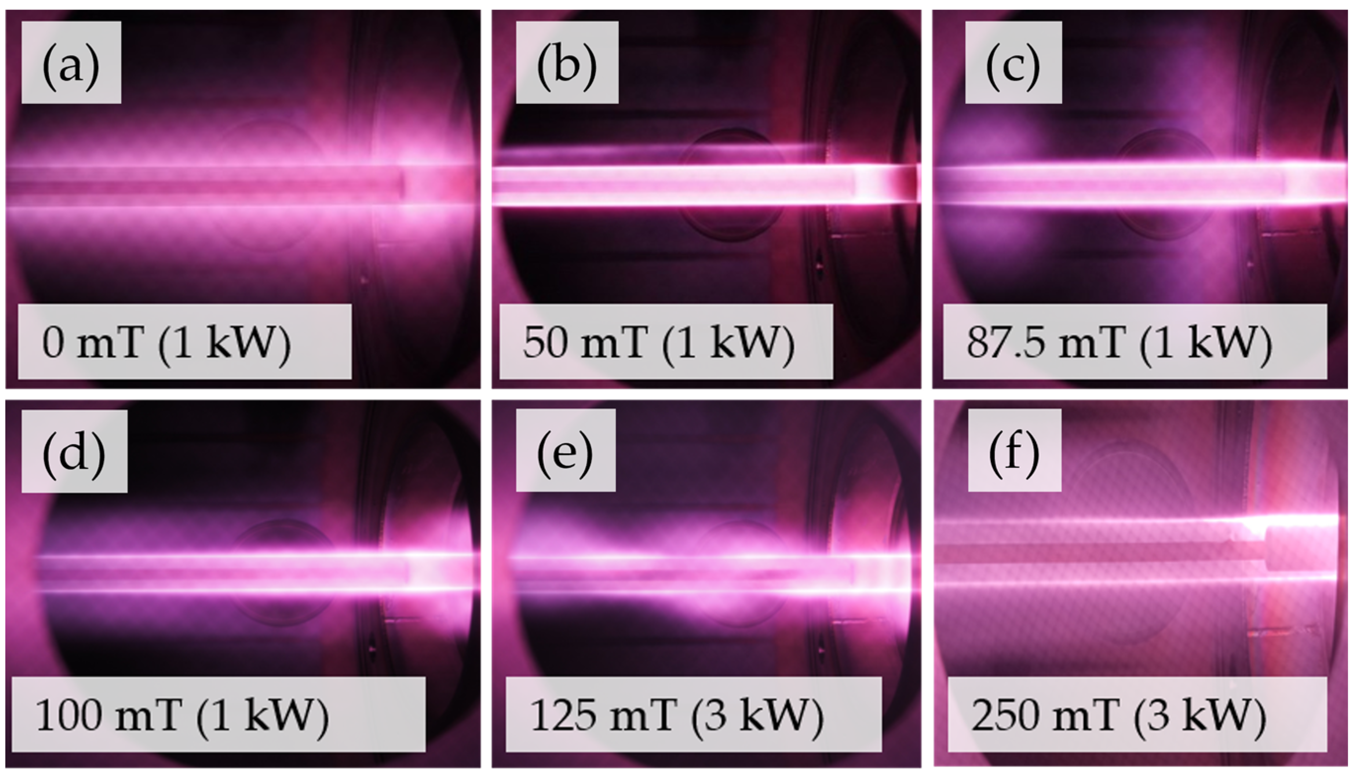
For a parallel magnetic field, a general observation is that an increase in pressure promotes cross-field movement of the charges that opposes the constriction of the plasma usually observed with pressure. For the pressure range of interest, this effect is small as the electron gyro-frequency is still orders of magnitude larger than the collision-frequency. The length of the plasma extends significantly in the direction of the magnetic field in some configurations. We achieved plasma extension beyond the end of the Plasmaline by reducing the pressure to below 5 Pa or combining high power input and high magnetic flux densities. We explain this via the associated increase in the mean free path, which allows the particles to travel further before recombining and via the strong magnetization of the plasma with severely reduced charge losses in the radial direction. Thus, we want to emphasize that for our application, pressure and power input have a major effect on the plasma shape. Considering the magnetic field for the current fusion plasma scenario, we cannot make a definite statement on the shape and volume of the plasma or if this puts a requirement on the geometry of the MFP modules. However, we gained valuable insights into the ignitability of the plasma, which depends on the angle between electric and magnetic field and the electrons’ mobility in electric field direction.
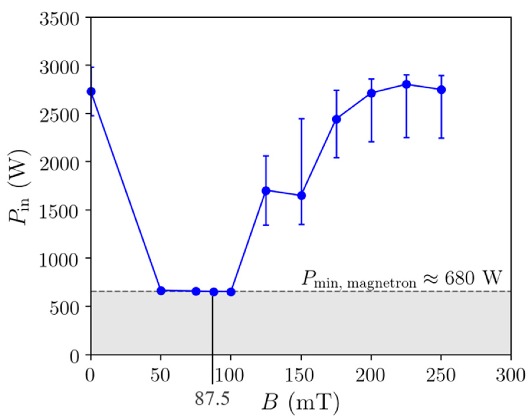
Figure 15 presents the experimental findings as required power for plasma ignition over magnetic flux density in the parallel setup with 10 Pa pressure. The lowest magnetron power input possible was 680 W. During the experiments, we observed some variations in the required power inputs and in microwave reflection, which was probably caused by a change in the impedance of the system for different operation conditions. We see that plasma could be ignited with minimum power around the ECR field strength. When increasing the magnetic flux density, more power was required. The important transport properties, conductivity and diffusivity of electrons are complex functions of the magnetic field and depend on its direction. Hence, the extrapolation of the measurement data via a fit function of any shape is not applicable to the prediction of accurate required microwave powers to ignite the plasma at even higher magnetic flux densities.
To be more realistic, we will, in the following part, derive a better way of extrapolation by means of a self-consistent 2D axisymmetric hydrogen plasma simulation in COMSOL Multiphysics with a parallel configuration of the plasma source and a homogeneous magnetic field. The plasma simulation uses a fluid approximation to describe the electrons with macroscopic quantities [
22]. The wave equation is solved for in the plasma domain, where resistive heating of the electron fluid succeeds based on the induced current, which can be defined through the plasma’s conductivity. The applied plasma chemistry determines the power transfer from the electron fluid to the heavy species. The simulation results, still, have to be considered a rough approximation, as a homogeneous B field leads to a different behavior from that of an inhomogeneous one at the same magnitude, as the FLIPS experiments showed with ignition at low pressure with inhomogeneous magnetic field.
Introducing an axial, homogeneous, one-directional magnetic field into the 2D plasma simulation allows us to draw some comparisons to the experiments. We consider the magnetic field in the tensors for mobility and diffusivity in the charge transport equations and in electron conductivity, which affects microwave propagation and wave heating [
22]. The resistive heating term of the electrons is given by
where
is the electron current density,
E is the microwave electric field and
σ is the electron conductivity. Without magnetic field, the electron conductivity,
σ, is a scalar and resistive heating is determined via the current drive along the electric field. Since the radial component,
Er, of the electric field is the strongest for the coaxial waveguide, it has the highest contribution to heating [
11]. The
Ez component has a minor contribution and
Eφ in azimuthal direction is zero without magnetic field. With presence of a magnetic field, the conductivity has to be described as a tensor. With a one-directional magnetic field parallel to the Plasmaline, it becomes
where
σ0 is the plasma conductivity without superimposed magnetic field. The induced currents are then given by
The conductivity,
σzz, and the current,
Jz, are parallel to
B and
Ez and remain unaffected by the magnetic field. The diagonal elements
σrr and
σφφ are also called Pedersen conductivity and are perpendicular to
B but parallel to the respective component of the electric field. The off-diagonal elements (Hall current) are caused by the ExB drift and are perpendicular to
B and
E. In contrast to the case without magnetic field, a current is, therefore, also induced in
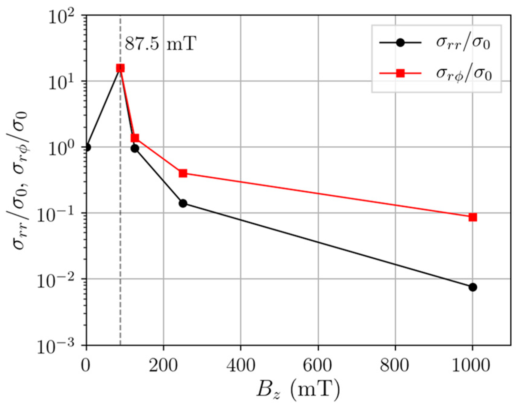
φ-direction and there also exists an azimuthal electric field. For magnetic fields beyond the ECR field strength, the perpendicular conductivities
σrr and
σφφ exhibit the largest decrease. In
Figure 16, we present simulation results for the ratios of parallel-to-perpendicular conductivities for hydrogen plasma at 20 Pa and 2 kW input power and their change with the magnetic field. We see that cross-field conductivity and, therefore, the plasma’s efficiency to absorb power of the radial electric component of the microwave declines quickly with B. When considering the single components, the resistive heating term can be written as
The Hall current terms cancel each other out because of
σrφ = −
σφr. If only the radial component is considered, then the scaling of the resistive heating term would be
, with
decreasing the most out of the three conductivities with
B (see
Figure 16). Thus, a reduction in
leads to the largest increase in required input power to obtain the same resistive heating in the plasma.
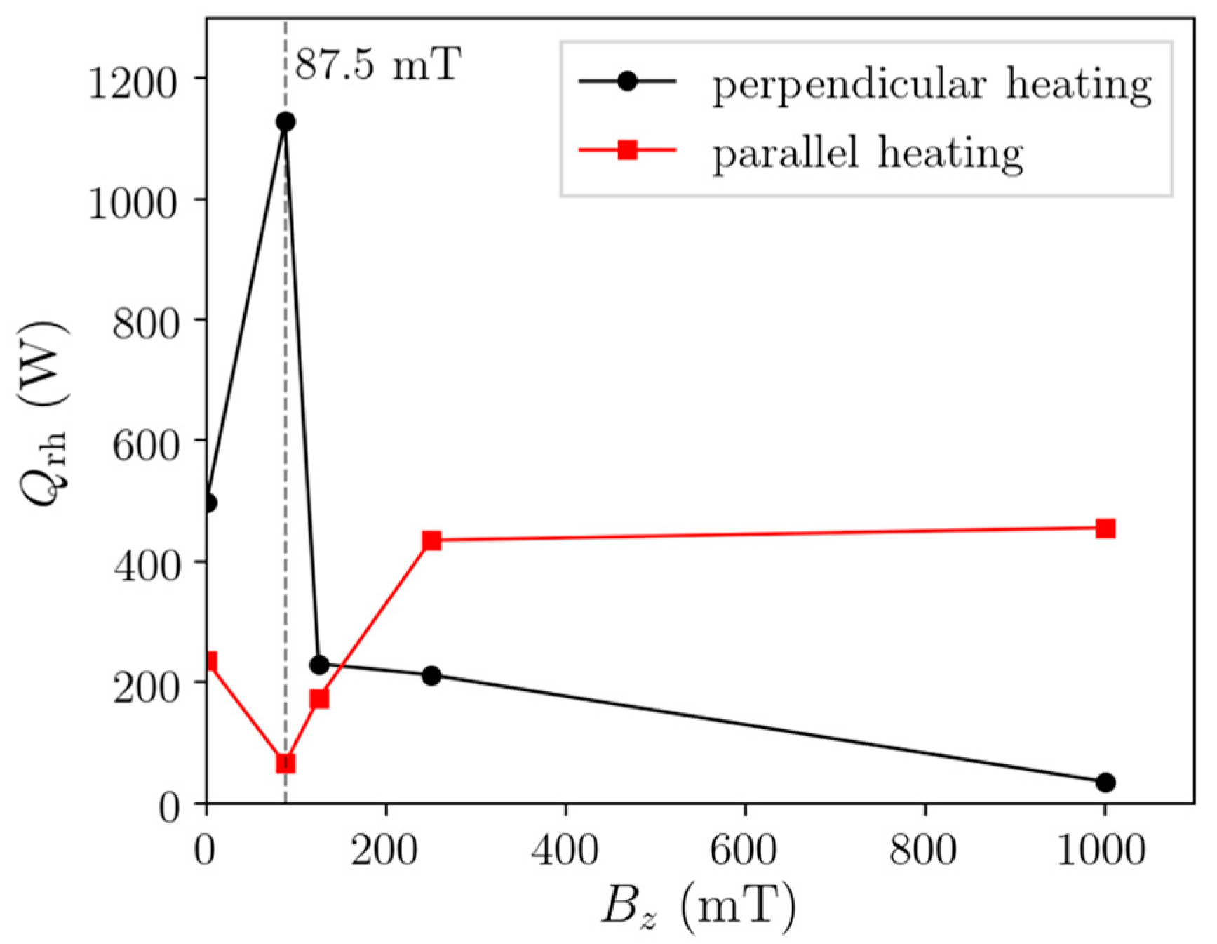
However, simulations show that a plasma can be built up at 1 T even with input powers around 2 kW. Also, the experiments do not show such an increase in required power up to 250 mT. In the simulation, we find the reason for this when looking at the directional contributions to the heating term individually. In
Figure 17, we present the total absorbed power with changing parallel magnetic field strength. Peaking at 87.5 mT, the power absorbed from the perpendicular electric field component declines rapidly for higher B fields. Instead, there is a transition taking place where the plasma is heated efficiently by the parallel electric field component, which allows the plasma to be maintained even at 1 T.
The parallel electric field component plays an important role at higher magnetic flux densities as the conductivity in the perpendicular direction decreases. The coupling of the axial wave component is probably also the reason why the required power for ignition in
Figure 15 only increases by 1 kW from 125 to 250 mT. As pointed out before, the curved, gradient three-dimensional
B-field in
DEMO complicates the situation and requires consideration in an extension of our current plasma simulation. However, here, we show the principal behavior of microwave power coupling and that improvements in ignition can be made by aligning electric and magnetic fields.
One would expect the parallel configuration in FLIPS to demonstrate a worst-case scenario in terms of plasma ignition as the electric field is always perpendicular to the magnetic field. Still, we found that at the highest magnetic field strength of 250 mT, ignition was always possible in this configuration if we increased the power sufficiently, which we interpret as a reassuring result.
5. Conclusions
In this work, we describe experimental results obtained in the HERMESplus setup at KIT and in the FLIPS setup at the University of Stuttgart. We report on the handling of undesired impurities and a related modification of the plasma source design. We were able to obtain high permeation fluxes of up to 6.7 Pam3/(m2s) and investigated their dependency on pressure and power input. Not only was the achievable flux sufficient, but also the achievable compression ratio of more than one order of magnitude provided a pressure that was sufficient to use continuously in working booster ejector pumps further downstream in the vacuum pumping train. However, we note that the impact of the magnetic field on the permeation fluxes remains to be quantified.
Using conservative performance estimates, about 11 of the 16 available DEMO ducts would be required. However, we emphasize that this value cannot be linearly scaled due to multiple variables, which affect operation like changes in the pressure, effects of the magnetic field, reduction of the actual foil surface area in an integrative design and yet to be reached steady-state operation with such high flux values.
We also demonstrated the limits for power absorption of hydrogen plasma in the given coaxial discharge at 20 Pa to be approximately 8 kW per m Plasmaline, which can be taken into consideration for the design of microwave power distribution to the MFP modules. For the temperature range between 600 and 900 °C, we observed no significant isotopic effect for the PDP of protium and deuterium. In the same temperature range, the measured peak fluxes were independent of the temperature, which is proof of superpermeation.
The next step in the characterization of the PDP process and the investigation of the employed plasma source is the exploration of operation at lower pressures. In the present work, we show that PDP fluxes increase towards lower pressures. However, to achieve plasma ignition at very low pressures down to 1 Pa, the discharge requires assistance in form of a magnetic field. Thus, the HERMESplus facility will receive a major upgrade to allow for the installation of two Helmholtz coils. The new facility will be able to operate the plasma with magnetic fields of up to 100 mT in the bulk of the plasma.
The PDP experiments revealed the strong potential influence of sputtering of the oxygen monolayer by energetic plasma particles. To eliminate this, some design measures can be taken, such as the installation of a screen of the membrane from the direct line of sight of the plasma and further investigation into the characteristics of sputter-resistant foils for PDP are required.
We demonstrate the operability of the coaxial microwave plasma source in strong, homogeneous, one-directional magnetic fields of up to 250 mT with strictly perpendicular or parallel mounted plasma source. No mentionable difference in ignitability between H2 and D2 could be found. Only low cooling power was required to keep the plasma source temperature at reasonable levels during operation and maximum temperatures even decreased with magnetic field strength. Being the particle with the largest contribution to PDP flows, atomic hydrogen is not affected by the magnetic field itself; however, its production rate and its source location might be. The magnetic field helped ignite plasma at pressures below 1 Pa due to the confinement of charged particles and strongly decreased loss terms to the walls. Around the ECR magnetic field strength of 87.5 mT, the ignition of plasma was always possible even with a minimum power input of 680 W. With increasing magnetic flux density, the power input required to ignite the plasma rose. The experimentally determined increase in required power for ignition with magnetic flux density did scale much less than expected. It appears that the heating by the axial electric field, which is parallel to the magnetic field in the investigated case, increases with B.
Our findings indicate that the microwave heating at high magnetic fields works mainly via the absorption of the electric field parallel to the magnetic field. Since the Plasmaline works like a coaxial waveguide, the strongest electric field is in radial direction. Depending on the installation direction in DEMO, the microwave electric field of the Plasmaline might not be parallel to the magnetic field, which can lead to a lower ignition and heating efficiency. Therefore, a way should be found to amplify the electric field component parallel to B. This can be done, for example, by aligning the MFP to the expected magnetic field lines. Another approach is the modification of the shape of the inner conductors, possibly by adding conducting structures (rings, spirals, etc.) to their surface. It is recommended to explore this possibility in the future with corresponding experiments.
We recommend experimental investigation of the ignitibility of the plasma source in a magnetic field more representative of DEMO, with a higher field strength, strong gradients and three spatial direction components

 ,
, 


