1. Introduction
Additive manufacturing (AM) enables the production of mechanical parts with complex geometries in various sectors, such as automotive, robotics, aeronautics, and aerospace. This technology enables the use of just the right material to fulfill the required functions. This saves weight and raw materials while minimizing the assembly of multiple parts. These advantages make it a very competitive alternative to other manufacturing processes when it comes to small/medium production runs. This is one of the reasons why additive technology is gaining ground in the industrial world, particularly in aerospace and aeronautics, with the aim of lightening aircraft and thus reducing the carbon footprint of flights. AM is currently developing exponentially, with a growth rate of around 20%/year [
1].
Fused deposition modeling (FDM) or fused filament fabrication (FFF) is a material extrusion (ME) 3D printing method for polymers and fiber-reinforced composites. This technology has been significantly growing especially in the aerospace, automobile, and medical industries. The main advantages of the FDM method are its reliability, low maintenance required, low investment cost, wide low-cost filament material availability, and cost-effectiveness, and it is highly customizable. However, it is limited to low-melting-point materials, and it is also a slow printing process. Single-screw extruders are usually used in mass-production applications where pure polymers are used as raw materials. There are also a few commercially available filaments with continuous fiber already impregnated to an extrudable thermoplastic. For more complex applications, where precision and better properties are needed, twin-screw extruders can be used for blending two or more materials. A high degree of dispersion between the polymer matrix and the filler materials can be obtained. However, printers have also been modified to be able to coextrude in a single nozzle the fibers and the thermoplastic filaments that are fed separately. Thermoplastics are the most used materials in FDM systems. Their main advantages are their low cost and melting point. From the literature, these materials’ tensile strength can range from 1.5 to 150 MPa [
2]. However, pure polymers do not present enough mechanical properties for structural applications. Due to the low strength of pure polymers, they can be either filled or reinforced to improve their mechanical properties. Acrylonitrile butadiene styrene (ABS), polylactide (PLA), and polyamide (PA) nylon are widely used as matrix materials. Their low melting point is the main reason for their vast applicability.
Other functions can also be sought in printed materials, such as electrical conductivity. Ryan et al. [
3] are particularly interested in the conductive functionality that can be achieved using the FDM process. The use of conductive filaments has a negative impact on mechanical properties. Conductive polymers are therefore also a limiting factor in development because of the poor mechanical properties obtained. The authors recommend the use of a second polymer to obtain good mechanical properties as well as decent conductivity [
3].
The composite can also be filled with particles or short fiberswhere the fibers are already impregnated on the polymer matrix. Short fibers can be twice as strong as pure plastic, and there are some commercially available filaments with impregnation that, normally, are filled with short carbon fibers. On the other hand, continuous-fiber-reinforced composites can be 30 times as strong as pure plastic [
4].
Short-fiber reinforcements provide better tensile modulus than unreinforced, but the tensile strength is not improved. Continuous filament reinforcement composite polymers (CFCRPs) offer superior properties and are normally fabricated by expensive methods [
4]. The FDM method allows printing CFCRPs in complex geometries [
5,
6]. On the other hand, the specimens fabricated by this method present lower tensile strength than other methods, which is mostly because of the poor polymer–fiber adhesion [
6]. While the aerospace industry tolerates porosity rates under 1 vol%, the porosity of continuous-fiber-reinforced thermoplastic composites (CFRTPCs) is 5–10 vol% [
5].
The introduction of fiber into a matrix makes it possible to improve mechanical properties. The 3D-printed part can be given electrical properties to make it a multifunctional composite [
6].
In the case of multifunctional composite structures, the active material does not only fulfill its function as a load-bearing structure, but also performs additional functions. The fiber used in the polymer adds functions to the composite part [
7].
Introducing carbon fiber into 3D-printed parts also provides electrical properties. These electrical properties will also have an impact, enabling the part to obtain other functional properties, such as a sensor, for example. One of the main functions that can be conferred on the composite structure is self-sensing, which makes it possible to become aware of the state of the structure [
7] without the aid of an integrated or mounted device. The main principles of self-sensing are direct piezoelectricity, thermoelectricity, and piezoresistivity [
8].
Bekas et al. [
9] have established a literature review with a summary of the research efforts for the development and characterization of 3D-printed multifunction composites. In 3D printing, functionality mainly consists of loading the raw material with carbon nanotubes or black carbon to provide conductive or sensing properties [
9].
Kim et al. [
10] propose to print a sensor using the dual-nozzle fused deposition method (FDM): one with a commercial filament and another with a functional nanocomposite filament (carbon nanotubes (CNTs) and thermoplastic polyurethane (TPU)). The second nozzle enables the filled filament to be deposited directly on the workpiece, creating a functional sensor without assembly. These filaments can then be used to target the sensor zones of the printed part, enabling them to be connected to these parts. The sensor thus offers signal information in three directions, and the difference in resistivity can thus give an indication of the force exerted. Kim et al. [
10] mention that additive manufacturing anisotropy leads to a difference in recovered signals. It is possible to correlate the strain exerted by a difference in resistivity to thus obtain a sensor. A similar experiment was carried out with printed strain gauges, again using the electrical properties of a thermoplastic doped with carbon particles, taking into account the influence of temperature variations on the material’s resistance value [
11].
Gackowski et al. [
12] demonstrate multifunctional 3D printing for nylon with the addition of another piezoresistive material for structural health monitoring. The concept of 3D printing nylon structures with embedded piezoresistive sensors of carbon nanotubes and short carbon fibers is investigated. Modifications in electrical resistance can be detected in tensile, flexural, and indentation tests, up to and including material failure. The order of magnitude of the resistivity of the printed sensor corresponds to the order of semiconductor magnitude [
12].
Another alternative is using carbon fiber. Georgopoulou et al. [
13] propose to embed manually the filament in an elastomer to obtain a piezoresistive sensor. The elastomer is printed directly onto the carbon fiber to create a sensor that is assembled on the robot arm. This is then controlled using an Arduino to obtain the position of the robot arm. The electrical signal can then be analyzed to verify the position of the robot arm and match the signal of a human finger to that of a robot finger. This method shows that when the fiber is displaced longitudinally, it is possible to obtain an electrical signal that is repeatable and directly related to the imposed angle. Nevertheless, the operations required to obtain the sensor are complex and require an assembly step on the robotic arm [
13].
The additive process makes it easier to introduce carbon fibers into the part during the process. This has led to renewed interest in the correlation between electrical resistivity and deformation. Yao et al. [
14] evaluate the embedding of manually inserted carbon fiber during the manufacturing process. They show that a link exists between mechanical and electrical behavior. The elastic zone can be detected by the resistivity measured on the carbon fibers [
14]. When a defect appears in the composite, the electrical signal is disturbed, causing a change in the direction of the slope. In fact, a change in the direction of the slope makes it possible to detect the breakage of the first fiber in the part and is therefore an indicator of damage to the part [
15].
Yao et al. [
14] define the gauge factor (GF) as the ratio of the relative change in electrical resistance to the relative elongation:
where ∆
R the change in resistance,
R0 the initial resistance (in Ω), ∆
L the change in length, and
L0 (in m) is the initial length. The calculation of the GF in the elastic period shows a certain stability. In the case of the study of a carbon fiber (3K) with a 20% PLA filling, the GF over the elastic period is 0.59 ± 0.13 [
14].
This shows the interest in using continuous fiber to obtain mechanical properties while at the same time providing interesting electrical properties. FDM printing of continuous fibers is relatively recent. Kabir et al. [
16] mention that the first continuous-fiber composite FDM appeared in 2014 by Markforged. There are two nozzles in the printer: one for preimpregnated fiber filaments and the other for pure plastic filaments. The matrix used is nylon (PA), and the reinforcing fibers can be carbon, glass, and aramid. The two separate nozzles are assembled on the same printhead. A cutting mechanism is used on top of the printhead, and a feeding mechanism is used to push the fiber filament into the nozzle. In this technology, paths for continuous fiber are limited to predefined trajectories [
17].
Galos et al. [
18] study the electrical conductivity of a composite obtained by Markforged technology. They show that there is an impact on conductivity that can be measured, mainly due to the process, which causes breakage during passage through the nozzle for printers not using the coextrusion principle. Electrical conductivity is measured using silver paint applied to the ends of the sample. This paint is then brought into contact with a copper electrode. It is not possible to access the carbon fiber to connect directly to it. This highlights the fact that additive technology has a significant impact on this aspect. This technology is a hindrance to the manufacture of an intelligent part. In the context of the additive forming of a thermoplastic continuous-fiber composite, Galos et al. [
18] also show that thermal post-treatment is essential to improve mechanical properties.
Other technologies, such as Anisoprint, are entering the continuous-fiber FDM market. Luxembourg-based Anisoprint has developed a 3D printer that is based on the patented technology of the coextrusion of a continuous composite-reinforcing fiber with a thermoplastic polymer. The high-performance physicomechanical properties of the material are ensured by the high-volume fraction of reinforcing fibers in the material, good adhesion between binder and fibers, fiber straightness and continuity, and reliable impregnation [
19].
The Anisoprint print head consists of a coextrusion head. The composite extruder introduces a thermoplastic filament which is heated to its extrusion temperature to enable the fiber to be deposited along the desired path. A cutter is placed at the entrance to the heating element, enabling the fiber to be cut when the frame or another layer is changed.
In addition, Aura’s slicing software allows great flexibility by giving you control over each print head. Paths within the printed part can be made freely. Indeed, masks can be used with Aura Premium to carry out an additional model. This model is added to the work area to intersect with the base model and to change the internal structure with or without carbon fiber [
4].
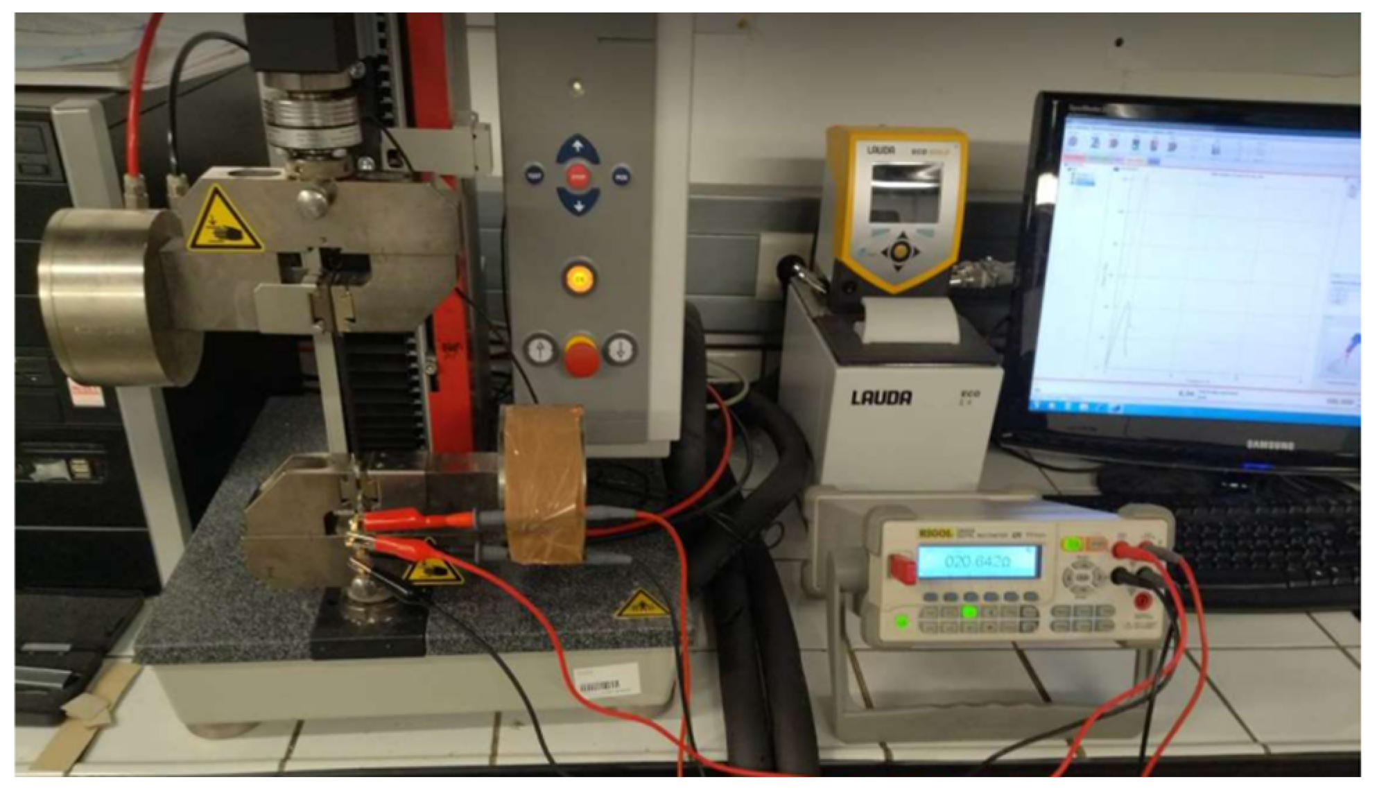
The aim of this paper is to use a continuous-fiber FDM printer to manufacture multifunctional 3D parts. To this end, FDM coextrusion technology is used to impart electrical properties through continuous carbon fiber, enabling a 3D sensor part to be manufactured without human intervention. This study shows the feasibility of embedding continuous carbon fiber along a defined path within a 3D part. The defined path is based on the characteristic paths observed in snaking strain gauges. This study also shows the impact of fiber introduction on both mechanical and resistive properties, and whether the resistive signal can be a reliable indicator to predict the failure of a 3D-printed part under load. This approach can be used for soft robotics to detect the gripping of a clamp or in structural health monitoring for autonomous drones to check the health of the landing gear before carrying out a new mission.
3. Results and Discussion
This section shows the results obtained during the tests, together with a discussion of the results. This section is divided into three parts:
- -
Without carbon fiber to see if the tests are repeatable
- -
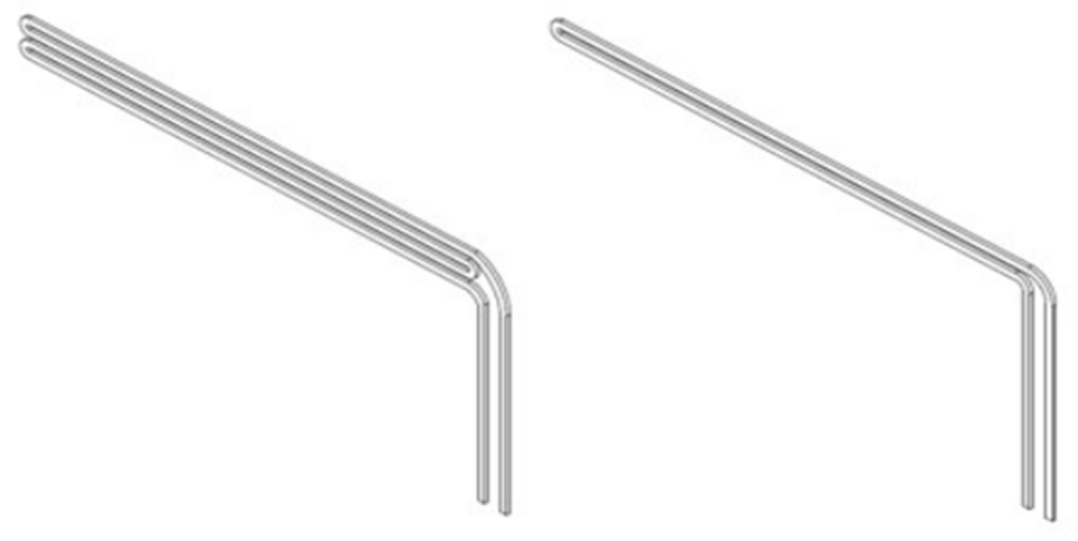
With W-shaped carbon fiber, which is the longest path in the printing plane and relates to at most one strain gauge
- -
With U- and W-shaped carbon fiber, and the addition of several layers of carbon to visualize trends.
3.1. Without Resistive Elements
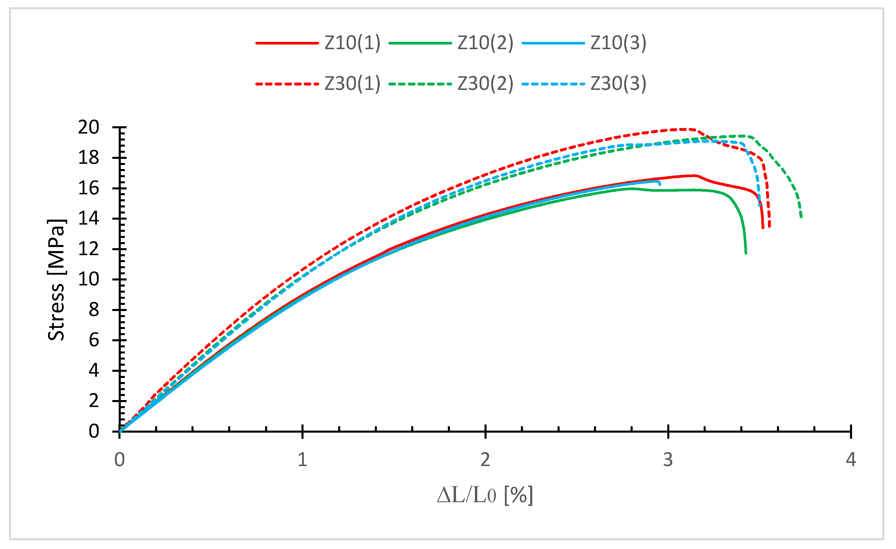
Figure 5 shows the tensile curves of the non-fiber series tests. It can be seen that each series offers a specific trajectory, and that the curves of the tests in the same series are similar to each other until failure.
It can also be seen that the mechanical properties are slightly improved by moving from a filling density of 10% to 30%.
At 10% (Z10), the average Rm is 16.42 MPa with a standard deviation of 0.35 Mpa and a Young’s modulus of 0.96 Gpa.
At 30% (Z30), the average Rm is 19.42 MPa with a standard deviation of 0.32 MPa and a Young’s modulus of 1.15 GPa.
Mechanical properties follow the trends expected for 3D-printed parts. Basic samples without carbon fiber continue to show a repeatable evolution with a Young’s modulus of 0.96 GPa and an Rm of 16.42 MPa for a 10% internal fill. The repeatable tests show that the chosen printing parameters are acceptable. Ali et al. [
21] show that increasing the filling of the PA structure increases the fracture stress in a rectilinear curve. As expected, when the material is added internally, mechanical properties are improved. Young’s modulus is similar for a series of specimens, but tensile strength varies slightly. This is mainly due to adhesion between the printed layers.
3.2. With W-Shaped Carbon Fiber
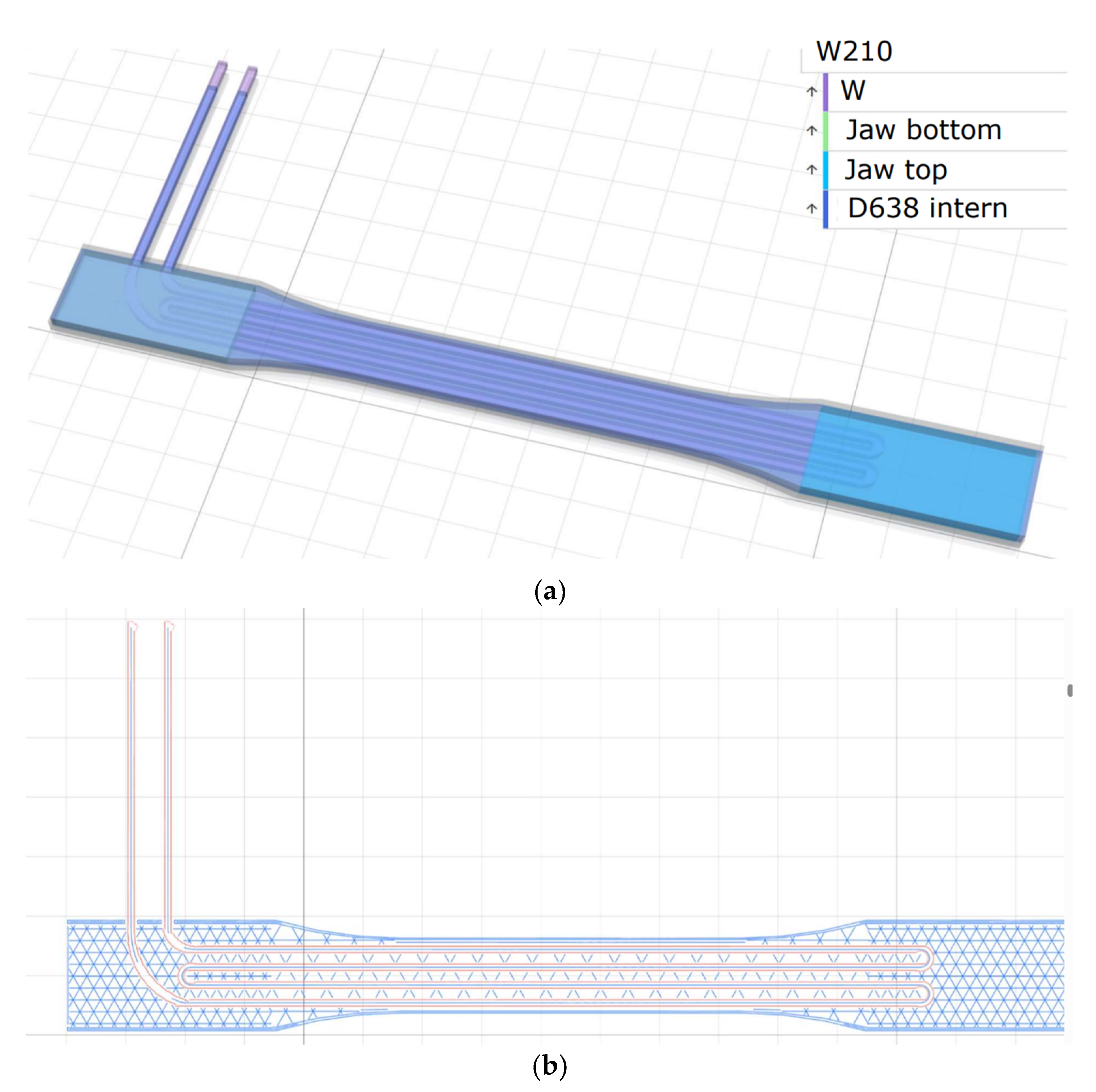
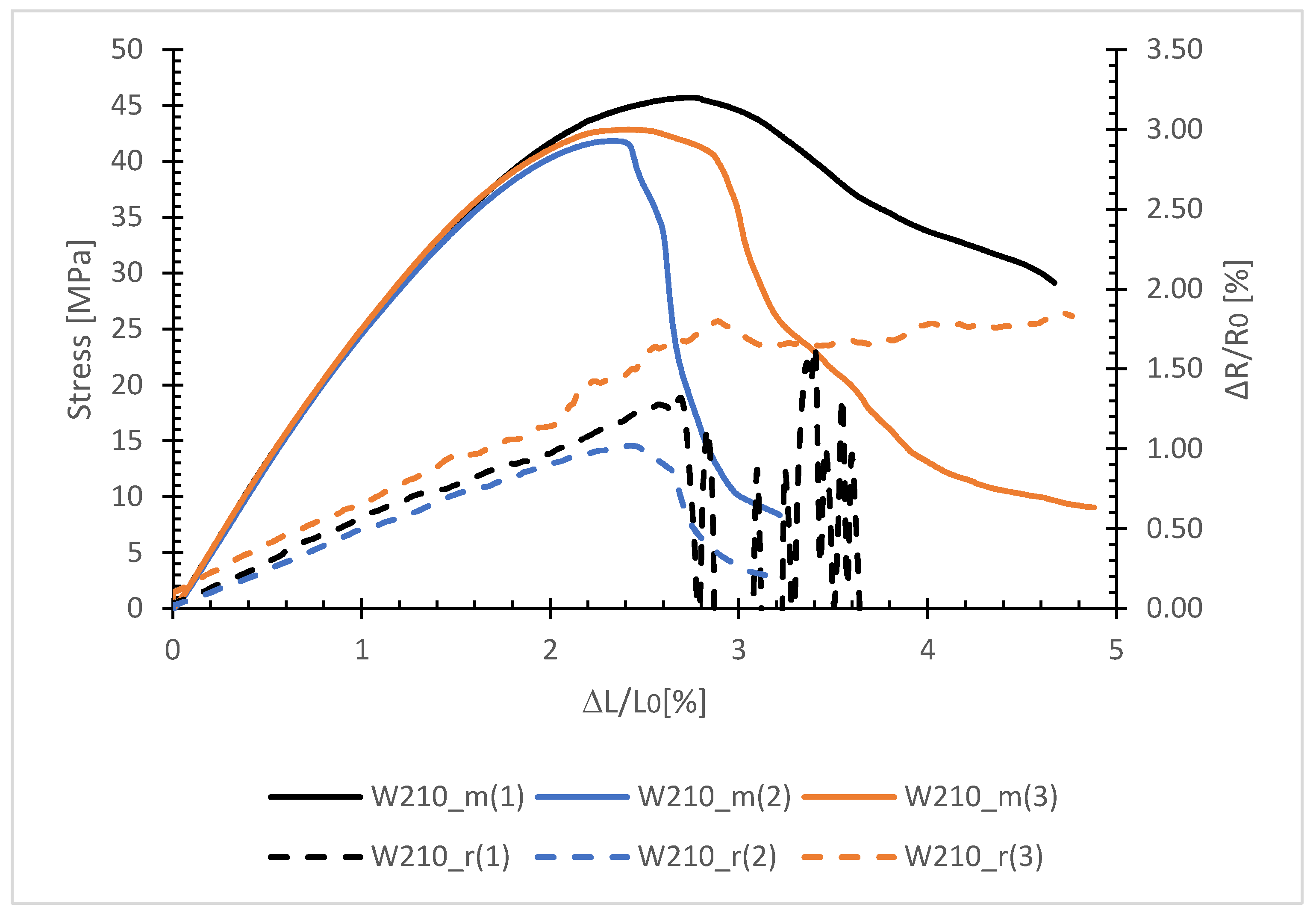
Figure 6 shows the evolution of stress (curve with the annotation “m” for mechanical) and relative resistivity (curve with the annotation “r” for resistivity) as a function of relative elongation for the W-shape sample with 10% internal density and 2 layers of resistive elements. There are three distinct cases of evolution in resistivity.
The mean Young’s modulus is 2727.30 MPa with a standard deviation of 53.59 MPa. While the average Rm is 43.49 MPa with a standard deviation of 2 MPa. In the elastic period, the trend is similar for all 3 curves, but significant variability is visible in the plastic period up to failure. The introduction of continuous carbon fiber leads to a significant improvement in mechanical properties as demonstrated by Kabir et al. [
16].
In terms of relative resistivity, the average initial resistivity is 46.46 Ω with a standard deviation of 0.53 Ω. The three curves in the elastic zone also show a similar trend. The average GF at 1.6% elongation is 0.53 with a standard deviation of 0.07. The value of the average gauge factor is very similar to those obtained in a similar experiment by Yao et al. [
14], but with specimens printed in another material, PLA, and fitted with only 3000 fibers inserted manually during manufacture. A single pass of the fiber through the sample. The average GF in the elastic zone is 0.59 with a standard deviation of 0.13.
However, after 2% relative elongation, the electrical signal shows different signals. Curve W210-r(2) has a maximum of 1% before decreasing to 0%. Curve W210-r(3) continues to follow the trend of the plastic zone and continues to grow. Finally, Curve W210-r(1) shows significant oscillations in the signal. Two distinct zones are visible: behavior in the elastic zone and behavior in the plastic zone. Behavior in the elastic zone is similar to that observed by Galos et al. [
18], i.e., a linear resistivity zone in relation to relative elongation.
In this zone, the adhesion of the carbon fiber to the matrix produces a repeatable signal response directly related to the chosen shape.
Several cases are visible in the plastic deformation zone:
Perfect adhesion between fiber and matrix (W210_r(1) curve) with progressive breakage: a strong variation in the resistive signal is present due to progressive fiber breakage inside the filament adhered to the matrix. A signal is still visible because the connection is ensured by the remaining fibers.
Perfect adhesion between fiber and matrix (W210_r(2) curve) with sharp breakage: the resistive signal is the image of mechanical behavior, with a maximum detected in the same zone as for stress. Sample rupture is marked, with perfect breakage of the carbon fiber leading to loss of signal.
Poor adhesion between fiber and matrix (W210_r(3) curve): the resistive signal continues to increase as the fiber no longer adheres to the matrix. This means that the fiber slides during tensile stress, and that the signal obtained is only the behavior of the fiber tension. Drop-out mainly takes place in the plastic zone, as the behavior of the matrix changes in this area.
3.3. With U- and W-Shaped Carbon Fiber
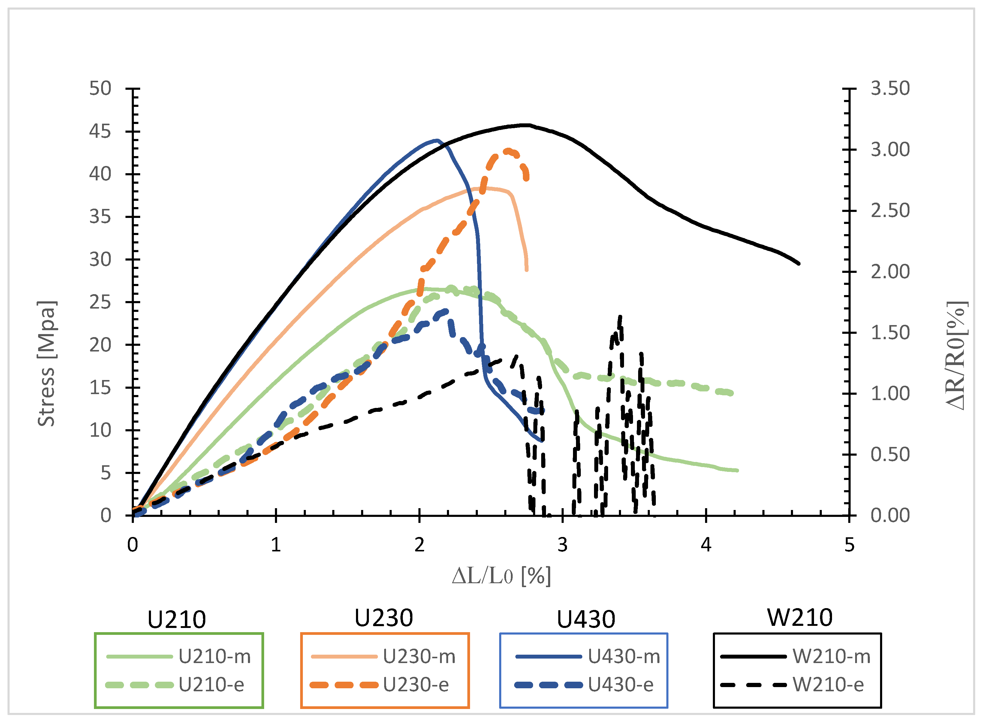
Figure 7 shows the evolution of stress and resistivity relatives in relation to the elongation relative for different cases (U-shape/W-shape).
Table 2 gives a summary of the results obtained during the test campaign, including mechanical properties, resistivity and gauge factor.
An increase in internal density from 10% to 30% leads to improved mechanical properties, as shown by the U210-m and U230-m curves. Young’s modulus increases from 1.69 GPa to 2.04 GPa while Rm increases from 24.57 MPa to 31.75 MPa. Increasing the resistive element layer also leads to improved mechanical properties, with a Young’s modulus of 2.75 GPa and an Rm of 47.65 MPa.
The double passage of two layers of the resistive element (U-shape) results in an increase of over 700 MPa compared with no continuous fiber. By doubling the passage through the sample (W-shape), the increase is over 1.3 GPa. This shows that carbon fiber makes a significant contribution to mechanical performance. The number of layers of carbon fiber improves the mechanical behavior of the sample. At constant carbon fiber lengths, i.e., W210 and U430, the superposition of 2 layers results in improved mechanical properties than a double passage in the same plane of the sample. Stresses are shared between the four layers, resulting in greater strength than with two layers.
For an equivalent fiber length of U430 and W210, the elastic behavior is similar. The fibers are positioned on the different layers in the same direction as the stress. This proves that the mechanical stress is distributed on the carbon fibers and not on the matrix. The mechanical behavior is therefore improved following the introduction of the fibers, but the doubling of the passage in a plane or the superposition has no influence on this improvement.
The change in shape of the resistive element from W to U leads to a deterioration in mechanical properties, with a reduction in Young’s modulus of 1.64 GPa and an Rm of 18.5 MPa. In order to obtain a similar Young’s modulus and Rm with the U-shape, the number of layers of resistive elements must be doubled and the internal filling increased by 20%. This leads to an increase in the length of the resistive element, influencing the initial resistance. This is justified by Pouillet’s law, which says:
where
is the resistivity (in Ωm),
(in m) is the length of the resistive element, and
S (in m
2) is the cross-section of the resistive element. In the case of the W-shape, the length is twice as long as the U-shape, thus increasing resistance.
This has an impact on relative resistivity, as evidenced by the slope of the curve for the W-shape. At constant current, increasing the length of the resistive element leads to a decrease in relative resistivity. This demonstrates the sensitivity of the resistive signal, which is directly related to the length of the resistive element. In the case of the U-shape, detection of the fiber’s disengagement from the matrix is more easily visible due to the sensitivity of the signal.
The average GF at 1.6% elongation is 0.53 for W210-r, while the other GFs are close to 0.717. The GF of sample U210-r is 0.789, that of sample U230-r is 0.745, and that of sample U430-r is 0.752. This is represented by curves with the same inclination for the U-shape over the elastic period, whereas the inclination of the W-shape curve is less significant.
The results shown in
Table 2 were obtained with Smooth PA specimens through which 6000 or 12,000 fibers passed twice (U-shape) or four times (W-shape). The average GF in the elastic zone for U-shape is 0.717 with a standard deviation of 0.10. For the W-shape, the average gauge factor is 0.503 with a standard deviation of 0.07.
Although the matrix is not identical to PLA/Nylon proposed by Yao et al. [
14], the results obtained during the test campaign are comparable. GF is not directly influenced by the number of fibers in the sample. However, the placement of the resistive element in the material is important. Young’s modulus is higher when the number of passes through the cross-section increases, which results in improved mechanical properties. This leads directly to a reduction in GF, as the relative elongation will be greater during the same load.
On the other hand, the standard deviation suggests that repeatability is greater when the number of passes through the section is increased. This can be explained by the automation of fiber placement in the sample compared to Yao’s approach [
14]. Nevertheless, it also has a significant impact on the adhesion of the fiber to the matrix. Having several passes increases the probability of the fiber being adhered to the matrix, resulting in a lower standard deviation.
The main limitation is the serpentine strategy that can be inserted into the sample. The number of passes is limited by the size of the part. In the case of this study, it was impossible to explore a serpentine longer than W because of the space required.

 ,
, 


