1. Introduction
In recent years, there has been a rapid surge in the advancement of eco-friendly green composites, signifying a groundbreaking transformation in materials science and engineering [
1,
2,
3]. These advancements have been driven by the increasing global imperative to mitigate environmental challenges and transition towards more sustainable manufacturing practices. Sustainable composites, often derived from renewable, bio-based resources, offer multifaceted advantages, including reduced carbon footprint, reduced reliance on non-renewable resources, and properties comparable to traditional composites [
4]. Additionally, they open new possibilities for closed-loop recycling and circular economies, reducing waste and promoting efficient resource utilization. Now that global challenges intensify, such as climate change, resource scarcity, and environmental pollution, sustainable composites emerge not only as an alternative but also as an essential evolution in material design, aligning technological progress with environmental stewardship [
5].
Natural fibers, such as wood fibers, cotton fibers, bamboo fibers, and silk, play a pivotal role in the development of sustainable green composites [
6,
7,
8]. These plant-based and animal-based fibers, derived from renewable sources, such as wood, hemp, flax, and jute, offer significant environmentally friendly advantages due to their biodegradability, recyclability, low carbon footprint, cost-effectiveness, and minimum generation of non-recyclable waste. The dominant chemical composition of natural fibers usually contains lignin, cellulose, and hemicellulose, which can be used as the filler materials within a polymer matrix as the renewable resource to produce green composites [
9,
10,
11]. Natural fibers can enhance the mechanical properties of green composites, such as strength and stiffness, while maintaining lightweight and sustainable characteristics. This combination of eco-friendliness, renewability, low cost, and outstanding performance makes natural fibers the essential components in the development of sustainable green composites, significantly contributing to a greener and more environmentally responsible future for materials science and engineering. However, the integration of natural fibers and polymers for the development of green composites requires processing optimization considering the natural characteristics of both materials. For example, most natural fibers are hydrophilic, whereas many polymers are hydrophobic in nature [
12]. This mismatch can lead to poor interfacial adhesion between the fibers and the matrix, potentially reducing the mechanical properties of green composites. Additionally, natural fibers tend to absorb moisture from the environment, leading to a negative impact on the mechanical and dimensional stability of composites [
13]. To improve compatibility between fibers and polymers, surface treatments, such as alkali treatment, silane treatment, or the use of coupling agents, are usually needed. Therefore, the development of novel processing and manufacturing technologies are urgently needed for the broad applications of sustainable green composites.
Additive manufacturing (AM) offers promising solutions to prepare, process, and fabricate sustainable composites that combine renewability with beneficial functionalities for broad engineering applications. Natural fibers, recycled materials, and biodegradable polymers have been integrated and applied to the 3D printing processes, yielding composites with reduced environmental impacts [
14,
15,
16]. Multiple AM processes, including fused deposition modeling (FDM), selective laser sintering (SLS), stereolithography (SLA), and direct ink writing (DIW), have been studied for the development of innovative printing techniques that can optimize sustainable composite fabrication [
17,
18,
19,
20,
21]. As one of the most common methods for 3D printing of green composites, FDM-based AM uses filaments comprising natural fibers or recycled materials blended with biodegradable polymers and extruded materials layer by layer to create intricate 3D products and components. FDM’s versatility allows for the precise placement of reinforcing fibers within the printed object, enhancing its mechanical strength while maintaining an eco-friendly profile. For example, Cali et al. employed FDM-based 3D printing technology and processed five organic bio-composite filaments, including polylactic acid (PLA) polymer with hemp, weed, tomato, carob, and pruned fillers. Each natural agricultural additive generated different mechanical/physical properties, such as tensile strength, elasticity, density, porosity, and a strong visual and tactile identity [
18]. Although FDM-based 3D printing excels in processing thermoplastic biopolymers, polymers in other forms, such as powders, require additional AM approaches for 3D printing of sustainable composites.
SLS-based 3D printing technology provides an alternative solution for the AM of sustainable composites. In SLS, a high-powered laser selectively sinters powdered sustainable composite materials layer by layer, allowing for the creation of intricate and robust structures [
22]. SLS technology not only enhances the mechanical properties of these sustainable composites but also minimizes material wastage as unused powders that can be recycled for future prints. This approach aligns perfectly with the growing emphasis on sustainable practices in various industries, such as aerospace, healthcare, and architecture, where the production of lightweight, strong, and eco-friendly components is of paramount importance [
23,
24]. Additionally, there is a growing emphasis on the development of sustainable composite filaments and powders for commercial 3D printers, broadening the accessibility of these materials to a wider audience [
25]. Recently, Idrises et al. reported an investigation to develop the AM of prosopis chilensis and polyethersulfone composite using SLS-based 3D printing. A comprehensive mechanical characterization was carried out to fully understand key parameters, such as bending and tensile strengths. Additionally, post-processing infiltration was employed to further enhance the performance of 3D-printed green composites [
26].
Bio-based polymer resins derived from renewable resources have been developed for the 3D printing of green composites using the SLA and DIW AM methods [
27,
28,
29]. Natural products, such as soybean oil, linseed oil, and even starch, have been investigated for resin development. Micro and nano natural fibers, such as cellulose nanocrystals, can be employed to further enhance the mechanical properties of bio-based resin [
30]. However, SLA- and DIW-based 3D printing of green composites are limited by a few technical challenges, including effective bonding between the fiber and polymer matrix and consistent rheological properties for high printability throughout the entire printing process.
Although significant efforts have been made to develop novel materials and manufacturing processes for sustainable composites, challenges related to material compatibility, mechanical properties, and post-processing techniques still limit the broad engineering applications of certain green composites. Additionally, it is urgently needed to identify the material–process–structure–property relationship of green composites so that certain knowledge can be applied to the design and development of novel products using eco-friendly and recyclable green composites. Moreover, substantial progress is urgently needed to further improve environmental friendliness and customizable manufacturing processes with potential applications in industries, including aerospace, automotive, and consumer goods.
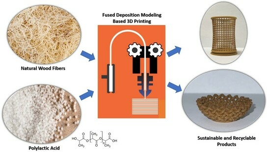
In this paper, we reported an investigation of 3D printing of sustainable composites composed of PLA and wood fibers. The novelty of this paper focuses on the identification of material–process–structure–property relationships for AM-processed green composites and their extended applications on honeycomb structures. FDM-based 3D printing technology was employed for the AM process of wood fiber-enhanced composites. Critical properties of the 3D-printed green composites, including density, porosity, and tensile strength and modulus, were systematically characterized. Microstructures were characterized using both optical microscope and scanning electron microscope (SEM). Non-contact and full-field digital image correlation (DIC) technology was employed to obtain accurate local strain concentration. Additionally, the wood fiber-enhanced composites were used to 3D print honeycomb structures, and DIC technology was employed to identify the failure mechanism of FDM 3D-printed green composites. The research outcomes of this paper can be useful for further investigation of sustainable composites as the core material for potential ultra-light sandwich composite applications in aerospace, automotive, and mechanical applications.
3. Results and Discussion
3.1. Microstructural Characterization of Wood Fiber Reinforced Composites
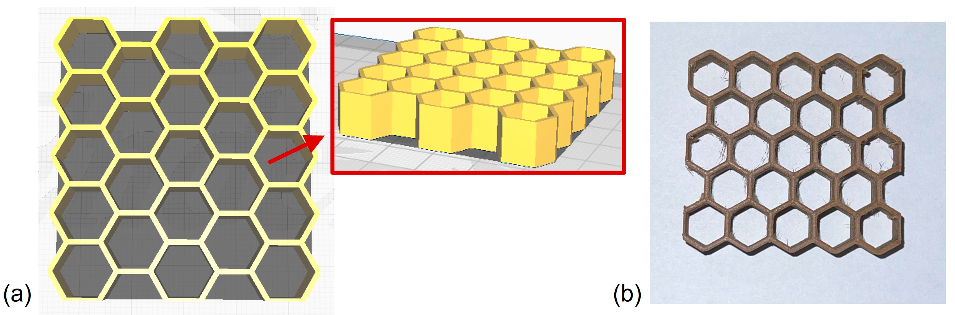
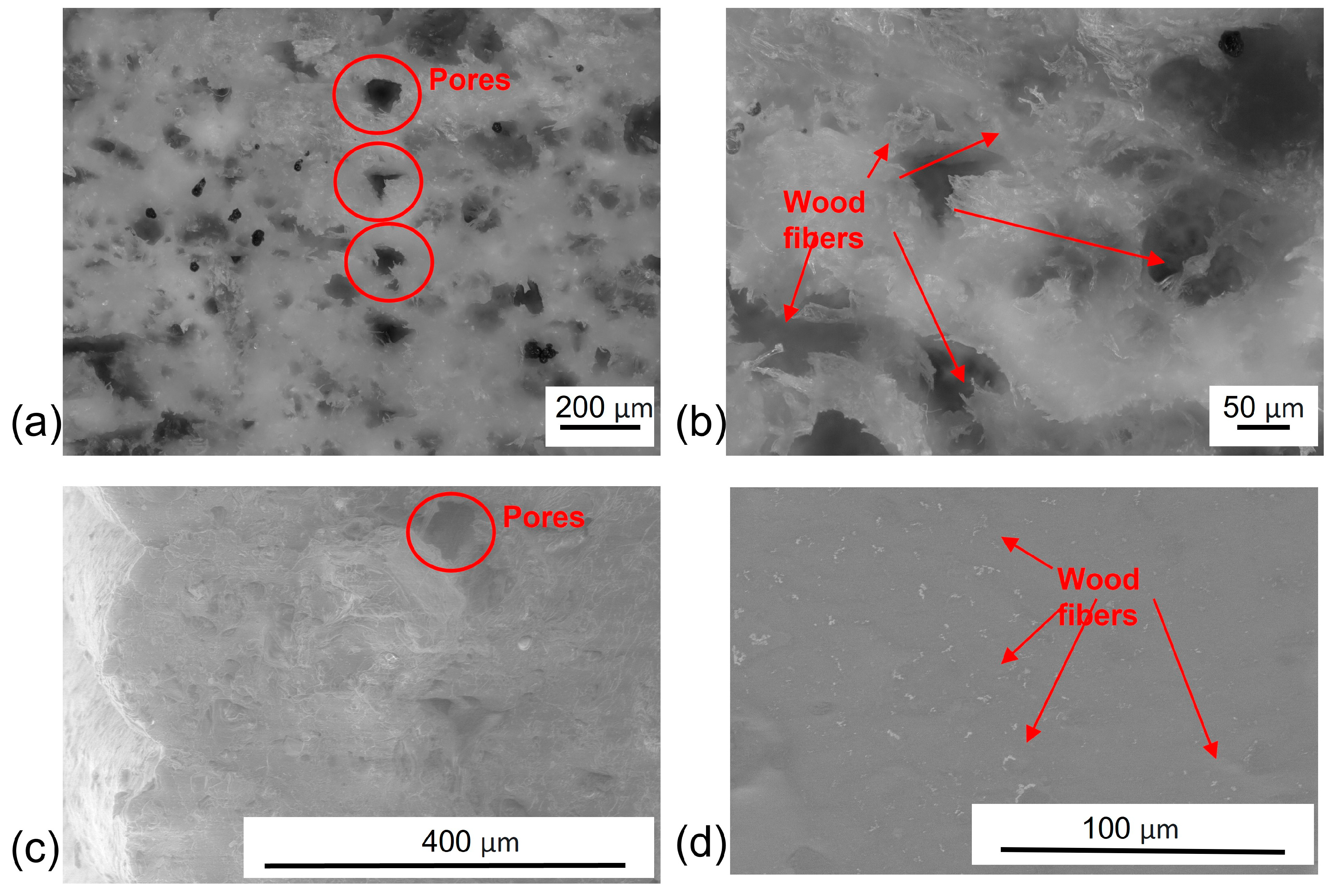
As shown in
Figure 2, wood fiber reinforcements were uniformly distributed within the 3D-printed sustainable composites without any evident agglomerations, indicating the improvement of mechanical properties provided by the wood fiber fillers within the PLA matrix. Additionally, embedded pores were observed in the optical and SEM images. To better understand the characteristics of the pores, ImageJ software was used to analyze the geometries of the pores. The measured diameters of the embedded pores were in the range of 35 µm to 80 µm. Although 100% infiltration density was used during the design and G-code generation for FDM-based 3D printing, the pores were potentially generated due to the under-extrusion or over-extrusion, high print speed, and layer height. Under-extrusion could cause incomplete layers, whereas over-extrusion could lead to bulging and poor adhesion between adjacent lines. Fast print speed could reduce adhesion between layers and create pores in printed composites. A reduction in layer height could potentially produce smoother surface and denser composites but would increase print time and reduce print efficiency.
3.2. Density and Porosity of 3D-Printed Wood Fiber Composites
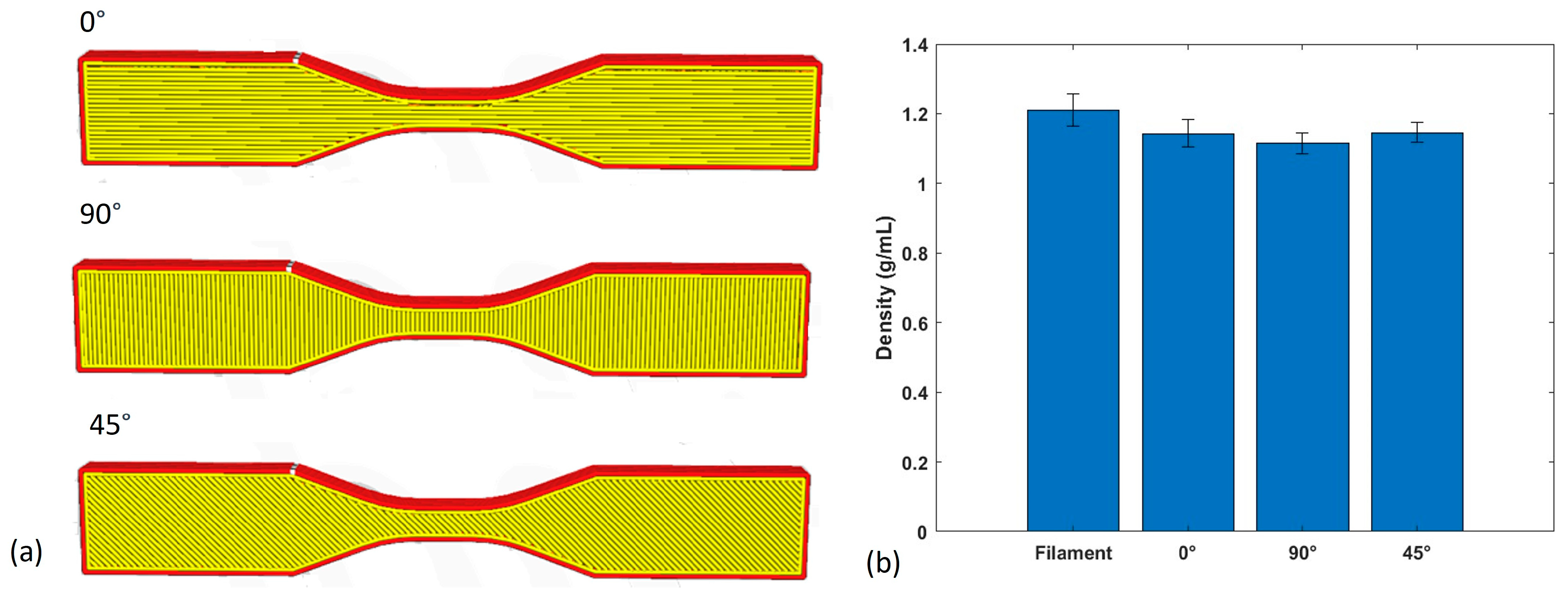
The printing orientations of the three types of composite samples are shown in
Figure 3a. In the case of the 0° print orientation, the printing direction was perfectly aligned with the gauge length of the dogbone samples, thus running parallel to it. Conversely, the 90° print orientation indicated that the printing direction was perpendicular to the gauge length of the dogbone samples. For the 45° print orientation, the angle between the print direction and the gauge length direction was precisely 45°, demonstrating an oblique arrangement and potential design flexibility for FDM-processed AM products. Importantly, it is worth noting that the print direction remained consistent for all layers within each sample, ensuring uniformity throughout the fabrication process.
The measured density served as a direct indicator of the average porosity within the 3D-printed composites in this study. Considering the fabrication of the wood fiber composite filament involved an extrusion process conducted under high-temperature and high-pressure conditions, it is a valid assumption that the filament achieved a state of full density. Therefore, the density of this filament was adopted as the reference for comparative analysis of the densities of the 3D-printed composites. The average densities and related standard deviations of the three types of composites is shown in
Figure 3b. It is noted that the average densities of composites with 0°, 90°, and 45° print orientations were 1.14 g/mL, 1.12 g/mL, and 1.15 g/mL, respectively, and the density of the composite filament was 1.21 g/mL. According to Equation (1), the calculated porosities of these three types of 3D-printed composites were 5.79%, 7.44%, and 4.96%. The low porosity of the FDM-processed composites indicated that the 3D-printed materials and parts should have outstanding mechanical properties and performance.
3.3. Mechanical Properties of 3D-Printed Composites
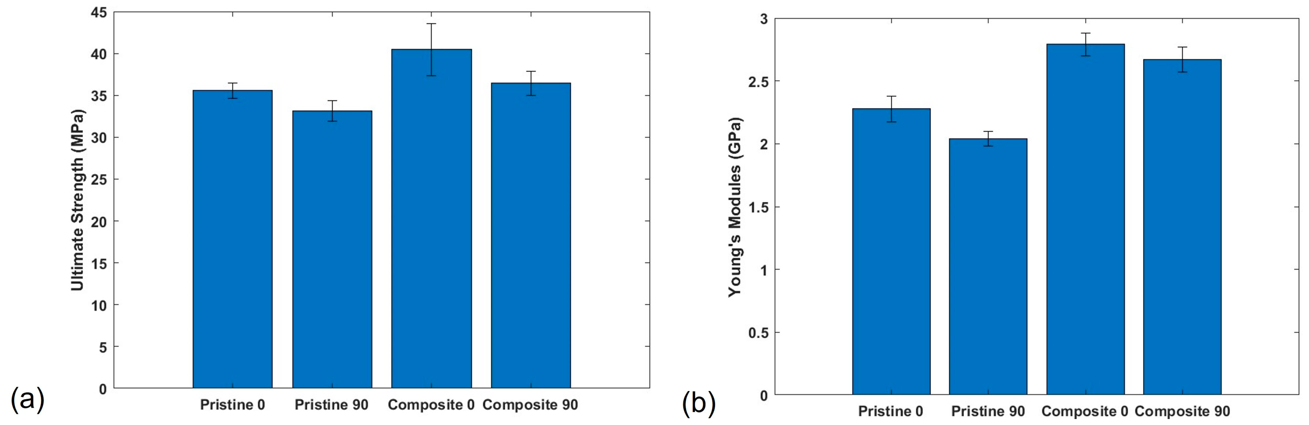
The tensile properties of the 3D-printed composites and pristine PLA polymers with print orientations of 0° and 90° were characterized to evaluate the material’s tensile properties, particularly its strength and elasticity, using dogbone shape samples following the ASTM D638 standard. Quasi-static tensile loads were applied and DIC images were taken simultaneously during all the tensile tests. Three experiments were conducted for each type of sample to ensure the repeatability of the experimental results. The DIC technology not only allowed the measurement of 3D strain fields but also identified the local stress and strain concentrations using tensile testing, indicating the damage initiation and growth of the sample for detailed fracture analysis. Compared to pristine PLA, wood fiber-reinforced composites showed improved ultimate tensile strengths due to the reinforcement of uniformly dispersed wood fiber in the PLA matrix, as shown in
Figure 4a. Notably, when the printing direction was set to 0°, the ultimate tensile strength of wood fiber composite was 38.91 MPa, which resulted in a 10.79% increase compared to the ultimate tensile strength of pristine PLA of 35.12 MPa. Similarly, when the print orientation was set at 90°, the ultimate tensile strength of wood fiber composite was 36.27 MPa, which was also 5.84% increase compared to the ultimate tensile strength of pristine PLA of 34.27 MPa. Notable improvements were observed in the Young’s modulus of the 3D-printed specimens. For the wood fiber-reinforced composites aligned at 0°, the Young’s modulus was measured at 2.79 GPa, indicating a 21.83% increase from the PLA sample with 2.29 GPa Young’s modulus. Additionally, the wood fiber-reinforced composites oriented at 90° exhibited a Young’s modulus of 2.67 GPa, which was a 30.88% increase compared to the PLA dogbone samples printed in the same orientation, with a Young’s modulus of 2.04 GPa.
These enhancements of mechanical properties in 3D-printed composites could be due to multiple factors, such as the alignment of wood fibers along the printing direction as well as the strong adhesion between wood fiber and PLA polymers. Aligning wood fibers along the 3D printing direction is critical to improve mechanical performance of 3D-printed sustainable composites. During FDM-based 3D printing, the nozzle’s movement creates shear stress within the extrude composite as it is pushed through the nozzle and deposited onto the build platform. This shear stress improves the alignment of wood fibers within the polymer matrix material. Additionally, there is a shearing action between the newly deposited layer and the previous layer, which also encourages alignment of wood fibers parallel to the layer interfaces. Other printing parameters, such as extrusion speed, nozzle temperature, and layer height, should be adjusted to control the shear forces applied to the composites during printing. Optimizing these parameters can help achieve the desired wood fiber alignment. These findings emphasized the critical role that printing orientation and beneficial fillers played in determining the mechanical performance of 3D-printed sustainable composite structures, providing valuable insights for optimizing design and AM fabrication processes for the development of future sustainable and recyclable composites.
Non-contact DIC strain field measurement technology was employed during all the tensile tests to ensure the precise strain measurement in the gauge section of each dogbone sample. The employed DIC system utilized a pair of synchronized cameras to capture images of the specimen surface cameras. Before loading or deformation, a random speckle pattern was painted on the sample surface, serving as a reference image. During deformation, the cameras simultaneously captured images, which were then compared to the reference images using sophisticated image correlation algorithms. By analyzing the displacement of the speckle patterns between the reference and deformed images, full-field 3D surface deformations and, subsequently, the strain fields were derived. The precision and accuracy of this method depended upon various factors, including the quality of the speckle pattern, camera resolution, and the calibration process.
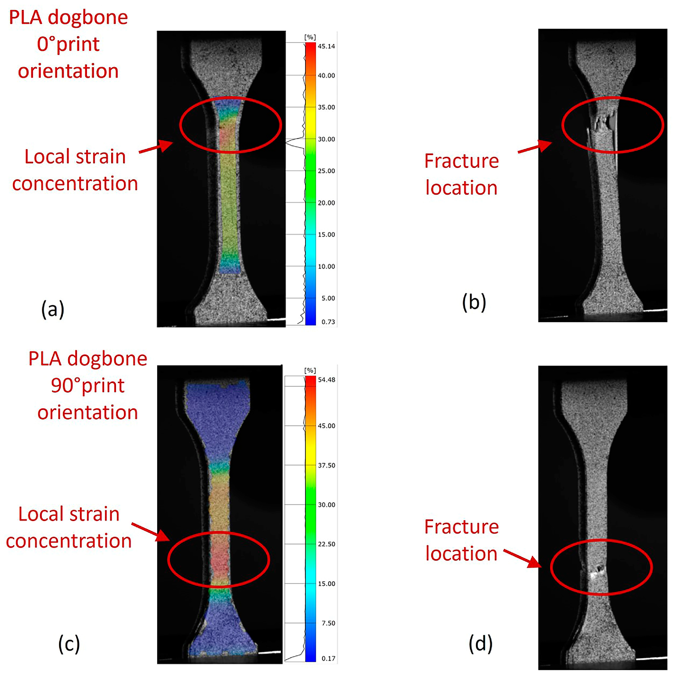
In this study, as the local strains in 3D space were all measured simultaneously using the DIC, local stress and strain concentrations were clearly identified for the prediction of potential fracture locations. As shown in
Figure 5a, the local stress and strain concentration was clearly identified near the top of the gauge section of pristine PLA dogbone sample after the local stress passed the composite yield stress, generating plastic deformation in the local section of the dogbone gauge area. The final fracture also happened at the stress concentration location, as shown in
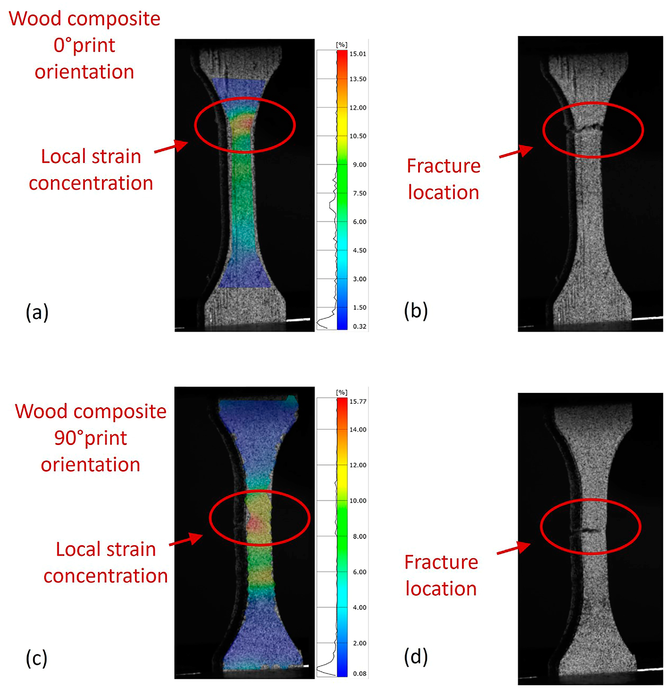
Figure 5b. Similar performance was observed in PLA printed in 90° print orientation as well as the wood fiber composite samples, as shown in
Figure 5c,d and
Figure 6. Additionally, the average tensile strain
in the vertical direction was used for the generation of stress–strain curves. The average tensile strain measured from the DIC system was more accurate than the average strain recorded from the Instron mechanical testing system due to the potential experimental errors introduced by the tab section of the dogbone samples.
3.4. Mechanical Performance and Fracture Mechanism of Honeycomb Structures
Honeycombs have been well recognized as ultra-lightweight structures with outstanding mechanical properties, resulting in numerous promising applications in the fields of architecture, automotive, aerospace, marine, and space applications. Utilizing natural fiber composites in honeycomb design and development can significantly enhance the sustainability and recyclability of honeycombs. However, novel fabrication and in-depth understanding of the novel composite honeycombs’ mechanical properties and performance is still urgently needed.
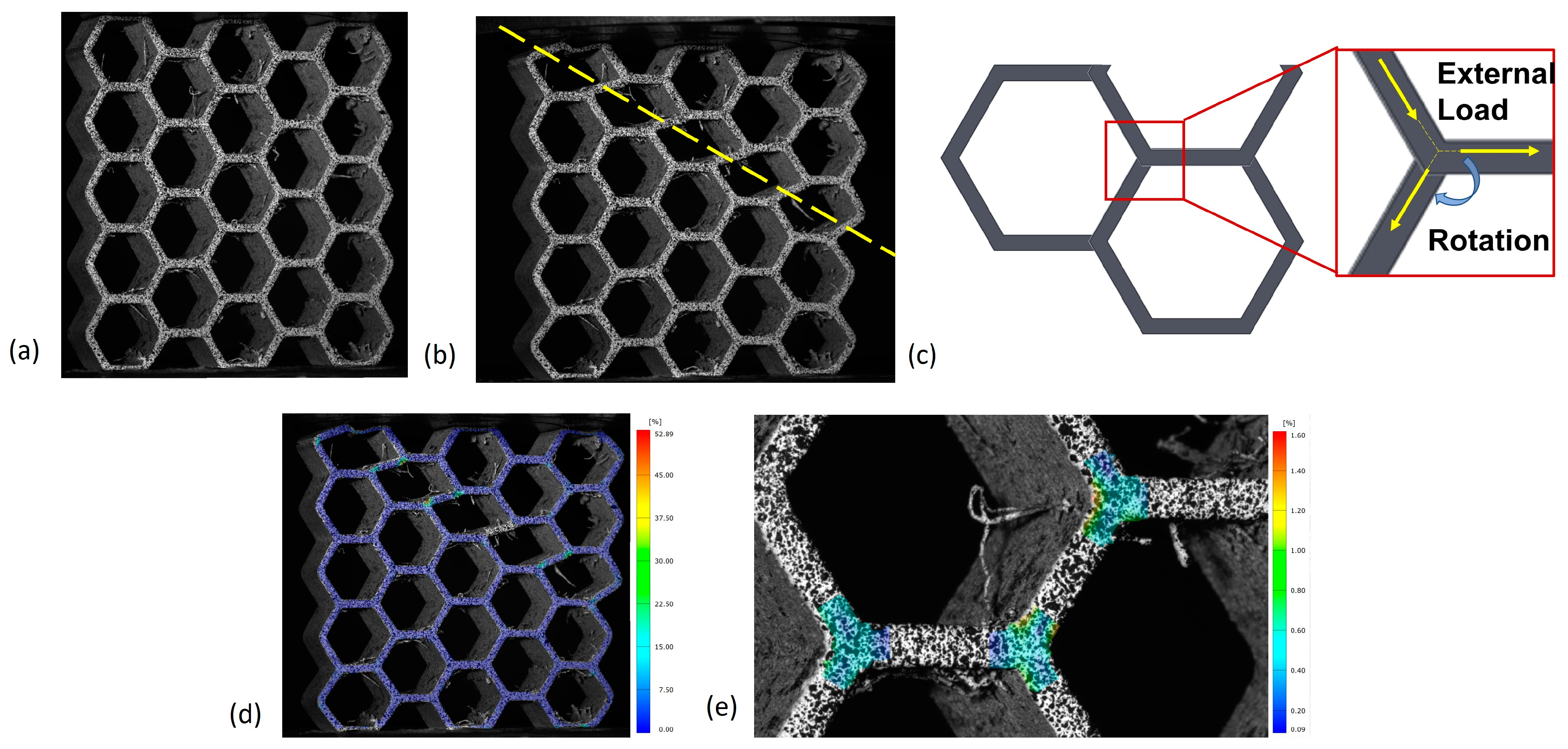
The 3D-printed hexagonal honeycombs were first tested by placing the flat surface of the sidewall on the Instron machine, as shown in
Figure 7a. The top surface of the honeycomb was measured by the DIC system to obtain the 3D strain fields during the mechanical testing. Local normal and shear strains in 3D space were measured, and the equivalent strain, such as the Von Mises strain, could be calculated for further analysis. All the tested samples showed the 45° failure mode during their post-yielding behavior, as shown in
Figure 7b. The local load condition of the joint section of three adjacent cells is shown in
Figure 7c. The applied compressive load caused compressive load applied on the joint area and further compressed two adjacent cell walls, resulting in the local torsional load on the joint. Due to the local torsional load applied at the joint of adjacent honeycomb cells, the joint rotated as the overall compressive load was applied on the top and bottom surfaces, resulting in local stress concentrations and fracture by the end of each test, as shown in
Figure 7e. The entire 3D strain field was recorded, as shown in
Figure 7d.
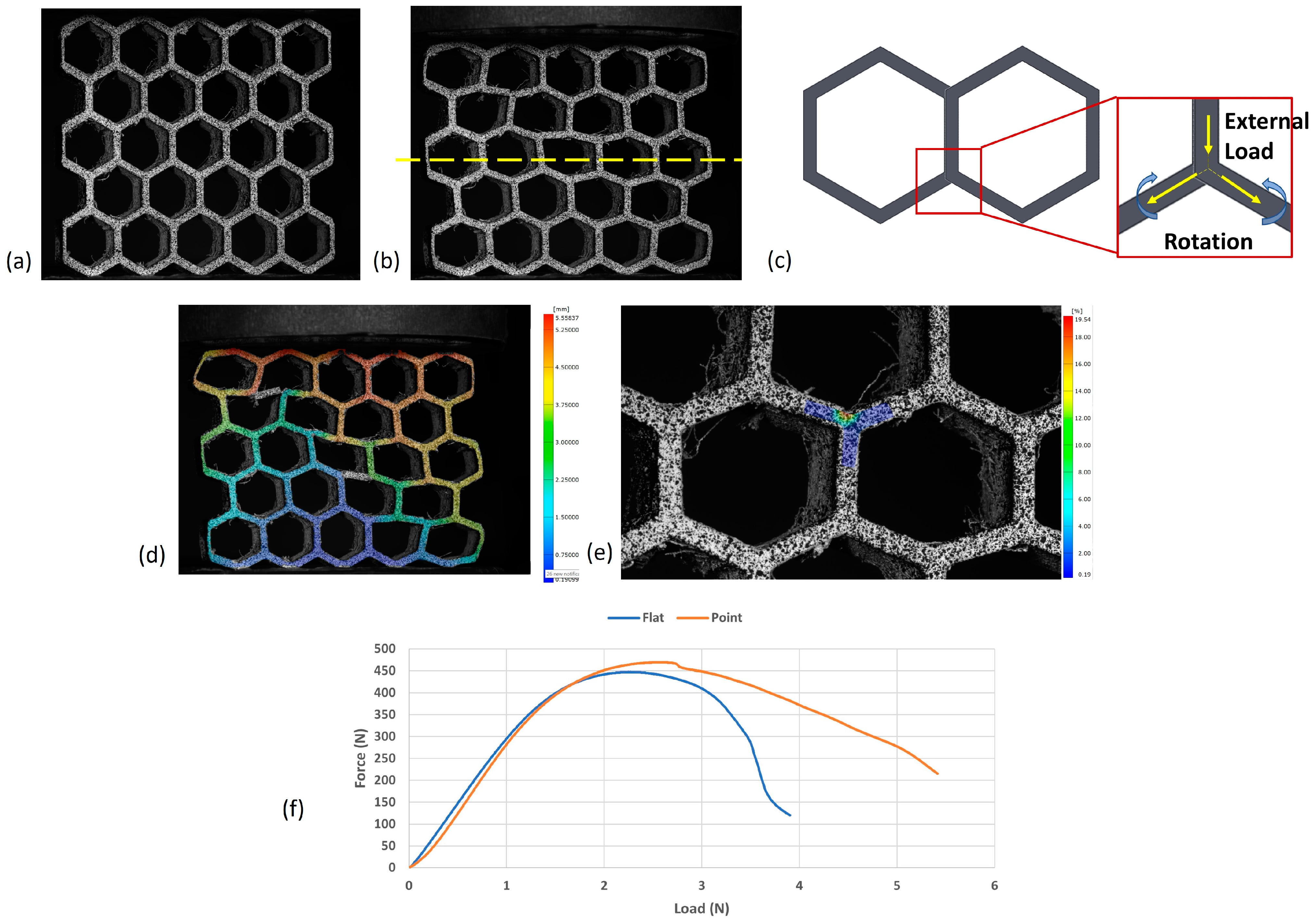
To fully evaluate the performance of the 3D-printed hexagonal honeycombs under compressive loads, new samples with the same dimensions were tested by placing the corners of sidewall on the Instron test plate, resulting in point contact and concentrated compressive loads during the test, as shown in
Figure 8a. The failure mode of the new compressive tests is shown in
Figure 8b. As the external load was vertically applied down to the joint of adjacent cells, the symmetrical cell structures equally distributed the load to each side of the cell walls, leading to the horizontal collapse of the honeycomb. The local loads applied at each joint section of three cells is shown in
Figure 8c. The deformation in the vertical direction of the tested honeycomb sample is shown in
Figure 8d. The top three rows of hexagonal cells were all collapsed after the compressive test; however, the third row showed the most deformation. The local stress concentration of the joint of three adjacent cell walls is shown in
Figure 8e.
The comparison of the honeycomb performance in the two load directions revealed that the 3D-printed hexagonal honeycombs could better distribute to the entire structure when the applied load was parallel to the cell walls. Therefore, increased compressive load could be carried by the honeycombs before collapse and structural failures. The recorded force and displacement data of the two types of experiments proved this conclusion, as shown in
Figure 8f. Although initial stress concentrations were generated at each corner contacting the test plates, the applied compressive force was distributed throughout the honeycomb, leading to the 4.3% increase in the maximum load capacity.
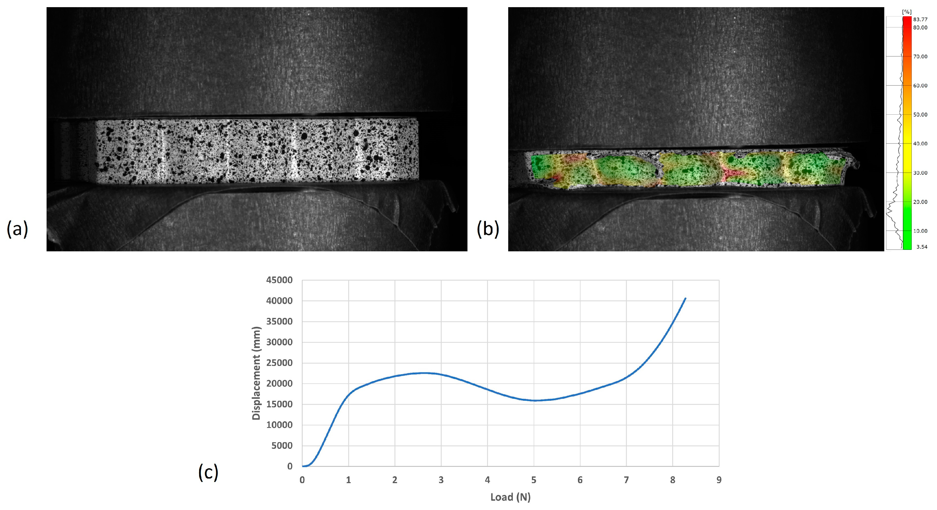
When the compressive load was applied along the height of the honeycomb, the 3D-printed samples showed the highest load capacity and structural stability, as shown in
Figure 9a. Due to the large contact area, all the applied loads could be uniformly distributed throughout the honeycomb structures. Additionally, the cell walls could serve as the stiffeners and further stabilize the honeycomb structure, leading to improved overall structural strengths. The collapsed honeycomb and the equivalent Von Mises strain field after compressive tests are shown in
Figure 9b. The applied force and displacement data are shown in
Figure 9c. Experimental results indicated that the 3D-printed honeycombs carried more than 83 times of the compressive load when the load was applied along the height direction. It is noted that different failure modes, such as buckling, could potentially happen if the height to cell diameter increases when the designs of honeycomb structures change.
3.5. Demonstration of FDM-Based 3D Printing Capability Using Wood Fiber Composites
It is critical to demonstrate the FDM-based 3D printing technology using the wood fiber-reinforced PLA matrix composite with complex geometries. This type of test print can not only be used as the proof-of-concept for sustainable composite AM fabrication but also is part of the process to evaluate the manufacturing readiness levels before real engineering practice. Compared to traditional petroleum-based polymer and composites, wood fiber-reinforced PLA composites can be fully manufactured using recyclable and renewable bio-based materials, presenting an eco-friendly solution for current challenges in sustainability, recyclability, and carbon footprint reduction. Additionally, the demonstration of FDM using sustainable composites allows for intricate geometrical designs that were previously impossible with conventional manufacturing methods. Such AM capabilities pave new ways for innovative product design and multifunctional composite development.
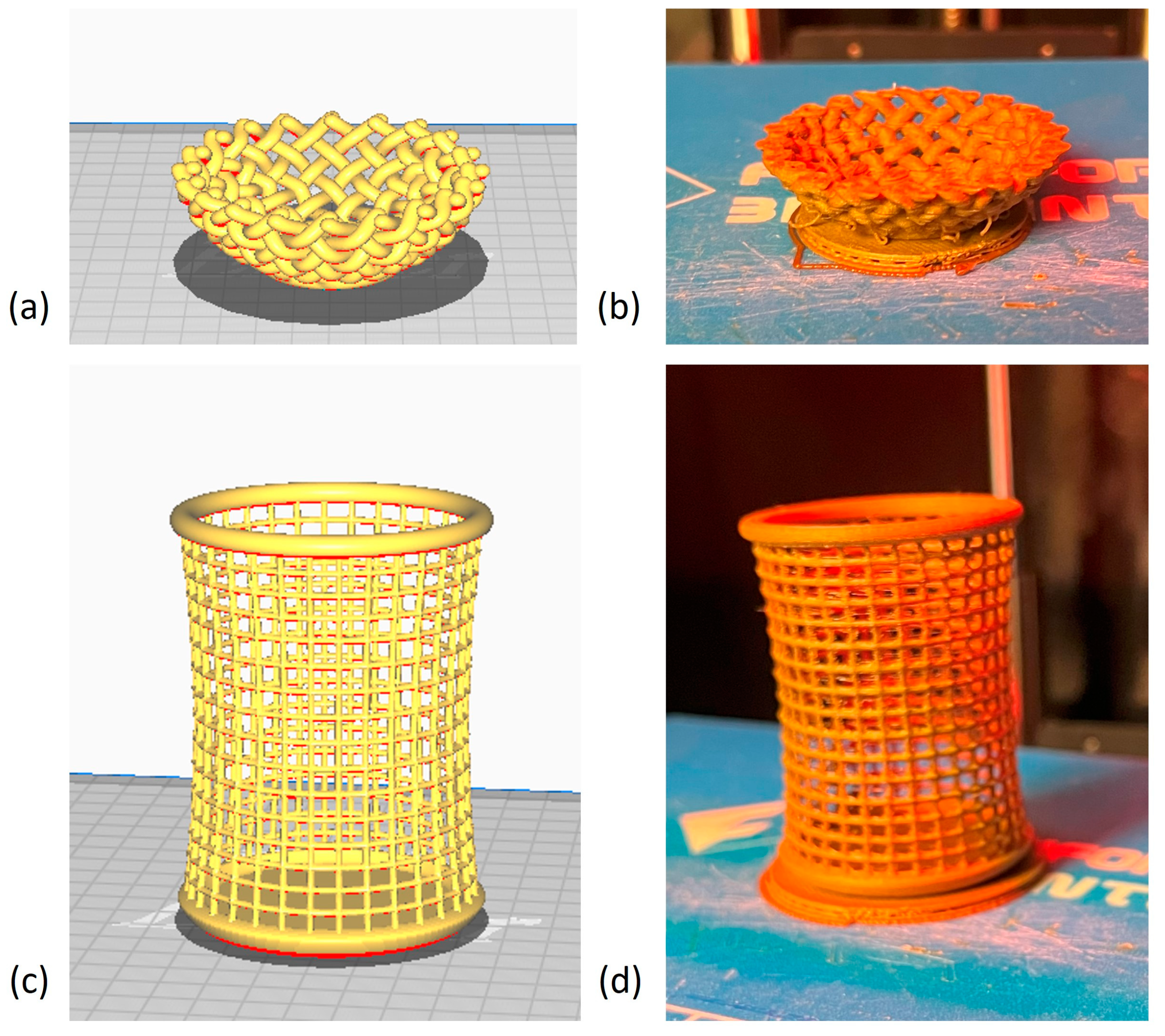
Two CAD models were employed for the test print and demonstration of FDM-based AM technology using the wood fiber-reinforced PLA matrix composites. As shown in
Figure 10, both CAD models have complex geometries and a significant number of hollow structures. The woven bowl CAD model has multiple geometrical features, such as hanging walls and thin contact points of the woven structures. Similarly, the frame bin CAD model also requires precise manipulation of hollow structures and joins. The successful prints of the two models showed that commercial FDM printers can potentially achieve the required structural accuracy, integrity, and quality.


