
The Influence of Nitrogen Flow Rate on the Structure and Properties of Mo-Hf-Y-Si-B-N Coatings
 , ,
, ,
Abstract
:1. Introduction
2. Materials and Methods
3. Results and Discussions
4. Conclusions
Supplementary Materials
Author Contributions
Funding
Data Availability Statement
Acknowledgments
Conflicts of Interest
References
- Bahr, A.; Richter, S.; Hahn, R.; Wojcik, T.; Podsednik, M.; Limbeck, A.; Ramm, J.; Hunold, O.; Kolozsvári, S.; Riedl, H. Oxidation Behaviour and Mechanical Properties of Sputter-Deposited TMSi2 Coatings (TM = Mo, Ta, Nb). J. Alloy. Compd. 2023, 931, 167532. [Google Scholar] [CrossRef]
- Taylor, M.; Perepezko, J.H. Hot Corrosion of Mo–Si–B Coatings. Oxid. Met. 2017, 87, 705–715. [Google Scholar] [CrossRef]
- Perepezko, J.H. High Temperature Environmental Resistant Mo-Si-B Based Coatings. Int. J. Refract. Met. Hard Mater. 2018, 71, 246–254. [Google Scholar] [CrossRef]
- Lemberg, J.A.; Ritchie, R.O. Mo-Si-B Alloys for Ultrahigh-Temperature Structural Applications. Adv. Mater. 2012, 24, 3445–3480. [Google Scholar] [CrossRef] [PubMed]
- Terent’eva, V.S.; Zhestkov, B.E. Multifunctional High-Temperature D5 MAI and M1 MAI Coatings. Russ. J. Phys. Chem. B 2009, 3, 391–396. [Google Scholar] [CrossRef]
- Musil, J.; Zeman, P. Hard A-Si3N4/MeNx Nanocomposite Coatings with High Thermal Stability and High Oxidation Resistance. Solid State Phenom. 2007, 127, 31–36. [Google Scholar]
- Vlček, J.; Potocký, Š.; Čížek, J.; Houška, J.; Kormunda, M.; Zeman, P.; Peřina, V.; Zemek, J.; Setsuhara, Y.; Konuma, S. Reactive Magnetron Sputtering of Hard Si–B–C–N Films with a High-Temperature Oxidation Resistance. J. Vac. Sci. Technol. A Vac. Surf. Film. 2005, 23, 1513. [Google Scholar] [CrossRef]
- He, J.; Zhang, M.; Jiang, J.; Vlček, J.; Zeman, P.; Steidl, P.; Meletis, E.I. Microstructure Characterization of High-Temperature, Oxidation-Resistant Si-B-C-N Films. Thin Solid Film. 2013, 542, 167–173. [Google Scholar] [CrossRef]
- Šímová, V.; Vlček, J.; Zuzjaková, Š.; Houška, J.; Shen, Y.; Jiang, J.; Meletis, E.I.; Peřina, V. Magnetron Sputtered Hf–B–Si–C–N Films with Controlled Electrical Conductivity and Optical Transparency, and with Ultrahigh Oxidation Resistance. Thin Solid Film. 2018, 653, 333–340. [Google Scholar] [CrossRef]
- Farhadizadeh, A.; Vlček, J.; Houška, J.; Haviar, S.; Čerstvý, R.; Červená, M.; Zeman, P.; Matas, M. Effect of Nitrogen Content on High-Temperature Stability of Hard and Optically Transparent Amorphous Hf-Y-Si-B-C-N Coatings. Ceram. Int. 2023, 49, 6086–6093. [Google Scholar] [CrossRef]
- Kotrlová, M.; Zeman, P.; Houška, J.; Šímová, V.; Procházka, M.; Čerstvý, R.; Haviar, S.; Vlček, J. Enhancement of High-Temperature Oxidation Resistance and Thermal Stability of Hard and Optically Transparent Hf–B–Si–C–N Films by Y or Ho Addition. J. Non. Cryst. Solids 2021, 553, 120470. [Google Scholar] [CrossRef]
- Kiryukhantsev-Korneev, F.V.; Lemesheva, M.V.; Shvyndina, N.V.; Levashov, E.A.; Potanin, A.Y. Structure, Mechanical Properties, and Oxidation Resistance of ZrB 2, ZrSiB, and ZrSiB/SiBC Coatings. Prot. Met. Phys. Chem. Surf. 2018, 54, 1147–1156. [Google Scholar] [CrossRef]
- Kiryukhantsev-Korneev, P.V.; Potanin, A.Y. Structure, Mechanical Properties, and Oxidation Resistance of MoSi2, MoSiB, and MoSiB/SiBC Coatings. Russ. J. Non-Ferrous Met. 2018, 59, 698–708. [Google Scholar] [CrossRef]
- Glechner, T.; Oemer, H.G.; Wojcik, T.; Weiss, M.; Limbeck, A.; Ramm, J.; Polcik, P.; Riedl, H. Influence of Si on the Oxidation Behavior of TM-Si-B2±z Coatings (TM = Ti, Cr, Hf, Ta, W). Surf. Coat. Technol. 2022, 434, 128178. [Google Scholar] [CrossRef]
- Kiryukhantsev-Korneev, P.V.; Iatsyuk, I.V.; Shvindina, N.V.; Levashov, E.A.; Shtansky, D.V. Comparative Investigation of Structure, Mechanical Properties, and Oxidation Resistance of Mo-Si-B and Mo-Al-Si-B Coatings. Corros. Sci. 2017, 123, 319–327. [Google Scholar] [CrossRef]
- Kiryukhantsev-Korneev, P.V.; Sytchenko, A.D.; Sviridova, T.A.; Sidorenko, D.A.; Andreev, N.V.; Klechkovskaya, V.V.; Polčak, J.; Levashov, E.A. Effects of Doping with Zr and Hf on the Structure and Properties of Mo-Si-B Coatings Obtained by Magnetron Sputtering of Composite Targets. Surf. Coat. Technol. 2022, 442, 128141. [Google Scholar] [CrossRef]
- Kiryukhantsev-Korneev, P.V.; Kudryashov, A.E.; Sheveyko, A.N.; Orekhov, A.S.; Levashov, E.A. Improving the Oxidation Resistance of Inconel 718 High-Temperature Nickel Alloy Using Combined Surface Engineering Technology. Lett. Mater. 2020, 10, 371–376. [Google Scholar] [CrossRef]
- Kiryukhantsev-Korneev, P.V.; Pierson, J.F.; Bychkova, M.Y.; Manakova, O.S.; Levashov, E.A.; Shtansky, D.V. Comparative Study of Sliding, Scratching, and Impact-Loading Behavior of Hard CrB2 and Cr–B–N Films. Tribol. Lett. 2016, 63, 44. [Google Scholar] [CrossRef]
- Huang, B.; Liu, L.T.; Du, H.M.; Chen, Q.; dan Liang, D.; Zhang, E.G.; Zhou, Q. Effect of Nitrogen Flow Rate on the Microstructure, Mechanical and Tribological Properties of CrAlTiN Coatings Prepared by Arc Ion Plating. Vacuum 2022, 204, 111336. [Google Scholar] [CrossRef]
- Liu, Z.; Li, H.; Li, J.; Huang, J.; Kong, J.; Wu, Q.; Xiong, D. Microstructure, Mechanical and Tribological Properties of Hf-Mo-Si-N Films with Different Si Contents. Surf. Coat. Technol. 2020, 401, 126268. [Google Scholar] [CrossRef]
- Auchter, E.; Taylor, M.; Perepezko, J.H. Resistance of a Mo–Si–B-Based Coating to Environmental Salt-Based Hot Corrosion. Oxid. Met. 2020, 93, 387–399. [Google Scholar] [CrossRef]
- Hou, Q.; Li, M.; Shao, W.; Zhou, C. Oxidation and Interdiffusion Behavior of Mo-Si-B Coating on Nb-Si Based Alloy Prepared by Spark Plasma Sintering. Corros. Sci. 2020, 169, 108638. [Google Scholar] [CrossRef]
- Deng, X.; Zhang, G.; Wang, T.; Ren, S.; Shi, Y.; Bai, Z.; Cao, Q. Microstructure and Oxidation Resistance of a Multiphase Mo-Si-B Ceramic Coating on Mo Substrates Deposited by a Plasma Transferred Arc Process. Ceram. Int. 2019, 45, 415–423. [Google Scholar] [CrossRef]
- Zamulaeva, E.I.; Zinovieva, M.V.; Kiryukhantsev-Korneev, P.V.; Petrzhik, M.I.; Kaplanskii, Y.Y.; Klechkovskaya, V.V.; Sviridova, T.A.; Shvyndina, N.V.; Levashov, E.A. Protective Coatings Deposited onto LPBF-Manufactured Nickel Superalloy by Pulsed Electrospark Deposition Using MoSi2-MoB-HfB2 and MoSi2-MoB-ZrB2 Electrodes. Surf. Coat. Technol. 2021, 427, 127806. [Google Scholar] [CrossRef]
- Chu, C.W.; Jang, J.S.C.; Chen, H.W.; Chuang, T.L. Enhanced Wear Resistance of the Cr-Based Thin Film Coating on Micro Drill by Doping with W–C–N. Thin Solid Film. 2009, 517, 5197–5201. [Google Scholar] [CrossRef]
- Kiryukhantsev-Korneev, F.V. Possibilities of Glow Discharge Optical Emission Spectroscopy in the Investigation of Coatings. Russ. J. Non-Ferr. Met. 2014, 55, 494–504. [Google Scholar] [CrossRef]
- Chen, P.Y.; Wang, W.C.; Wu, Y.T. Experimental Investigation of Thin Film Stress by Stoney’s Formula. Measurement 2019, 143, 39–50. [Google Scholar] [CrossRef]
- Zeman, H.; Musil, J.; Zeman, P. Physical and Mechanical Properties of Sputtered Ta–Si–N Films with a High (≥40 at %) Content of Si. J. Vac. Sci. Technol. A Vac. Surf. Film. 2004, 22, 646. [Google Scholar] [CrossRef]
- Musil, J.; Baroch, P.; Vlček, J.; Nam, K.H.; Han, J.G. Reactive Magnetron Sputtering of Thin Films: Present Status and Trends. Thin Solid Film. 2005, 475, 208–218. [Google Scholar] [CrossRef]
- Heo, S.J.; Kim, K.H.; Kang, M.C.; Suh, J.H.; Park, C.G. Syntheses and Mechanical Properties of Mo-Si-N Coatings by a Hybrid Coating System. Surf. Coat. Technol. 2006, 201, 4180–4184. [Google Scholar] [CrossRef]
- Ohishi, Y.; Kurosaki, K.; Suzuki, T.; Muta, H.; Yamanaka, S.; Uchida, N.; Tada, T.; Kanayama, T. Synthesis of Silicon and Molybdenum–Silicide Nanocrystal Composite Films Having Low Thermal Conductivity. Thin Solid Film. 2013, 534, 238–241. [Google Scholar] [CrossRef]
- Wu, R.; Xu, H.; Zhao, Y.; Zha, C.; Deng, J.; Zhang, C.; Lu, G.; Qin, T.; Wang, W.; Yin, Y.; et al. Borophene-like Boron Subunits-Inserted Molybdenum Framework of MoB2 Enables Stable and Quick-Acting Li2S6-Based Lithium-Sulfur Batteries. Energy Storage Mater. 2020, 32, 216–224. [Google Scholar] [CrossRef]
- Degenhardt, U.; Stegner, F.; Liebscher, C.; Glatzel, U.; Berroth, K.; Krenkel, W.; Motz, G. Sintered Silicon Nitride/Nano-Silicon Carbide Materials Based on Preceramic Polymers and Ceramic Powder. J. Eur. Ceram. Soc. 2012, 32, 1893–1899. [Google Scholar] [CrossRef]
- Prakash, A.; Sundaram, K.B. Optical and XPS Studies of BCN Thin Films by Co-Sputtering of B4C and BN Targets. Appl. Surf. Sci. 2017, 396, 484–491. [Google Scholar] [CrossRef]
- Yang, J.; De Guzman, R.C.; Salley, S.O.; Ng, K.Y.S.; Chen, B.H.; Cheng, M.M.C. Plasma Enhanced Chemical Vapor Deposition Silicon Nitride for a High-Performance Lithium Ion Battery Anode. J. Power Sources 2014, 269, 520–525. [Google Scholar] [CrossRef] [Green Version]
- Nayak, M.; Lodha, G.S. Optical Response Near the Soft X-Ray Absorption Edges and Structural Studies of Low Optical Contrast System Using Soft X-Ray Resonant Reflectivity. J. At. Mol. Opt. Phys. 2011, 2011, 1–23. [Google Scholar] [CrossRef] [Green Version]
- Filatova, E.O.; Sakhonenkov, S.S.; Gaisin, A.U.; Konashuk, A.S.; Chumakov, R.G.; Pleshkov, R.S.; Chkhalo, N.I. Inhibition of Chemical Interaction of Molybdenum and Silicon in a Mo/Si Multilayer Structure by the Formation of Intermediate Compounds. Phys. Chem. Chem. Phys. 2021, 23, 1363–1370. [Google Scholar] [CrossRef]
- Sakhonenkov, S.S.; Filatova, E.O.; Gaisin, A.U.; Kasatikov, S.A.; Konashuk, A.S.; Pleshkov, R.S.; Chkhalo, N.I. Angle Resolved Photoelectron Spectroscopy as Applied to X-Ray Mirrors: An in Depth Study of Mo/Si Multilayer Systems. Phys. Chem. Chem. Phys. 2019, 21, 25002–25010. [Google Scholar] [CrossRef]
- Vanegas, P.H.S.; Calderon, V.S.; Alfonso, O.J.E.; Olaya, F.J.J.; Ferreira, P.J.; Carvalho, S. Influence of Silicon on the Microstructure and the Chemical Properties of Nanostructured ZrN-Si Coatings Deposited by Means of Pulsed-DC Reactive Magnetron Sputtering. Appl. Surf. Sci. 2019, 481, 1249–1259. [Google Scholar] [CrossRef]
- Zhuo, Z.; Sannomiya, Y.; Kanetani, Y.; Yamada, T.; Ohmi, H.; Kakiuchi, H.; Yasutake, K. Interface Properties of SiOxNy Layer on Si Prepared by Atmospheric-Pressure Plasma Oxidation-Nitridation. Nanoscale Res. Lett. 2013, 8, 1–6. [Google Scholar] [CrossRef] [Green Version]
- XPS, AES, UPS and ESCA, LaSurface.Com. Available online: http://www.lasurface.com/database/elementxps.php (accessed on 15 September 2022).
- Yuan, Z.; Sun, L.; Fang, Q.; Gong, W.; Wu, X.; Xu, Z. Effect of Nitrogen Flow Rate on Structure and Mechanical Properties of Mo-Al-Si-N Films Prepared by Direct Current Magnetron Sputtering. Thin Solid Film. 2015, 594, 18–23. [Google Scholar] [CrossRef]
- Musil, J.; Zeman, P.; Baroch, P. Hard Nanocomposite Coatings. Compr. Mater. Process. 2014, 4, 325–353. [Google Scholar] [CrossRef]
- Khan, A.; Philip, J.; Hess, P. Young’s Modulus of Silicon Nitride Used in Scanning Force Microscope Cantilevers. J. Appl. Phys. 2004, 95, 1667. [Google Scholar] [CrossRef] [Green Version]
- Wolfenden, A.; Kury, P.B.; Petrovic, J.J. Measurement of Dynamic Young’s Modulus for Molybdenum Disilicide/Pentatitanium Trisilicide. J. Mater. Eng. Perform. 1996, 5, 232–234. [Google Scholar] [CrossRef]
- Musil, J.; Jirout, M. Toughness of Hard Nanostructured Ceramic Thin Films. Surf. Coat. Technol. 2007, 201, 5148–5152. [Google Scholar] [CrossRef]
- Ali, R.; Renzelli, M.; Imran Khan, M.; Sebastiani, M.; Bemporad, E. Effects of Residual Stress Distribution on Interfacial Adhesion of Magnetron Sputtered AlN and AlN/Al Nanostructured Coatings on a (100) Silicon Substrate. Nanomaterials 2018, 8, 896. [Google Scholar] [CrossRef] [PubMed] [Green Version]
- Holmberg, K.; Ronkainen, H.; Matthews, A. Tribology of Thin Coatings. Ceram. Int. 2000, 26, 787–795. [Google Scholar] [CrossRef]
- Zhang, K.; Wen, M.; Wang, S.; Deng, R.P.; Gall, D.; Zheng, W.T. Sputter Deposited NbCxNy Films: Effect of Nitrogen Content on Structure and Mechanical and Tribological Properties. Surf. Coat. Technol. 2014, 258, 746–753. [Google Scholar] [CrossRef]
- Carminati, P.; Jacques, S.; Rebillat, F. Oxidation/Corrosion of BN-Based Coatings as Prospective Interphases for SiC/SiC Composites. J. Eur. Ceram. Soc. 2021, 41, 3120–3131. [Google Scholar] [CrossRef]
- Chen, X.; Ma, S.; Xu, K.; Chu, P.K. Oxidation Behavior of Ti–B–C–N Coatings Deposited by Reactive Magnetron Sputtering. Vacuum 2012, 86, 1505–1512. [Google Scholar] [CrossRef]
- Yang, Y.; Xiao, Q.; Yang, L.; Ren, P.; Li, W.; Zhu, S.; Wang, F. Effect of Nitrogen on High Temperature Oxidation Behavior of AlN-Doped Gradient Coating. Corros. Sci. 2022, 199, 110155. [Google Scholar] [CrossRef]


| Gas Flow Rate, sccm | Elemental Composition, at.% | Thickness, µm | Growth Rate, nm/min | ||||||
|---|---|---|---|---|---|---|---|---|---|
| Ar | N2 | Mo | Si | B | Y | Hf | N | ||
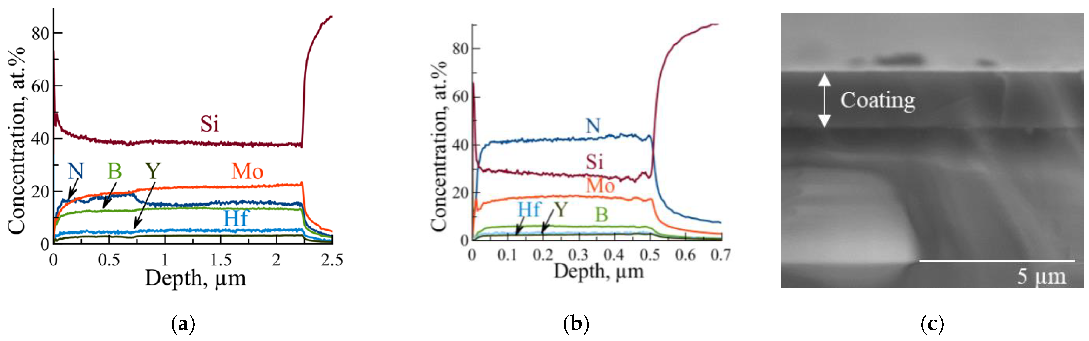
| 37.5 | 0 | 27.1 ± 1.0 | 45.8 ± 1.1 | 17.2 ± 0.2 | 4.1 ± 0.1 | 6.8 ± 0.3 | 0 | 2.7 | 270 |
| 25.0 | 12.5 | 22.7 ± 1.2 | 39.8 ± 0.5 | 13.7 ± 0.5 | 3.1 ± 0.2 | 5.3 ± 0.3 | 15.4 ± 1.2 | 2.5 | 250 |
| 12.5 | 25.0 | 17.7 ± 0.7 | 37.5 ± 0.6 | 7.4 ± 0.1 | 2.5 ± 0.1 | 3.5 ± 0.2 | 31.4 ± 0.9 | 2.0 | 200 |
| 0 | 37.5 | 17.4 ± 0.5 | 27.9 ± 0.9 | 5.8 ± 0.1 | 2.5 ± 0.1 | 3.2 ± 0.2 | 43.2 ± 0.8 | 0.5 | 50 |
Disclaimer/Publisher’s Note: The statements, opinions and data contained in all publications are solely those of the individual author(s) and contributor(s) and not of MDPI and/or the editor(s). MDPI and/or the editor(s) disclaim responsibility for any injury to people or property resulting from any ideas, methods, instructions or products referred to in the content. |
© 2023 by the authors. Licensee MDPI, Basel, Switzerland. This article is an open access article distributed under the terms and conditions of the Creative Commons Attribution (CC BY) license (https://creativecommons.org/licenses/by/4.0/).
Share and Cite
Kiryukhantsev-Korneev, P.; Sytchenko, A.; Chudarin, F.; Senatulin, B.; Levashov, E. The Influence of Nitrogen Flow Rate on the Structure and Properties of Mo-Hf-Y-Si-B-N Coatings. J. Compos. Sci. 2023, 7, 253. https://doi.org/10.3390/jcs7060253
Kiryukhantsev-Korneev P, Sytchenko A, Chudarin F, Senatulin B, Levashov E. The Influence of Nitrogen Flow Rate on the Structure and Properties of Mo-Hf-Y-Si-B-N Coatings. Journal of Composites Science. 2023; 7(6):253. https://doi.org/10.3390/jcs7060253
Chicago/Turabian StyleKiryukhantsev-Korneev, Philipp, Alina Sytchenko, Fedor Chudarin, Boris Senatulin, and Evgeny Levashov. 2023. "The Influence of Nitrogen Flow Rate on the Structure and Properties of Mo-Hf-Y-Si-B-N Coatings" Journal of Composites Science 7, no. 6: 253. https://doi.org/10.3390/jcs7060253