1. Introduction
The current industrial and technological development requires new manufacturing methods with high productivity, rapid prototyping and the ability to produce complex-shaped parts at a relatively low cost. Additive manufacturing (AM) is among the novel industrial technologies for fast prototyping of the complex parts made from different materials [
1,
2,
3]. All modern AM methods are based on a layer-by-layer melting and solidification of the feedstock material (wire or powder) using different sources of energy (laser, plasma, electric arc, or electron beam). Selective laser melting/sintering, electron beam and arc additive manufacturing are the mostly well-known AM methods. The wire–feed electron beam additive manufacturing (EBAM) has some advantages over the powder-bed laser-based AM methods: high deposition rates and the ability to produce large components. However, the as-built EBAM-fabricated parts often require post-built machining and heat treatments to achieve a desired quality [
1,
2,
3].
Conventionally produced austenitic stainless steels of the 300-series have good weldability and high corrosion resistance, being widely used in industrial, infrastructural and medical applications [
4,
5,
6]. Austenitic stainless steel is a material appropriate for the EBAM process. Unfortunately, the elemental and phase compositions of the as-built parts do not coincide with those in steel wire used in the EBAM process. Typical elemental composition of austenitic stainless steels includes about 9% of nickel for stabilization of the austenitic structure [
4]. At the expense of the high heat input, depletion of a melting pool with nickel occurs during the EBAM process, and, independently from the processing parameters, EBAM-fabricated parts always contain the residual
δ-ferrite. Therefore, the main reason for
δ-ferrite formation is the EBAM-assisted variation of a Cr/Ni equivalent of steel and, consequently, the change in solidification mode [
7,
8,
9,
10]. Additionally, columnar coarse austenitic grains usually grow during the additive manufacturing and provide the high anisotropy of the mechanical properties in the as-built material [
8,
9,
10]. An anisotropic two-phase (
γ-austenite +
δ-ferrite) microstructure is formed due to the nonequilibrium solidification and crystallization conditions during layer-by-layer deposition of the material and complex thermal history of the resulting bulk product [
8,
9,
10,
11,
12]. Post-production heat treatment of the additively fabricated stainless steel partially eliminates these effects, i.e, reduces the fraction of
δ-ferrite but does not completely dissolve it and retains grain size unaffected [
8,
9,
11]. In fact, EBAM-fabricated bulk products made from stainless steels type AISI304 or AISI321 possess dual-phase composite structures because the content of
δ-ferrite in them could be as high as 20% [
8,
9,
10].
High fraction of dendritic or globular “hard”
δ-phase, which is randomly distributed in “soft” austenitic matrix, can influence all microstructure-dependent mechanical properties, stages of plastic flow, deformation mechanisms, and fracture of the additively manufactured steels. Metastable austenitic steels typically undergo a strain-induced
γ→α′ or
γ→ɛ→α′ martensitic transformation (MT) [
13,
14]. Kinetics and the resulting volume fraction of the strain-induced martensite (SIM) are determined by the chemical composition and structure of steel (stacking fault energy (SFE), grain size, phase composition, etc.) and deformation regime (strain rate, temperature, deformation mode, etc.) [
13,
14,
15,
16,
17,
18,
19,
20]. In austenitic stainless steels (Fe–18%Cr-(8–14)%Ni, mass.%) with low SFE (below 20 mJ/m
2), the strain-induced
γ→ɛ→α′ MT is realized at
T < 300 K [
14,
15,
17,
18,
19,
20]. The nucleation and growth of the
α′-martensitic phase can be realized both with or without intermediate twinning or ε-martensite [
15,
21,
22]. The amount of the
α′-SIM in the samples is a temperature-dependent characteristic: if the deformation temperature decreases, the kinetics of the
γ→α′,
γ→ɛ→α′ MTs speed up, which assists with a higher strain-hardening rate and higher tensile strength [
14,
18,
19,
20,
23]. The mechanisms of the MT development in austenitic stainless steels obtained using the conventional methods have been studied in detail, including the influence of the deformation temperature on tensile properties and the deformation behavior of such steels [
13,
14,
15,
16,
17,
18,
19,
20,
21,
22,
23].
Since austenitic steels obtained through additive manufacturing are promising materials for operation at low temperatures, the characteristics of the MTs in such materials are of special interest but they have not been studied yet. Y. Hong and coauthors [
24] have shown that high density of low-angle boundaries and cellular microstructure suppress dislocation slip and deformation twinning in austenitic stainless steel (fabricated by selective laser melting, SLM). Both factors reduce the number of nucleation sites for SIM, therefore enhancing austenite stability against MTs. Unlike the EBAM method, the
δ-phase does not arise in the SLM-produced austenitic stainless steels. To date, the effect of the
δ-ferrite on the characteristics of strain-induced martensitic transformation in EBAM-fabricated steels has not been revealed.
In this paper, we study the temperature dependence of the strength properties and SIM-assisted deformation behavior in stainless steel samples obtained using the EBAM method.
2. Materials and Methods
Steel billets with the linear dimensions of 110 × 33 × 6 mm3 were produced using the EBAM method (ISPMS SB RAS, Tomsk, Russia). Stainless-steel wire type AISI 321 with a diameter of 1 mm was used as a feedstock material. A carbon steel plate with the dimensions of 140 × 75 × 10 mm3 was used as a substrate, which was not cooled during the EBAM process. The additive manufacturing process was carried out in a vacuum chamber, and the following parameters were used: accelerating voltage—30 kV; beam current—40–50 mA; wire–feed speed—180 mm/min; beam sweep—4.5 × 4.5 mm2; scanning frequency—1 kHz. The samples were studied (1) after the additive manufacturing (AM) and (2) after the post-built solid–solution treatment that consisted of annealing for 1 h at a temperature of 1100 °C and water quenching (AM + SST). For comparative analysis, the conventionally produced steel samples type AISI 321 were used (solution-treated for the similar regime, hereinafter called “as-cast”).
Mechanical tests for the uniaxial static tension were carried out using flat proportional dumbbell-shaped samples with the gauge sections of 12 × 2.6 × 1.3 mm3. Tensile axis of the samples coincided with a building direction of the EBAM-fabricated billet. After mechanical grinding of the samples, an electrolytic polishing was carried out in a supersaturated solution of chromium anhydride CrO3 in orthophosphoric acid. Due to the different compositions of austenitic and ferritic phases, the ferritic one was etched during the polishing of the specimens. After that, it can be clearly identified with either light or scanning electron microscopy.
Tension was carried out at temperatures of 77, 183, 223, 273 and 300 K and an initial strain rate of 5 × 10⁻⁴ s–1 using an electromechanical testing system (model 1185, Instron, High Wycombe, GB) with a low-temperature chamber. At least five samples of the AM and AM + SST steels were tested at each temperature. As no extensometer could be used in the low-temperature chamber, the force (P) and the displacement of the traverse (Δl = l − l0, where l is the length of the deformed sample, and l0 is the initial length of the sample) were collected during the tensile tests. These parameters were converted to the engineering stress (σe = P/S0, S0 is the initial cross-sectional area of the sample) and engineering strain (εe = Δl/l0). Then, true stress (σt = σe (1 + εe))–true strain (εe = ln(l/l0)) plots were reconstructed assuming a uniform deformation of the sample at strains lower than what corresponded to an ultimate tensile stress (UTS). For higher strain, true diagrams could not be rearranged because the plastic deformation was localized in the neck. To ensure that samples deform uniformly before UTS is reached, some tensile tests were interrupted at different strains and visual control of the sample shape was carried out. Necks formed at the latter stages of plastic flow, after the UTS was reached. Using true diagrams, a strain-hardening rate, SHR = dσt/dεt, was calculated.
The microstructure of the samples was studied using scanning electron microscopy (SEM, Zeiss Leo Evo 50 (Zeiss, Oberkochen, Germany) with a supply for energy dispersive X-ray spectroscopy, EDS, accelerating voltage—30 kV, SE (secondary electrons) regime). Using SEM images, the sizes of austenitic grains and the widths of δ-ferrite lamellae were measured using a linear interception method. X-ray structural and phase analysis of the samples were carried out on a DRON-7 diffractometer (Bragg–Brentano geometry, Co-Ka radiation, accelerating voltage,15 kV, current, 15 mA, 2θ range, 40–120°, Bourevestnik, Saint Petersburg, Russia). The volume fraction of the magnetic δ-ferrite and α′-phase was determined using a multi-functional eddy current device MVP-2M (Kropus, Moscow, Russia) with a limit of the ferritic phase detection of 0.2%.
3. Results
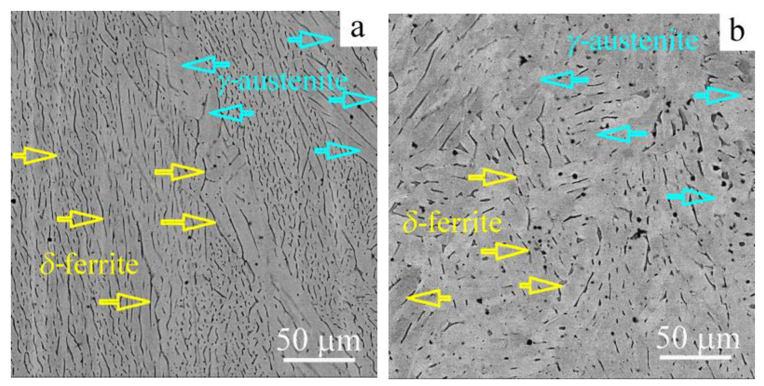
Figure 1 shows the characteristic SEM images of the microstructure in the AM and AM + SST samples. After AM, the microstructure of the samples consists of the coarse austenitic grains with colonies of dendritic
δ-ferrite, which are oriented mainly along elongated austenitic grains (this direction coincides with the building direction of the EBAM billet and tensile axis of the samples). While the transverse grain size of austenite is 100–500 microns, the longitudinal one could reach several millimeters. The volume fraction of
δ-phase is 14% as it was measured in the magnetic phase analysis. The thickness of the
δ-ferrite lamellae varies between 0.5 and 1.5 μm according to the SEM analysis (
Figure 1a).
Solid–solution treatment of the additively manufactured steel stimulates a
δ→γ phase transformation in the samples. Unfortunately, the complete dissolution of the
δ-ferrite does not occur, while the morphology of the
δ phase changes drastically. On SEM images, the globular, non-equiaxed
δ-ferrite lamellae are observed (
Figure 1b). After the solid–solution treatment, the volume content of the ferritic phase is 6%. At the same time, no visible changes were found in the grain structure of the austenitic phase, which is in accordance with our previous data [
8,
9].
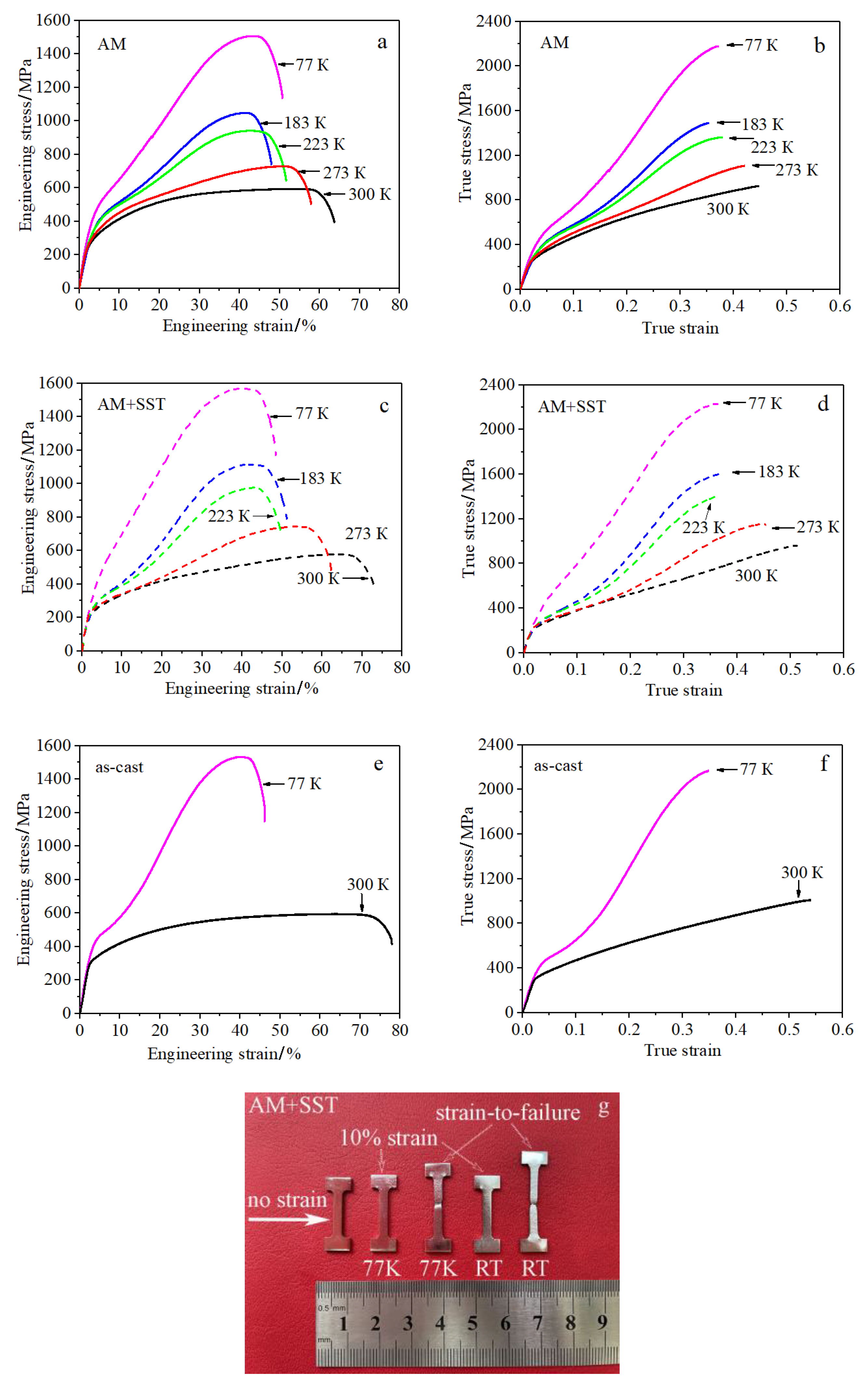
The tensile diagrams obtained for the AM and AM + SST samples depending on the test temperature are shown in
Figure 2. Engineering diagrams show the complete plastic flow of the material, including the stage of macroscopic strain localization (in the assumption of the invariable cross-section of the sample during straining). Maximum applied stresses on the engineering diagrams correspond to the UTS, and samples undergo uniform deformation at ε
e < ε
UTS. The common view of the non-deformed samples and those tensile-tested at room temperature and 77 K up to the 10% strain are shown in
Figure 2g. At strains higher than ε
UTS, plastic deformation is localized in a rather narrow region (necks are seen in
Figure 2g for the samples tensile tested to failure) both at room temperature and in a low-temperature deformation regime. The stage of the macroscopical localization of plastic flow in a pre-neck deformation regime is seen in every engineering diagram (
Figure 2a,c,e) but it has not been reconstructed in true stress–true strain diagrams (
Figure 2b,d,f) and has not been studied in this research.
At the assumption of the uniform decrease of the cross-sectional area of the samples, true stress–true strain diagrams show deformation behavior of the steels’ excluding stages at ε
t > ε
UTS (
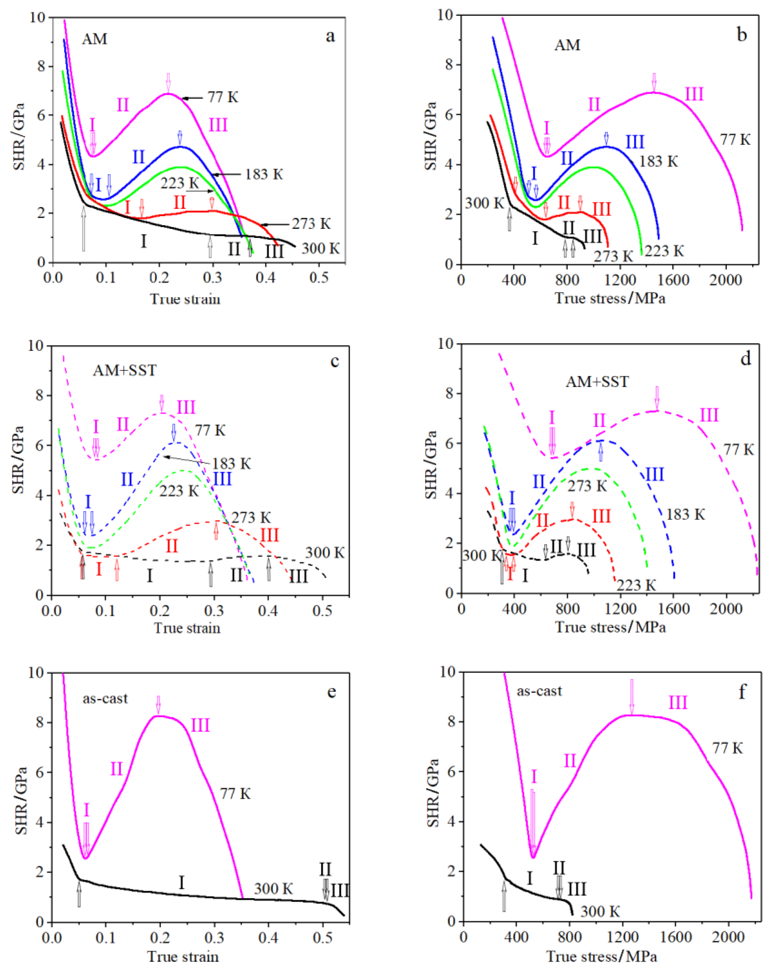
Figure 2b,d). At room temperature deformation, plastic flow of the AM and AM + SST samples develops in three main stages (
Figure 2b,d), which could be clearly identified by the strain-hardening rate (SHR = dσ/dε) variations with strain and stress (
Figure 3). After a rather long intermediate stage between elastic and the macroscopical plastic deformation of the samples, the stage I starts at stresses of about 400 MPa (0.05 true strain). The value of SHR gradually decreases with strain and stresses from 2 GPa at the beginning down to 1–1.5 GPa at the end of stage I (about 0.3 true strain). At higher strain, stage II starts, which is almost linear for the AM samples and shows insignificant growth of the SHR for the AM + SST samples. At strains higher than 0.4 (at true stress higher than 800 MPa), stage III starts. It is characterized by high SHR that gradually decreases with strain (stress) (
Figure 3a–c).
At room temperature, the strain-hardening behavior of AM + SST samples is very similar to that of the as-cast austenitic steel except for the differences in stage II: almost linear hardening is observed in the as-cast samples, and the increase in SHR with strain is typical of the AM + SST ones (
Figure 3c–f). Contrarily, the SHR values for the AM composite specimens are much higher than those in the as-cast steel in stage I, but the deformation behavior in stages II and III are very similar except for the length of the stages: the AM samples show lower elongation-to-failure and shorter lengths of the stages (
Figure 3a,b,e,f).
A decrease in test temperature is accompanied by a change in the shape of the flow curve for all samples. During tensile deformation of the AM and AM + SST samples at 273 K, stage I is much shorter (strain hardening is similar) and stages II and III start much earlier than those at room temperature deformation (
Figure 3a–d). Regardless of the phase composition of the samples, a pronounced increase in flow stresses with strain (stress) is observed in stage II, and the SHR value at this stage increases in comparison with that at room temperature. Again, the increase in SHR with strain and stresses in stage II is more pronounced for AM + SST-samples (
Figure 3a–d).
When the test temperature is lowered to 223 K, 183 K, and 77 K, stage I becomes very short, and stage II starts very close to the beginning of the plastic flow. Flow stresses and SHR values at stage II increase drastically with strain. Tensile diagrams take a pronounced S-shape (
Figure 2a–d). The slopes of the dependences SHR(ε) and SHR(σ) in stage II are greater for the AM + SST samples in comparison with the AM samples, in which the fraction of δ-ferrite is the highest (
Figure 3a–d). If one compares the stages of plastic flow at 77 K for the as-cast and additively fabricated materials, two main distinctions can be highlighted. First, despite the close strains at which stage II starts, the corresponded stresses and strain-hardening rate values are much lower in the as-cast material. Second, strain hardening increments ΔSHR/Δε and ΔSHR/Δσ in stage II are much higher for pure austenitic steel (
Figure 2 and
Figure 3).
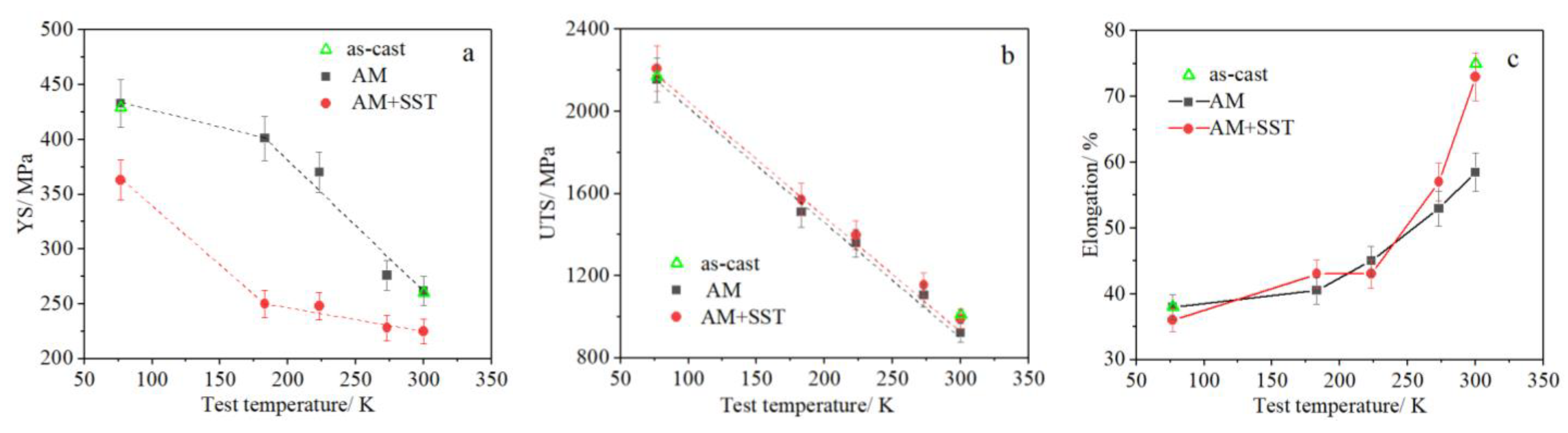
Figure 4 shows the temperature dependence of the yield strength (YS), the UTS and the elongation-to-failure for all steel samples. A decrease in test temperature is accompanied by an increase in the values of the YS and the UTS and by a decrease in total elongation of the steels in the temperature range (77–300) K. When comparing the values of the yield strength for the AM and the AM + SST samples, one can notice that with the decrease in the fraction of δ-ferrite in the microstructure, the YS decreases in the whole temperature range (
Figure 4a). Simultaneously, the UTSs for these specimens are equal and the total elongations are different only at room temperature deformation (
Figure 4b,c). The non-obvious result is that the YSs for as-cast materials (pure austenite) coincide with those for the composite AM samples containing 14% of δ-ferrite (
Figure 4a).
4. Discussion
The experimental data described above indicate that the content of
δ-ferrite affects the yield strength of the studied samples. It is surprising that the YSs of the pure austenitic as-cast samples and dual-phase AM samples are equal at temperatures of 77 K and 300 K. The grain sizes (
d) of these two materials are different (15μm for as-cast samples and hundreds of micrometers for AM samples). According to the well-known Hall–Petch relationship (YS~
KH-P ×
d−1/2,
KH-P is a constant ≈ 400 MPa × μm
1/2 [
25]), the YS of the coarse-grained AM samples must be much lower than that of the as-cast material in the whole temperature range (the decrease in grain size from 100–500 μm down to 15 μm is accompanied by a growth of the YS in 65–85 MPa). If one assumes the grain size of austenitic phase in the AM material, this idea is not supported by the data in
Figure 4a.
In fact, due to the high volume fraction of
δ-phase and its dendritic morphology, the plastic deformation of the AM samples should be considered as that for the composite material: “hard” inclusions of
δ-phase in “soft” austenitic matrix. When we estimate the YS of the AM samples, it is correct to use a ”rule-of-mixtures” [
26]: YS
γ+δ = 0.86 × YS
γ-phase + 0.14 × YS
δ-phase. This rule is generally applied for the aligned fiber reinforced metal matrix composite under a load in the direction of the fibers (
δ-ferrite primary arms in our case). In our previous paper [
9], we have considered that, in the very beginning of plastic flow of the AM samples, a free pass of dislocation glide is restricted by the γ/δ interphase boundaries. Therefore, the mean distance between ferritic lamellae could be assumed as
d in the Hall–Petch relationship for the resultant value YS
γ-phase. This assumption allowed us to describe the experimentally observed decrease in the YS value in the AM + SST samples (
Figure 4a) due to the partial dissolution of δ-ferrite arms during the SST and due to the increase in a mean-free pass for the dislocation glide. In this approach, the YS
γ+δ of the AM samples would exceed the YS of the as-cast material because: (1) the mean distance between ferritic lamellae is one order value lower than the grain size of austenite in the as-cast samples (
Figure 1a), and the term 0.86 × YS
γ-phase for the AM sample could be higher than the YS
γ-phase for the as-cast material; (2) the additional term 0.14 × YS
δ-phase would increase the YS
γ+δ value. This difference is compensated by the δ-ferrite-assisted change in the local stress state in a bulk of the materials. Due to the different elastic properties of the austenite and ferrite, the “hard” δ-ferrite lamellae play the role of stress concentrators under external loading [
26,
27,
28,
29] and can initiate a macroplastic flow at stresses, which are lower than the YS
γ+δ calculated using the ”rule of mixtures”. This question is still open and needs a precise calculation of the YS in the framework of a separate paper. Nevertheless, the above discussion is supported by the temperature dependences of the YS for the AM and AM + SST samples. The dependence YS(
T) for the AM + SST material in
Figure 4a has a view typical of fcc materials: the substantial growth of the YS at
T < 200 K in a temperature range of a thermally activated dislocation glide and a plateau at
T > 200 K [
30]. For the AM samples with high fraction of the δ-ferrite, the slope ΔYS/Δ
T decreases in a low-temperature deformation regime. This is because the temperature dependence of the YS for bcc ferrite is much higher than that for the fcc austenite [
31]. Therefore, in the lower test temperature, the stronger δ-phase reduces the YS
γ+δ of the composite material.
The γ/δ interphase boundaries act as barriers for dislocations, and “hard” inclusions of δ-ferrite change stress distribution in the bulk of material, making it very inhomogeneous during tensile testing. As a result, δ-ferrite can assist the activation of dislocation sources in a primary slip system and those with non-maximum Schmid factors (secondary slip systems), enhance the multiple slip and promote the accumulation of dislocations in the interdendritic austenite. We confirmed the similar effects using transmission electron microscopical studies of a high-nitrogen steel and the multicomponent alloys with the coarse “hard” particles [
29,
32]. The stress-assisted multiple slip promotes high strain hardening in stage I for the AM and the AM + SST samples as compared to single-phase as-cast material (
Figure 2 and
Figure 3).
The transition to the stage II is associated with the activation of strain-induced (
γ→α′) and (
γ→ɛ→α′) martensitic transformations in austenitic CrNi stainless steels with low SFE [
13,
15,
18,
19,
20].
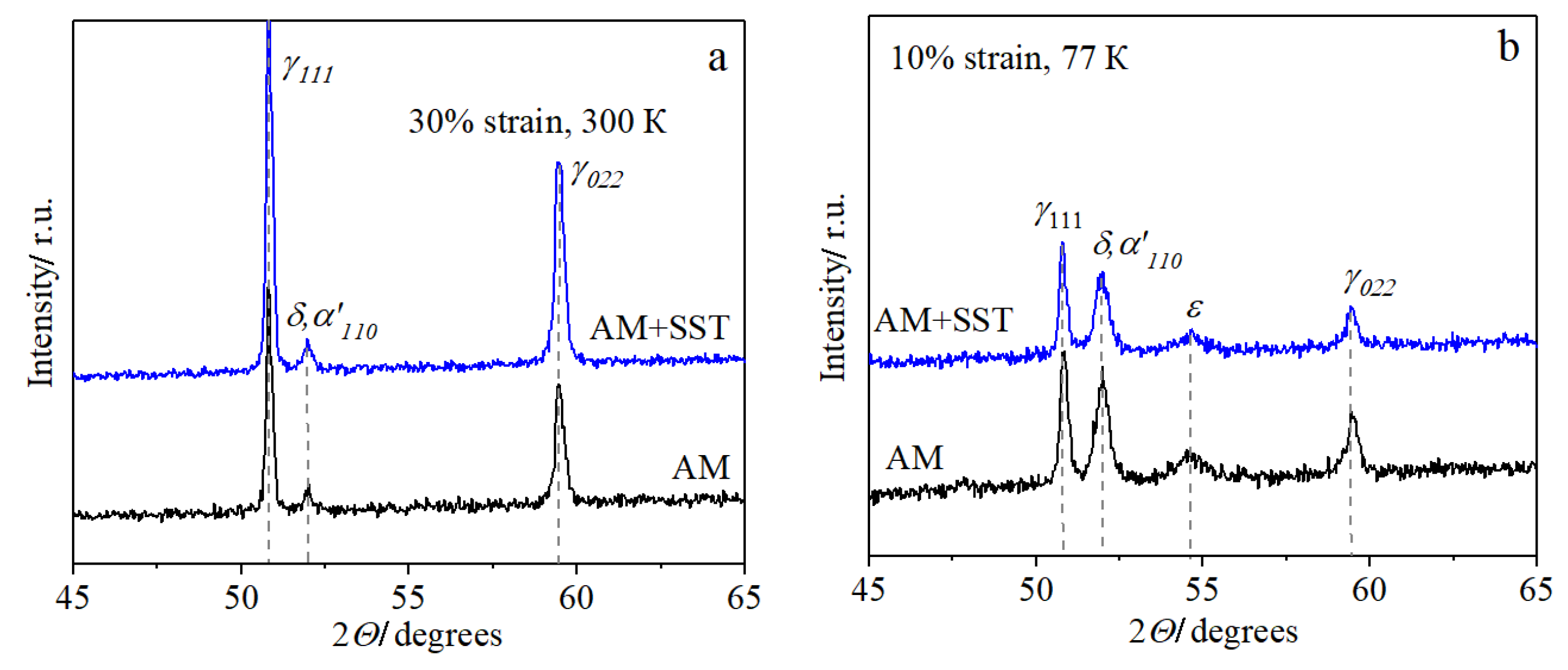
Figure 5 shows the X-ray diffraction patterns obtained for the AM and AM + SST samples tensile-tested at room temperature and at 77 K to the strains, corresponding with the beginning of stage II. After room temperature deformation up to 30% strain, austenite is the main phase in the AM and AM + SST specimens, but weak (
δ + α′) reflections are seen in the diffraction patterns (both
δ and
α′ phases possess a bcc crystal lattice and close lattice parameters; therefore they cannot be separated in X-ray diffraction patterns;
Figure 5a). The only
α′ phase could arise during the deformation, while fraction of δ-ferrite does not vary. Therefore, the insignificant fraction of SIM was formed at room temperature deformation in stage I. The weak reflections of the ε-phase and relatively high lines of
α′-martensite are clearly seen in
Figure 5b. This proves the (
γ→ɛ→α′) sequence of the transformation at 77 K. The growth of the
α′-martensitic phase could be realized either with or without intermediate ε-martensite, and the temperature dependence of the strain-induced transformation sequence is in accordance with [
15,
18,
21,
22].
The macroscopical (
γ→α′) transformation is realized in stage II. The strain-hardening rate at stage II is typically directly proportional to the fraction of SIM [
19,
20]. Deformation behavior of the samples does not allow one to compare the difference in the (
γ→α′) transformation at room temperature due to the slow transformation kinetics. However, for low-temperature deformation regimes, the analysis of the deformation stage II in
Figure 3 and
Table 1 shows that:
- (i)
The composite dual-phase steels (AM and AM + SST samples) possess slower kinetics of the strain-induced (γ→ɛ→α′) martensitic transformation relative to the single-phase austenitic as-cast material. Additionally, the higher the fraction of δ-phase in samples, the slower the SIM kinetics;
- (ii)
δ-ferrite fraction weakly influences strain for the start and length of stage II, which corresponds to the macroscopic growth of the α′ SIM. In the dual-phase steels, stage II starts mostly at higher stresses and SHRs compared to pure austenitic as-cast steel. Therefore, the start of the transformation needs higher stresses and strain hardening for the composite structure than for pure austenite.
These results directly show that dendritic lamellae and globular coarse particles of δ-ferrite partially suppress the strain-induced martensitic transformation in stainless steel type 321. These data are in accordance with the results reported by Y. Hong [
24], who obtained similar SIM behavior for the SLM-fabricated austenitic stainless steel. The authors concluded that low-angle grain boundaries and cellular microstructure inhibit dislocation slip, the formation of dislocation bands and twins. All these factors restrict the nucleation of
α′ SIM. In our case, the reason for the reduced kinetics of the SIM transformation in the EBAM-fabricated samples could be similar: a δ-ferrite-assisted stress distribution stimulates dislocation gliding in the multiple slip systems in the stage I, providing a specific highly defective microstructure in interdendritic regions and inhibiting
α′ nucleation and growth.
5. Conclusions
For the first time, strength properties, deformation behavior, and development of the strain-induced γ→α′ and γ→ɛ→α′ MT in samples of stainless steel, fabricated using electron beam additive manufacturing, have been explored in a wide temperature range. The uniaxial tensile testing at the temperatures of 77, 183, 223, 273 and 300 K has been carried out for two types of the samples: after additive manufacturing process (as-built) and after post-processing solid solution treatment. The samples have the dual-phase (γ + δ) structures with different contents of δ-ferrite: 14% and 6%, respectively.
In the studied temperature range, the samples with higher content of δ-ferrite have higher values of yield strength. The composite dual-phase steels (AM and AM + SST samples) possess slower kinetics of strain-induced (γ→ɛ→α′) martensitic transformation in deformation stage II relative to the single-phase austenitic as-cast material. A novel approach has been proposed for the interpretation of the results. The plastic deformation of the additively manufactured samples should be considered for the composite materials. The YS of the samples could be described by the ”rule of mixtures” assuming that “hard” δ-ferrite lamellae play the role of stress concentrators in a “soft” austenitic matrix, and they can reduce the yield strength and partially suppress strain-induced martensitic transformation in a composite structure under loading.

 ,
, 


