Article

Dissimilar Probeless Friction Stir Spot Welding of Aluminum Alloy and USIBOR®1500-AS Steel Thin Plates

by
Mariia Rashkovets
1,2,*,
Maria Emanuela Palmieri
1,
Nicola Contuzzi
1,*,
Luigi Tricarico
1 and
Giuseppe Casalino
1
1
Department of Mechanics, Mathematics and Management, Polytechnic University of Bari, Via Orabona, 4, 70124 Bari, Italy
2
World-Class Research Center “Advanced Digital Technologies”, State Marine Technical University, Lotsmanskaya Street, 3, 190121 St. Petersburg, Russia
*
Authors to whom correspondence should be addressed.
J. Manuf. Mater. Process. 2024, 8(2), 55; https://doi.org/10.3390/jmmp8020055
Submission received: 31 December 2023 / Revised: 1 February 2024 / Accepted: 1 March 2024 / Published: 4 March 2024
(This article belongs to the Special Issue Advanced Joining Processes and Techniques 2023)

Abstract

:
Lap joining of an aluminum AA6082-T6 plate and a UHSS steel plate coated with an Al-Si layer was performed using Probeless Friction Stir Spot Welding (P-FSSW). The dwell time and rotational speed were controlled in the range of 10–15 s and 1000–1500 rpm, respectively. For all the samples, thermo-mechanical deformation occurred solely within the upper AA6082 plate. A refined grain structure was formed in the aluminum plate close to the surface. The dwell time was responsible for the intensity of the material flow, resulting in stirring between the Al-Si layer and the aluminum plate at 15 s. The microhardness distribution corresponded to the microstructure features.

1. Introduction

In the automotive industry, engineers are constantly exploring new ways to promote environmental sustainability. Ultra-High-Strength Steels (UHSS), together with aluminum alloys, hold significant potential for a substantial reduction in the overall vehicle weight, thereby improving fuel efficiency and reducing emissions [1]. However, joining automotive components made of steel and aluminum using traditional fusion welding is known to be challenging due to the formation of intermetallic FexAly compounds (IMCs), porosity, cracking, and softening of the aluminum side [2,3,4,5]. Since the formation of IMCs is related to the chemical reaction and interdiffusion between Fe and Al, its thickness is largely determined by the temperature and duration of the welding process [6]. Therefore, it remains difficult to obtain a reliable joint in resistance spot welding (RSW), even with the use of special filler materials, due to the high temperature of the process [7]. Further, blanks made of UHSS are often coated with a protective aluminum–silicon (Al-Si) coating to prevent oxidization and decarburization during primary hot stamping. This coating mixes up in the weld pool and partially precipitates as intermetallic phases at the fusion line, weakening the final bead [8]. Therefore, a low heat input is strongly recommended for both dissimilar couples (Al-steel) and coated steel in particular.
Friction stir welding (FSW) and its single-point modification, Friction Stir Spot Welding (FSSW), offer an alternative to conventional fusion welding for joining dissimilar materials. By employing friction heat and plastic deformation between the workpiece and tool, where a classical tool consists of a cylindrical shoulder and probe (pin), these methods eliminate the drawbacks associated with the melting of materials [9]. The final microstructure after FSW or FSSW is presented in a stir zone (SZ) with a recrystallized grain structure, a thermo-mechanically effected zone (TMAZ) with deformed grains, and a heat-affected zone (HAZ) with limited heat exposure.
It is well known that tool wear is a crucial issue for any solid-state process [10]. Its impact has a significant effect on both the production cost and the quality of the joints. Numerical and experimental studies have shown that significant amount of tool wear in the FSSW process occurs closer to the probe tip [11]. Therefore, UHSS steel requires relatively harder and subsequently more expensive tools [12]. Furthermore, one of the main drawbacks of the FSSW process is the keyhole defect resulting from the probe retraction [9]. To repair the keyhole, researchers of Helmholtz-Zentrum Geesthacht have recently developed Refill Friction Stir Spot Welding (RFSSW) [13]. However, this process demands a complex machine with regular cleaning of the tool holder system [14]. Another cost-effective adoption of FSSW is Probeless Friction Stir Spot Welding (P-FSSW), where the primary distinction is the absence of a probe, with the subsequent elimination of keyhole defects and negligible tool wear [15,16].
While, in theory, solid-state welding based on friction effectively eliminates the challenges related to IMCs, numerous studies state that a thin FexAly IMC layer is still formed at the dissimilar interface [17]. Furthermore, an Al-Si coating may serve as a filler material to promote better interfacial bonding between the aluminum and steel [18,19,20]. For instance, da Silva et al. [18] reported the possibility of welding an AA1050 aluminum alloy and 22MnB5 steel using FSSW. Based on the results of tensile tests, the authors concluded that the Al-Si coating could play an important role in the weldability of these materials since it could positively enhance the diffusion ability of Al into the coating. However, no explanations regarding the behavior of this layer and the interaction between the plates during welding were presented. Ishak I. et al. [21] showed the feasibility of using a scroll grooved probeless tool to form quality joints between thin plates of galvanized steel and A6022-T4 aluminum. However, no studies on P-FSSW using flat tools for joining aluminum alloys and steel coated with an Al-Si layer have been published.
The present study aims to investigate lap welds of thin plates made of an AA6082-T6 aluminum alloy and Al-Si coated press hardened steel USIBOR®1500-AS using the Probeless Friction Stir Spot Welding (P-FSSW) process with a flat shoulder. The focus of the paper is to examine the influence of rotational speed and dwell time during P-FSSW on the resultant joint microstructure.

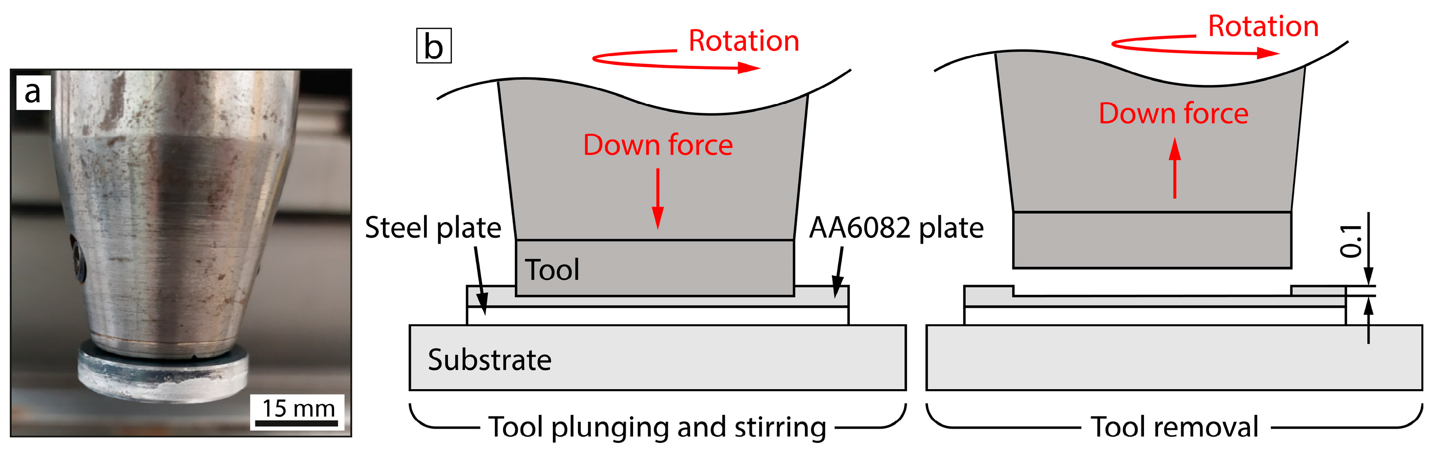
2. Materials and Methods

To fabricate dissimilar welds in a lap configuration, plates of an AA6082-T6 aluminum alloy with a 1.5 mm thickness and USIBOR®1500-AS steel with a 1.3 mm thickness were used in this study. The chemical compositions of the base materials are summarized in Table 1. The initial microstructure of the AA6082-T6 aluminum alloy contained equiaxed grains of the aluminum solid solution with an average grain size of 6.9 μm and typical coarse intermetallic phases (Figure 1a). The initial microstructure of the USIBOR®1500-AS steel was, under hot rolled conditions, a ferritic–pearlitic structure (Figure 1b). The initial hot dipped Al–Si coating consisted of a primary α-Al phase with an Al-Si eutectic (∼25 μm thick), followed by a transition intermetallic (IMC) layer of FexAlySiz (∼7 μm thick). Hence, the complete coating thickness measured about 32 μm.
Figure 2b schematically represents the P-FSSW steps. The diameter of the shoulder of the probeless tool made of H13 tool steel was 30 mm (Figure 2a) and was fixed with a tilt angle of 0 deg. to the workpiece. Force-control mode was used to perform the P-FSSW process. The down force was determined based on a prior experimental study and kept constant as 7350 N [22]. The process parameters are listed in Table 2.
A cross-section of the final microstructure of the joining interfaces was examined using optical microscopy. The polished surface after standard metallographic preparation was chemically etched with Keller’s reagent: 2.5 mL HNO3 + 1.5 mL HCl + 1 mL HF + 95 mL distilled water. Its microhardness was measured with a load of 980 mN, steps of 100 μm, and a 3 s loading time using Vickers testing. The resulted curves represent 10 measurements from each side taken perpendicular to the joining line at the center of the cross-section of the samples. Elemental map distribution was performed using a scanning electron microscope equipped with an energy-dispersive spectroscopy detector.
The commercial finite element analysis (FEA) software MSC Simufact Forming 2022 was used to simulate both the temperature fields and material flow during P-FSSW. The present software couples both thermal and mechanical computations for each time step of the simulation. The temperature field is calculated according to transient heat conduction and finite difference analysis, while incremental finite element analysis is employed for the material flow within the whole workpiece. The near-contact tolerance and a specific formula inform the thermal heat transfer [23]. Previous studies have shown an axisymmetric material flow [22]; therefore, 2D axisymmetric mode was utilized for the simulation in the present study. A mesh of the real-size geometry was built using an integral meshing tool. The elements’ hexahedral length of the edge was varied from 0.1 mm (workpiece) to 0.4 mm (backing plate) with subsequent refinement during the simulation. All the plates in the workpiece were simulated as deformable bodies, while the tool, blank holder, and substrate were set as rigid bodies. The press stroke depth was set to the same as the final depth of the tool’s penetration into the top plate during the real experiment. After a distinct dwell time, the tool was moved back to the starting position. The initial temperature was 20 °C in accordance with the real process. The material data was provided by the integrated material library of MSC Simufact Forming.

3. Results and Discission

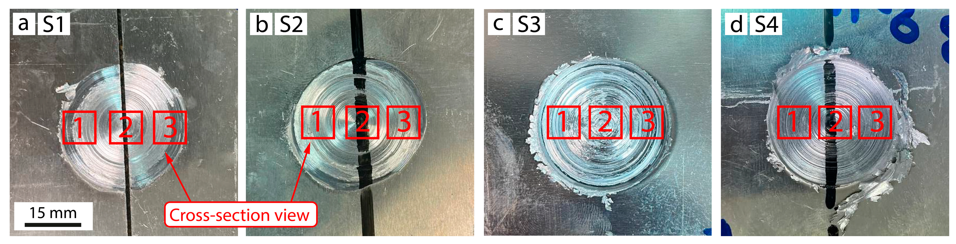
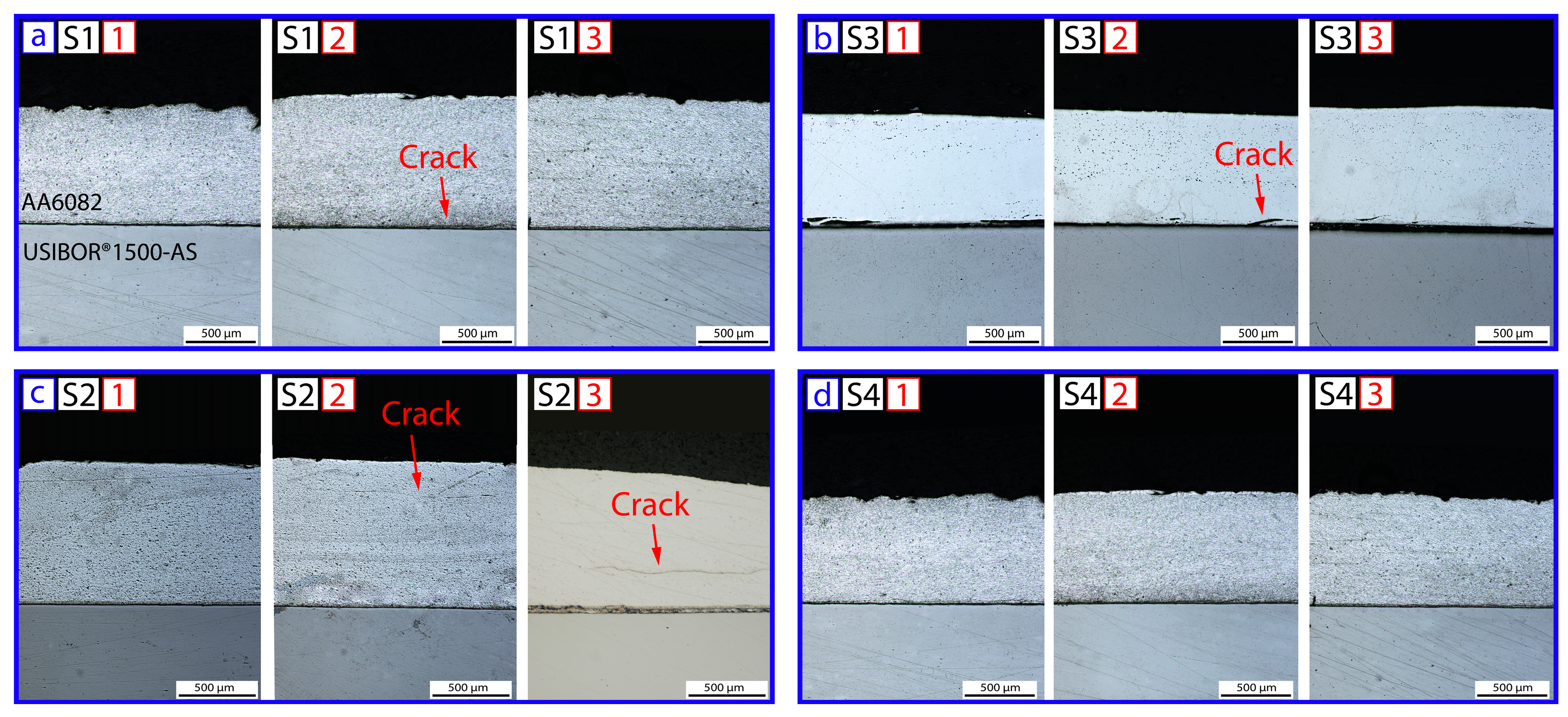
3.1. Weld Appearance and Macrostructure

Figure 3 depicts macro-images of the upper spot-welded surface. An increase in the rotational speed and dwell time resulted in a stronger indirect extrusion effect and a higher volume of burrs for the aluminum plate. (Figure 3c,d). Q. Chu et al. [24] also mentioned a significant increase in burr volume with an increasing dwell time and rotational speed due to an increasing intensity of material plasticization [25].
Figure 4 represents the joining cross-sections at the center and close to both sides of the outer diameter of the tool (red square in Figure 3). The joining interface was straight for all the samples, indicating that thermo-mechanical deformation occurred solely within the upper AA6082 plate. Cracks were formed in the upper AA6082 plate in both samples made with a rotational speed of 1000 rpm and in sample S3, obtained under the combination of 1500 rpm and a 10 s dwell time. The location of the cracks in relation to the dwell time was the following: the cracks found close to the joining interface corresponded to 10 s, while sample S2 made with a 15 s dwell time contained cracks in the upper and middle parts of the aluminum plate.

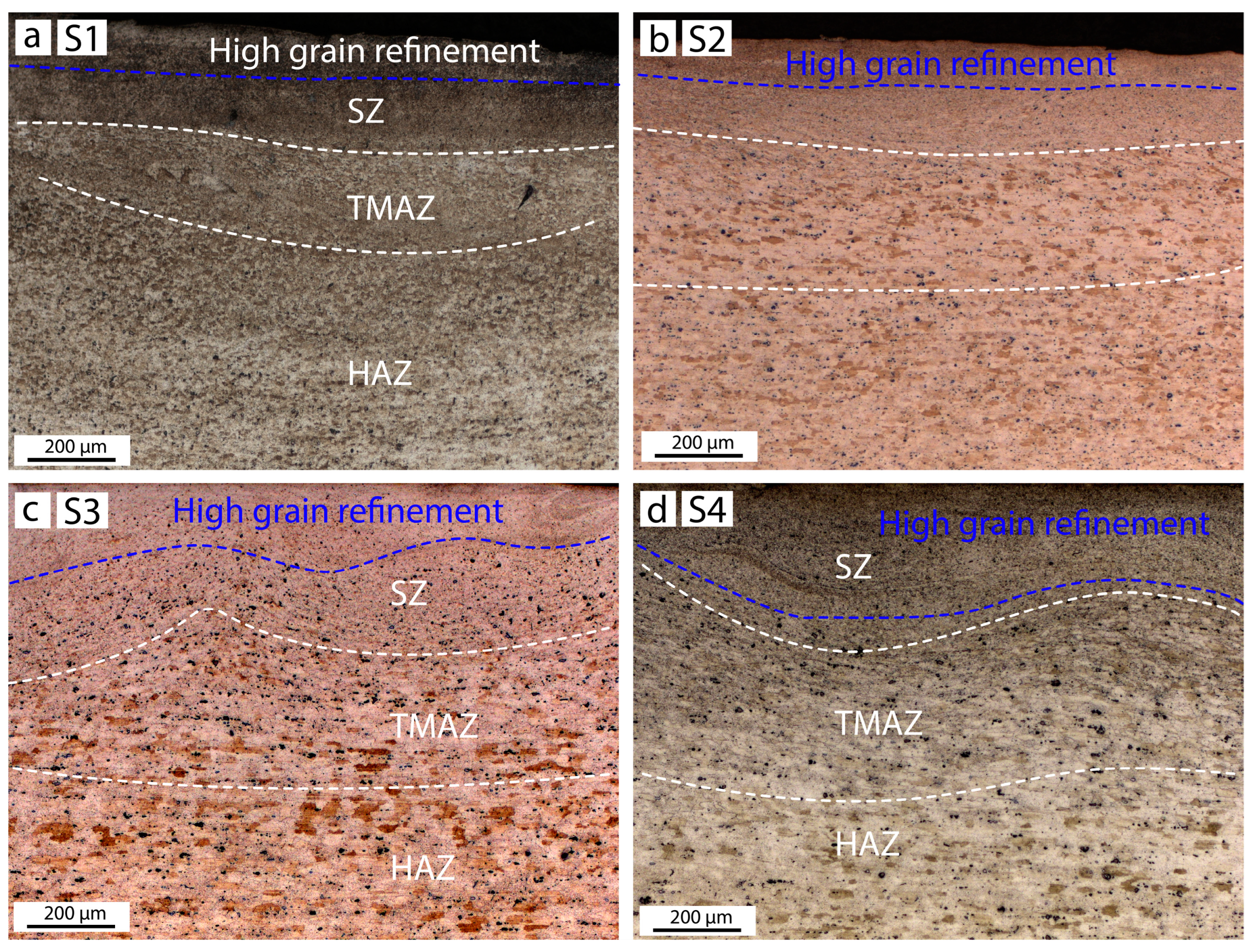
3.2. Microstructure of the Upper Plate

A previous study has shown that the material flow within the stir zone (SZ) of an aluminum plate is axisymmetric under all the parameters used [26]. Identical behavior was found in the present study. Figure 5 represents the microstructure of the upper AA6082 plate. None of the samples contained any vortexes. A thermo-mechanically affected zone (TMAZ) with slightly elongated grains typically formed next to the stir zone (SZ) of highly dispersed grains. It is evident that the heat input increased significantly in sample S4 (Figure 5d), which contained a more extensive material flow due to a combination of a longer dwell time of 15 s and a higher rotational speed of 1500 rpm compared to sample S1, made at 1000 rpm and 10 s (Figure 5a).
An increase in dwell time under a rotational speed of 1000 rpm has an effect on the extension of TMAZ due to provoking sustained material heating and plasticization (Figure 5a,b). In accordance with Reilly et al. [27], samples S3 and S4 initially had more plasticized material due to a higher rotational speed of 1500 rpm. Thus, an increase in the dwell time slightly enhanced the intensity of the material flow in the SZ due to sustained plasticization, while did not change the depth of TMAZ between samples S3 and S4. The intensity of the material flow in the SZ is characterized by a deeper area of highly refined grains (Figure 5c,d). This outcome also aligned with the formation and location of cracks, where sample S4 with the highest material flow does not contain visible cracks (see Figure 4).
T6 heat-treating condition, which describe the initial state of the aluminum plate, are characterized by coarse strengthening precipitates of β-Mg2Si. In the literature, there are many discussions regarding the phase changes during FSW/FSSW in 6XXX series. The results of transmission electron microscopy (TEM) indicate the dissolution of needle-like precipitation phases and reprecipitation of dispersed spherical GP-I in the SZ, while the TMAZ contains the coarser β-phase [28]. BSE SEM images of the present study also noted a significant decrease of precipitation phases in the fine-grained region of the SZ obtained in sample S4 (Figure 6a–d). Such variation probably indicated a linear relationship between the varying process parameters and heat input, where the combination of a high rotational speed and a longer dwell time resulted in an increase in heat input. However, this needs further investigation.

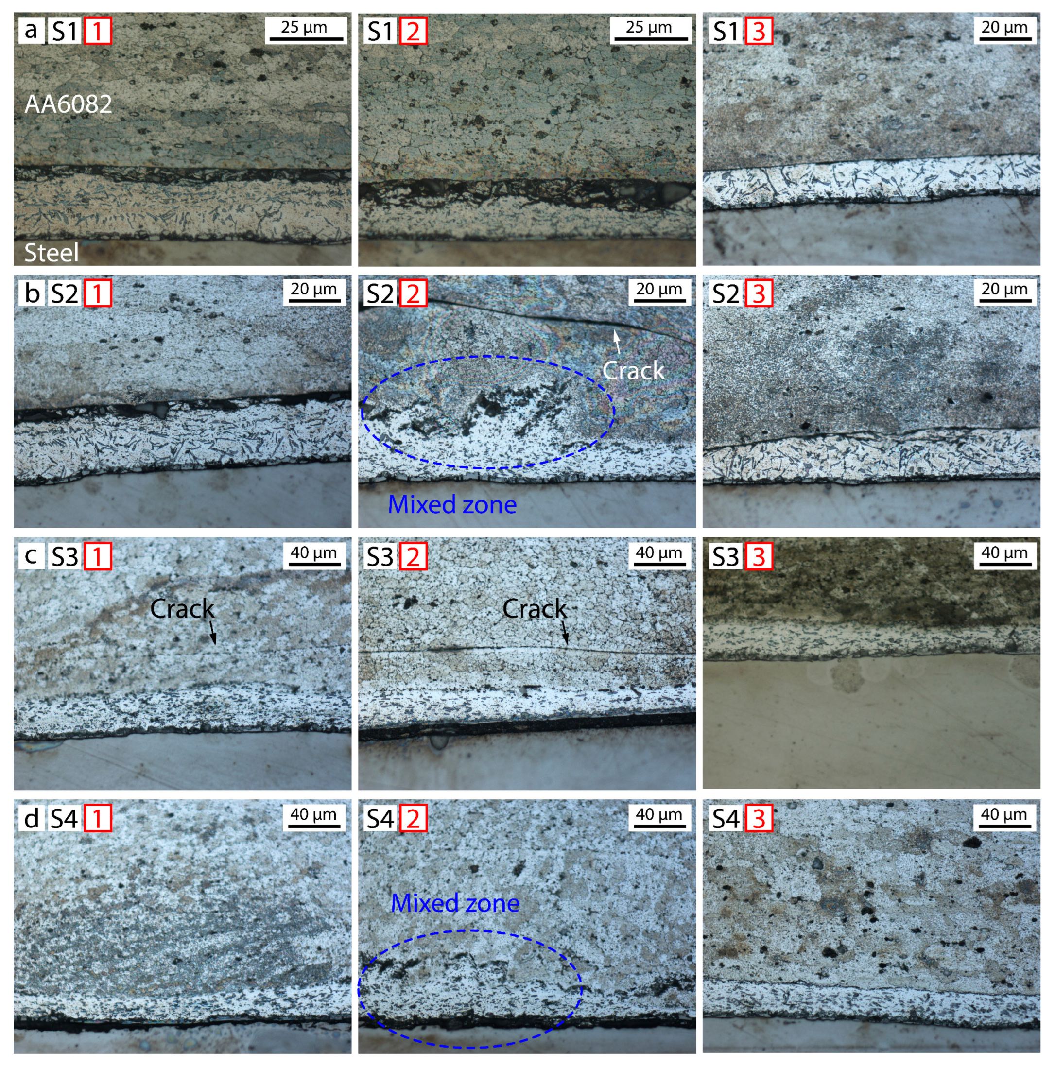
3.3. Microstructure of the Joining Interface
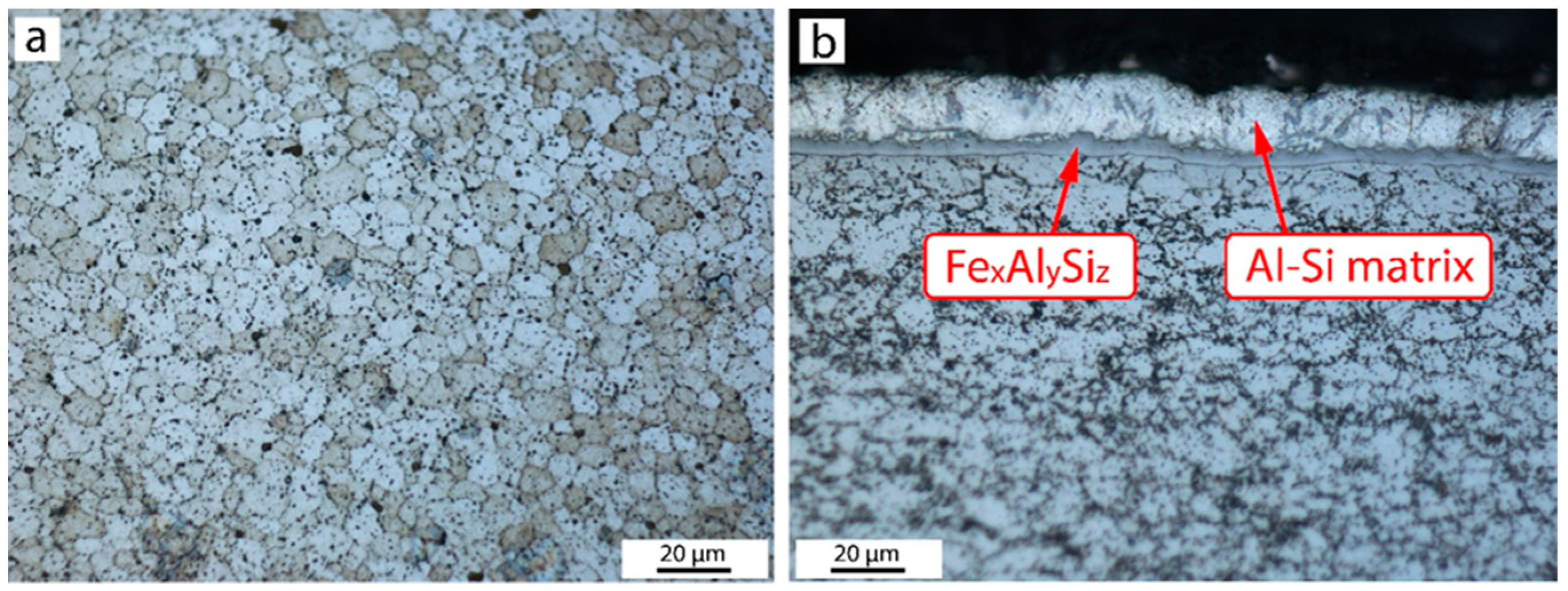
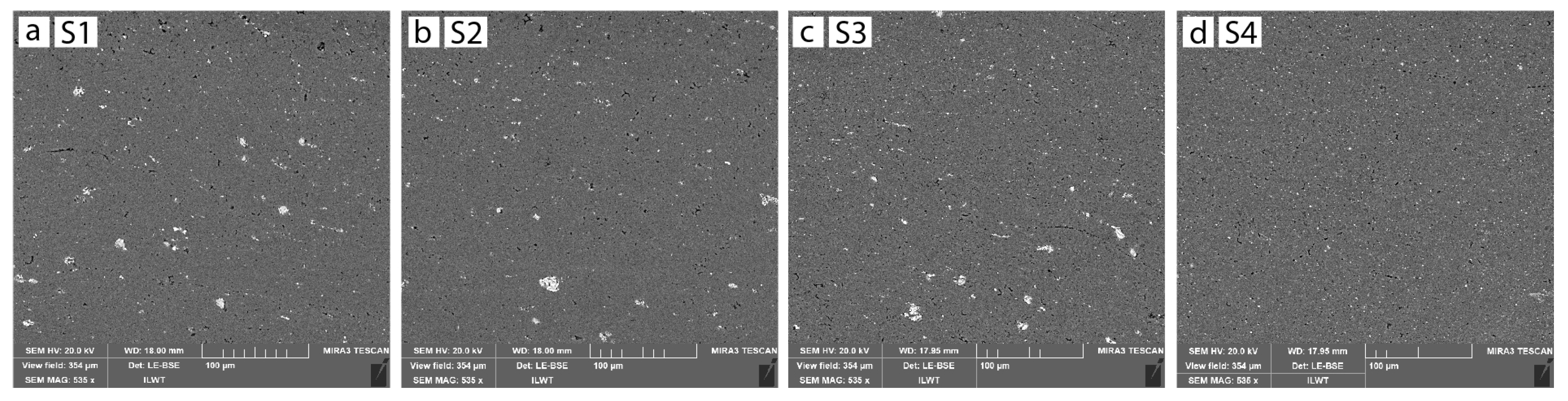
3.3.1. Al-Si Matrix

The detailed interfaces between the two plates over areas 1, 2, and 3 seen in Figure 4 are presented in Figure 6. The initial Al-Si eutectic structure was observed throughout the joining interface of all the samples without any cracks. The morphology of Al-Si layer remained constant across the whole shoulder diameter in samples S1 and S3 (Figure 7a,c), while it was stirring with the aluminum plate in samples S2 and S4 (Figure 7b,d).

3.3.2. Joining Interface between the Aluminum and the Al-Si Coating

It is well known that the surface oxides of aluminum alloy plates prevent atomic diffusion and adhesion between plates, thereby resulting in partial bonding [29]. These oxide films may be destroyed during plastic deformation [29]. Therefore, the interface between the AA6082 plate and Al-Si coating changed depending on the applied rotational speed and corresponding plastic deformation.
Samples S1 and S2 hardly displayed diffusion across the joining interface produced under 1000 rpm of rotational speed and both dwell time regimes due to insufficient heat generation. As a result, slight wear in the Al-Si coating was observed due to the retained surface oxides (Figure 7a,b). In contrast, a higher heat input and plastic deformation in samples S3 and S4 induced good bonding between the aluminum and Al-Si coating.

3.3.3. Interface between the Steel and the Al-Si Coating

Watanabe M. et al. [19] noted an increase in the IMC layer thickness with a longer dwell time for an interface of aluminum/low-carbon steel joined using FSSW. A lower heat input, formed according to a combination of both dwell time and 1000 rpm, kept the thickness of FexAlySiz in samples S1 and S2 at its initial state of 7 μm. The higher heat input in samples S3 and S4, achieved using 1500 rpm, promoted the growth of the IMC thickness by 3 μm. Therefore, the intensity of the solid diffusion, forming an IMC layer adjacent to the steel side, depended mainly on the rotational speed (Figure 8). It should be noted that the thickness of the FexAlySiz layer was rather larger at the center compared to the outer diameter of the tool. This probably is due to the heat generation during the dwell stage, when the highest local temperature was concentrated at the center of the spot weld due to the combined effects frictional heat and plastic deformation (upward material flow close to the center), both of which are influenced by the rotational shoulder.

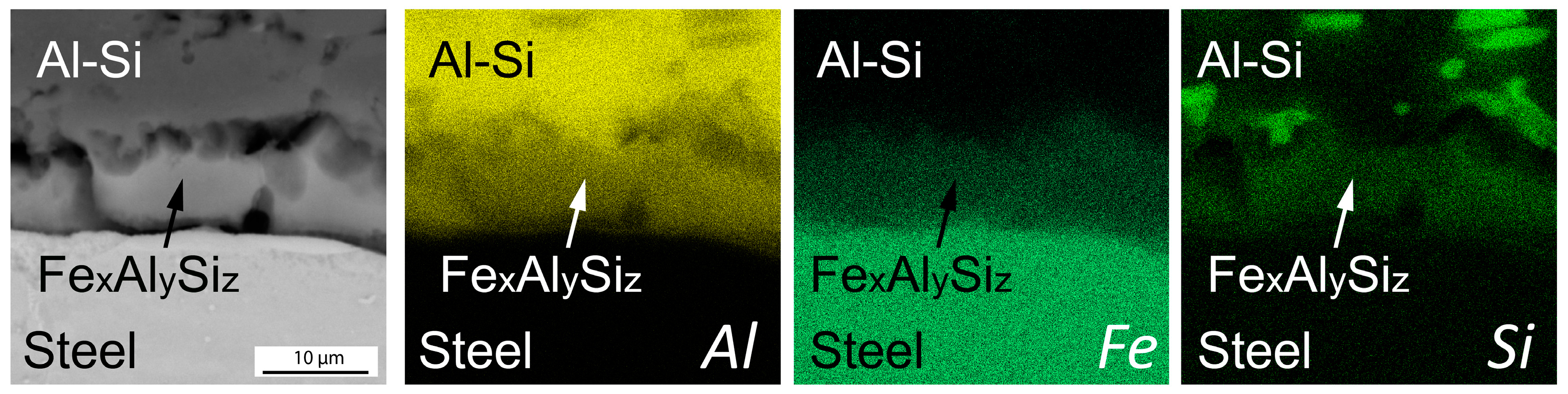
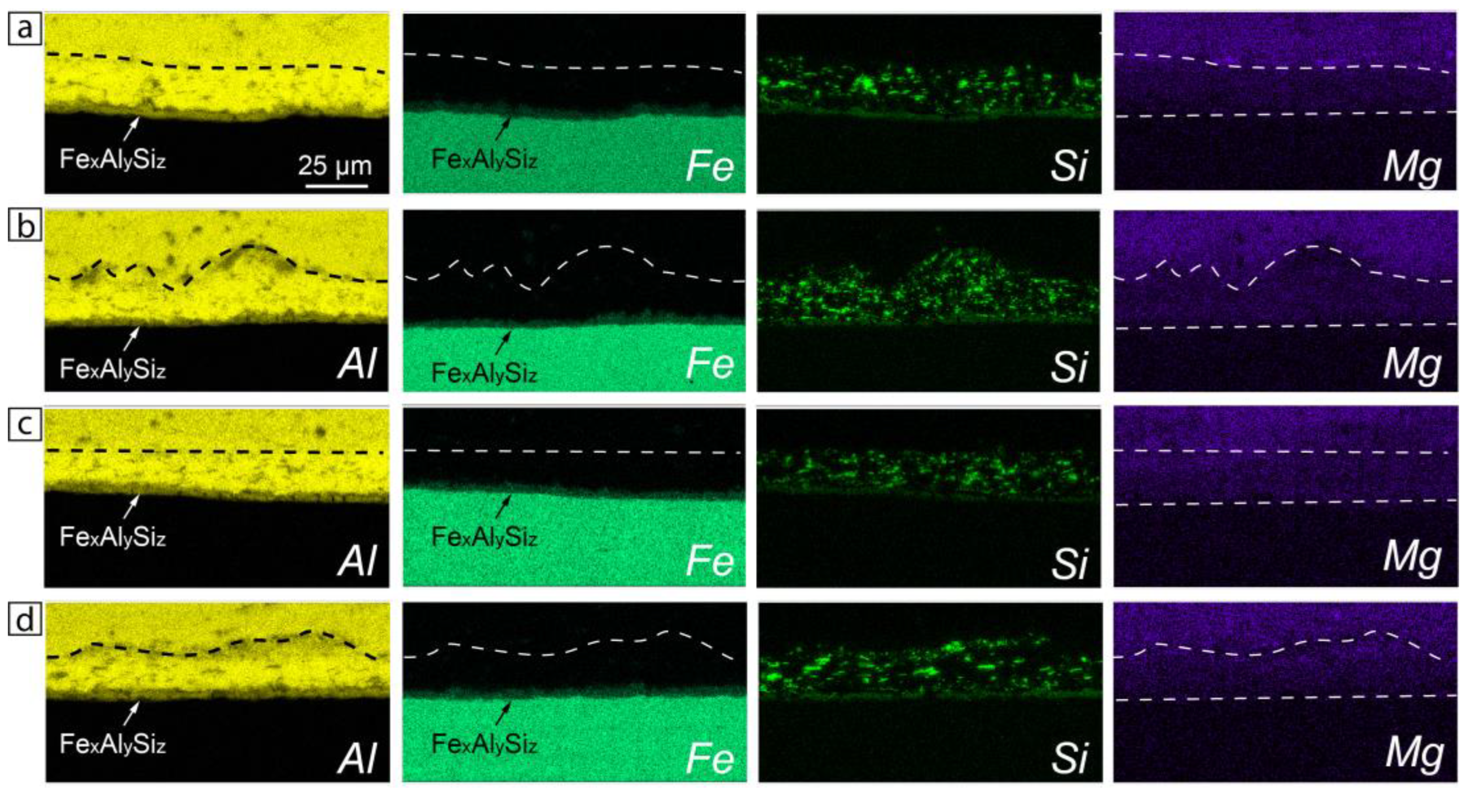
3.4. Elemental Distribution across the Joining Line

Figure 9 represents the distribution of the main elements such as Al, Fe, Si, and Mg. The elemental mapping clearly indicates regions enriched in Si, which are the needle-like particles of Al-Si eutectic, and the continuous layer of the initial FexAlySiz IMC phase at the interface between the coating and the steel. For all the samples, the distribution of Al and Fe was strongly correlated with the aluminum and steel plates, respectively, while the distribution of Mg, which belongs only to the aluminum plate, had differences. In Figure 9c,d, it is seen that samples S3 and S4 with a higher rotational speed experienced greater diffusion, resulting in a more uniform distribution of Mg through the joining line between the aluminum plate and coating. Such a Mg distribution also confirmed a higher heat input in the samples made under 1500 rpm.

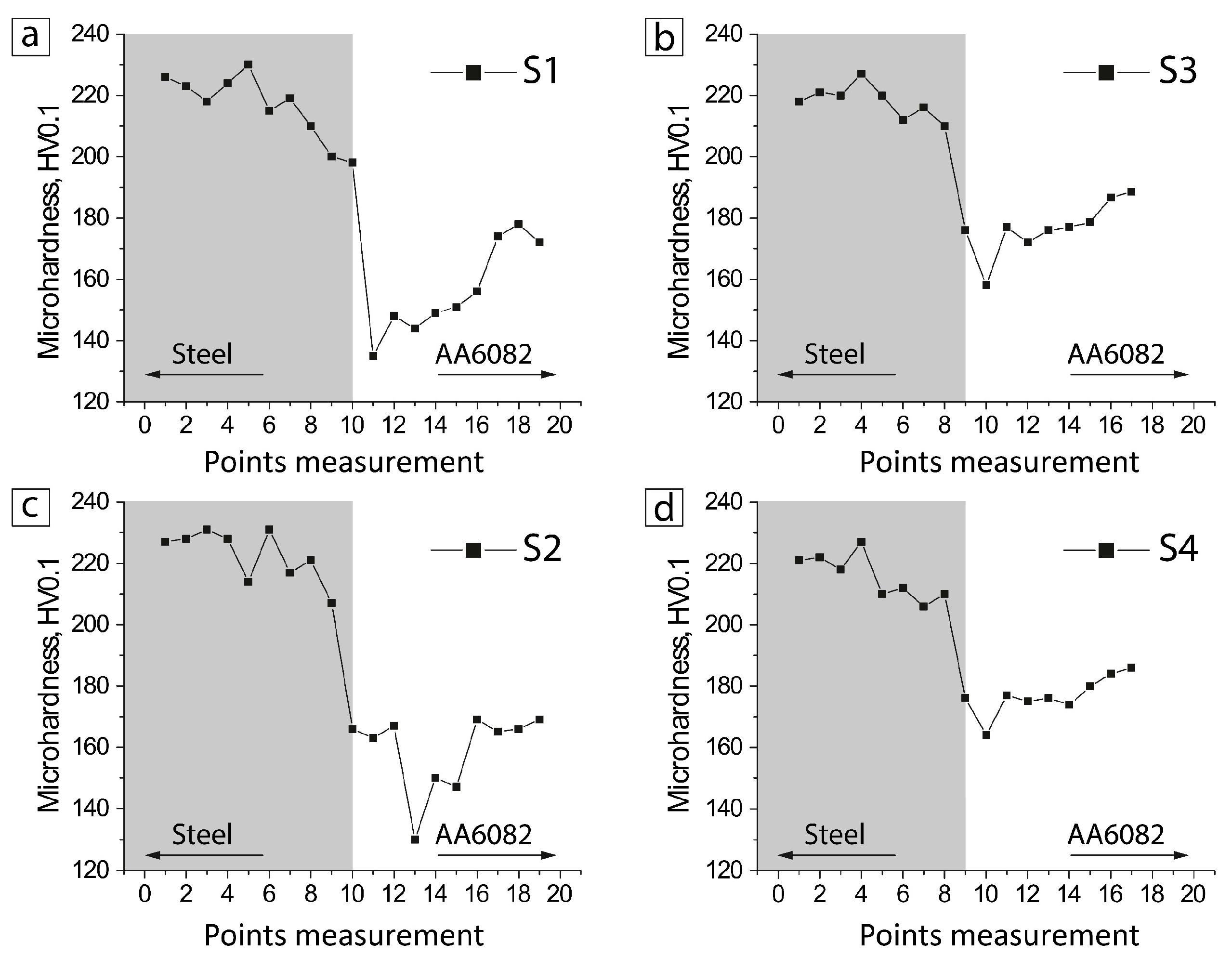
3.5. Microhardness of the Joining Interface

The microhardness distribution is presented in Figure 10. It is seen that the microhardness behavior essentially correlated with the microstructure features. A distinct similarity was presented between samples S1 and S2 and samples S3 and S4 obtained at 1000 rpm and 1500 rpm, respectively. Samples S1 and S2 exhibited an increase in the microhardness within the SZ, which was mainly attributed to the grain refinement (Figure 10a).
In contrast, samples S3 and S4 experienced an almost uniform microhardness distribution from the SZ to the joining line. Such behavior was attributed to the wider region of both the SZ and the TMAZ due to a higher heat input at 1500 rpm. Comparing samples S1 and S4, an increase in the microhardness of the TMAZ may be attributed to the higher plastic deformation of the grains (i.e., increased dislocation density).

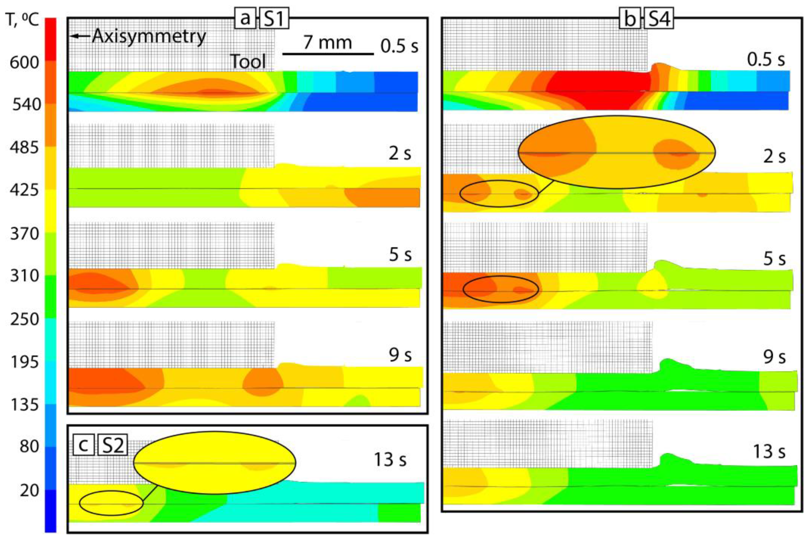
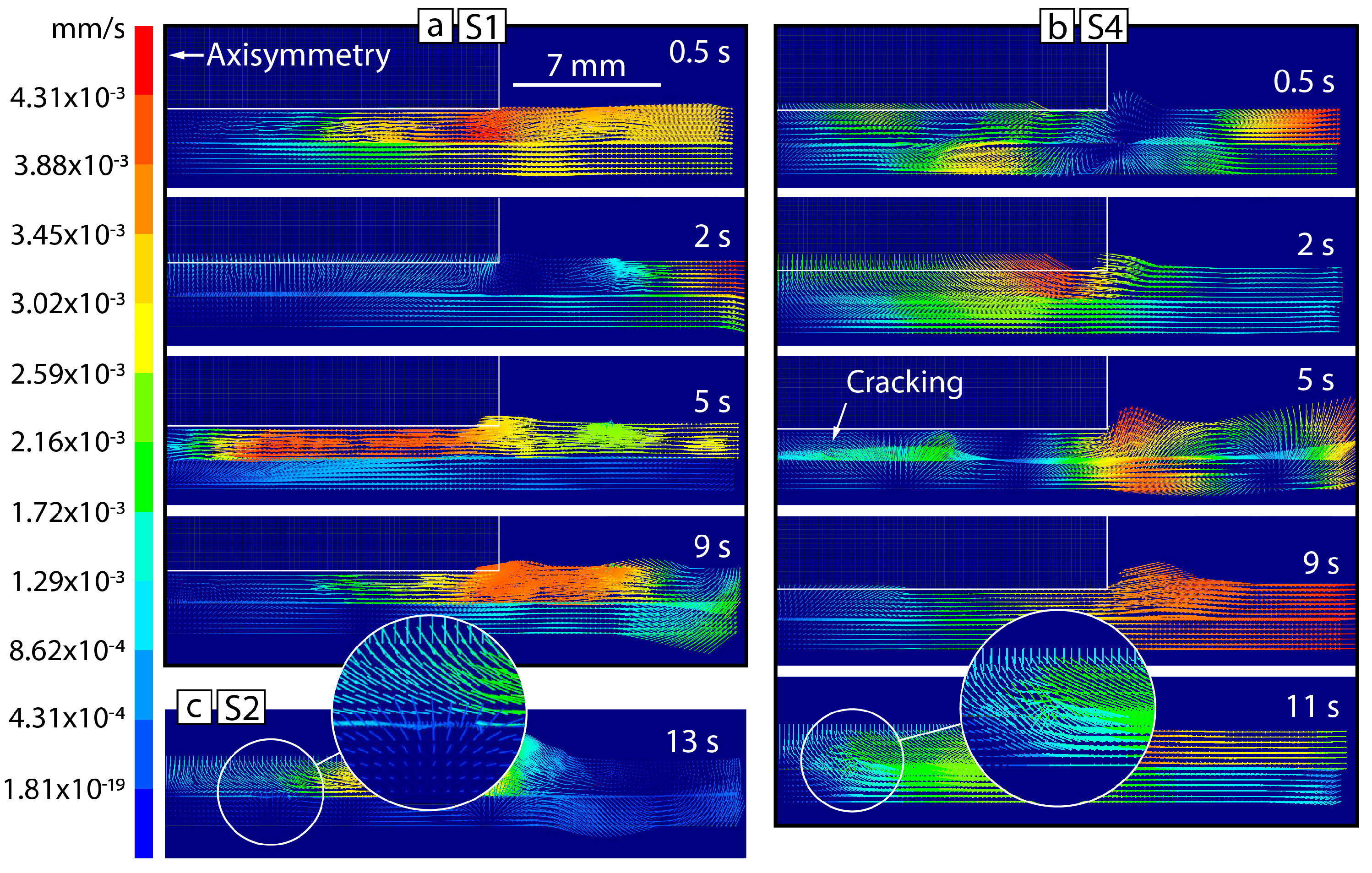
3.6. Temperature Field and Material Flow Simulation

Figure 11 shows the temperature distribution in samples S1 and S4, obtained under limited process parameters. In both cases, a rise in temperature occurred rapidly during the start of the plunge stage, with its location close to the outer edge of the shoulder (Figure 11a,b at 0.5 s). Sample S4 had a greater temperature due to the higher rotational speed. With the progression of the process, a decrease in temperature was expressed due to its transition from the periphery to the center of the spot weld. Sample S1, made under 1000 rpm, exhibited a gradual temperature transition to the center of the shoulder within 5 s (Figure 11a at 5 s). However, such a combination of process parameters did not reach a decrease in temperature during the whole process, while the temperature distribution in sample S2, made with a longer dwelling time, had a decrease in temperature after 12 s, with its slight partial concentration along the joining line (Figure 11c).
Sample S4, obtained at 1500 rpm, revealed a quick temperature transition to the center of the shoulder for 2 s without stabilization, as was presented in sample S1 under 1000 rpm (Figure 11b at 2 s). Together with this, the higher rotational speed allowed to achieve a decrease in temperature after 9 s of P-FSSW (Figure 11b at 9 s). The transition of the temperature to the center occurred with its partial concentration along the joining line (Figure 11b at 2 and 5 s). Going back to the results on the microstructure in samples S2 and S4 (see Figure 7b,d), this partial concentration of temperature (Figure 11b,c) may represent the formation of a mixed area between the aluminum plate and the Al-Si coating.
Such temperature behavior corresponded to a distinctive material flow. Namely, sample S1 exhibited a gradual and mostly uniform material flow in the outward direction of the shoulder for the whole processing time (Figure 12a), while the longer dwelling in sample S2 resulted in a slight increase of the material flow close to the center at 13 s (Figure 12c). The rotational speed of 1500 rpm resulted in a more intensive material flow for the first few seconds (Figure 12b). At 5 s, the material flow was slightly concentrated close to the center along the joining line between the aluminum plate and Al-Si coating (Figure 12b at 5 s), which correlates with fast shifting of the temperature to the center in the samples made at 1500 rpm (see Figure 11b). This behavior might result in cracking during the real experiment for sample S3 when the welding cycle is finished at 10 s (see Figure 6c). In contrast, increasing the dwell time in sample S4 caused an intensive material flow close to the center of the shoulder (Figure 12b at 11 s).

4. Conclusions

Dissimilar thin plates of AA6082-T6 and USIBOR®1500-AS coated with an Al-Si layer were lap-joined using Probeless Friction Stir Spot Welding (P-FSSW) under various process parameters. The microstructure and the joining interface were characterized. The experimental results indicated the following:
  • The adoption of an Al-Si coating on the UHSS steel promoted the interfacial bonding between the aluminum plate and the coated steel under a higher rotational speed of 1500 rpm, preventing oxidative coating wear. In the samples obtained at 1000 rpm, interfacial bonding was barely observed due to the presence of surface oxides.
  • Thermo-mechanical deformation occurred solely within the upper aluminum plate. The amount of heat input was mostly influenced by the rotational speed, resulting in a wider grain refinement area within the aluminum plate.
  • A dwell time of 15 s at rotational speeds of both 1000 rpm and 1500 rpm was responsible for a partial temperature concentration, which represents the formation of a mixed area between the aluminum plate and Al-Si coating.
  • Coupling the numerical results on the temperature and material flow, employing both dwell times of 10 s and 15 s and a rotational speed of 1000 rpm created cracks in the upper aluminum plate due to insufficient material plastitization. The formation of cracks also occurred at a rotational speed of 1500 rpm with a shorter dwell time of 10 s owing to less intensity of the material flow being concentrated at the center of the weld spot at 5 s of P-FSSW process. In contrast, an extended dwell time under 1500 rpm promoted a more vigorous material flow at 11 s through the process, effectively eliminating the incidence of cracking.

Author Contributions

Conceptualization, M.R., M.E.P. and N.C.; data curation, M.R., M.E.P. and N.C.; methodology, N.C. and G.C.; investigation, M.R. and M.E.P.; supervision, N.C.; validation, L.T. and G.C.; writing—original draft, M.R.; writing—review and editing, N.C., L.T., M.R., M.E.P. and G.C. All authors have read and agreed to the published version of the manuscript.

Funding

This work was partly supported by the “World-Class Science Center” program Advanced Digital Technologies (Grant Agreement No. 075-15-2022-312, dated 20 April 2022).

Data Availability Statement

Data will be made available at the reader’s request.

Conflicts of Interest

The authors declare no conflicts of interest.

References

  1. Czerwinski, F. Current trends in automotive lightweighting strategies and materials. Materials 2021, 14, 6631. [Google Scholar] [CrossRef]
  2. Yang, J.; Oliveira, J.P.; Li, Y.; Tan, C.; Gao, C.; Zhao, Y.; Yu, Z. Laser techniques for dissimilar joining of aluminum alloys to steels: A critical review. J. Mater. Process. Technol. 2022, 301, 117443. [Google Scholar] [CrossRef]
  3. Fan, D.W.; De Cooman, B.C. State-of-the-Knowledge on Coating Systems for Hot Stamped Parts. Steel Res. Int. 2012, 83, 412–433. [Google Scholar] [CrossRef]
  4. Kucera, V.; Cabibbo, M.; Prusa, F.; Fojt, J.; Petr-Soini, J.; Pilvousek, T.; Kolarikova, M.; Vojtech, D. Phase Composition of Al-Si Coating from the Initial State to the Hot-Stamped Condition. Materials 2021, 14, 1125. [Google Scholar] [CrossRef] [PubMed]
  5. Zheng, M.; Yang, J.; Xu, J.; Jiang, J.; Zhang, H.; Oliveira, J.P.; Lv, X.; Xue, J.; Li, Z. Interfacial microstructure and strengthening mechanism of dissimilar laser al/steel joint via a porous high entropy alloy coating. J. Mater. Res. Technol. 2023, 23, 3997–4011. [Google Scholar] [CrossRef]
  6. Fedorov, V.; Uhlig, T.; Wagner, G. Joining of aluminum and stainless steel using AlSi10 brazing filler: Microstructure and mechanical properties. AIP Conf. Proc. 2017, 1, 1858. [Google Scholar] [CrossRef]
  7. Zhang, W.; Sun, D.; Han, L.; Liu, D. Interfacial microstructure and mechanical property of resistance spot welded joint of high strength steel and aluminium alloy with 4047 AlSi12 interlayer. Mater. Des. 2014, 57, 186–194. [Google Scholar] [CrossRef]
  8. Zheng, M.; Zhang, H.; Gao, Y.; Zhao, Y.; Tan, C.; Song, X.; Yang, J. Influence of porous high entropy alloy coating on wetting behavior and interfacial microstructure of Al-Si alloy on steel substrate. J. Alloys Compd. 2022, 912, 165154. [Google Scholar] [CrossRef]
  9. Dheerendra, K.D. Dissimilar Metal Joining; Springer Nature Singapore Pte Ltd.: Singapore, 2023. [Google Scholar] [CrossRef]
  10. Tarasov, S.; Rubtsov, V.; Kolubaev, E. A proposed diffusion-controlled wear mechanism of alloy steel friction stir welding (FSW) tools used on an aluminum alloy. Wear 2014, 318, 130–134. [Google Scholar] [CrossRef]
  11. Sahlot, P.; Arora, A. Numerical model for prediction of tool wear and worn-out pin profile during friction stir welding. Wear 2018, 408, 96–107. [Google Scholar] [CrossRef]
  12. Li, S.; Chen, Y.; Kang, J.; Amirkhiz, B.S.; Nadeau, F. Friction stir lap welding of aluminum alloy to advanced high strength steel using a cold-spray deposition as an interlayer. Mater. Lett. 2019, 239, 212–215. [Google Scholar] [CrossRef]
  13. Schilling, C.; Dos Santos, J. Method and Device for Joining at Least Two Adjoining Work Pieces by Friction Welding. Google Patents US20020179682A1, 5 December 2002. [Google Scholar]
  14. Silva, B.H.; Zepon, G.; Bolfarini, C.; Dos Santos, J.F. Refill friction stir spot welding of AA6082-T6 alloy: Hook defect formation and its influence on the mechanical properties and fracture behavior. Mater. Sci. Eng. 2020, 773, 138724. [Google Scholar] [CrossRef]
  15. Tozaki, Y.; Uematsu, Y.; Tokaji, K. A newly developed tool without probe for friction stir spot welding and its performance. J. Mater. Process. Technol. 2010, 210, 844–851. [Google Scholar] [CrossRef]
  16. Li, W.; Li, J.; Zhang, Z.; Gao, D.; Wang, W.; Dong, C. Improving mechanical properties of pinless friction stir spot welded joints by eliminating hook defect. Mater. Des. 2014, 62, 247–254. [Google Scholar] [CrossRef]
  17. Lee, W.B.; Schmuecker, M.; Mercardo, U.A.; Biallas, G.; Jung, S.B. Interfacial reaction in steel–aluminum joints made by friction stir welding. Scr. Mater. 2006, 55, 355–358. [Google Scholar] [CrossRef]
  18. Da Silva, A.A.M.; Aldanondo, E.; Alvarez, P.; Arrurti, E.; Echeverría, A. Friction stir spot welding of AA 1050 Al alloy and hot stamped boron steel (22MnB5). Sci. Technol. Weld. Join. 2010, 15, 682–687. [Google Scholar] [CrossRef]
  19. Shen, Z.; Ding, Y.; Chen, J.; Shalch Amirkhiz, B.; Wen, J.Z.; Fu, L.; Gerlich, A.P. Interfacial bonding mechanism in Al/coated steel dissimilar refill friction stir spot welds. J. Mater. Sci. Technol. 2019, 35, 1027–1038. [Google Scholar] [CrossRef]
  20. Watanabe, M.; Feng, K.; Nakamura, Y.; Kumai, Y. Growth manner of intermetallic compound layer produced at welding interface of friction stir spot welded aluminum/steel lap joint. Mater. Trans. 2011, 52, 953–959. [Google Scholar] [CrossRef]
  21. Ishak, I.; Uematsu, Y.; Kakiuchi, T.; Tozaki, Y.; Mizutani, Y. Fatigue behaviour of dissimilar Al alloy/galvanised steel friction stir spot welds fabricated by scroll grooved tool without probe. Sci. Technol. Weld. Join. 2015, 20, 670–678. [Google Scholar] [CrossRef]
  22. Contuzzi, N.; Rashkovets, M.; Casalino, G. Numerical and experimental investigation of probeless friction stir spot welding of a multilayer aluminium alloy compound. Sci. Technol. Weld. Join. 2023, 1, 653–661. [Google Scholar] [CrossRef]
  23. Simufact Forming Manual Guide. 2021. Available online: https://nexus.hexagon.com/documentationcenter/bundle/Simufact_Forming_2021_Basics/resource/Simufact_Forming_2021_Basics.pdf (accessed on 30 December 2023).
  24. Chu, Q.; Yang, X.; Li, W. Microstructure and mechanical behaviour of pinless friction stir spot welded AA2198 joints. Sci. Technol. Weld. Join. 2016, 21, 164–170. [Google Scholar] [CrossRef]
  25. Oladimeji, O.O.; Taban, E.; Kaluc, E. Understanding the role of welding parameters and tool profile on the morphology and properties of expelled flash of spot welds. Mater. Des. 2016, 108, 518–528. [Google Scholar] [CrossRef]
  26. Rashkovets, M.; Contuzzi, N.; Casalino, G. Modeling of probeless friction stir spot welding of AA2024/AISI304 steel lap joint. Materials 2022, 15, 8205. [Google Scholar] [CrossRef]
  27. Reilly, A.; Shercliff, H.; Chen, Y.; Prangnel, P. Modelling and visualisation of material flow in friction stir spot welding. J. Mater. Process. Technol. 2015, 225, 473–484. [Google Scholar] [CrossRef]
  28. Sato, Y.S.; Kokawa, H.; Enomoto, M.; Jogan, S. Microstructural evolution of 6063 aluminum during friction-stir welding. Metall. Mater. Trans. A Phys. 1999, 30, 2429–2437. [Google Scholar] [CrossRef]
  29. Buckley, D.H. Surface films and metallurgy related to lubrication and wear. Prog. Surf. Sci. 1982, 12, 1–153. [Google Scholar] [CrossRef]
Figure 1. Initial microstructure of AA6082-T6 (a) and USIBOR®1500-AS steel (b).
Jmmp 08 00055 g001
Figure 2. Probeless tool (a) and scheme of P-FSSW process (b).
Jmmp 08 00055 g002
Figure 3. Spot-welded surface: sample S1 (a); sample S2 (b); sample S3 (c); sample S4 (d).
Jmmp 08 00055 g003
Figure 4. Cross-sections on the left (1), at the center (2), and on the right (3) side of sample S1 (a), sample S3 (b), sample S2 (c), and sample S4 (d).
Jmmp 08 00055 g004
Figure 5. Optical microstructure of AA6082 plate of samples S1 (a), S2 (b), S3 (c), and S4 (d). The dashed lines delineate the distinct microstructural zones.
Jmmp 08 00055 g005
Figure 6. BSE SEM of upper SZ in samples S1 (a), S2 (b), S3 (c), and S4 (d).
Jmmp 08 00055 g006
Figure 7. Joining interface on the left (1), at the center (2), and on the right (3) side of sample S1 (a), sample S2 (b), sample S3 (c), and sample S4 (d).
Jmmp 08 00055 g007
Figure 8. EDS elemental distribution map across layer of FexAlySiz IMC phase in sample S4.
Jmmp 08 00055 g008
Figure 9. EDS elemental distribution maps across the joining interface in samples S1 (a), S2 (c), S3 (b), and S4 (d). The dashed lines delineate Al-Si layer.
Jmmp 08 00055 g009
Figure 10. Microhardness distribution in samples S1 (a), S2 (c), S3 (b), and S4 (d).
Jmmp 08 00055 g010
Figure 11. Temperature distribution within 13 s of P-FSSW in samples S1 (a), S4 (b), and S2 (c).
Jmmp 08 00055 g011
Figure 12. Material flow within 13 s of P-FSSW in samples S1 (a), S4 (b), and S2 (c).
Jmmp 08 00055 g012
Table 1. Chemical composition of base materials, wt.%.
AlloyAlCuMgMnSiFeCrZnTiC
AA 6082–T6Bal.≤0.10.6–1.20.4–1.00.7–1.3≤0.5≤0.25≤0.2≤0.1-
USIBOR®1500-AS≤0.1≤0.2-≤1.4≤0.4Bal.≤0.35-≤0.05≤0.25
Al-Si coatingBal.---10-----
Table 2. Process parameters of P-FSSW.
SampleRotational Speed, rpmDown Force, NDwell Time, s
S11000735010
S2100015
S3150010
S4150015
Disclaimer/Publisher’s Note: The statements, opinions and data contained in all publications are solely those of the individual author(s) and contributor(s) and not of MDPI and/or the editor(s). MDPI and/or the editor(s) disclaim responsibility for any injury to people or property resulting from any ideas, methods, instructions or products referred to in the content.

