Article

Numerical Analysis of the Flow by Using a Free Runner Downstream the Francis Turbine †

by
Alin Ilie Bosioc
1,*,
Raul-Alexandru Szakal
2,
Adrian Stuparu
1,* and
Romeo Susan-Resiga
1
1
Department of Mechanical Machines, Equipment and Transportation, Politehnica University Timișoara, Bv. Mihai Viteazu, No.1, RO-300222 Timișoara, Romania
2
Romanian Academy–Timisoara Branch, Bv. Mihai Viteazu, No. 24, RO-300223 Timișoara, Romania
*
Authors to whom correspondence should be addressed.
This paper was published in the Proceedings of the 18th Conference on Modelling Fluid Flow (CMFF’22), Budapest, Hungary, 30 August–2 September 2022.
Int. J. Turbomach. Propuls. Power 2023, 8(2), 14; https://doi.org/10.3390/ijtpp8020014
Submission received: 2 February 2023 / Revised: 5 April 2023 / Accepted: 7 April 2023 / Published: 4 May 2023

Abstract

:
The current requirements of industrialized countries require the use of as much renewable energy as possible. One significant problem with renewable energy is that the produced power fluctuates. Currently, the only method available for energy compensation in the shortest time is given by hydroelectric power plants. Instead, hydroelectric power plants (especially the plants equipped with hydraulic turbines with fixed blades) are designed to operate in the vicinity of the optimal operating point with a maximum ±10% deviation. The energy market requires that hydraulic turbines operate in an increasingly wide area between −35% to 20% from the optimum operating point. Operation of hydraulic turbines far from the optimum operating point involves the appearance downstream of the turbine of a decelerated swirling flow with hydraulic instabilities (known in the literature as the vortex rope). The main purpose of this paper is to investigate numerically a new concept by using a free runner downstream on the main hydraulic runner turbine more precisely in the draft tube cone. The free runner concept requires rotations at the runaway speed with vanishing mechanical torque. The main purpose is to redistribute the total pressure and the moment between the shaft and the periphery. In addition, the free runner does not modify the operating point of the main hydraulic turbine runner.

1. Introduction

The actual energy crisis increases the development of clean renewable energy (wind and solar), which makes introducing the electrical network a large fluctuating component. Therefore, many hydroelectric power plants are operated to flatten the fluctuation of wind and solar power. Although operating in an off-design condition for grid services (part load and high load), hydraulic turbines experience an abrupt decrease in terms of efficiency. An excess of residual swirl is ingested by the draft tube, downstream of the turbine runner [1,2,3,4]. When the hydraulic turbines operate in off-design conditions, the residual swirl from the discharge cone is the consequence of the mismatch between the flow generated by the wicked gates and the angular momentum extracted by the turbine runner [5]. In general, for all hydraulic turbines, the worst operating conditions are when the machine is operated at partial discharge. For the partial discharge regime, the residual swirl ingested by the conical diffuser of the draft tube leads to the development of the so-called vortex rope [6,7,8,9,10]. Usually, the vortex rope develops in all lengths of the discharge cone and is characterized by a well-defined fundamental frequency and pressure amplitude. According to Ciocan et al. [11] the fundamental frequency has values between 0.2 and 0.4 from the rotational frequency of the runner. The fundamental frequency is accompanied by a pressure amplitude, and the fluctuating pressure is responsible for the high vibrations in the discharge cone and the closest components [12,13,14]. With the development of hydraulic turbines, different methods have been designed, tested, and implemented to mitigate the undesirable effect of the vortex rope. These methods can be divided into passive (not requiring auxiliary power) and active (requiring auxiliary power and control loop) [15]. One of the first passive techniques was proposed in the 1980s by Thicke [16]. Later, many other passive technologies such as J-grooves mounted on the cone wall [17], fins [18], runner cone extensions [19], diaphragm mounted downstream the conical diffuser [20], radial protrusion of solid bodies [21], the flow-feedback method [22] and stator mounted downstream the runner [23] were investigated. Active control techniques such as air or water injections through various zones of the hydraulic turbine [24,25,26,27,28] and the magneto-rheological control technique [29,30] were also investigated. All these techniques have incontestable advantages, especially in part-load or full-load operations, but in all operating regimes of a hydraulic machine, they have some drawbacks (Kougias et al. [1]). Together with these control technics, various measuring and observing systems were used to quantify the impact of control technics on hydrodynamic phenomena developed in the conical diffuser. The most common types of investigations on the hydrodynamic flow field generated at part-load conditions are the pressure measurements at the wall of the conical diffuser and the 2D Laser Doppler Velocimetry (LDV) measurements. In addition to these, high-speed camera observations and 2D or 3D particle image velocimetry (PIV) were used. The 2D LDV system is a non-invasive method that allows measuring the velocity profiles in the conical diffusers, offering a wider image of the entire flow fields. In contrast, the tools used to measure pressure are difficult to fit within the flow and, for this reason, are often used on the wall of the conical diffuser [22,31,32,33].
The experimental analysis combined with numerical simulation can provide a full image of the flow of the hydraulic machinery. Accordingly, this paper presents and analyzes the flow in the conical diffuser by combining experimental investigation and numerical simulation. The experimental investigations performed in this paper consist of measurements of velocity profiles with Laser Doppler Velocimetry (LDV) and pressure pulsations respectively. The numerical simulation performed in this paper is validated first from the numerical simulation and, second, the vortex rope is extracted for the investigated cases. From the experimental and numerical analysis, the new concept of the free runner mounted downstream of the main runner is analyzed. The concept was introduced by Susan Resiga et al. [5] and was further designed in the simplest way possible (three straight blades) and tested to prove the idea.

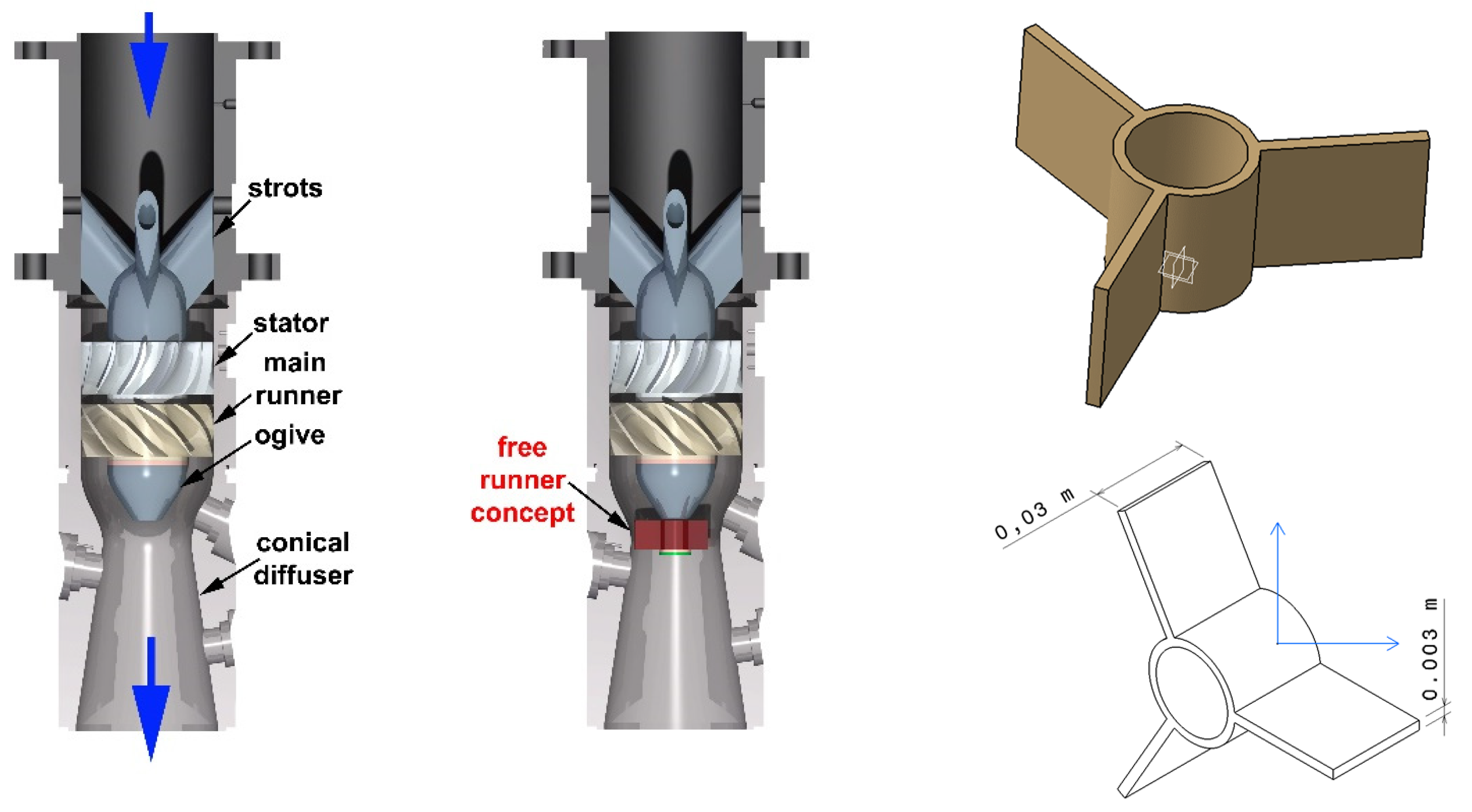
2. Experimental Setup

To analyze the decelerated swirling flow from the conical diffusers of the hydraulic turbines, model turbines or surrogate model turbines can be used. In our case, we have chosen a surrogate model, a swirl generator, capable of offering a decelerated swirling flow at the inlet in the conical diffuser similar to the flow outlet of a real hydraulic turbine [27,28].
The swirl apparatus is mounted on an experimental test rig developed in the laboratory, which serves by investigating different control methods by diminishing the flow instabilities associated with the vortex rope. Two main components are found in the swirl apparatus which is mounted on the main hydraulic circuit of the test rig: the swirl generator and the test section. The swirl generator has three components: the ogive, the stator and the main runner, which are mounted on a cylindrical Plexiglas section at an interior diameter of 0.150 m, as presented in Figure 1. The main runner and the stator generate at the inlet of the conical diffuser a rotating flow similar to the downstream flow of a Francis runner operated at a discharge of 70% from the nominal flow rate [11].
Downstream the main runner, on the experimental test rig the free runner concept was mounted, see Figure 1 (right). The free runner concept supposes that rotates at the runaway speed with vanishing mechanical torque. The main purpose is to redistribute the total pressure and the momentum between the shaft and the periphery so that the flux of the total pressure and the momentum are not altered. In addition, the free runner does not modify the operating point of the main hydraulic turbine runner. The benefits of the free runner approach downstream from the main-runner turbine are:
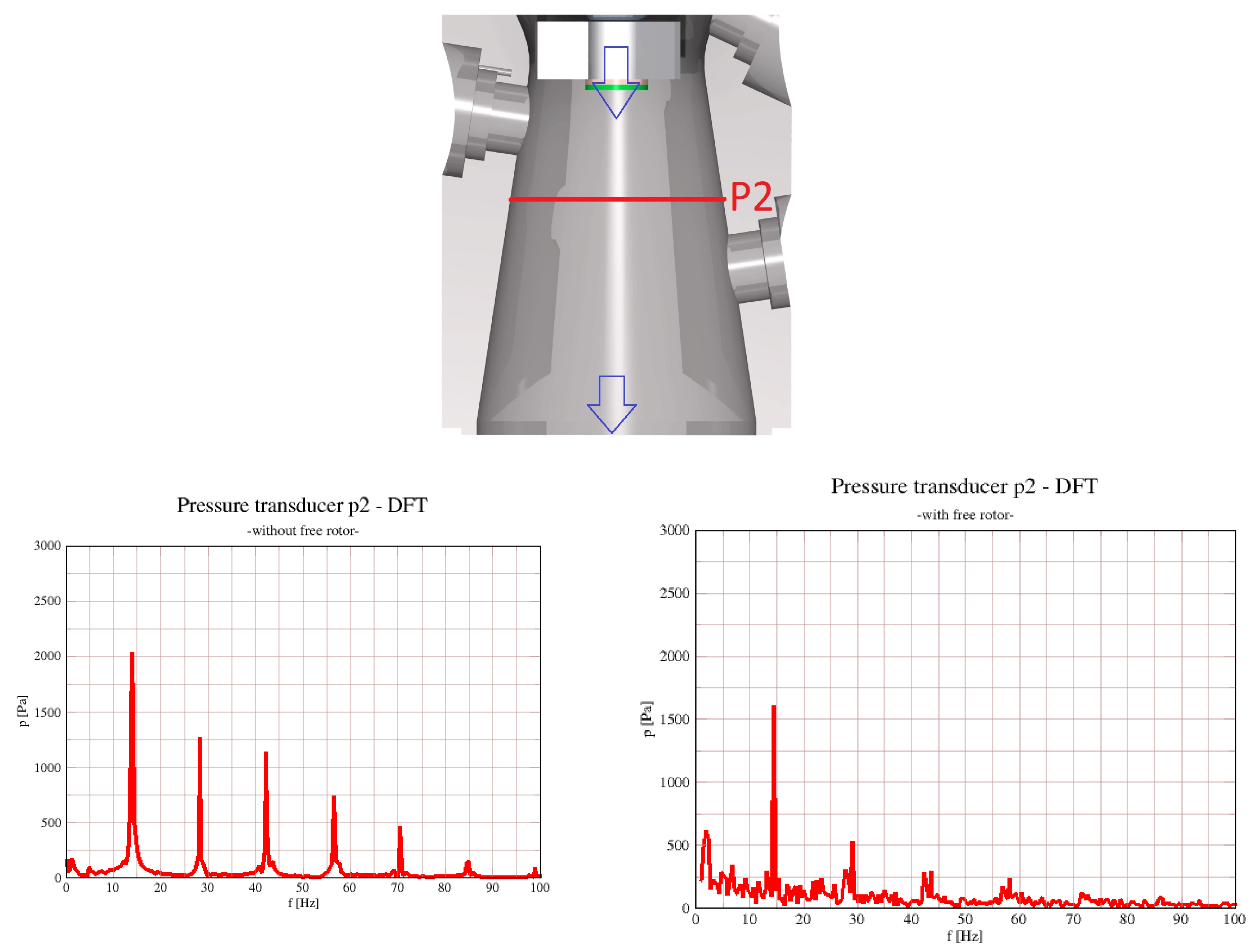
  • Diminish the pressure pulsations from the draft tube cone, by reducing the volume of the vortex rope.
  • Offer a better flow configuration at the inlet in the draft tube cone.
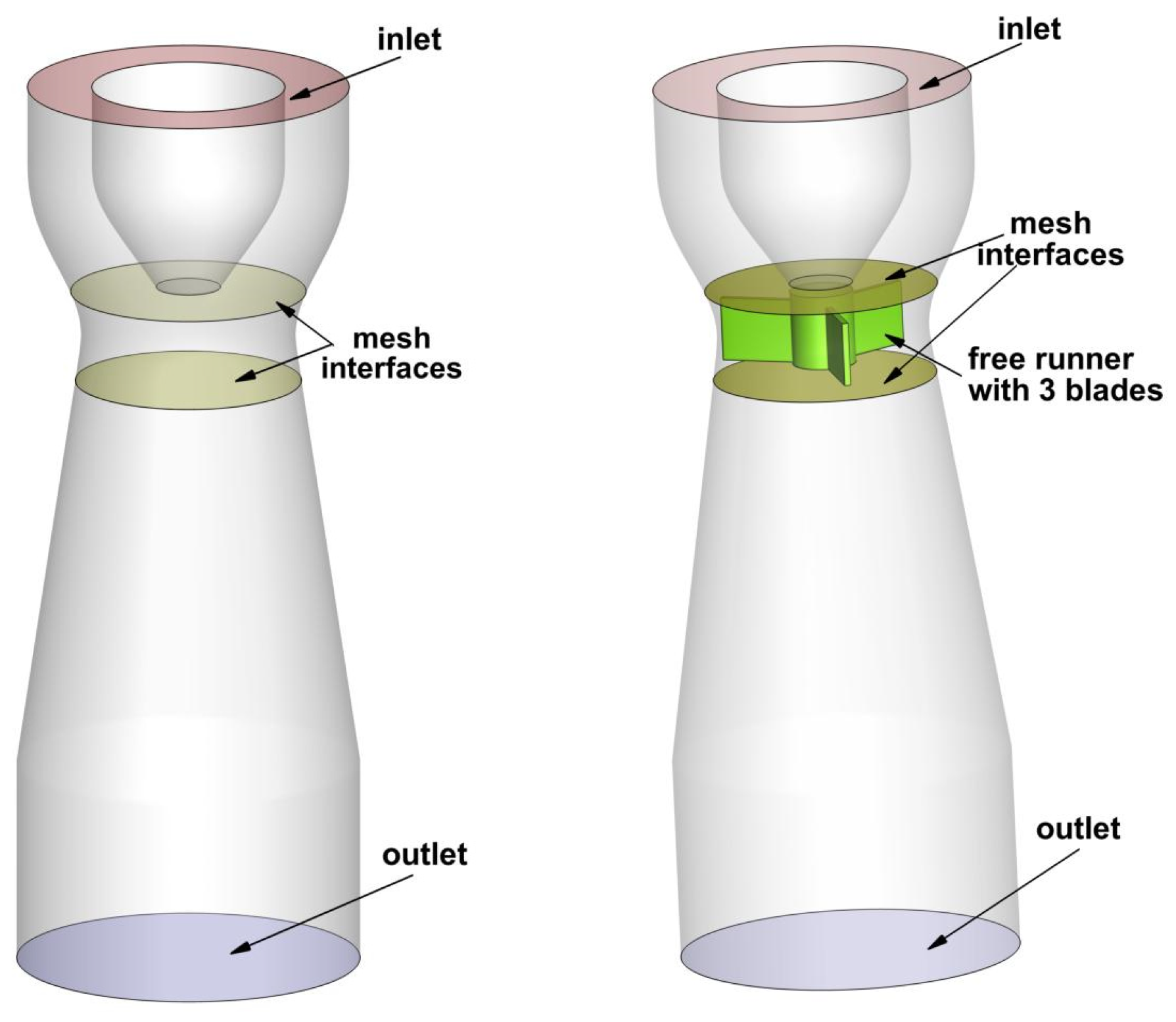
The free runner concept was introduced for the first time by Susan Resiga et al. [5], using the so-called Francis turbine with tandem runners. A similar approach can be found at Gokhman [22] using a stay apparatus downstream of the Francis runner. The free runner concept (see the sketch in Figure 1) downstream of the main turbine will add the required flexibility for the Francis turbine regulation and avoid deterioration of hydraulic turbine components.
The main dimensions of the components from the swirl apparatus, together with the dimensions of the free runner concept, are presented in the Table 1.
According with Table 1, the nominal discharge in the main hydraulic circuit was 0.03 m3/s for all measurements. The speed of the main runner was measured with the existing acquisition system in the laboratory, while the speed of the free runner was established with the help of the stroboscope.

3. Numerical Setup

The numerical domain was represented in full 3D and consists of 5.8 million mixed cells. First, the numerical results were obtained without considering the presence of the free runner, and, after developing the vortex rope, the free runner with three blades was activated, according with the Figure 2.
A numerical simulation was performed with the help of ANSYS Fluent 2021R1. The unsteady solver was employed, together with the Generalized k-ω (GEKO) model for modeling the turbulence parameters. The velocity components, together with the turbulence parameters, from the exit section of the swirl generator, obtained from experimental measurements, were imposed on the inlet boundary of the domain. On the outlet boundary, the outflow condition was imposed. For all wall boundary conditions, the Fluent default setup was retained, with no slip shear condition and standard roughness model [34,35].
To compute the interaction between the rotating domain, containing the free runner with three blades, and the static domain, the sliding mesh technique was employed, and two mesh interfaces were defined with the matching option activated, upstream and downstream of the free runner. The rotational speed imposed on the rotating domain was 850 rpm, corresponding to the free movement of the runner, and it was experimentally determined.
To generate the vortex rope, first, the presence of the free runner was “hidden” by defining the boundary condition on the blades as interior, and the volume was set as water. After the vortex rope was generated, the free runner was activated by imposing the wall boundary condition on the blades and the volume was set as solid.
As a solution method, the SIMPLEC scheme was used to calculate the pressure-velocity coupling. The spatial discretization was set to Second-Order Upwind for pressure, momentum, and turbulence parameters and to Least Squares Cell Based for the gradient. The transient formulation was set to Bounded Second-Order Implicit.
The time step was set at 0.001 s, which corresponds to a movement of the free runner of approximately 5°, and 15 iterations were considered for each time step. The numerical simulation was carried out for a flow time of 4.458 s for the case without the free runner and for a flow time of 2.505 s for the case with the free runner.

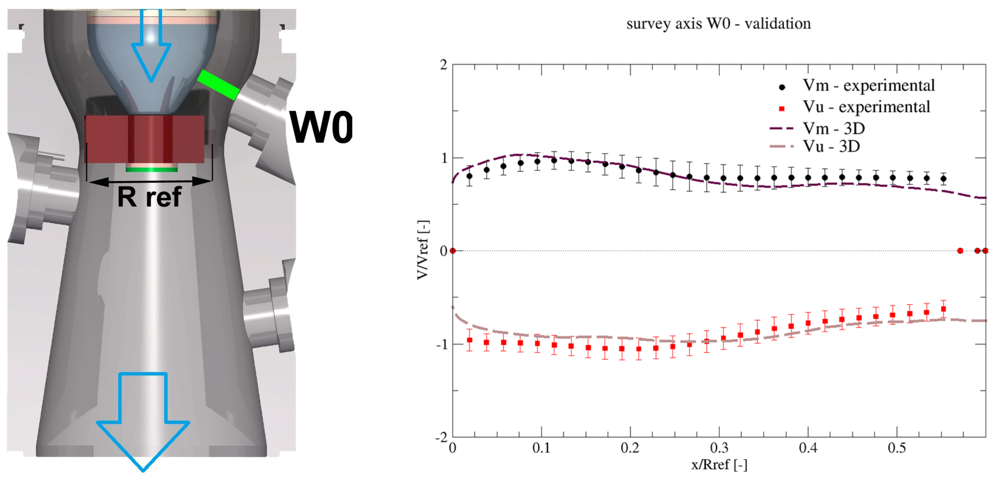
4. Validation of the Results

The first step in the analysis of the new concept is the validation of the velocity profiles obtained from the 3D numerical simulation against the experimental results. Measurements have been validated in the convergent part of the test section on the W0 survey axis. The comparison between the experimental analysis and the 3D numerical simulation shows that the numerical results agree very well with the experimental values. The comparison was centered on two velocity components: the meridional velocity and the circumferential velocity. Note that the experimental velocity components were used to validate the results of numerical simulations, not as boundary conditions. In Figure 3 (right), the length of the survey axis W0 (corresponding to the X axis in Figure 3) is presented in dimensionless form considering the reference radius Rref from the throat (the inlet in the conical diffuser). The velocity is presented in dimensionless form (corresponding to the Y axis), considering the throat velocity at a flow discharge of 0.03 m3/s.

5. Results and Analysis

Considering the good validation of the numerical investigation, the next step is the analysis of the flow and of the pressure from the numerical simulation for the investigated cases, without and with the free runner. Figure 4 presents the flow evaluation in the conical diffuser for both cases, analyzing the vortex rope formation. To visualize the vortex rope, a constant pressure iso-surface was plotted, with green color, and the vortex cores of the flow field were calculated and plotted, the red-colored spheres. The pictures show that the vortex rope is present in the conical diffuser in the case without a free runner (left part of the images). It is forming close to the ogive and continues 2/3 from the length of the conical diffuser. When the free runner is inserted into the extension of the ogive, the vortex rope starts to decrease in length and thickness. It forms at the end of the shaft of the free runner and continues approximately 1/3 from the length of the conical diffuser.
Another analysis consists of evaluating the unsteady pressure registered 100 mm downstream of the inlet in the conical diffuser, as shown in Figure 5. The unsteady pressure is registered from the numerical simulation and after the FFT was performed. The analysis of the FFT shows the main frequency of the vortex rope (14.5 Hz). In the case without the free runner, the maximum amplitude reaches a value of 2000 Pa. When the free runner is introduced, the maximum amplitude reaches a value of 1500 Pa, which means a reduction of 25%. Nevertheless, it is pointed out that this case is testing a simple free runner with only three straight blades.
Considering that the shape of the free runner blade is rectangular with a constant thickness of 3 mm, without a profiled leading edge and trailing edge, an evaluation of the total pressure was performed to determine the hydraulic losses. In the case without the free runner (with a developed vortex rope), the total pressure difference between the inlet and outlet in the numerical domain is 3695 Pa. When the free runner concept is implemented (with a diminished vortex rope), the total pressure difference is 4475 Pa. Therefore, in the case when the free runner is mounted at the inlet in the conical diffuser, the hydraulic losses increase by 21%. Further research with profiled blades on the free runner can better reduce hydraulic losses. Moreover, the minimum pressure moves from the ogive of the swirl generator (case without the free runner) to the shaft exit (case with the free runner), which means that neither the main runner nor the free runner works in cavitation.

6. Conclusions

In this paper, a new concept is proposed to diminish the hydrodynamic instabilities developed in the draft tube cone of hydraulic turbines. The concept is supposed to use a free runner (which rotates at the runaway speed) mounted downstream of the main hydraulic runner.
Considering that this is a new concept, the free runner was designed as simply as possible and was tested experimentally and numerically. The design of the free runner consists of using three rectangular sheets of metal with 3 mm thickness mounted on a shaft, between the main runner and the inlet in the conical diffuser. The ogive that closes the swirl generator was modified to sustain the free runner and allow it to rotate freely.
The experimental measurements and the numerical simulation have been performed without and with the free runner (at a speed of 850 rpm of the free runner). The vortex rope was evaluated from the 3D numerical simulation for both cases. It was clearly observed that when the free runner is installed, the vortex rope decreases in length and thickness. This conclusion can also be supported by the Fourier analysis of the unsteady pressure signals when the amplitude decreases by approximately 25% when the free runner is used. Nevertheless, the free runner concept investigated in this paper has used a simple runner with three straight blades only. Further investigations (a free runner with more blades and hydrodynamically designed) which are in progress, will confirm that the new concept could reduce the unsteadiness produced by the vortex rope.

Author Contributions

Conceptualization, A.I.B. and R.S.-R.; methodology, A.I.B. and R.S.-R.; software, A.S.; validation, A.I.B. and A.S.; investigation, A.I.B. and R.-A.S.; writing—original draft preparation A.I.B., R.-A.S. and A.S.; writing—review and editing, A.I.B., R.-A.S. and A.S. All authors have read and agreed to the published version of the manuscript.

Funding

This work was supported by a grant of the Romanian Ministry of Education and Research, CNCS-UEFISCDI, project number PN-III-P1-1.1-TE-2019-1594, within PNCDI III. The second author acknowledges the support of the Romanian Academy–Timișoara Branch thru the research programs of the Hydrodynamic, Cavitation, and Magnetic Liquid Division of the Center for Fundamental and Advanced Technical Research.

Institutional Review Board Statement

Not applicable.

Informed Consent Statement

Not applicable.

Data Availability Statement

Not applicable.

Conflicts of Interest

The authors declare no conflict of interest.

References

  1. Kougias, I.; Aggidis, G.; Avellan, F.; Deniz, S.; Lundin, U.; Moro, A.; Muntean, S.; Novara, D.; Pérez-Díaz, J.I.; Quaranta, E.; et al. Analysis of emerging technologies in the hydropower sector. Renew. Sustain. Energy Rev. 2019, 113, 109257. [Google Scholar] [CrossRef]
  2. Iliescu, M.S.; Ciocan, G.D.; Avellan, F. Analysis of the cavitating draft tube vortex in a Francis turbine using particle image velocimetry measurements in two-phase flow. J. Fluid Eng. 2008, 130, 146–157. [Google Scholar] [CrossRef]
  3. Neidhardt, T.; Magnoli, M.; Gummer, J. High part-load fluctuations in Francis turbines and the applicability of model test data. Hydro 2017, 2017, 1–10. [Google Scholar]
  4. Vu, T.C.; Retieb, S. Accuracy assessment of current CFD tools to predict hydraulic turbine efficiency hill chart. In Proceedings of the 21st IAHR Symposium on Hydraulic Machinery and Systems, Lausanne, Switzerland, 9–12 September 2002; pp. 93–198. [Google Scholar]
  5. Susan-Resiga, R.; Stuparu, A.; Muntean, S. Francis turbine with tandem runners: A proof of concept. IOP Conf. Ser. Earth Environ. Sci. 2019, 240, 1–8. [Google Scholar] [CrossRef]
  6. Kumar, S.; Cervantes, M.J.; Gandhi, B.K. Rotating vortex rope formation and mitigation in draft tube of hydro turbines—A review from experimental perspective. Renew. Sustain. Energy Rev. 2021, 136, 110354. [Google Scholar] [CrossRef]
  7. Mohammadi, M.; Hajidavalloo, E.; Behbahani-Nejad, M.J. Investigation on combined air and water injection in Francis turbine draft tube to reduce vortex rope. J. Fluid Eng. 2019, 141, 051301. [Google Scholar] [CrossRef]
  8. Pasche, S.; Avellan, F.; Gallaire, F. Part Load Vortex Rope as a Global Unstable Mode. J. Fluid Eng. 2017, 139, 1–12. [Google Scholar] [CrossRef]
  9. Nicolet, C.; Zobeiri, A.; Maruzewski, P.; Avellan, F. On the upper part load vortex rope in Francis turbine: Experimental investigation. IOP Conf. Ser. Earth Environ. Sci. 2010, 12, 012053. [Google Scholar] [CrossRef]
  10. Stuparu, A.; Resiga, R. The Complex Dynamics of the Precessing Vortex Rope in a Straight Diffuser. IOP Conf. Ser. Earth Environ. Sci. 2016, 49, 082013. [Google Scholar] [CrossRef]
  11. Ciocan, G.D.; Iliescu, M.S.; Vu, T.C.; Nennemann, B.; Avellan, F. Experimental study and numerical simulation of the FLINDT draft tube rotating vortex. J. Fluid Eng. 2007, 129, 146–158. [Google Scholar] [CrossRef]
  12. Cassidy, J.J.; Falvey, H.T. Observations of unsteady flow arising after vortex breakdown. J. Fluid Mech. 1970, 41, 727–736. [Google Scholar] [CrossRef]
  13. Falvey, H.T.; Cassidy, J.J. Frequency and amplitude of pressure surges generated by swirling flows. In Proceedings of the International Association of Hydraulic Research Symposium on Hydraulic Machinery and System, Stockholm, Sweden, 29 June–2 July 1970. [Google Scholar]
  14. Jacob, T.; Prenat, J.E. Francis turbine surge: Discussion and data base. In Proceedings of the Hydraulic Machinery and Cavitation: Proceedings of the XVIII IAHR Symposium on Hydraulic Machinery and Cavitation, Valencia, Spain, 16–19 September 1996; pp. 855–864. [Google Scholar]
  15. Grein, H. Vibration phenomena in Francis turbines: Their causes and prevention. Esccher Wyss News 1981, 54, 37–42. [Google Scholar]
  16. Thicke, R.H. Practical solutions for draft tube instability. Water Power Dam Constr. 1981, 33, 31–37. [Google Scholar]
  17. Kurokawa, J.; Imamura, H.; Choi, Y.-D. Effect of J-groove on the suppression of swirl flow in a conical diffuser. J. Fluid Eng. 2010, 132, 071101. [Google Scholar] [CrossRef]
  18. Nishi, M.; Wang, X.; Yoshida, K.; Takahashi, T.; Tsukamoto, T. An experimental study on fins, their role in control of the draft tube surging. In Proceedings of the Hydraulic Machinery and Cavitation: Proceedings of the XVIII IAHR Symposium on Hydraulic Machinery and Cavitation, Valencia, Spain, 16–19 September 1996; pp. 905–914. [Google Scholar]
  19. Qian, Z.; Li, W.; Huai, W.-X.; Wu, Y. The effect of runner cone design on pressure oscillation characteristics in a Francis hydraulic turbine. Proc. Inst. Mech. Eng. Part A J. Power Energy 2012, 226, 137–150. [Google Scholar] [CrossRef]
  20. Tănasă, C.; Bosioc, A.; Muntean, S.; Susan-Resiga, R. A Novel Passive Method to Control the Swirling Flow with Vortex Rope from the Conical Diffuser of Hydraulic Turbines with Fixed Blades. Appl. Sci. 2019, 9, 4910. [Google Scholar] [CrossRef]
  21. Shiraghaee, S.; Sundström, J.; Raisee, M.; Cervantes, M.J. Mitigation of Draft Tube Pressure Pulsations by Radial Protrusion of Solid Bodies into the Flow Field: An Experimental Investigation. IOP Conf. Ser. Earth Environ. Sci. 2021, 774, 012004. [Google Scholar] [CrossRef]
  22. Tanasa, C.; Susan-Resiga, R.; Muntea, S.; Bosioc, A.I. Flow-Feedback Method for Mitigating the Vortex Rope in Decelerated Swirling Flows. J. Fluid Eng. 2013, 135, 061304. [Google Scholar] [CrossRef]
  23. Gokhman, A. Hydraulic Turbine and Exit Stay Apparatus Therefor. US Patent 6 918 744 B2, 19 July 2005. [Google Scholar]
  24. Kjeldsen, M.; Olsen, K.; Nielsen, T.; Dahlhaug, O. Water injection for the mitigation of draft tube pressure pulsations. In Proceedings of the IAHR International Meeting of WG on Cavitation and Dynamic Problems in Hydraulic Machinery and Systems, Stuttgart, Germany, 9–11 October 2006. [Google Scholar]
  25. Adolfsson, S. Expanding Operation Ranges Using Active Flow Control in Francis Turbines. Bachelor’s Thesis, Umea University, Umea, Sweden, 2014. [Google Scholar]
  26. Blommaert, G.; Prenat, J.; Avellan, F.; Boyer, A. Active control of Francis turbine operation stability. In Proceedings of the 3rd ASME/JSME Joint Fluids Engineering Conference, San Francisco, CA, USA, 18–23 July 1999; pp. 1–8. [Google Scholar]
  27. Susan-Resiga, R.; Vu, T.C.; Muntean, S.; Ciocan, G.D.; Nennemann, B. Jet control of the draft tube vortex rope in Francis turbines at partial discharge. In Proceedings of the 23rd IAHR Symposium Conference, Yokohama, Japan, 17–21 October 2006; pp. 67–80. [Google Scholar]
  28. Bosioc, A.I.; Susan-Resiga, R.; Muntean, S.; Tanasa, C. Unsteady Pressure Analysis of a Swirling Flow with Vortex Rope and Axial Water Injection in a Discharge Cone. J. Fluid Eng. 2012, 134, 081104. [Google Scholar] [CrossRef]
  29. Bosioc, A.I.; Muntean, S.; Tanasa, C.; Susan-Resiga, R.; Vékás, L. Unsteady pressure measurements of decelerated swirling flow in a discharge cone at lower runner speeds. In Proceedings of the IOP Conference Series: Earth and Environmental Science, Montreal, QC, Canada, 22–26 September 2014; p. 22. [Google Scholar]
  30. Szakal, R.A.; Doman, A.; Muntean, S. Influence of the reshaped elbow on the unsteady pressure field in a simplified geometry of the draft tube. Energies 2021, 14, 1393. [Google Scholar] [CrossRef]
  31. Kirschner, O.; Ruprecht, A.; Göde, E.; Riedelbauch, S. Experimental investigation of pressure fluctuations caused by a vortex rope in a draft tube. In IOP Conference Series: Earth and Environmental Science; IOP Publishing: Bristol, UK, 2012; p. 15. [Google Scholar]
  32. Bosioc, A.I.; Tanasa, C.; Muntean, S.; Susan-Resiga, R.F. Pressure Recovery Improvement in a Conical Diffuser with Swirling Flow Using Water Jet Injection. Proc. Rom. Acad. Ser. A Math. Phys. Tech. Sci. Inf. Sci. 2010, 11, 245–252. [Google Scholar]
  33. Kirschner, O.; Ruprecht, A.; Göde, E. Experimental investigation of pressure pulsation in a simplified draft tube. In Proceedings of the 3rd IAHR International Meeting of the Workgroup on Cavitation and Dynamic Problems in Hydraulic Machinery and Systems, Brno, Czech Republic, 14–16 October 2009. [Google Scholar]
  34. Anton, A.A. Reconstruction of a space-time window in a transient simulation of the breaking of a dam. In Proceedings of the 6th IEEE International Symposium on Applied Computational Intelligence and Informatics (SACI), Timisoara, Romania, 19–21 May 2011; pp. 335–340. [Google Scholar]
  35. Anton, A.A. Numerical Investigation of Unsteady Flows using OpenFOAM. Hidraulica 2016, 1, 7–12. [Google Scholar]
Figure 1. Swirl apparatus and test section from the experimental test rig. The original configuration (left), the configuration with the free runner concept implemented on the test rig (middle), and the shape of the free runner concept with three blades with main dimensions (right).
Ijtpp 08 00014 g001
Figure 2. Full 3D domain: without free runner (left) and with free runner (right).
Ijtpp 08 00014 g002
Figure 3. Validation of the velocities measured experimentally with the LDV on the survey axis W0 with the velocity profiles obtained from the 3D numerical simulation).
Ijtpp 08 00014 g003
Figure 4. Visualization of the vortex rope for the case: without and with free runner.
Ijtpp 08 00014 g004
Figure 5. Evaluation of the Fourier transform on the point P2, 100 mm downstream of the inlet in the conical diffuser, for the cases without and with free runner from the numerical simulation.
Ijtpp 08 00014 g005
Table 1. Hydraulic parameters for the test rig and the main components.
ParameterValueUnit
Nominal discharge Qn0.03[m3/s]
Nominal pressure on the main reservoir30,000[Pa]
Main runner-rotational speed n940[rpm]
Main runner-tip diameter Dt0.150[m]
Main runner-hub diameter Dh0.06[m]
Main runner-blade number z10[-]
Free runner-rotational speed nfr850[rpm]
Free runner-tip diameter Dt-fr0.100[m]
Free runner-hub diameter Dh-fr0.03[m]
Free runner-blade number zfr3[-]
Disclaimer/Publisher’s Note: The statements, opinions and data contained in all publications are solely those of the individual author(s) and contributor(s) and not of MDPI and/or the editor(s). MDPI and/or the editor(s) disclaim responsibility for any injury to people or property resulting from any ideas, methods, instructions or products referred to in the content.

