Review

State of the Art on Two-Phase Non-Miscible Liquid/Gas Flow Transport Analysis in Radial Centrifugal Pumps Part C: CFD Approaches with Emphasis on Improved Models

Chair of Hydraulic Fluid Machinery, Ruhr University Bochum, Universitätsstr. 150, 44801 Bochum, Germany
*
Author to whom correspondence should be addressed.
Int. J. Turbomach. Propuls. Power 2023, 8(2), 15; https://doi.org/10.3390/ijtpp8020015
Submission received: 15 December 2022 / Revised: 11 April 2023 / Accepted: 18 April 2023 / Published: 4 May 2023
(This article belongs to the Special Issue Advances in Critical Aspects of Turbomachinery Components and Systems)

Abstract

:
Predicting pump performance and ensuring operational reliability under two-phase conditions is a major goal of three-dimensional (3D) computational fluid dynamics (CFD) analysis of liquid/gas radial centrifugal pump flows. Hence, 3D CFD methods are increasingly applied to such flows in academia and industry. The CFD analysis of liquid/gas pump flows demands careful selection of sub-models from several fields in CFD, such as two-phase and turbulence modeling, as well as high-quality meshing of complex geometries. This paper presents an overview of current CFD simulation strategies, and recent progress in two-phase modeling is outlined. Particular focus is given to different approaches for dispersed bubbly flow and coherent gas accumulations. For dispersed bubbly flow regions, Euler–Euler Two-Fluid models are discussed, including population balance and bubble interaction models. For coherent gas pocket flow, essentially interface-capturing Volume-of-Fluid methods are applied. A hybrid model is suggested, i.e., a combination of an Euler–Euler Two-Fluid model with interface-capturing properties, predicting bubbly flow regimes as well as regimes with coherent gas pockets. The importance of considering scale-resolving turbulence models for highly-unsteady two-phase flow regions is emphasized.

1. Introduction

In various industrial and engineering applications, a mixture of liquid and noncondensable gas, such as air, is encountered. Centrifugal pumps, which have been designed for single-phase liquid transport, are frequently required to convey two-phase mixtures. Two-phase pump applications can be found in nuclear [1] and geothermal [2] power stations, in the pulp and paper industry [3] or in the petroleum industry for artificial lifting [4]. Even a small load of gas may considerably disturb conveyance, and may even cause a break-down of the pump head [5]. As discussed in detail in Part A of this review paper series, a drop in the pump head is associated with a separation of air and water in the blade channels [3,6,7,8]. In pumps with high specific speeds, in terms of axial and mixed flow pumps, the action of the Coriolis force is directed from the shroud to the hub [9]. Thereby, secondary flow is promoted in the blade channels and this, to some extent, counteracts phase separation. In circumferential pumps, the Coriolis force acts in the direction of the blade pressure side. As a consequence, pressure gradients in the cross-flow direction develop. Since the densities of liquid and gas considerably deviate, pressure gradients lead to a slip between phases, and the gas tends to accumulate on the blade suction side, especially in part-load conditions, where the flow incidence at the blade trailing edge is high [10].
Although there is no difference in principle in the interaction of body forces in the liquid and the pressure gradients, which finally leads to phase segregation, the effect on segregation is considerably more pronounced for circumferential pumps, due to the direction of the Coriolis forces. Thus, this review of CFD methods is essentially confined to this pump type, with a few exceptions. In Section 2, a review of CFD methods is provided. Unlike the review of, for example, Zhu and Zhang [11], who provided a rather broad overview of 3D simulation techniques of submersible pumps, we substantially focus on aspects of multiphase modeling. Section 2 starts with the physical reasoning of the model assumptions obtained from high-fidelity experiments. Based on experimental observations, two main branches of multiphase models can be identified in terms of the Euler–Euler Two-Fluid (EE2F) method, on the one hand, and the Volume-of-Fluid (VoF) method, on the other hand. State of the art and limitations of both approaches are presented in Section 2.2 and Section 2.3, together with example results from the literature. It is important to note that cavitation, in terms of rapid phase change, is omitted here. Although cavitation and the mere transport of a gaseous phase in a liquid are closely related from a physical point of view [12,13,14,15], modeling approaches are still separated, so we confine our review to the latter. A discussion of cavitation in circumferential pumps is provided elsewhere, e.g., in Refs. [16,17,18,19,20,21,22,23].

2. Review of CFD Methods for Multiphase Flow in Pumps

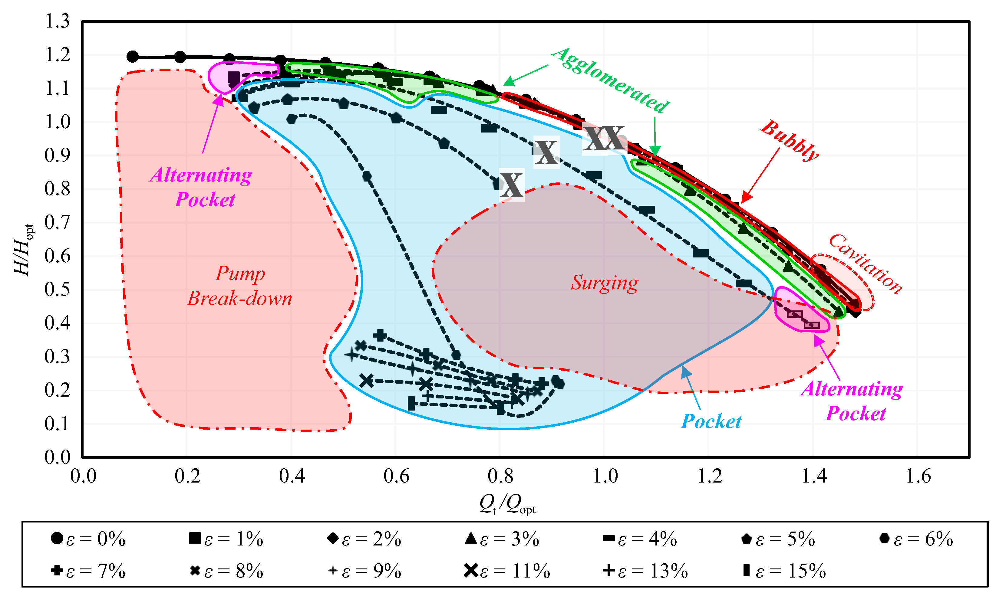
2.1. Physical Reasoning

We start our review with important observations from experiments. Recent optical [24,25,26,27], Gamma [28,29,30,31] and X-Ray [32] experimental techniques provide detailed views of the multiphase flow fields in rotating systems. Based on the multiphase flow field, together with head drop characteristics, several authors [4,24,25,26,27,33,34,35,36,37,38] provide performance maps of the mixture conveying. Subject to the operation point and the air loading, Mansour et al. [24,25,26,27] observed a transition from bubbly flow to steady air accumulations in the blade channel, and introduced a categorization in terms of flow regime maps. Four different flow regimes are illustrated in the pump head performance map shown in Figure 1 for a semi-open impeller. It is noteworthy that, for a closed impeller, as investigated by Mansour et al. [24,25], a fifth regime, in terms of segregated flow regimes, was observed, where an air pocket is attached over the entire extent of the blade. This segregated flow regime is not present in a semi-open impeller due to the strong mixing effect, which flushes away parts of the attached air pockets. The flow regimes in semi-open impellers can be summarized as follows:
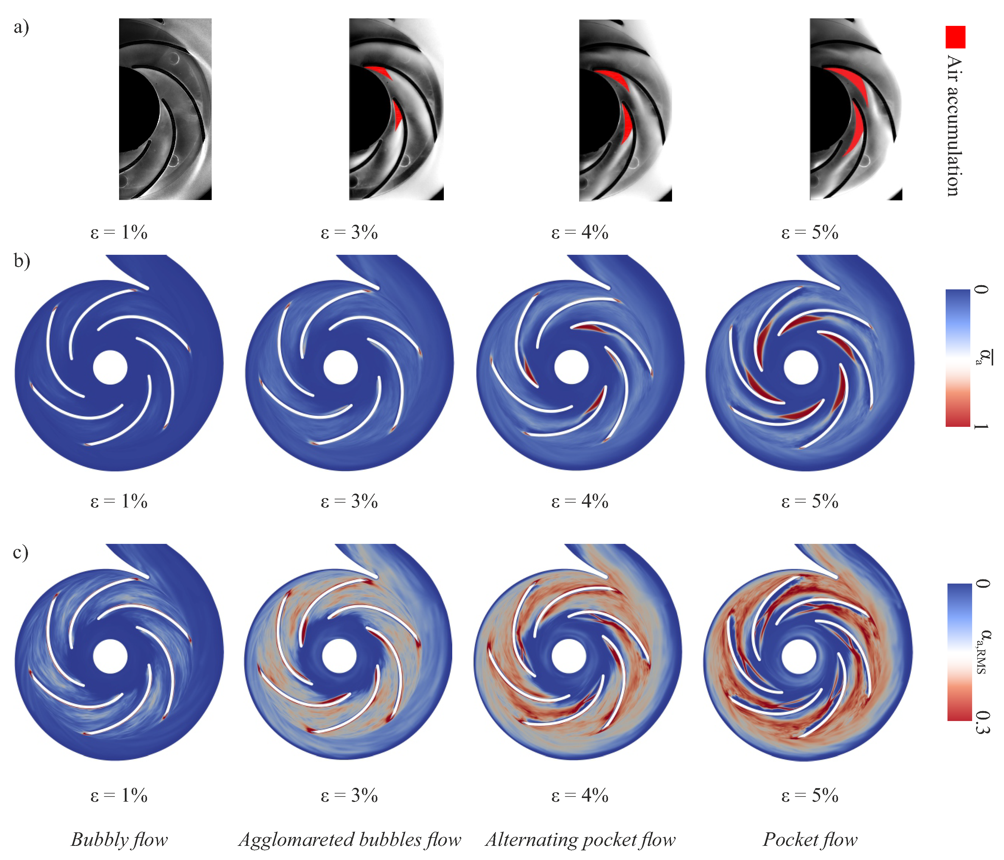
  • Bubbly flow: the air bubbles are dispersed everywhere in the impeller.
  • Agglomerated bubbles flow: air bubbles start to accumulate in small bubble clusters.
  • Alternating pocket flow: highly unsteady air pockets, with strongly variable sizes and locations, appear at the impeller blades but are not located at each blade.
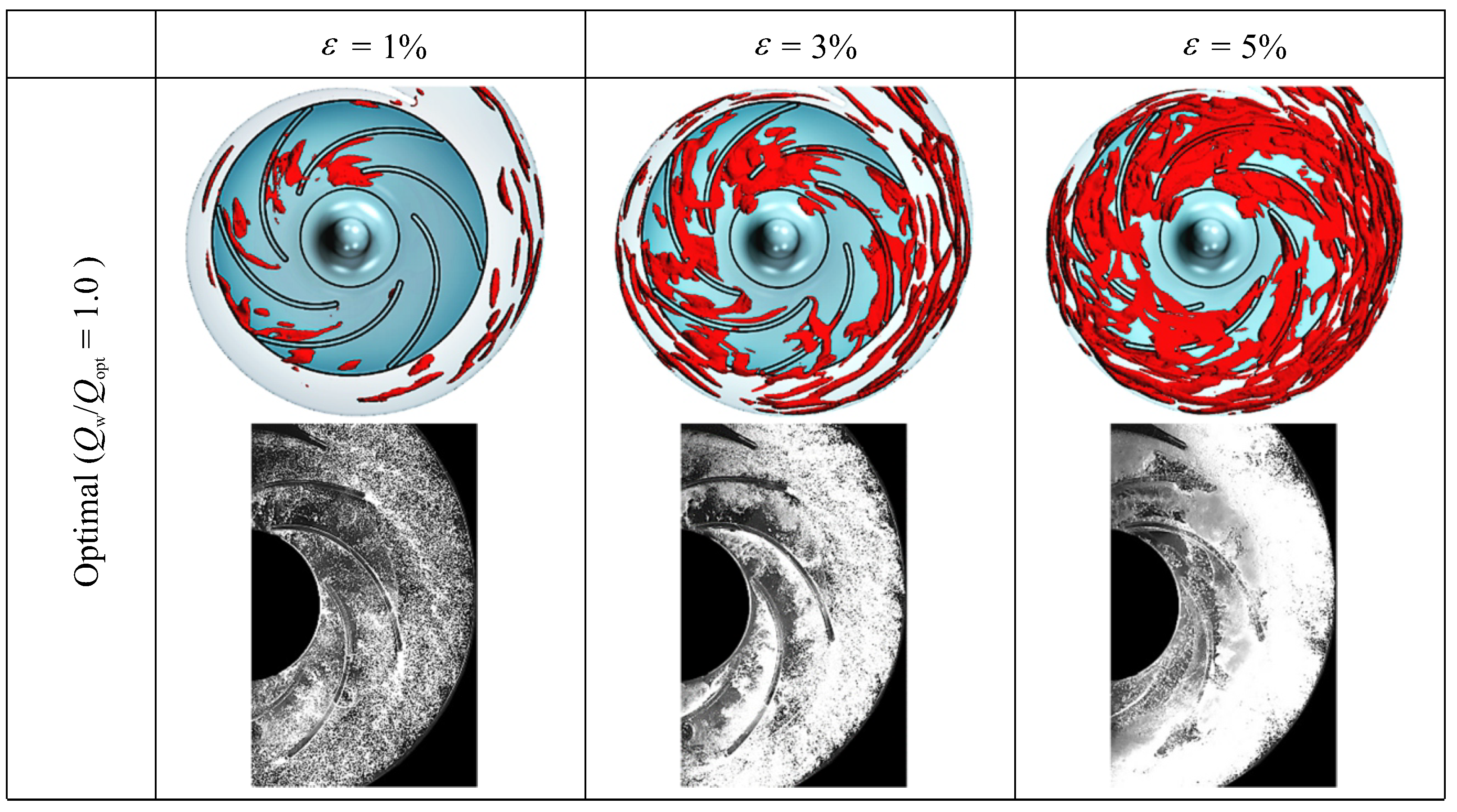
  • Pocket flow: stable and steady air pockets are located at the suction side of each blade.
The different flow regimes make various demands on the simulation method. For example, the direct resolution of all phase interfaces in the bubbly flow regime (1), where a multitude of separated bubbles is dispersed in the liquid, is associated with tremendous computational effort. Therefore, a homogeneous mixture approach, with treatment of separate bubbles on the subgrid scale, is more efficient when small interfacial scales, in terms of bubbles, are present, and corresponding studies are summarized in Section 2.2. On the other hand, a large coherent air regime is present in the pocket flow regime (4), and the assumptions of a homogeneous mixture approach are violated. Instead, a sharp resolution of the phase interface by means of, for example, a VoF scheme, might be more appropriate. Corresponding studies are reviewed in Section 2.3. In between, in regimes (2) and (3), a transition of phase morphology within the impeller is present. What is more, even when a pocket flow regime (4) has developed in the blade passage, a bubbly flow may be present at the same time, for example, in the suction pipe. Due to these different flow regimes present in the pump, it can be concluded that the transition of phase morphology from bubbly flow to coherent air accumulations should be captured by the CFD method. This demands a hybrid approach, which is summarized in Section 2.4.
A further experimental observation corresponds to highly unsteady void regions, described, for example, in Refs. [24,25,26,27,39,40,41,42,43,44]. As discussed above, alternating unsteady pockets are present in the transition zone between bubbly and pocket flow regimes. Even inherently steady adherent void regions in the pocket flow regime show unsteady wakes, which will be discussed in Section 4. This observation should be taken into account by reasonable turbulence models. For highly unsteady flow, the validity of Reynolds-averaging might be challenged, and turbulence-scale resolving models might be more accurate. Therefore, a brief review of turbulence-scale resolving simulations of pump flow is provided in Section 2.5.
Figure 1. Performance map to characterize flow regimes observed in the experiments of Mansour et al. [27,39]. Some operational points are marked with an “X”, and are slightly pulled apart for clarity due to their proximity. They are picked up in the flow simulations further below.
Ijtpp 08 00015 g001

2.2. Euler–Euler Two-Fluid (EE2F) Approach

Most available studies on radial centrifugal pump flow have been performed using the EE2F model family. An Eulerian approach for the dispersed phase is preferred to the Lagrangian approach, since more moderate grid dependence and better statistical convergence of the Eulerian approach may be assumed [45]. Early simulations of two-phase flow in centrifugal pumps by Pak and Lee [46] and Minemura and Uchiyama [47] pointed out that bubbles move to the blade tip and accumulate on the blade’s suction side and that the head drop is associated with phase separation and large air accumulation zones. Even with a simplified monodisperse approach and single-channel simulations, Müller et al. [48] obtained good agreement with the measured head drop at low air loading, while, with a rise in the inlet gas volume fraction, even a qualitative prediction could not be obtained, confirming the conclusion of several previous studies, e.g., [49,50,51]. A significant influence of the computational grid quality on the location and size of bubble accumulation was found by Müller et al. [52]. Si et al. [40,41,42] and Wang et al. [53] presented validated numerical results of a 3D-bladed centrifugal pump in two-phase air–water flow and compared different impeller designs. Zhou et al. [54] investigated transient, i.e., time-resolved, characteristics of the radial pump force, and Zhong et al. [55] analyzed the transient pump characteristics that start when air is injected in the suction pipe. The EE2F model was also adopted in our previous studies, comparing a closed and a semi-open impeller [56,57,58]. Several authors have utilized polydisperse bubble size distribution, together with population balance modeling (PBM) within the EE2F framework, enabling temporal and spatial variation of the bubble size. He et al. [59] highlighted the importance of considering the change of bubble diameter for volute-type centrifugal pumps and compared these results to the results of a monodisperse EE2F simulation. An example result obtained by He et al. [59], in terms of the distribution of the air volume fraction α a , is given in Figure 2. Stronger air aggregation was observed with the EE2F–PBM model than with the monodisperse approach, supposedly because the chosen monodisperse bubble diameter was too small. The benefit of using a PBM in combination with the EE2F approach is emphasized by having a better match to experimental data.
Yan et al. [60] confirmed this conclusion. In Figure 3, the pump’s pressure coefficient versus inlet gas volume fraction is given for the simulation results obtained by a coupled EE2F–PBM and by a monodosperse EE2F. For the latter, the bubble diameter d was varied. By an adjustment of d, the experimental data could be approached. Thus, d can be considered a kind of calibration parameter in the monodisperse EE2F variant, which is dispensable for the polydisperse EE2F–PBM. With this coupled EE2F–PBM model, Yan et al. [60] analyzed the bubble size distribution in a multistage centrifugal pump.
It is important to note that the term homogeneous (abbreviated “Hom.” in Figure 3) used by the authors means that a common velocity field for water and air is assumed. This should not be confused with the homogeneous mixture approach, which means a treatment of bubbles on the subgrid scale and is inherent to any EE2F variant. The mismatch to data by using a common velocity field (result termed “Hom.” in Figure 3) underlines the necessity of distinct velocity fields for water and air, to enable phase segregation.
In the simulations by Stel et al. [61,62], air accumulation zones within the impeller observed in the experiments of the same research group from Ref. [37] could be reproduced. Zhang et al. [63] observed large bubble sizes in regions of high air loading within the pump impeller. Chen et al. [64] analyzed the head drop of the first stage of an electrical submersible pump (ESP). Recently, Si et al. [65] reproduced the head drop observed in measurements of a five-stage ESP. They showed that the most significant portion of the head drop occurs in the first and the second stages under two-phase flow conditions, which is underlined by Figure 4, in terms of the stage head coefficient Ψ . For single-phase, i.e., pure water flow, the first stage does most of the work, according to Figure 4a. For two-phase conditions and ε > 2 % , Ψ drops significantly for stages one and two, according to Figure 4b.
The EE2F model inherently presumes a dispersed bubbly flow [58], i.e., a homogeneous mixture of water and air within each computational cell. Thus, it can be assumed that in the EE2F approach, air accumulations are represented by clustering of densely dispersed bubbles. However, in the experimental investigations on a planar diffuser flow [66], a sharp interface between the water and the air accumulations was observed, which points out a coherent attached air structure, rather than a clustering of separated bubbles. It may be concluded that such large interface structures should be resolved by a VoF rather than an EE2F approach [67], which is outlined next.

2.3. Volume-of-Fluid (VoF) Approach

By utilizing a VoF approach, Parikh et al. [68] optimized an inducer design by employing a multi-objective optimization and assessed the influence of the inducer design on the pump flow. The same authors investigated the air distribution for different semi-open impellers [69], and compared these simulation results with the experimental results from the same research group [24,25,39]. For example, the air distribution is shown in Figure 5 for a variation of the inlet gas volume fraction. Parikh et al. [69] concluded that the instantaneous distribution of void regions observed in the experiments by a scattered-light technique could be reproduced well by the void fraction distribution in the simulation. However, steady air accumulations formed in the impeller channels for ε 3 % , according to the experiments, which were not observed in the VoF simulation results.
Pineda et al. [70] utilized the VoF method for flow simulations in ESPs and experienced up to 25% deviation from the results of the experimentally measured pump head. Zhu et al. [71] concluded that the VoF model is inferior to the EE2F model for the simulation of ESP flows. Mansour et al. [72] figured out the important physical mechanisms of attenuating pump performance and the beneficial effect of an inducer. However, it remains unclear if the spatial resolution limit allows an adequate resolution of void structures within the VoF simulations. According to De Santis et al. [73], VoF methods are only appropriate for capturing large interfacial structures, provided that a high spatial resolution is applied. Hundshagen et al. [74] showed that the grid resolution, which is feasible in centrifugal pumps, is by far too coarse to resolve all small scales encountered in bubbly, dispersed flow regimes. It is worth noting that, of course, like VoF methods, level set methods also provide an interface resolution. However, to the best knowledge of the authors, there are no centrifugal pump flow studies employing level set methods.

2.4. Hybrid Two-Phase (H2P) Approach

When using the EE2F and VOF approaches, two limiting morphological situations, encountered in radial centrifugal pumps, are addressed. Regarding the former, a homogeneous mixture is assumed, which means that a multitude of bubbles is dispersed within each computational cell and that the bubble diameter is much smaller than the cell size. This assumption is particularly valid in the bubbly flow region, while it is challenged for adherent air pockets. In particular, the validity of the EE2F model is challenged when the bubble size exceeds the grid scale, as discussed by, for example, Marschall [75]. Hundshagen et al. [56,57,58] showed that solver convergence issues may arise for the EE2F model, either in large coherent air regions or if the computational grid is very fine, i.e., if the bubble size locally exceeds the size of the computational cell. Regarding VoF schemes, the resolution of all small scales encountered in the bubbly flow region is not feasible with available computational resources. In Ref. [76], it was shown that, by adopting a hybrid ansatz to pump flow simulations, a transition of bubbly flow to coherent air accumulations could be accounted for even without the tremendous spatial grid resolution required for interface capturing by pure VoF schemes. In the hybrid models by Hänsch et al. [77,78], Meller et al. [79], Yin et al. [80], and Frederix et al. [81], air is treated either as a continuous or a disperse phase. Since CFD simulations of centrifugal pumps comprise complex grids and are computationally expensive, a preferable simple approach of a hybrid model has been adopted for this first application, which means that air is treated as a single phase, irrespective of its morphology. Thus, a local blending of the EE2F and VoF method, in terms of the interface compression, as proposed by, for example, Wardle and Weller [82], Shonibare and Wardle [83] and Mathur et al. [84], seems to be an appropriate choice. This hybrid approach comprises only one single momentum and volume fraction equation set for the air phase, which means that the solution of additional momentum and volume fraction equations for the air phase is omitted. We adopted the hybrid two-phase model of Wardle and Weller [82], with in-house extensions (called the H2P model in the following), including the interface compression concept, for the simulation of two-phase centrifugal pump flows. The capability of the H2P model was demonstrated on a research pump where optical experimental data had been measured by Mansour et al. [26,27]. Based on this data, together with head measurements, the transition from dispersed bubbly flow to air accumulations, termed the bubbly and pocket flow regimes, respectively, was categorized [26,27], as described above in Section 2.1 and summarized in Figure 1. Thus, a unique validation database is available for the H2P approach, which is described in more detail in Section 3 below.

2.5. Turbulence-Scale Resolving Approach and Scale-Adaptive Simulations (SASs)

We assume that inherently unsteady void structures may only inaccurately be resolved by statistical, i.e., unsteady Reynolds-averaged Navier Stokes (URANS) turbulence models. Even for single-phase flow, there are several studies that show the limitations of statistical models and the benefits of scale-resolving models in terms of large-eddy simulations (LES). Examples are the prediction of an inhomogeneous flow distribution at part load [85], head instabilities [86], part load instabilities and flow separation [87,88,89,90,91,92,93,94], tip vortices [95], pressure and velocity fluctuations due to rotor–stator interaction [96,97,98,99,100,101,102,103,104,105], as well as entropy production [106]. According to Refs. [107,108], 80% of the spectral energy should be resolved, so an adequately resolved LES demands an extensively high number of computational cells. Therefore, highly-efficient numerical schemes are employed, e.g., in terms of immersed boundary methods, as proposed by Posa et al. [91,92], Kim and Choi [109] and Kye et al. [101], or small Reynolds numbers are investigated, e.g., [103,106]. Posa et al. [97,98,99,100] and Kye et al. [101] utilized cylindrical computational grids with up to 500 Mio cells. By a finite-element method, with body-fitted overset grids, Pacot et al. [102] performed simulations at a reduced Reynolds number and estimated a number of 600 · 10 9 computational cells required for adequate resolution at realistic Reynolds numbers. These examples illustrate the high demands of the simulation method and the spatial resolution required for an adequate LES.
One main issue concerning a wall-resolved LES is the poor prediction of the near wall behavior of resolved quantities by a subgrid scale model, which can be overcome by hybrid URANS-LES turbulence models. Several hybrid methods in terms of detached eddy simulation (DES) [110,111], delayed DES (DDES) [112], Very LES [113], partially-averaged Navier–Stokes (PANS) [114,115] or partially-integrated transport model (PITM) [116] have been proposed. Hybrid turbulence models and, in particular, DES and DDES are increasingly utilized for pump flow simulations as their computational requirements are lower than those of LES [117,118]. In hybrid approaches and in near-wall regions with attached boundary layers, an URANS model is utilized, while, far away from the wall, an LES approach is employed. The local grid density is utilized as a transition criterion between LES and URANS [119]. One drawback of DES may be mesh-induced separation zones [120]. Beyond DDES, this issue has been addressed, e.g., by shielding functions [121,122]. A different approach for scale resolution is based on the exact length–scale equation by Rotta [123]. This scale-adaptive class of turbulence models can be understood as a class of enhanced statistical models [124], which may resolve the turbulent structures down to the grid limit. This is achieved by a local reduction of eddy–viscosity based on the von Kárman and integral length scale. According to Jakirlić et al. [125], the local grid resolution may be considered a further model parameter in the hybrid approaches listed above. Related to this assessment, it is interesting to note that, for the SAS, the filter which controls grid resolution is not immediately governed by the local grid resolution but rather by the local von Kármán length scale. A rather broadly used variant of this model is the k- ω -SST–SAS model [126], which can be understood as an extension of the URANS k- ω –SST model [120,127] towards scale resolution. A fall-back to an URANS solution in stationary flow regions or regions of low spatial and temporal resolution is an especially convenient way to avoid uncertainties in spectral energy resolution [128]. Several studies have shown the potential of scale-adaptive simulations (SAS) in highly transient pump flows compared to conventional statistical turbulence models, in terms of velocity distributions, pressure fluctuations, and integral characteristics [89,93,129,130,131,132]. The present authors have also demonstrated the benefit of scale-adaptive simulations in single-phase flow in a centrifugal pump [133] and a pump mixer [134]. It was concluded that the SAS yields a sound prediction of the local flow field at only moderately enhanced computational effort compared to URANS. This observation was confirmed for multiphase flow in a centrifugal pump [74,76] and an impeller channel [58].

3. Recent Enhancement of CFD Methods

3.1. Summary of State-of-the-Art Method Algorithms

As summarized in Section 2, the EE2F and VoF schemes are utilized for the simulation of multiphase flow transport in circumferential pumps. The present authors have also used EE2F [48,52,56,57,58,135] and VoF [74] approaches in their preceding studies, and these algorithms are briefly summarized here, before we proceed to recent enhancements, in terms of the H2P approach, in Section 3.2. Regarding the EE2F model, an Eulerian approach for the disperse phase is used. A dispersed bubbly air phase is assumed to be mixed within a continuous water phase, which means that each computational cell contains a homogeneous mixture of dispersed bubbles. Separate mass and momentum balance equations for water and air are solved, yielding a separate velocity field for each phase, according to Wardle and Weller [82]:
α φ t + · α φ c φ + · c c α φ 1 α φ interface compression term = 0
α φ ρ φ c φ t + · α φ ρ φ c φ c φ T + · α φ ρ φ R φ eff = α φ p + M φ + M s , φ .
Using separate velocity fields is often termed an inhomogeneous approach in the literature, e.g., by Yan et al. [60], and should not be confused with the assumption of a homogeneous mixture of two phases in each computational cell. Using separate velocity fields is indispensable to predict a phase separation and air accumulations, and its omission leads to an underestimation of head drop, as has been demonstrated by Yan et al. [60] and shown in Figure 3. Mass transfer between the phases is neglected in Equation (1). Note that the interface compression term in Equation (1) is also omitted in the pure EE2F model, but is noted here to facilitate the summary of the VoF algorithm further below. The diffusive mass transport is neglected, an assumption that is justified by a Peclet number higher than 100 for the investigated pump flow. The volume fraction, density, and velocity of phase φ are symbolized by α φ , ρ φ , and c φ , respectively, and R φ eff represents the stress tensor combining Reynolds (turbulent) and viscous stresses. Note that indicating Reynolds averaged quantities is omitted here for convenience. The sets of momentum equations are coupled by interfacial momentum transfer forces. The interfacial momentum transfer terms, i.e., drag and virtual mass force, are represented by M φ , while M s , φ is the surface tension force. Regarding M φ , the drag force M a , D and the virtual mass force M a , vm dominate all other interfacial forces [37], so that only these forces are considered here. In the pure EE2F model, M s , φ is set to zero. The drag coefficient is evaluated according to Schiller and Naumann [136], and the virtual mass force coefficient is set constant to 0.5, according to Refs. [137,138]. A separate turbulence field is applied for both phases, i.e., balance equations for turbulence kinetic energy k φ and turbulence specific dissipation ω φ are solved for both phases. Both phases share the same pressure field, which means that a single mixture continuity equation, in terms of a pressure Poisson equation, is solved.
Thus, in the EE2F approach, and also in the H2P approach (the latter being presented further below), two sets of conservation equations are solved, which means one set for each phase φ . In the VoF approach, typically, one single set of conservation equations is solved, formally obtained by summing up the momentum equations of both phases (Equation (2)) and setting φ to mixture properties, assuming a common velocity and pressure field for both phases in the entire flow domain. A mass balance equation is solved for water, while the volume fraction of the air phase is calculated by α a = 1 α w . The water/air interface is sharply resolved by an interface sharpening process [82] (interface compression term in Equation (1)) that counteracts the numerical diffusion and which is explicated in more detail in Section 3.2. For VoF, the surface tension force M s , φ is considered as a continuum force, according to Brackbill et al. [139], with a constant surface tension factor between water and air of 0.07275 (see also Equation (5) in Section 3.2), and M φ is set to zero.
For both EE2F and VoF schemes, both phases are treated as incompressible fluids with a density of ρ w = 998 kg / m 3 and ρ a = 1.185 kg / m 3 , which was justified, for example, by Hundshagen et al. [56,57,58,74,76]. The results hardly deviate when the air phase is treated compressible or incompressible, which was shown by Müller et al. [48] for the EE2F approach, and which is also assumed for the VoF and H2P approaches. The flow is assumed to be isothermal, so that a constant temperature of 25 °C was chosen, omitting the energy conservation equation. Both EE2F and VoF schemes were implemented in OpenFOAM in different solvers, which were customized, where applicable, for example, for moving grid capabilities [74]. The EE2F and VoF implementations are based on OpenFOAM version 6 within the reactingMultiphaseEulerFoam and interFoam solver, respectively.

3.2. Hybrid Two-Phase (H2P) Approach

Recently, we presented an enhanced EE2F model with the capability of local phase interface resolution [76,140], so it locally works like a VoF scheme. The functionality of this hybrid scheme is best demonstrated by the interface compression term in Equation (1). To enable an interface resolution, according to Wardle and Weller [82], a correction flux at the phase interface is introduced in terms of interface compression. This correction flux is added in Equation (1) in the interface compression term by introducing the compression velocity c c and the volume fraction term α φ 1 α φ . The compression velocity c c counteracts the numerical diffusion at the phase interface to prohibit interface smearing and to maintain a sharp interface. It is estimated by the blending function C α , and the magnitude of the mixture velocity | c m | yielding:
c c = C α | c m | α | α | .
The ratio α / | α | affects that the interface compression term acts orthogonally to the phase interface, while α φ 1 α φ in Equation (1) ensures that the interface compression term essentially acts in proximity of the phase interface. The mixture velocity c m is calculated by a volume fraction-average of water and air velocity. For the evaluation of C α in Equation (3), a blending function adopted from Hänsch et al. [77] is implemented:
C α = 0.5 tanh a B α a a min + 0.5 0.5 tanh a B a max α a + 0.5 .
In the limiting case C α = 0 , the original EE2F formulation is retained, while with C α = 1 , a VOF-like interface resolution is applied. At this point, it is important to mention that for pure VoF schemes, as described in Section 3.1, no blending for C α is applied. Hence, a constant value of C α = 1 is set [141]. A second difference between pure VoF and H2P schemes is that, for VoF, only one set of mass and momentum equations is solved, while for H2P, one mass and momentum equation is solved for each phase.
The surface tension force M s , φ in Equation (2) is considered as a continuum force, according to Brackbill et al. [139], and reads:
M s , φ = C α σ κ φ α φ .
The surface tension factor for a water/air system and the interface curvature are σ = 0.07275 and κ φ = α φ | α φ | [82]. M s , φ is also blended with C α according to Equation (5), so that the surface tension force is only active in regions where C α differs from the value zero, which means that the phase interface resolving mode is activated.
In the dispersed phase (subscript φ = a ), dispersed air bubbles are mixed within a continuous water phase (subscript φ = w ). The momentum equations (Equation (2)) for each of the two phases φ are coupled by the forces M φ . As already noted for the EE2F model in Section 3.1, the drag force M a , D and the virtual mass force M a , vm dominate all other interfacial forces [62], so only these forces were considered here. While the expression for M a , vm is presented elsewhere [76], we note, for the drag force:
M a , D = 3 4 C β ρ w d B α a C D c w c a c w c a .
d B is the bubble diameter and is explained further below in Section 3.3. In Equation (6), a second blending function C β is used, adopted from Ref. [142] and customized for the H2P solver in Ref. [76]. C β reads:
C β = min max 1 α a b max 1 b max α a , b min α a , 1 .
This drag blending affects that the drag formulation is only active in the dispersed part of the flow and turned off within air accumulations, which is equivalent to the assumption that, inside air accumulations, only a continuous air phase is present while there is no dispersed water in the form of droplets. We set the constants to b min = 10 4 and b max = 0.8 . Thus, air accumulations were assumed to be present in a range of air volume fraction between 0.8 and 1.0.
In terms of Equations (4) and (7), different blending functions C α and C β were used for interface compression and drag. The particular functional and the constants of C α and C β were chosen and implemented to achieve stability for the complex centrifugal pump flow. Using the same blending function for interface compression and drag might be more consistent, as has been proposed, e.g., by De Santis et al. [73,143] and Mathur et al. [84]. To be more precise, we used two different blending functions in terms of C α and C β since we encountered stability issues when using C α for drag as well. This is traced back to the complex grid and flow field of the centrifugal pump. Therefore, for the sake of simplicity, we limited the dispersed drag force to a low finite value by clipping C β to 10 4 in regions of air accumulations, i.e., α a > 0.8 . A further optimization of C α and C β is left for future work.
The hybrid model described above was implemented in OpenFOAM versions 6 and 9 as an extension of the EE2F model within the reactingMultiphaseEulerFoam and multiphaseEulerFoam solver. It was the first time it was adopted for centrifugal pump flow and certainly leaves potential for further improvements. In the literature, more sophisticated hybrid multiphase approaches have been reported, such as the generalized multiphase modeling approach (GEMMA) of De Santis et al. and Colombo et al. [73,143,144] and the hybrid multi-scale model of Meller et al. [79]. The GEMMA model fundamentally deviates from the one described here by including an interfacial drag formulation for large-scale interfaces, which was first proposed by Marschall [75] within the EE2F framework. Meller et al. [79] coupled two continuous phases by applying a drag model of Štrubelj and Ťiselj [145]. The GEMMA model also introduced an interface resolution criterion, which was first described in Ref. [83] and is based on the ratio of local cell size V c to the Sauter mean diameter of the dispersed phase d 32 . The interphase compression term is activated when the criterion d 32 / V c > Γ is fulfilled. The constant Γ is set to a value of ten [73,83,143], which may be case-dependent. Thus, the GEMMA model deviates from our approach also by including the droplet size in the blending function formulation. Both the GEMMA model and the ansatz of Meller et al. [79] should be tested for centrifugal pump flow in future studies.

3.3. Population Balance Model (PBM)

Optical measurement data by Mansour and Parikh et al. [24,25,26,27,69], and described in Part B of this review paper series, suggest a polydisperse bubble size distribution within the pump, which means that dispersed bubbles have a spectrum of properties. As summarized in Section 2.2, several authors [59,60,61,62,63,64,65] coupled an EE2F method with a population balance model (PBM) [146,147]. Thereby, an additional transport equation for the specific number density n B d B of bubbles is solved. Beyond the transport of n B d B , birth and death rates due to coalescence and breakup of bubbles with diameter d B are treated by source and sink terms. We adopted the OpenFOAM implementation of the PBM of Lehnigk et al. [148] and merge it into the dispersed part of the hybrid H2P solver. By adopting the approach of Kumar & Ramkrishna [149], the population balance equation is discretized in definite size groups, leading to the class method of Lo [146], also referred to as the multi-size group (MUSIG) model [147,150]. The coalescence kernel of Prince & Blanch [151] and the breakup kernel of Luo & Svendsen [152] were chosen. The coalescence model was extended by following Liao et al. [153], resulting in a formulation similar to the one suggested by Stel et al. [61] for the simulation of a liquid/gas centrifugal rotor flow. The kernels comprise empirical parameters, which were not adapted but retained at the original values suggested by Refs. [151,152]. From the resulting bubble size distribution, a statistical mean, in terms of d 32 , is evaluated and enters the disperse part of the H2P, as, for example, in Equation (6).

3.4. Simulation Method

Preferably, customized versions of OpenFOAM were used as a software platform for our CFD simulations of multiphase flow in centrifugal pumps or pump mixers [74,76,154]. The implementation employed the Pressure Implicit with Splitting of Operators (PISO) algorithm of Jasak [155]. The PISO scheme works like a quasi-explicit solver and has turned out to be particularly efficient for small time steps, corresponding to a convective Courant–Friedrich–Lewy number not exceeding 0.5 [155]. For larger time steps, non-linear iteration loops and an under-relaxation were performed, resulting in the well-established PIMPLE algorithm, a combination of the PISO and Semi-Implicit Pressure Method for Pressure Linked Equations (SIMPLE) scheme, introduced by [156]. Discretization of convective terms was performed by second order Total Variation Diminshing (TVD) schemes. Particular care was taken when turbulence scale-resolving models, such as SAS, were used. Customized hybrid discretization schemes are used for adequate scale resolution, as described elsewhere [76,133].

4. Example Application of The Hybrid Two-Phase (H2P) Model

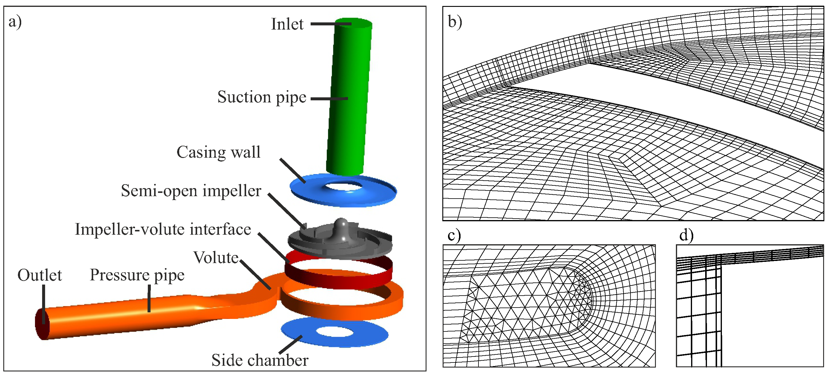
4.1. Test Case and Simulation Setup

A research pump with a semi-open impeller and 2D-blading, i.e., six cylindrical (non-twisted) blades, was investigated. The pump head H = Δ p / ρ w g + Δ z was evaluated by the static pressure and height difference Δ p and Δ z , respectively, between suction and pressure port. Beyond pump head and flow rate measurements, resulting in performance maps, according to Figure 1, high-speed visualization of the two-phase flow structures was performed by means of the scattered-light technique. Therefore, the impeller and the casing were manufactured from transparent acrylic glass to obtain optical access. Experiments were performed by Mansour et al. [26,27] at reduced rotational speed n = 650 1 / min to avoid damage of acrylic components. Details of the experiments are provided elsewhere [24,25,26,27,39,56,58,76], as well as in the accompanying experimental Part B of this review paper series.
The simulation domain is depicted in Figure 6a. A preferably realistic image of the real geometry was aimed at, so that the domain includes the impeller, suction and pressure pipe, volute casing, and side chamber. To capture the rotor–stator interaction and to account for any unsteady effects, unsteady pump simulations in the absolute frame of reference and with moving impeller mesh were performed, and the arbitrary mesh interface of Farrell and Maddison [157] was used. The SAS turbulence model, as described in Section 2.5, was applied. Velocity and pressure were prescribed as Dirichlet boundary conditions at the inlet and outlet of the computational domain, respectively. Dispersed air bubbles were assumed at the inlet, which were prescribed in terms of a Dirichlet condition for α φ and d B = 0.5 mm . The operation points considered in the simulation are indicated above in Figure 1. By having this range of operation conditions, all flow regimes from bubbly flow via agglomerated bubbles and alternating pocket flow to pure pocket flow were covered.
Particular care was taken for computational grid generation. By a grid refinement, first of all, the accuracy of the discretization scheme rose. At the same time, grid refinement also affected the turbulence and two-phase models. On the one hand, the turbulence scale-resolution capability of the SAS was enhanced, since turbulent fluctuations could be resolved down to the local grid resolution. On the other hand, successively finer void structures were resolved by the H2P solver, which transitioned towards a VoF-like scheme with phase–interface resolving capabilities. Thus, an inherent grid dependence of the results could not be avoided. What is more, the complex geometry of circumferential pumps required special care with regard to grid quality. For example, the meshing of round trailing edges or narrow gaps in semi-open impellers is particularly demanding [56,57,58]. Despite the considerable effort for grid generation, we prefer hexahedral cell grids wherever applicable due to their higher accuracy than, for example, triangular cells. Peculiarities of grid generation are provided in Refs. [56,57,58,76] and are not all repeated here. A grid study was performed, and the preferred computational grid, for which the results are presented further below, had about 16 Mio cells. A coarser version of the grid is shown in Figure 6b–d. Visually, smoothness and orthogonality appear to be poor. However, non-dimensional grid quality criteria, in terms of maximum non-orthogonality and minimum face volume ratio, were adopted from the OpenFOAM nomenclature [155] and indicated a fairly high quality, taking into account the complexity of the pump geometry. It was ensured that the conclusions drawn from the simulation results were not affected by grid dependence. Details of the simulation setup and the grid study are presented elsewhere [76].

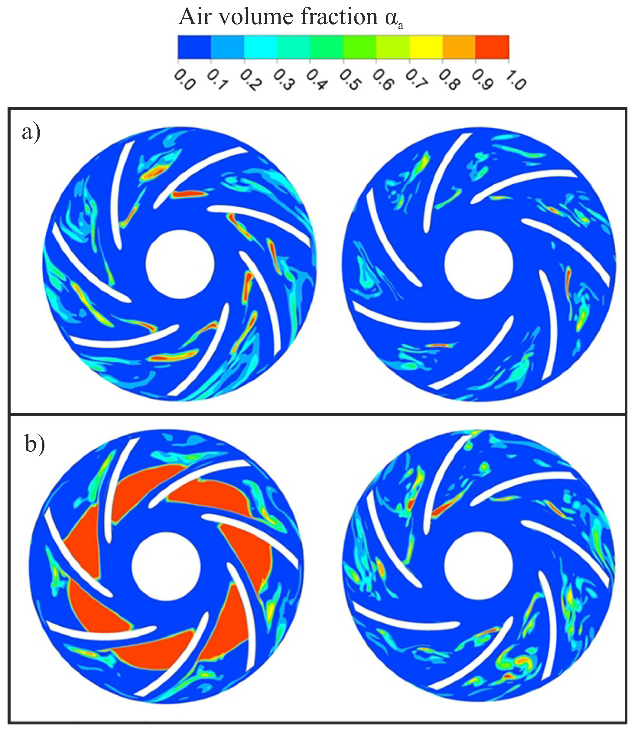
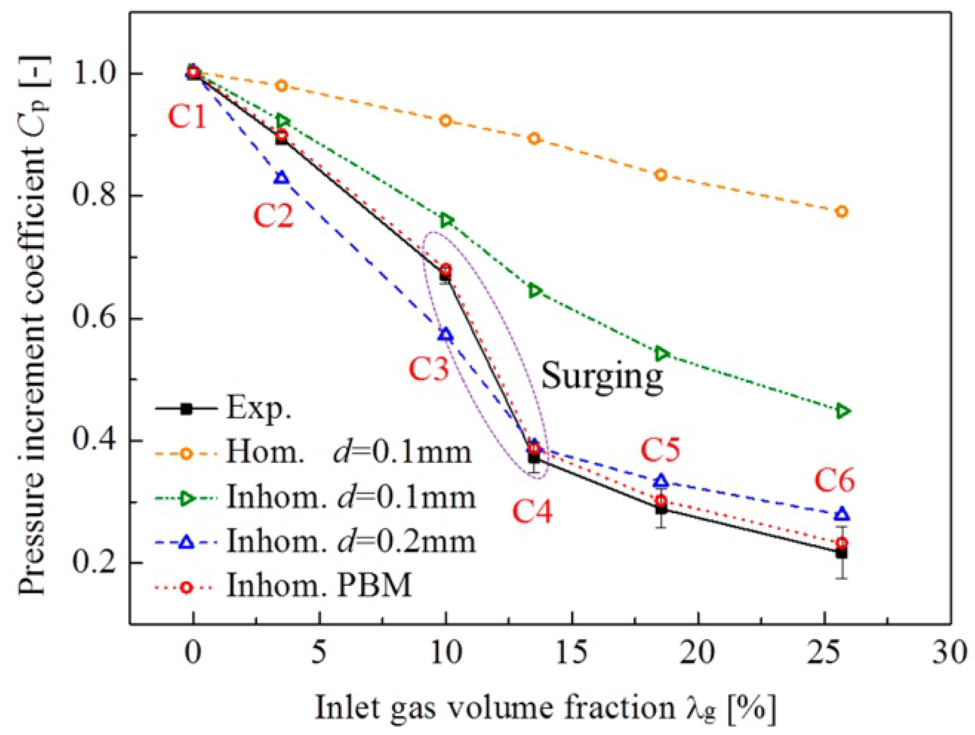
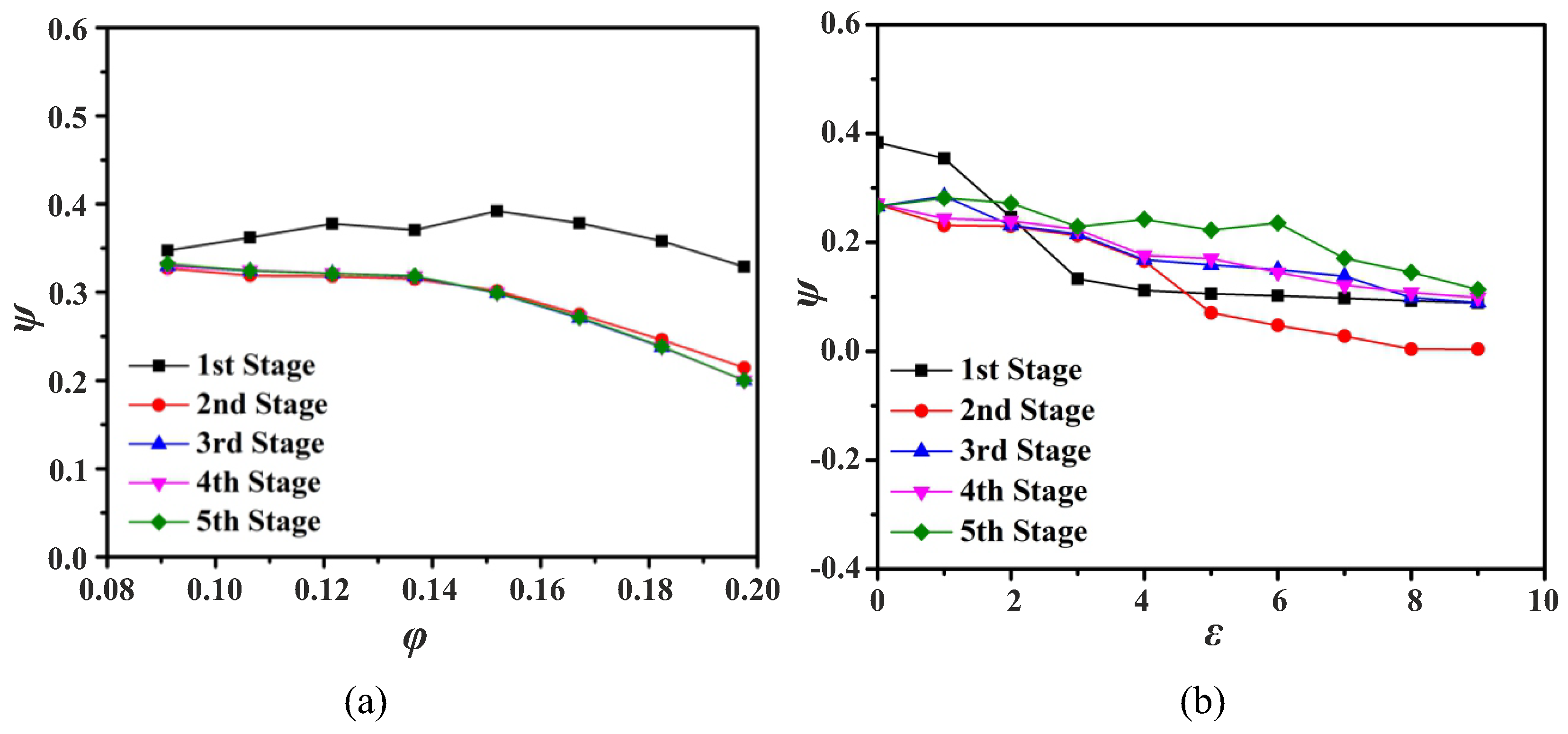
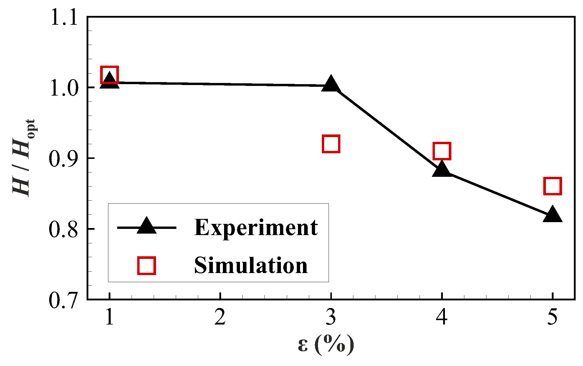
4.2. Selected Results

Selected results obtained by the H2P model in combination with the PBM are presented here. In Figure 7, the pump head drop by a rise of the inlet gas volume fraction ε is demonstrated. Albeit there were remaining differences to the experimental result, the trend was captured well at the first attempt. This is remarkable since, by means of a monodisperse ansatz, the predicted head level in the simulation can immediately be tuned to the experimental data by the prescribed bubble size d B [56,57,58]. In fact, for the applied grid resolution, a value of d B = 2.0 mm also yielded a reasonable head drop curve. Obviously, by using the PBM, a reasonable bubble size distribution was obtained without the need for tuning, which affected proper head drop characteristics. What is more, solver robustness was enhanced by the PBM, compared to the use of a constant value of d B , which we trace back to the fact that, in flow regions with small cell size, shear and, thus, bubble breakup were enhanced, and bubbles larger than the computational cells occurred less often.
The air accumulation is visualized in Figure 8a by means of the ensemble-averaged experimental results of a gray-scale analysis. With rising ε , air successively accumulated at the blade suction side, which, in turn, caused a head drop. Air accumulation was observable for ε = 1 % neither in the experimental nor in the simulation result. For ε = 3 % , the air started to agglomerate at the suction side of the blade. For ε = 4 % , the tendency of water and air to separate within the blade channel further increased. Air accumulations formed at the blade suction side near the leading edge. It is interesting that the accumulations were observable at every second blade in the simulation result. This behavior, in fact, reflects the alternating pocket flow regime, as discussed in detail by Hundshagen et al. [76]. For ε = 5 % , the air accumulations were attached at each blade and increased in size, which was, again, in good agreement with the experimentally observed trend. Summarizing, the size of air accumulations was captured well by the simulations, according to Figure 8b. Again, it should be pointed out that these accumulations developed without further tuning of the simulation parameters in terms of, for example, coalescence and breakup parameters.
Thus, from ε = 1 % to ε = 5 % , a transition from the bubbly flow regime over the agglomerated bubbles flow regime to the pocket flow regime was observed. In Figure 8c, the standard deviation of the air volume fraction, in terms of α a , RMS , is depicted. In the agglomerated bubbles flow regime for ε = 3 % , the bubble clustering was highly unsteady since the highest values of α a , RMS were observable in regions having the highest values of α a . In the alternating pocket flow regime at ε = 4 % , the air pocket, attached only at every second blade, was steady according to the low α a , RMS level within the attachment zone. At the other blades, local maxima of α a , RMS were present at the same blade location (as in the agglomerated bubbles flow regime at every blade), which, in fact, reflected the unsteady behavior of the alternating pocket flow regime. With a rising value of ε from ε = 3 % to ε = 5 % , the values of α a , RMS successively decreased in the region of air accumulations, which meant that the accumulations became more and more steady. The highest values of α a , RMS were present in the wake of the accumulations, which corresponded to the experimental observations of an unsteady wake and underlined the benefit of using a scale-resolving turbulence model.
In Figure 9a, the Sauter mean diameter d 32 of the bubbles is shown, and is, again, evaluated from the simulation results at mid-span. A cross-check to Figure 8b reveals that the location of large bubble diameter correlated with air accumulation zones, which meant that preferably large bubbles accumulated. A more detailed look at the coalescence kernel outcome (not shown here) showed high kernel activity in these regions, so that a self-energizing effect was present, leading to enforced growth of the accumulation. A look at the blending function C β , according to Equation (7), which is illustrated in Figure 9b, by an isosurface C β = 0.8 revealed that the H2P solver worked in a VoF-like mode in the accumulation regions. It is important to point out that by the transition of the solver towards VoF within the accumulation zones, the dispersed nature of the mixture had locally faded out, and the physical meaning of d B and, thus, d 32 degenerated. In fact, the diameter mutated into a purely numerical variable with a diminishing feedback to the local flow solution. It is interesting to note that no special means had to be applied to enhance solver stability in these flow situations. Thus, the air accumulations were treated in a reasonable way by a combination of an EE2F and VoF approach in terms of the H2P solver.

5. Conclusions

We have pointed out the limitations of recent approaches for the 3D simulation of liquid/gas flow in centrifugal pumps. On the one hand, the resolution of all phase interfaces by Volume-of-Fluid (VoF) methods is not feasible, so that this kind of approach is confined to the resolution of large coherent air accumulations. On the other hand, Euler–Euler Two-Fluid (EE2F) models treat dispersed bubbles on a subgrid level. Inspired by CFD approaches resulting from chemical and process engineering research [73,77,78,79,82,83,84,143,144,158,159], a hybrid method (H2P) is suggested, which is based on an EE2F scheme in most regions of the flow field, and transitions to VoF-like resolution, when air accumulations are detected. The H2P is combined with a population balance model (PBM) to capture bubble size distribution in flow regions with dispersed bubbles, i.e., where the H2P works in the pure EE2F mode. It was shown that coalescence activities correlate with air accumulations, which means that, in accumulation zones, bubbles grow by coalescence, leading to large air pockets. By means of this approach, the transition of flow regimes from bubbly to pocket flow detected in the experiments could, for the first time, be reproduced in 3D flow simulations. The importance of a scale-resolving turbulence approach to capture unsteady wakes downstream of the air pockets was shown. In spite of this quite promising first application of the H2P scheme to centrifugal pumps [76], and rather generic diffusor flows [140], improvements, for example in regard to blending functions, are suggested for future work. The PBM, particularly the breakup and coalescence kernels, have, so far, simply been adopted from completely different applications, such as bubble columns, and should be tailored for centrifugal pump flow applications in the future. In future studies, it should also be assessed if the H2P method, in fact, converges to a VoF solution with excessive grid refinement.

Author Contributions

Conceptualization, M.H. and R.S.; methodology, M.H. and R.S.; software, M.H.; investigation, M.H. and R.S.; writing—original draft preparation, M.H. and R.S.; writing—review and editing, M.H. and R.S.; supervision, R.S.; funding acquisition, R.S. All authors have read and agreed to the published version of the manuscript.

Funding

The research project was carried out in the framework of the industrial collective research program (IGF no. 20638 BG). It was supported by the Federal Ministry for Economic Affairs and Climate Action (BMWK) through the AiF (German Federation of Industrial Research Associations eV), based on a decision taken by the German Bundestag. Simulations of Section 4 were performed with computing resources granted by RWTH Aachen University under project bund0013.

Acknowledgments

We gratefully thank Michael Mansour and Dominique Thévenin (University of Magdeburg "Otto-von-Güricke") for providing the measurement data of the research pump. We also gratefully acknowledge Christian Hasse and Bich-Diep Nguyen (TU Darmstadt) for their valuable contribution to the hybrid solver development.

Conflicts of Interest

The authors declare no conflict of interest.

Nomenclature and Abbreviations

The following nomenclature is used in this manuscript:
Roman characters
a min , max , B Model constants for C α (-)
b min , max Model constants for C β (-)
c Velocity vector(m/s)
C α & C β Blending functions(-)
C D Drag coefficient(-)
C p Pressure increment coefficient(-)
dDiameter(m)
d 32 Sauter mean diameter(m)
HPump head(m)
kTurbulence kinetic energy(m2/s2)
MMomentum transfer terms(kg m/s2)
M s Surface tension force(kg m/s2)
nRotational speed(1/s)
n B Bubble number density function(1/m3)
pPressure(Pa)
QVolume flow rate(m3/s)
R e f f Effective stress tensor(kg m/s2)
V c Cell volume(m3)
Greek characters
α Volume fraction(-)
t Temporal derivative(1/s)
Δ Difference(-)
ε Inlet gas volume fraction(-)
κ Curvature(1/m)
λ g Inlet gas volume fraction(-)
Divergence operator(1/m)
ω Specific dissipation(1/s)
φ Flow coefficient(-)
ρ Density(kg/m3)
σ Surface tension factor(-)
Ψ Stage pressure coefficient(-)
Γ Constant(-)
Subscripts
aAir
BBubble
ExpExperimental result
mMixture
optOptimal
RMSStandard deviation
SimSimulation result
tTotal
wWater
φ Arbitrary phase
The following abbreviations are used in this manuscript:
3DThree-dimensional
C1 to C6Operation points in the study of Yan et al. [60]
CFDComputational fluid dynamics
DESDetached eddy simulation
DDESDelayed DES
EE2FEuler–Euler Two-Fluid
ESPElectrical submersible pump
GEMMAGeneralized multiphase modeling approach
H2PHybrid Two-Phase
Hom.Homogeneous
Inhom.Inhomogeneous
LESLarge-eddy simulation
MUSIGMulti-size group
PANSPartially-averaged Navier–Stokes
PBMPopulation balance modeling
PIMPLECombination of PISO and SIMPLE algorithm
PISOPressure Implicit with Splitting of Operators
PITMPartially-integrated transport model
SIMPLESemi-Implicit Pressure Method for Pressure Linked Equations
SASScale-adaptive simulation
SSTShear Stress transport
TVDTotal variation diminishing
URANSUnsteady Reynolds-averaged Navier Stokes
VoFVolume-of-Fluid

References

  1. Chan, A.; Kawaji, M.; Nakamura, H.; Kukita, Y. Experimental study of two-phase pump performance using a full size nuclear reactor pump. Nucl. Eng. Des. 1999, 193, 159–172. [Google Scholar] [CrossRef]
  2. Amoresano, A.; Langella, G.; Niola, V.; Quaremba, G. Advanced Image Analysis of Two-Phase Flow inside a Centrifugal Pump. Adv. Mech. Eng. 2014, 6. [Google Scholar] [CrossRef]
  3. Cappelino, C.A.; Roll, D.R.; Wilson, G. Design considerations and application guidelines for pumping liquids with entrained gas using open impeller centrifugal pump. In Proceedings of the 9th International Pump User Symposium, Houston, TX, USA, 24–27 September 2012; pp. 51–60. [Google Scholar] [CrossRef]
  4. Monte Verde, W.; Biazussi, J.L.; Sassim, N.A.; Bannwart, A.C. Experimental study of gas-liquid two-phase flow patterns within centrifugal pumps impellers. Exp. Therm. Fluid Sci. 2017, 85, 37–51. [Google Scholar] [CrossRef]
  5. Murakami, M.; Minemura, K. Effects of Entrained Air on the Performance of a Centrifugal Pump: 1st Report, Performance and Flow Conditions. Bull. JSME 1974, 17, 1047–1055. [Google Scholar] [CrossRef]
  6. Murakami, M.; Minemura, K.; Suehiro, H. Effects of entrained air on the performance of centrifugal and axial flow pumps. Mem. Fac. Eng. Kyushu Univ. 1971, 124–133. [Google Scholar]
  7. Furukawa, A.; Togoe, T.; Sato, S.; Takamatsu, Y. Fundamental studies on a tandem bladed impeller of gas/liquid two-phase flow centrifugal pump. Mem. Fac. Eng. Kyushu Univ. 1988, 48, 231–240. [Google Scholar] [CrossRef]
  8. Tillack, P. Förderverhalten von Kreiselpumpen bei viskosem, gasbeladenem Fördermedium. Ph.D. Thesis, Technical University Kaiserslautern, Kaiserslautern, Germany, 1998. [Google Scholar]
  9. Gülich, J.F. Centrifugal Pumps; Springer: Berlin/Heidelberg, Germany, 2010. [Google Scholar] [CrossRef]
  10. Sato, S.; Furukawa, A.; Takamatsu, Y. Air-water two-phase flow performance of centrifugal pump impellers with various blade angles. JSME Int. J., Ser. B 1996, 39, 223–229. [Google Scholar] [CrossRef]
  11. Zhu, J.; Zhang, H.Q. A Review of Experiments and Modeling of Gas-Liquid Flow in Electrical Submersible Pumps. Energies 2018, 11, 180. [Google Scholar] [CrossRef]
  12. Iben, U.; Wolf, F.; Freudigmann, H.A.; Fröhlich, J.; Heller, W. Optical measurements of gas bubbles in oil behind a cavitating micro-orifice flow. Exp. Fluids 2015, 56, 114. [Google Scholar] [CrossRef]
  13. Freudigmann, H.A.; Iben, U.; Pelz, P.F. Air release measurements of V-oil 1404 downstream of a micro orifice at choked flow conditions. J. Phys. Conf. Ser. 2015, 656, 12113. [Google Scholar] [CrossRef]
  14. Freudigmann, H.A.; Dörr, A.; Iben, U.; Pelz, P.F. Modeling of Cavitation-Induced Air Release Phenomena in Micro-Orifice Flows. ASME J. Fluids Eng. 2017, 139, 111301. [Google Scholar] [CrossRef]
  15. Kowalski, K.; Pollak, S.; Skoda, R.; Hussong, J. Experimental Study on Cavitation-Induced Air Release in Orifice Flows. ASME J. Fluids Eng. 2018, 140, 61201. [Google Scholar] [CrossRef]
  16. Frobenius, M.; Schilling, R.; Friedrichs, J.; Kosyna, G. Numerical and Experimental Investigations of the Cavitating Flow in a Centrifugal Pump Impeller. In Proceedings of the 2002 ASME Joint U.S.-European Fluids Engineering Conference, Montreal, QC, Canada, 14–18 July 2002; Rohatgi, U.S., Ed.; American Society of Mechanical Engineers: New York, NY, USA, 2002; pp. 361–368. [Google Scholar] [CrossRef]
  17. Limbach, P.; Kimoto, M.; Deimel, C.; Skoda, R. Numerical 3D Simulation of the Cavitating Flow in a Centrifugal Pump With Low Specific Speed and Evaluation of the Suction Head. In Proceedings of the ASME Turbo Expo 2014: Turbine Technical Conference and Exposition, Düsseldorf, Germany, 16–20 June 2014. [Google Scholar] [CrossRef]
  18. Limbach, P.; Müller, T.; Blume, M.; Skoda, R. Numerical and Experimental Investigation of the Cavitating Flow in a Low Specific Speed Centrifugal Pump and Assessment of the Influence of Surface Roughness on Head Prediction. In Proceedings of the International Symposium on Transport Phenomena and Dynamics (ISROMAC), Honululu, HI, USA, 10–15 April 2016. [Google Scholar]
  19. Limbach, P.; Skoda, R. Numerical and Experimental Analysis of Cavitating Flow in a Low Specific Speed Centrifugal Pump With Different Surface Roughness. ASME J. Fluids Eng. 2017, 139, 101201. [Google Scholar] [CrossRef]
  20. Liu, H.l.; Wang, J.; Wang, Y.; Zhang, H.; Huang, H. Influence of the empirical coefficients of cavitation model on predicting cavitating flow in the centrifugal pump. Int. J. Nav. Archit. Ocean Eng. 2014, 6, 119–131. [Google Scholar] [CrossRef]
  21. Shi, W.; Wang, C.; Wang, W.; Pei, B. Numerical Calculation on Cavitation Pressure Pulsation in Centrifugal Pump. Adv. Mech. Eng. 2014, 6, 367631. [Google Scholar] [CrossRef]
  22. Zhang, D.; Shi, W.; Pan, D.; Dubuisson, M. Numerical and Experimental Investigation of Tip Leakage Vortex Cavitation Patterns and Mechanisms in an Axial Flow Pump. ASME J. Fluids Eng. 2015, 137, 121103. [Google Scholar] [CrossRef]
  23. Mousmoulis, G.; Karlsen-Davies, N.; Aggidis, G.; Anagnostopoulos, J.; Papantonis, D. Experimental analysis of the onset and development of cavitation in a centrifugal pump. J. Phys. Conf. Ser. 2017, 813, 12044. [Google Scholar] [CrossRef]
  24. Mansour, M.; Wunderlich, B.; Thévenin, D. Effect of tip clearance gap and inducer on the transport of two-phase air-water flows by centrifugal pumps. Exp. Therm. Fluid Sci. 2018, 99, 487–509. [Google Scholar] [CrossRef]
  25. Mansour, M.; Wunderlich, B.; Thévenin, D. Experimental Study of Two-Phase Air/Water Flow in a Centrifugal Pump Working With a Closed or a Semi-Open Impeller. In Proceedings of the ASME Turbo Expo 2018: Turbine Technical Conference and Exposition, Oslo, Norway, 11–15 June 2018; The American Society of Mechanical Engineers: New York, NY, USA, 2018. [Google Scholar] [CrossRef]
  26. Mansour, M.; Parikh, T.; Thévenin, D. Influence of the shape of the impeller blade trailing edge on single and two-phase air water flows in a centrifugal pump. In Proceedings of the Turbomachinery & Pump Symposia, Houston, TX, USA, 13–16 December 2020. [Google Scholar]
  27. Mansour, M.; Kopparthy, S.; Thévenin, D. Investigations on the effect of rotational speed on the transport of air-water two-phase flows by centrifugal pumps. Int. J. Heat Fluid Flow 2022, 94, 108939. [Google Scholar] [CrossRef]
  28. Bieberle, A.; Schäfer, T.; Neumann, M.; Hampel, U. Validation of high-resolution gamma-ray computed tomography for quantitative gas holdup measurements in centrifugal pumps. Meas. Sci. Technol. 2015, 26, 95304. [Google Scholar] [CrossRef]
  29. Schäfer, T.; Bieberle, A.; Neumann, M.; Hampel, U. Application of gamma-ray computed tomography for the analysis of gas holdup distributions in centrifugal pumps. Flow Meas. Instrum. 2015, 46, 262–267. [Google Scholar] [CrossRef]
  30. Neumann, M.; Schäfer, T.; Bieberle, A.; Hampel, U. An Experimental Study on the Gas Entrainment in Horizontally and Vertically Installed Centrifugal Pumps. ASME J. Fluids Eng. 2016, 138, 12–19. [Google Scholar] [CrossRef]
  31. Schäfer, T.; Neumann, M.; Bieberle, A.; Hampel, U. Experimental investigations on a common centrifugal pump operating under gas entrainment conditions. Nucl. Eng. Des. 2017, 316, 1–8. [Google Scholar] [CrossRef]
  32. Schäfer, T.; Neumann-Kipping, M.; Bieberle, A.; Bieberle, M.; Hampel, U. Ultrafast X-Ray Computed Tomography Imaging for Hydrodynamic Investigations of Gas–Liquid Two-Phase Flow in Centrifugal Pumps. ASME J. Fluids Eng. 2020, 142, 41502. [Google Scholar] [CrossRef]
  33. Gambao, J.; Prado, M.G. Visualization study of performance breakdown in two-phase performance of an electrical submersible pump. In Proceedings of the Twenty-Sixth International Pump User Symposium, Houston, TX, USA, 26–28 September 2010. [Google Scholar] [CrossRef]
  34. Barrios, L.; Prado, M.G. Experimental Visualization of Two-Phase Flow Inside an Electrical Submersible Pump Stage. J. Energy Resour. Technol. 2011, 133, 42901. [Google Scholar] [CrossRef]
  35. Trevisan, F.E.; Prado, M. Experimental Investigation of the Viscous Effect on Two-Phase-Flow Patterns and Hydraulic Performance of Electrical Submersible Pumps. J. Can. Pet. Technol. 2011, 50, 45–52. [Google Scholar] [CrossRef]
  36. Shao, C.; Li, C.; Zhou, J. Experimental investigation of flow patterns and external performance of a centrifugal pump that transports gas-liquid two-phase mixtures. Int. J. Heat Fluid Flow 2018, 71, 460–469. [Google Scholar] [CrossRef]
  37. Stel, H.; Ofuchi, E.M.; Alves, R.F.; Chiva, S.; Morales, R.E.M. Experimental Analysis of Gas–Liquid Flows in a Centrifugal Rotor. ASME J. Fluids Eng. 2020, 142, 31101. [Google Scholar] [CrossRef]
  38. Zhao, L.; Chang, Z.; Zhang, Z.; Huang, R.; He, D. Visualization of gas-liquid flow pattern in a centrifugal pump impeller and its influence on the pump performance. Meas. Sensors 2021, 13, 100033. [Google Scholar] [CrossRef]
  39. Mansour, M.; Parikh, T.; Thévenin, D. Influence of Blade Pitch and Number of Blades of a Pump Inducer on Single and Two-Phase Flow Performance. In Proceedings of the ASME Turbo Expo 2020; Volume 9: Oil and Gas Applications; Organic Rankine Cycle Power Systems; Steam Turbine; The American Society of Mechanical Engineers: New York, NY, USA, 2020. [Google Scholar] [CrossRef]
  40. Si, Q.; Bois, G.; Zhang, K.; Yuan, J. Air-water two-phase flow experimental and numerical analysis in a low specific speed centrifugal pump. In Proceedings of the 12th European Turbomachinery Conference on Turbomachinery Fluid Dynamics & Thermodynamics, Stockholm, Sweden, 3–7 April 2017. [Google Scholar] [CrossRef]
  41. Si, Q.; Bois, G.; Jiang, Q.; He, W.; Ali, A.; Yuan, S. Investigation on the Handling Ability of Centrifugal Pumps under Air–Water Two-Phase Inflow: Model and Experimental Validation. Energies 2018, 11, 48. [Google Scholar] [CrossRef]
  42. Si, Q.; Bois, G.; Liao, M.; Zhang, H.; Cui, Q.; Yuan, S. A Comparative Study on Centrifugal Pump Designs and Two-Phase Flow Characteristic under Inlet Gas Entrainment Conditions. Energies 2020, 13, 65. [Google Scholar] [CrossRef]
  43. Si, Q.; Liao, M.; Fan, M.; Yuan, S.; Cui, Q.; Bois, G. Experimental study on flow behavior of unshrouded impeller centrifugal pumps under inlet air entrainment condition. In Proceedings of the 14th European Turbomachinery Conference on Turbomachinery Fluid Dynamics & Thermodynamics, Gdansk, Poland, 12–16 April 2021. [Google Scholar]
  44. Liao, M.; Si, Q.; Fan, M.; Wang, P.; Liu, Z.; Yuan, S.; Cui, Q.; Bois, G. Experimental Study on Flow Behavior of Unshrouded Impeller Centrifugal Pumps under Inlet Air Entrainment Condition. Int. J. Turbomach. Propuls. Power 2021, 6, 31. [Google Scholar] [CrossRef]
  45. Wan, Y.; Peters, N. Scaling of Spray Penetration with Evaporation. Atomiz. Spr. 1999, 9, 111–132. [Google Scholar] [CrossRef]
  46. Pak, E.T.; Lee, J.C. Performance and pressure distribution changes in a centrifugal pump under two-phase flow. Proc. Inst. Mech. Eng. A: J. Power Energy 1998, 212, 165–171. [Google Scholar] [CrossRef]
  47. Minemura, K.; Uchiyama, T. Prediction of Pump Performance Under Air-Water Two-Phase Flow Based on a Bubbly Flow Model. ASME J. Fluids Eng. 1993, 115, 781–783. [Google Scholar] [CrossRef]
  48. Müller, T.; Limbach, P.; Skoda, R. Numerical 3D RANS Simulation of Gas-Liquid Flow in a Centrifugal Pump with an Euler-Euler Two-Phase Model and a Dispersed Phase Distribution. In Proceedings of the 11th European Conference on Turbomachinery Fluid Dynamics & Thermodynamics, Madrid, Spain, 23–27 March 2015. [Google Scholar]
  49. Minemura, K.; Uchiyama, T. Three-Dimensional Calculation of Air-Water Two-Phase Flow in Centrifugal Pump Impeller Based on a Bubbly Flow Model. ASME J. Fluids Eng. 1993, 115, 766–771. [Google Scholar] [CrossRef]
  50. Caridad, J.; Asuaje, M.; Kenyery, F.; Tremante, A.; Aguillon, O. Characterization of a centrifugal pump impeller under two-phase flow conditions. J. Pet. Sci. Eng. 2008, 63, 18–22. [Google Scholar] [CrossRef]
  51. Yu, Z.Y.; Zhang, Q.Z.; Huang, R.; Cao, S.L. Numerical analysis of gas-liquid mixed transport process in a multiphase rotodynamic pump. IOP Conf. Ser. Earth Environ. Sci. 2012, 15, 32062. [Google Scholar] [CrossRef]
  52. Müller, T.; Limbach, P.; Skoda, R. Influence of Geometry Simplifications and Numerical Parameters in 3D URANS Liquid-Gas Flow Simulations of a Radial Pump with an Eulerian Mono-Dispersed Two-Phase Model. In Proceedings of the International Symposium on Transport Phenomena and Dynamics (ISROMAC), Honululu, HI, USA, 10–15 April 2016. [Google Scholar]
  53. Wang, B.; Zhang, H.; Deng, F.; Wang, C.; Si, Q. Effect of Short Blade Circumferential Position Arrangement on Gas-Liquid Two-Phase Flow Performance of Centrifugal Pump. Processes 2020, 8, 1317. [Google Scholar] [CrossRef]
  54. Zhou, L.; Han, Y.; Lv, W.; Yang, Y.; Zhu, Y.; Song, X. Numerical Calculation of Energy Performance and Transient Characteristics of Centrifugal Pump under Gas-Liquid Two-Phase Condition. Micromachines 2020, 11, 728. [Google Scholar] [CrossRef]
  55. Zhong, G.; Shao, C.; Cheng, W.; Zhao, Z. Numerical simulation and experimental study on gas–liquid two-phase unsteady flow in a centrifugal pump during the transition process. Proc. Inst. Mech. Eng. C: J. Mech. Eng. Sci. 2022, 236, 2224–2241. [Google Scholar] [CrossRef]
  56. Hundshagen, M.; Mansour, M.; Thévenin, D.; Skoda, R. Numerical investigation of two-phase air-water flow in a centrifugal pump with closed or semi-open impeller. In Proceedings of the 13th European Turbomachinery Conference on Turbomachinery Fluid Dynamics & Thermodynamics, Lausanne, Switzerland, 8–12 April 2019. [Google Scholar] [CrossRef]
  57. Hundshagen, M.; Mansour, M.; Thévenin, D.; Skoda, R. Experimental investigation and 3D-CFD simulation of centrifugal pumps for gasladen liquids with closed and semi-open impellers. In Proceedings of the 4th International Rotating Equipment Conference, Wiesbaden, Germany, 24–25 September 2019. [Google Scholar]
  58. Hundshagen, M.; Mansour, M.; Thévenin, D.; Skoda, R. 3D Simulation of Gas-Laden Liquid Flows in Centrifugal Pumps and the Assessment of Two-Fluid CFD Methods. Exp. Comput. Multiph. Flow 2021, 3, 186–207. [Google Scholar] [CrossRef]
  59. He, D.; Ge, Z.; Bai, B.; Guo, P.; Luo, X. Gas–Liquid Two-Phase Performance of Centrifugal Pump Under Bubble Inflow Based on Computational Fluid Dynamics–Population Balance Model Coupling Model. ASME J. Fluids Eng. 2020, 142, 81402. [Google Scholar] [CrossRef]
  60. Yan, S.; Sun, S.; Luo, X.; Chen, S.; Li, C.; Feng, J. Numerical Investigation on Bubble Distribution of a Multistage Centrifugal Pump Based on a Population Balance Model. Energies 2020, 13, 908. [Google Scholar] [CrossRef]
  61. Stel, H.; Ofuchi, E.M.; Chiva, S.; Morales, R.E. Numerical simulation of gas-liquid flows in a centrifugal rotor. Chem. Eng. Sci. 2020, 221, 115692. [Google Scholar] [CrossRef]
  62. Stel, H.; Ofuchi, E.M.; Chiva, S.; Morales, R.E.M. Numerical assessment of performance characteristics and two-phase flow dynamics of a centrifugal rotor operating under gas entrainment condition. Exp. Comput. Multiph. Flow 2021, 17, 221–240. [Google Scholar] [CrossRef]
  63. Zhang, F.; Zhu, L.; Chen, K.; Yan, W.; Appiah, D.; Hu, B. Numerical Simulation of Gas–Liquid Two-Phase Flow Characteristics of Centrifugal Pump Based on the CFD–PBM. Mathematics 2020, 8, 769. [Google Scholar] [CrossRef]
  64. Chen, Y.; Patil, A.; Chen, Y.; Bai, C.; Wang, Y.; Morrison, G. Numerical Study on the First Stage Head Degradation in an Electrical Submersible Pump With Population Balance Model. J. Energy Resour. Technol. 2019, 141. [Google Scholar] [CrossRef]
  65. Si, Q.; Asad, A.; Wang, B.; Wang, P.; Bois, G.; Jianping, Y.; Kubar, A.A. Numerical Study on Gas-Liquid Two Phase Flow Characteristic of Multistage Electrical Submersible Pump by Using a Novel Multiple-Size Group (MUSIG) Model. Phys. Fluids 2022, 34, 063311. [Google Scholar] [CrossRef]
  66. Mansour, M.; Kováts, P.; Wunderlich, B.; Thévenin, D. Experimental investigations of a two-phase gas/liquid flow in a diverging horizontal channel. Exp. Therm. Fluid Sci. 2018, 93, 210–217. [Google Scholar] [CrossRef]
  67. Kopparthy, S.; Mansour, M.; Janiga, G.; Thévenin, D. Numerical investigations of turbulent single-phase and two-phase flows in a diffuser. Int. J. Multiphase Flow 2020, 130, 103333. [Google Scholar] [CrossRef]
  68. Parikh, T.; Mansour, M.; Thévenin, D. Maximizing the performance of pump inducers using CFD-based multi-objective optimization. Struct. Multidisc. Optim. 2022, 65, 9. [Google Scholar] [CrossRef]
  69. Parikh, T.; Mansour, M.; Thévenin, D. Investigations on the effect of tip clearance gap and inducer on the transport of air-water two-phase flow by centrifugal pumps. Chem. Eng. Sci. 2020, 218, 115554. [Google Scholar] [CrossRef]
  70. Pineda, H.; Biazussi, J.; López, F.; Oliveira, B.; Carvalho, R.D.; Bannwart, A.C.; Ratkovich, N. Phase distribution analysis in an Electrical Submersible Pump (ESP) inlet handling water–air two-phase flow using Computational Fluid Dynamics (CFD). J. Pet. Sci. Eng. 2016, 139, 49–61. [Google Scholar] [CrossRef]
  71. Zhu, J.; Zhu, H.; Zhang, J.; Zhang, H.Q. A numerical study on flow patterns inside an electrical submersible pump (ESP) and comparison with visualization experiments. J. Pet. Sci. Eng. 2019, 173, 339–350. [Google Scholar] [CrossRef]
  72. Mansour, M.; Parikh, T.; Engel, S.; Thévenin, D. Numerical Investigations of Gas/Liquid Two-Phase Flow in a Pump Inducer. ASME J. Fluids Eng. 2020, 142, 21302. [Google Scholar] [CrossRef]
  73. de Santis, A.; Colombo, M.; Hanson, B.C.; Fairweather, M. A generalized multiphase modelling approach for multiscale flows. J. Comput. Phys. 2021, 436, 110321. [Google Scholar] [CrossRef]
  74. Hundshagen, M.; Rave, K.; Mansour, M.; Thévenin, D.; Skoda, R. Assessment of multi-phase CFD methods for gas-laden liquid flows in centrifugal pumps with particular emphasis on the change of flow morphology. In Proceedings of the 14th European Turbomachinery Conference on Turbomachinery Fluid Dynamics & Thermodynamics, Gdansk, Poland, 12–16 April 2021. [Google Scholar] [CrossRef]
  75. Marschall, H. Towards the Numerical Simulation of Multi-Scale Two-Phase Flows. Ph.D. Thesis, Technische Universität München, München, Germany, 2011. [Google Scholar]
  76. Hundshagen, M.; Rave, K.; Nguyen, B.D.; Popp, S.; Hasse, C.; Mansour, M.; Thévenin, D.; Skoda, R. Two-Phase Flow Simulations of Liquid/Gas Transport in Radial Centrifugal Pumps With Special Emphasis on the Transition From Bubbles to Adherent Gas Accumulations. ASME J. Fluids Eng. 2022, 144, 101202. [Google Scholar] [CrossRef]
  77. Hänsch, S.; Lucas, D.; Krepper, E.; Höhne, T. A multi-field two-fluid concept for transitions between different scales of interfacial structures. Int. J. Multiphase Flow 2012, 47, 171–182. [Google Scholar] [CrossRef]
  78. Hänsch, S.; Lucas, D.; Höhne, T.; Krepper, E. Application of a new concept for multi-scale interfacial structures to the dam-break case with an obstacle. Nucl. Eng. Des. 2014, 279, 171–181. [Google Scholar] [CrossRef]
  79. Meller, R.; Schlegel, F.; Lucas, D. Basic verification of a numerical framework applied to a morphology adaptive multifield two–fluid model considering bubble motions. Int. J. Numer. Meth. Fluids 2021, 93, 748–773. [Google Scholar] [CrossRef]
  80. Yin, J.; Zhang, T.; Krull, B.; Meller, R.; Schlegel, F.; Lucas, D.; Wang, D.; Liao, Y. A CFD approach for the flow regime transition in a vane-type gas-liquid separator. Int. J. Multiphase Flow 2023, 159, 104320. [Google Scholar] [CrossRef]
  81. Frederix, E.; Dovizio, D.; Mathur, A.; Komen, E. All-regime two-phase flow modeling using a novel four-field large interface simulation approach. Int. J. Multiphase Flow 2021, 145. [Google Scholar] [CrossRef]
  82. Wardle, K.E.; Weller, H.G. Hybrid Multiphase CFD Solver for Coupled Dispersed/Segregated Flows in Liquid-Liquid Extraction. Int. J. Chem. Eng. 2013, 2013, 128936. [Google Scholar] [CrossRef]
  83. Shonibare, O.Y.; Wardle, K.E. Numerical Investigation of Vertical Plunging Jet Using a Hybrid Multifluid–VOF Multiphase CFD Solver. Int. J. Chem. Eng. 2015, 2015, 925639. [Google Scholar] [CrossRef]
  84. Mathur, A.; Dovizio, D.; Frederix, E.; Komen, E. A Hybrid Dispersed-Large Interface Solver for multi-scale two-phase flow modelling. Nucl. Eng. Des. 2019, 344, 69–82. [Google Scholar] [CrossRef]
  85. Byskov, R.K.; Jacobsen, C.B.; Pedersen, N. Flow in a Centrifugal Pump Impeller at Design and Off-Design Conditions—Part II: Large Eddy Simulations. ASME J. Fluids Eng. 2003, 125, 73–83. [Google Scholar] [CrossRef]
  86. Kato, C.; Mukai, H.; Manabe, A. Large-Eddy Simulation of Unsteady Flow in a Mixed-Flow Pump. Int. J. Rotating Mach. 2003, 9, 345–351. [Google Scholar] [CrossRef]
  87. Tang, X.; Wang, F.; Wu, Y. An improved large eddy simulation of two-phase flows in a pump impeller. Acta Mech. Sin. 2007, 23, 635–643. [Google Scholar] [CrossRef]
  88. Tokyay, T.E.; Constantinescu, S.G. Validation of a Large-Eddy Simulation Model to Simulate Flow in Pump Intakes of Realistic Geometry. J. Hydraul. Eng. 2006, 132, 1303–1315. [Google Scholar] [CrossRef]
  89. Zhang, W.; Yu, Y.; Chen, H. Numerical Simulation of Unsteady Flow in Centrifugal Pump Impeller at Off-Design Condition by Hybrid RANS/LES Approaches. In High Performance Computing and Applications; Hutchison, D., Kanade, T., Kittler, J., Kleinberg, J.M., Mattern, F., Mitchell, J.C., Naor, M., Nierstrasz, O., Pandu Rangan, C., Steffen, B., et al., Eds.; Springer: Berlin/Heidelberg, Germany, 2010; Volume 5938, pp. 571–578. [Google Scholar] [CrossRef]
  90. Wang, W.; Wang, Y. Analysis of inner flow in low specific speed centrifugal pump based on LES. J. Mech. Sci. Technol. 2013, 27, 1619–1626. [Google Scholar] [CrossRef]
  91. Posa, A.; Lippolis, A.; Verzicco, R.; Balaras, E. Large-eddy simulations in mixed-flow pumps using an immersed-boundary method. Comput. Fluids 2011, 47, 33–43. [Google Scholar] [CrossRef]
  92. Posa, A.; Lippolis, A.; Balaras, E. Large-Eddy Simulation of a Mixed-Flow Pump at Off-Design Conditions. ASME J. Fluids Eng. 2015, 137, 49. [Google Scholar] [CrossRef]
  93. Si, Q.; Yuan, J.; Yuan, S.; Wang, W.; Zhu, L.; Bois, G. Numerical Investigation of Pressure Fluctuation in Centrifugal Pump Volute Based on SAS Model and Experimental Validation. Adv. Mech. Eng. 2014, 6, 972081. [Google Scholar] [CrossRef]
  94. Cui, B.; Zhang, C.; Zhang, Y.; Zhu, Z. Influence of Cutting Angle of Blade Trailing Edge on Unsteady Flow in a Centrifugal Pump Under Off-Design Conditions. Appl. Sci. 2020, 10, 580. [Google Scholar] [CrossRef]
  95. Shen, J.F.; Li, Y.J.; Liu, Z.Q.; Tang, X.L. Turbulent flow and pressure fluctuation prediction of the impeller in an axial-flow pump based on LES. IOP Conf. Ser.: Mater. Sci. Eng. 2013, 52, 032015. [Google Scholar] [CrossRef]
  96. Posa, A.; Lippolis, A.; Balaras, E. Investigation of Separation Phenomena in a Radial Pump at Reduced Flow Rate by Large-Eddy Simulation. ASME J. Fluids Eng. 2016, 138, 121101. [Google Scholar] [CrossRef]
  97. Posa, A.; Lippolis, A. A LES investigation of off-design performance of a centrifugal pump with variable-geometry diffuser. Int. J. Heat Fluid Flow 2018, 70, 299–314. [Google Scholar] [CrossRef]
  98. Posa, A.; Lippolis, A. Effect of working conditions and diffuser setting angle on pressure fluctuations within a centrifugal pump. Int. J. Heat Fluid Flow 2019, 75, 44–60. [Google Scholar] [CrossRef]
  99. Posa, A. LES investigation on the dependence of the flow through a centrifugal pump on the diffuser geometry. Int. J. Heat Fluid Flow 2021, 87, 108750. [Google Scholar] [CrossRef]
  100. Posa, A. LES study on the influence of the diffuser inlet angle of a centrifugal pump on pressure fluctuations. Int. J. Heat Fluid Flow 2021, 89, 108804. [Google Scholar] [CrossRef]
  101. Kye, B.; Park, K.; Choi, H.; Lee, M.; Kim, J.H. Flow characteristics in a volute-type centrifugal pump using large eddy simulation. Int. J. Heat Fluid Flow 2018, 72, 52–60. [Google Scholar] [CrossRef]
  102. Pacot, O.; Kato, C.; Guo, Y.; Yamade, Y.; Avellan, F. Large Eddy Simulation of the Rotating Stall in a Pump-Turbine Operated in Pumping Mode at a Part-Load Condition. ASME J. Fluids Eng. 2016, 138. [Google Scholar] [CrossRef]
  103. Zhang, N.; Liu, X.; Gao, B.; Wang, X.; Xia, B. Effects of modifying the blade trailing edge profile on unsteady pressure pulsations and flow structures in a centrifugal pump. Int. J. Heat Fluid Flow 2019, 75, 227–238. [Google Scholar] [CrossRef]
  104. Zhang, T.; Wu, D.; Qiu, S.; Zhou, P.; Ren, Y.; Mou, J. LES Analysis of the Unsteady Flow Characteristics of a Centrifugal Pump Impeller. Fluid Dyn. Mater. Process. 2022, 18, 1349–1361. [Google Scholar] [CrossRef]
  105. Zhou, P.; Dai, J.; Yan, C.; Zheng, S.; Ye, C.; Zhang, X. Effect of Stall Cells on Pressure Fluctuations Characteristics in a Centrifugal Pump. Symmetry 2019, 11, 1116. [Google Scholar] [CrossRef]
  106. Sorguven, E.; Incir, S.; Highgate, J. Understanding loss generation mechanisms in a centrifugal pump using large eddy simulation. Int. J. Heat Fluid Flow 2022, 96, 108994. [Google Scholar] [CrossRef]
  107. Pope, S.B. Turbulent Flows; Cambridge University Press: Cambridge, UK, 2000. [Google Scholar] [CrossRef]
  108. Fröhlich, J.; Mellen, C.P.; Rodi, W.; Temmermann, L.; Leschziner, M.A. Highly resolved large-eddy simulation of separated flow in a channel with streamwise periodic constrictions. J. Fluid Mech. 2005, 526, 19–66. [Google Scholar] [CrossRef]
  109. Kim, D.; Choi, H. Immersed boundary method for flow around an arbitrarily moving body. J. Comp. Phys. 2006, 212, 662–680. [Google Scholar] [CrossRef]
  110. Spalart, P.R.; Jou, W.H.; Strelets, M. Comments on the Feasibility of LES for Wings and on a Hybrid RANS/LES Approach. In Advances in DNS/LES; Liu, C., Liu, Z., Sakell, L., Eds.; Greyden Press: Columbus, OH, USA, 1997. [Google Scholar]
  111. Spalart, P.R. Detached-Eddy Simulation. Annu. Rev. Fluid Mech. 2009, 41, 181–202. [Google Scholar] [CrossRef]
  112. Spalart, P.R.; Deck, S.; Shur, M.L.; Squires, K.D.; Strelets, M.K.; Travin, A. A New Version of Detached-eddy Simulation, Resistant to Ambiguous Grid Densities. Theoret. Comput. Fluid Dynamics 2006, 20, 181–195. [Google Scholar] [CrossRef]
  113. Speziale, C.G. Turbulence Modeling for Time-Dependent RANS and VLES: A Review. AIAA J. 1998, 36, 173–184. [Google Scholar] [CrossRef]
  114. Basara, B.; Krajnovic, S.; Girimaji, S.; Pavlovic, Z. Near-Wall Formulation of the Partially Averaged Navier Stokes Turbulence Model. AIAA J. 2011, 49, 2627–2636. [Google Scholar] [CrossRef]
  115. Girimaji, S.S. Partially-Averaged Navier-Stokes Model for Turbulence: A Reynolds-Averaged Navier-Stokes to Direct Numerical Simulation Bridging Method. J. Appl. Mech. 2006, 73, 413–421. [Google Scholar] [CrossRef]
  116. Chaouat, B.; Schiestel, R. A new partially integrated transport model for subgrid-scale stresses and dissipation rate for turbulent developing flows. Phys. Fluids 2005, 17, 065106. [Google Scholar] [CrossRef]
  117. Xin, T.; Zhili, L.; Meng, Z.; Haotian, Y.; Wei, J.; Yuchuan, W.; Diyi, C. Analysis of Unsteady Flow Characteristics of Centrifugal Pump under Part Load Based on DDES Turbulence Model. Shock Vib. 2021, 2021, 1–11. [Google Scholar] [CrossRef]
  118. Zhang, N.; Liu, X.; Gao, B.; Xia, B. DDES analysis of the unsteady wake flow and its evolution of a centrifugal pump. Renew. Energy 2019, 141, 570–582. [Google Scholar] [CrossRef]
  119. Strelets, M. Detached eddy simulation of massively separated flows. In Proceedings of the 39th Aerospace Sciences Meeting and Exhibit; American Institute of Aeronautics and Astronautics: Reston, VA, USA, 2001. [Google Scholar] [CrossRef]
  120. Menter, F.; Carregal Ferreira, J.; Esch, T.; Konno, B. The SST Turbulence Model with Improved Wall Treatment for Heat Transfer Predictions in Gas Turbines. In Proceedings of the International Gas Turbine Congress, Tokyo, Japan, 2–7 November 2003. [Google Scholar]
  121. Gritskevich, M.S.; Garbaruk, A.V.; Schütze, J.; Menter, F.R. Development of DDES and IDDES Formulations for the k-$∖omega$ Shear Stress Transport Model. Flow Turbul. Combust. 2012, 88, 431–449. [Google Scholar] [CrossRef]
  122. Menter, F.; Hüppe, A.; Matyushenko, A.; Kolmogorov, D. An Overview of Hybrid RANS–LES Models Developed for Industrial CFD. Appl. Sci. 2021, 11, 2459. [Google Scholar] [CrossRef]
  123. Rotta, J.C. Turbulente Strömungen: Eine Einführung in die Theorie und ihre Anwendung; Vieweg+Teubner Verlag: Wiesbaden, Germany, 1972; Volume 15. [Google Scholar] [CrossRef]
  124. Fröhlich, J.; von Terzi, D. Hybrid LES/RANS methods for the simulation of turbulent flows. Prog. Aerosp. Sci. 2008, 44, 349–377. [Google Scholar] [CrossRef]
  125. Jakirlić, S.; Bopp, M.; Chang, C.Y.; Köhler, F.; Krumbein, B.; Kutej, L.; Kütemeier, D.; Maden, I.; Maduta, R.; Ullrich, M.; et al. RANS-based Sub-scale Modelling in Eddy-resolving Simulation Methods. ERCOFTAC Bull. 2019, 121, 5–16. [Google Scholar]
  126. Egorov, Y.; Menter, F. Development and Application of SST-SAS Turbulence Model in the DESIDER Project. In Advances in Hybrid RANS-LES Modelling; Peng, S.H., Haase, W., Eds.; Springer: Berlin/Heidelberg, Germany, 2008; Volume 97, pp. 261–270. [Google Scholar] [CrossRef]
  127. Menter, F. Two-equation eddy-viscosity turbulence models for engineering applications. AIAA J. 1994, 32, 1598–1605. [Google Scholar] [CrossRef]
  128. Menter, F.; Egorov, Y. The Scale-Adaptive Simulation Method for Unsteady Turbulent Flow Predictions. Part 1: Theory and Model Description. Flow Turbul. Combust. 2010, 85, 113–138. [Google Scholar] [CrossRef]
  129. Lucius, A.; Brenner, G. Unsteady CFD simulations of a pump in part load conditions using scale-adaptive simulation. Int. J. Heat Fluid Flow 2010, 31, 1113–1118. [Google Scholar] [CrossRef]
  130. Schiffer-Rosenberger, J.; Bodner, C.; Jaberg, H. Performance analysis of a single-blade impeller pump based on unsteady 3D numerical simulation. In Proceedings of the 3rd International Rotating Equipment Conference, Düsseldorf, Germany, 14–15 September 2016; pp. 193–203. [Google Scholar]
  131. Pavesi, G.; Dazin, A.; Cavazzini, G.; Caignaert, G.; Bois, G.; Ardizzon, G. Experimental and numerical investigation of unforced unsteadiness in a vaneless radial diffuser. In Proceedings of the 9th European Conference on Turbomachinery Fluid Dynamics & Thermodynamics, Istanbul, Turkey, 21–25 March 2011. [Google Scholar]
  132. Zhao, X.; Luo, Y.; Wang, Z.; Xiao, Y.; Avellan, F. Unsteady Flow Numerical Simulations on Internal Energy Dissipation for a Low-Head Centrifugal Pump at Part-Load Operating Conditions. Energies 2019, 12, 13. [Google Scholar] [CrossRef]
  133. Hundshagen, M.; Casimir, N.; Pesch, A.; Falsafi, S.; Skoda, R. Assessment of scale-adaptive turbulence models for volute-type centrifugal pumps at part load operation. Int. J. Heat Fluid Flow 2020, 85, 108621. [Google Scholar] [CrossRef]
  134. Rave, K.; Lehmenkühler, M.; Wirz, D.; Bart, H.J.; Skoda, R. 3D flow simulation of a baffled stirred tank for an assessment of geometry simplifications and a scale-adaptive turbulence model. Chem. Eng. Sci. 2021, 231, 116262. [Google Scholar] [CrossRef]
  135. Müller, T.; Limbach, P.; Skoda, R. 3D Liquid-Gas Flow Simulations of a Radial Pump with an Eulerian Mono-Dispersed Two-Phase Model. In Proceedings of the 3rd International Rotating Equipment Conference, Düsseldorf, Germany, 14–15 September 2016. [Google Scholar]
  136. Schiller, L.; Naumann, A. Über die grundlegenden Berechnungen bei Schwerkraftaufbereitung. Z. Des Vereines Dtsch. Ingenieure 1933, 77, 318–320. [Google Scholar]
  137. Auton, T.R.; Hunt, J.C.R.; Prud’Homme, M. The force exerted on a body in inviscid unsteady non-uniform rotational flow. J. Fluid Mech. 1988, 197, 241–257. [Google Scholar] [CrossRef]
  138. Rzehak, R.; Krepper, E.; Liao, Y.; Ziegenhein, T.; Kriebitzsch, S.; Lucas, D. Baseline Model for the Simulation of Bubbly Flows. Chem. Eng. Technol. 2015, 38, 1972–1978. [Google Scholar] [CrossRef]
  139. Brackbill, J.; Kothe, D.; Zemach, C. A continuum method for modeling surface tension. J. Comput. Phys. 1992, 100, 335–354. [Google Scholar] [CrossRef]
  140. Nguyen, B.D.; Popp, S.; Hundshagen, M.; Skoda, R.; Mansour, M.; Thévenin, D.; Hasse, C. Large Eddy Simulations of Turbulent Gas-Liquid Flows in a Diverging Horizontal Channel Using a Hybrid Multiphase Approach. ASME J. Fluids Eng. 2023, 145, 31501. [Google Scholar] [CrossRef]
  141. Blume, M.; Schwarz, P.; Rusche, H.; Weiß, L.; Wensing, M.; Skoda, R. 3D Simulation of Turbulent and Cavitating Flow for the Analysis of Primary Breakup Mechanisms in Realistic Diesel Injection Processes. Atomiz. Spr. 2019, 29, 861–893. [Google Scholar] [CrossRef]
  142. Ansys Inc. ANSYS CFX-Solver Theory Guide, Release 18.0; ANSYS, Inc.: Canonsburg, PA, USA, 2017. [Google Scholar]
  143. De Santis, A.; Hanson, B.C.; Fairweather, M. Hydrodynamics of annular centrifugal contactors: A CFD analysis using a novel multiphase flow modelling approach. Chem. Eng. Sci. 2021, 242, 116729. [Google Scholar] [CrossRef]
  144. Colombo, M.; de Santis, A.; Hanson, B.C.; Fairweather, M. Prediction of Horizontal Gas–Liquid Segregated Flow Regimes with an All Flow Regime Multifluid Model. Processes 2022, 10, 920. [Google Scholar] [CrossRef]
  145. Štrubelj, L.; Ťiselj, I. Two-fluid model with interface sharpening. Int. J. Numer. Meth. Eng. 2011, 85, 575–590. [Google Scholar] [CrossRef]
  146. Lo, S. Application of the MUSIG model to bubbly flows. In Proceedings of the AEAT-1096, AEA Technology, Carlsbad, CA, USA, June 1996. [Google Scholar]
  147. Krepper, E.; Frank, T.; Lucas, D.; Prasser, H.M.; Zwart, P. Inhomogeneous MUSIG model—A population balance approach for poly-dispersed bubbly flow. In Proceedings of the 6th International Conference on Multiphase Flow, Leipzig, Germany, 9–13 July 2007. [Google Scholar]
  148. Lehnigk, R.; Bainbridge, W.; Liao, Y.; Lucas, D.; Niemi, T.; Peltola, J.; Schlegel, F. An open–source population balance modeling framework for the simulation of polydisperse multiphase flows. AIChE J. 2022, 68, e17539. [Google Scholar] [CrossRef]
  149. Kumar, S.; Ramkrishna, D. On the solution of population balance equations by discretization—I. A fixed pivot technique. Chem. Eng. Sci. 1996, 51, 1311–1332. [Google Scholar] [CrossRef]
  150. Krepper, E.; Lucas, D.; Frank, T.; Prasser, H.M.; Zwart, P.J. The inhomogeneous MUSIG model for the simulation of polydispersed flows. Nucl. Eng. Des. 2008, 238, 1690–1702. [Google Scholar] [CrossRef]
  151. Prince, M.J.; Blanch, H.W. Bubble coalescence and break-up in air-sparged bubble columns. AIChE J. 1990, 36, 1485–1499. [Google Scholar] [CrossRef]
  152. Luo, H.; Svendsen, H.F. Theoretical model for drop and bubble breakup in turbulent dispersions. AIChE J. 1996, 42, 1225–1233. [Google Scholar] [CrossRef]
  153. Liao, Y.; Rzehak, R.; Lucas, D.; Krepper, E. Baseline closure model for dispersed bubbly flow: Bubble coalescence and breakup. Chem. Eng. Sci. 2015, 122, 336–349. [Google Scholar] [CrossRef]
  154. Rave, K.; Hermes, M.; Wirz, D.; Hundshagen, M.; Friebel, A.; von Harbou, E.; Bart, H.J.; Skoda, R. Experiments and fully transient coupled CFD-PBM 3D flow simulations of disperse liquid-liquid flow in a baffled stirred tank. Chem. Eng. Sci. 2022, 253, 117518. [Google Scholar] [CrossRef]
  155. Jasak, H. Error Analysis and Estimation for the Finite Volume Method with Applications to Fluid Flows. Ph.D. Thesis, Imperial College of Science, Technology and Medicine, London, UK, 1996. [Google Scholar]
  156. Patankar, S.; Spalding, D. A calculation procedure for heat, mass and momentum transfer in three-dimensional parabolic flows. Int. J. Heat Mass Transfer 1972, 15, 1787–1806. [Google Scholar] [CrossRef]
  157. Farrell, P.E.; Maddison, J.R. Conservative interpolation between volume meshes by local Galerkin projection. Comput. Methods Appl. Mech. Eng. 2011, 200, 89–100. [Google Scholar] [CrossRef]
  158. Černe, G.; Petelin, S.; Ťiselj, I. Coupling of the Interface Tracking and the Two-Fluid Models for the Simulation of Incompressible Two-Phase Flow. J. Comp. Phys. 2001, 171, 776–804. [Google Scholar] [CrossRef]
  159. Noroozi, M.M.; Maddahian, R.; Ramezani, M.H.; Ansari, M.R. An LES-Like Multiscale Multiphase Flow Model Based on Break-up and Coalescence Phenomena. J. Appl. Fluid Mech. 2022, 15, 1073–1085. [Google Scholar] [CrossRef]
Figure 2. Development of air accumulations, calculated by the coupled EE2F–PBM model (left) and the monodisperse EE2F model (right) for ε = 2.21 % (a) and ε = 4.86 % (b) at n = 1500 1 / min and Q = 7.7 m 3 / h . The figure is adopted from He et al. [59].
Ijtpp 08 00015 g002
Figure 3. Pressure coefficient versus inlet gas volume fraction for different EE2F model variants and experimental data. The figure is adopted from Yan et al. [60].
Ijtpp 08 00015 g003
Figure 4. Simulation results of the stage performance in terms of head coefficient Ψ for (a) pure water versus the flow coefficient φ and for (b) two-phase flow conditions at φ = 0.152 versus the inlet gas volume fraction ε . The figure is adapted from Si et al. [65].
Ijtpp 08 00015 g004
Figure 5. Instantaneous air distribution within a semi-open impeller for a variation of the inlet gas volume fraction ε : experimental images (bottom row) and numerical results of VoF simulations (top row). In the simulations, isosurfaces for α a > 0.05 are shown. The figure is adapted from Parikh et al. [69].
Ijtpp 08 00015 g005
Figure 6. Explosion view of the computational domain (a). Detailed view of the impeller grid near the blade trailing edge at midspan (b), in the tip clearance gap at the leading edge from axial view direction (c), and in the tip clearance gap from radial view direction (d).
Ijtpp 08 00015 g006
Figure 7. Normalized pump head H versus inlet gas volume fraction ε . Experimental values are taken from Mansour et al. [27,39].
Ijtpp 08 00015 g007
Figure 8. Air distribution in the impeller: ensemble-averaged experimental results of a gray-scale analysis (a). Time-averaged air volume fraction at impeller midspan (b) and its standard deviation (c), obtained from simulation results.
Ijtpp 08 00015 g008
Figure 9. Contour plots at impeller midspan for the time-averaged Sauter mean diameter d 32 (a) and isosurfaces of a blending function threshold value C β = 1.0 (b).
Ijtpp 08 00015 g009
Disclaimer/Publisher’s Note: The statements, opinions and data contained in all publications are solely those of the individual author(s) and contributor(s) and not of MDPI and/or the editor(s). MDPI and/or the editor(s) disclaim responsibility for any injury to people or property resulting from any ideas, methods, instructions or products referred to in the content.

