Article

Readily Accessible M-Ferrocenyl-Phenyl Sulfonate as Novel Cathodic Electrolyte for Aqueous Organic Redox Flow Batteries

Institute of Rare and Scattered Elements, College of Chemistry, Liaoning University, Shenyang 110036, China
*
Author to whom correspondence should be addressed.
Batteries 2023, 9(5), 285; https://doi.org/10.3390/batteries9050285
Submission received: 24 March 2023 / Revised: 25 April 2023 / Accepted: 20 May 2023 / Published: 22 May 2023
(This article belongs to the Special Issue Promising Redox Flow Batteries)

Abstract

:
Ferrocene derivatives are amongst the most promising electroactive organic electrolytes. The bottleneck problems of their application in aqueous redox flow batteries are their poor solubility and lower potential as well as the complexity of the modification methods to solve these problems. In this study, a benzenesulfonic acid group is easily introduced into the ferrocene structure by a mature diazotization reaction, and the synthesized sodium m-phenylferrocene sulfonate BASFc is used as the novel cathodic electroactive electrolyte for AORFB. The hydrophilicity and the electron-absorbing effect of the introduced benzenesulfonic group can effectively improve the water solubility and redox potential of ferrocene. Moreover, the introduction of phenyl extends the conjugated structure of ferrocene and increases its structural dimension, which may be conducive to reducing its membrane permeability and improving the structural stability to some extent. The physical structure and the electrochemical properties of BASFc are studied systematically; the feasibility of its application as a cathodic electrolyte in AORFBs is verified by assembling the half-cell and full-cell. The results verify the good electrochemical reaction kinetics of BASFc in acid electrolyte and the corresponding AORFB shows satisfactory efficiency and stability.

1. Introduction

Renewable energies, such as solar and wind energy, play a vital role in promoting social and economic development. However, due to the inherent intermittency of these renewable energies, direct grid connection is not easily achieved. Therefore, the development of large-scale energy storage technology has become a hot topic in the international community [1,2,3]. Redox flow batteries (RFBs) have the unique merit of decoupled power generation and energy storage, which allow more flexible regulation of capacity and power, and have become a kind of most preferred technology for scale energy storage [4,5,6].
Vanadium redox flow batteries (VRFBs) are the most popular member of RFBs, though the low abundance of vanadium electroactive reactant limits its large-scale and sustainable application [7,8,9,10]. Organic compounds as redox active species possess refined structural adjustability and high abundance—the redox potential and solubility can be adjusted by introducing specific functional groups into the organic molecules’ structure. In recent years, aqueous organic redox flow batteries (AORFBs) have attracted much attention [11,12,13,14,15]. Quinone, flavin, alizarin, alloxazine, phenazine and viologen have been widely developed as anodic active materials [11,16,17,18,19,20]. Cathodic active materials are relatively less well developed, mainly including derivatives of ferrocene, ferrocyanide, hydroquinone, phenothiazine and 2,2,6,6-tetramethylpiperidine (TEMPO) [20,21,22,23,24].
Ferrocene (Fc), which was first discovered in 1951, is probably the most well-known and best understood “sandwich” complex consisting of Fe(II) and two cyclopentadienyl ligands [25,26]. Ferrocene derivatives possess excellent electrochemical redox activity, and are widely used in redox flow batteries. However, most ferrocene derivatives show lower solubility in water, which limits the energy density of the battery and has hindered their feasibility of application. Water-soluble ferrocene derivatives have become a research focus as cathodic active materials in AORFBs, with their water solubility and redox potential being the main targets of research. The introduction of an electron-withdrawing group, such as trimethylammonium [11,27] and sulfonate [20,28,29,30], may effectively improve the cathodic potential, and hydrophilic groups, such as hydroxyl [12,13], carboxy [31] and phosphate [32] may help to increase the solubility. Furthermore, the existence of certain substituents may increase steric effects and improve the structural stability of the redox-active ferrocene [27].
Hydrophilic quaternary ammonium groups are commonly applied to promote the water solubility of ferrocene organic electrolytes, with the solubility and redox potential being related to the structure and substituting position of the functional group [11,12,27,33]. Hu [11] synthesized FcNCl, which possessed a solubility of 4 M in water. The capacity retention ratio of the AORFB with 0.5M FcNCl as the cathodic electrolyte and 0.5 M MV as the anode electrolyte remained at 91% after 700 cycles at 60 mA/cm2, while the Coulomb efficiency remained above 99% and the voltage efficiency and energy efficiency were both 60%. Eugene [27] developed a bis(trimethylammoniopropyl) functionalized ferrocene, which evidenced ~2 M solubility in water and the corresponding AORFB showed high cycle stability. The capacity retention rate was 99.9989%/cycle or 99.967%/day with an average Coulomb efficiency greater than 99.9%. Introducing sulfonic groups into the ferrocene structure was also an effective way to improve its solubility and potential. Yu [29] directly introduced a sulfonic acid group into the cyclopentadienyl of ferrocene (Fc-SO3Na); the AORFB, with 1.5 M Fc-SO3Na solution as the catholyte and Zn as the anode, exhibited a capacity retention of 97.5% after 1000 cycles (99.9975% per cycle). Zhang [34] synthesized two amphoteric ferrocenes (Fc3 and Fc4) with different chain lengths. Both quaternary ammonium groups and sulfonic acid groups were introduced to increase their solubility; their solubility in water was 0.66 M and 2.01 M, and the redox potential of Fc3 and Fc4 was 0.456 V and 0.453 V (vs. Ag/AgCl), respectively. Taking a 2,7-anthraquinone-disulfonic acid sodium salt as the negative active electrolyte and 1 M NaNO3 as the supporting electrolyte, Fc4 obtained a high Coulomb efficiency of over 99% and voltage efficiency and energy efficiency over 80%, while Fc3 had an energy efficiency of 88% at a current density of 2.5 mA/cm2. Fc4 showed better stability with a capacity decay rate of about 1%/day, which was significantly lower than the 3%/day of Fc3. Moreover, the introduction of substituents was able to significantly increase the size exclusion and, thus, suppressed reactant crossover through the membrane. However, due to the difficult activation of cyclopentadiene in the ferrocene structure, the synthesis conditions of ferrocene sulfonate derivatives are quite harsh, often requiring the use of dangerous chemicals with high activity, such as sulfonyl chloride [35].
Herein, sodium m-benzenesulfonate ferrocene (BASFc) was synthesized by the simple and mature diazotization reaction to synergistically optimize the water solubility and redox potential of ferrocene by introducing a phenyl sulfonate group with preferable hydrophilicity and electron-absorbing properties. As a result, the synthetic BASFc possessed a solubility of nearly 1.0 M in H2SO4 aqueous solution and the redox potential shifted positively by almost 69 mV. Moreover, it showed excellent electrochemical reactivity and reversibility in acidic and pH-neutral aqueous solution. The full cell with BASFc as the cathode, V3+ as the anode and H2SO4 as the supporting electrolyte could achieve a Coulomb efficiency of nearly 100% and an energy efficiency of more than 70% at 60 mA/cm−2, and the capacity retention was about 87.64% after 120 cycles.

2. Experimental Section

2.1. Materials and Reagents

All chemicals were purchased from commercial vendors and used without further purification. All experiments were conducted at atmospheric pressure. Ferrocene (≥99.0%), sodium nitrite (≥99.0%), sodium sulphate (≥99.0%) and sodium hydroxide (99.0%) were purchased from DAMAO (Tianjin, China). Acetic acid (99.5%) was purchased from the Fuyu Fine chemical company. 3-aminobenzene sulfonic acid (98%) was purchased from Macklin (Shanghai, China).

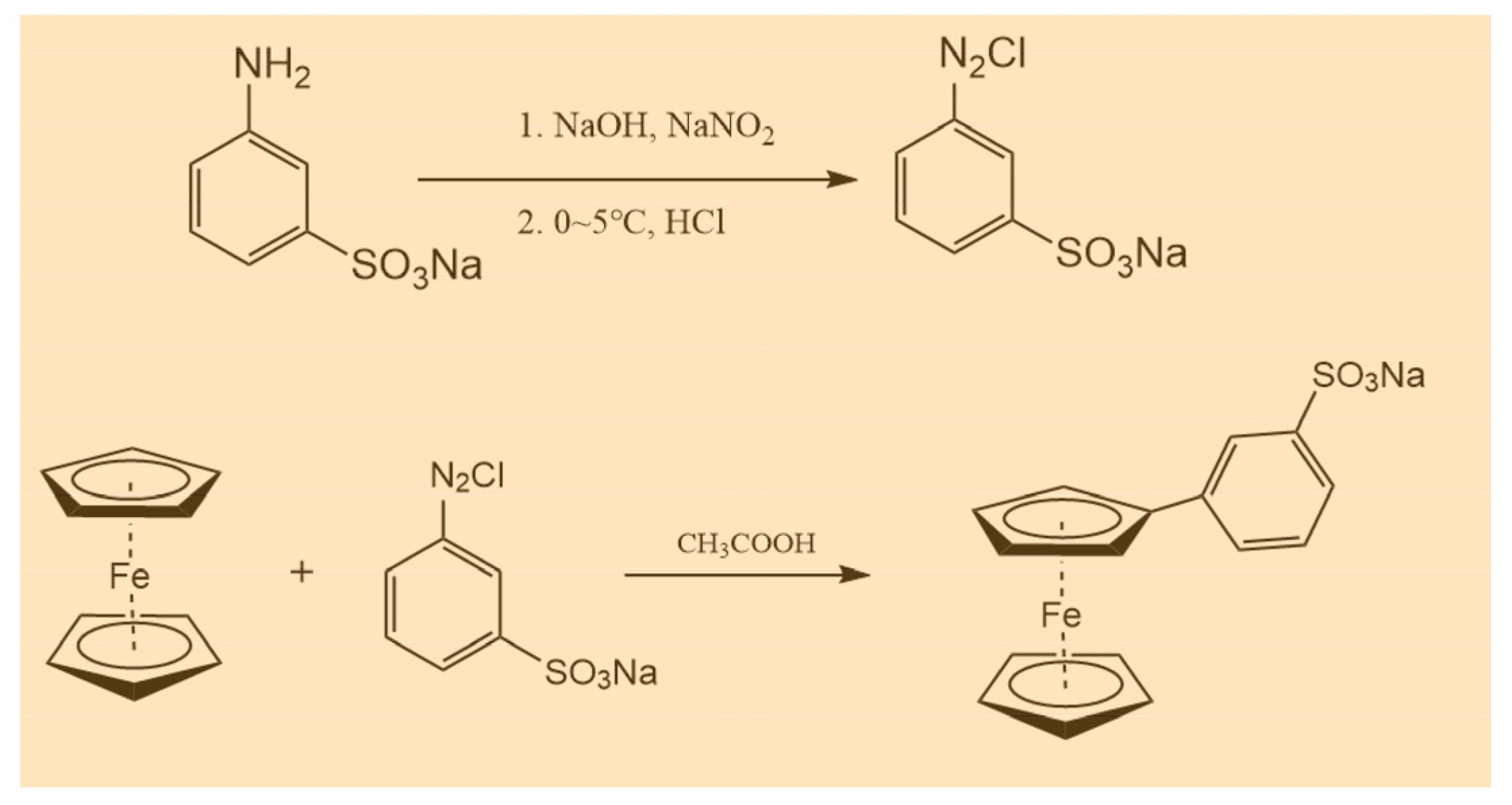
2.2. Synthesis of Sodium M-Benzenesulfonate Ferrocene (BASFc)

The sodium m-benzenesulfonate ferrocene (BASFc) was synthesized by a simple and mature diazotization reaction. The specific synthesis process was as follows: 3-aminobenzenesulfonic acid (1.73 g, 10 mmol) was dissolved in 10 mL 5 wt.% NaOH aqueous solution, then 10 mL of aqueous solution containing NaNO2 (0.759 g, 0.01 mol) was added and the mixed solution was stirred thoroughly in an ice water bath. The mixed solution with 3 mL concentrated HCl and 10 mL water was added dropwise to the above reaction mixture; it was let stand for about 15 min after dropping. The mixture obtained above was added into the solution of ferrocene (1.86 g, 10 mmol) in acetic acid (70 mL), then stirred at ambient temperature for 16 h. The pH was adjusted to neutral with 40 wt.% NaOH to precipitate the target product, which was filtered and recrystallized with 5 wt.% NaOH aqueous solution, then washed with CH2Cl2 three times, with pure BASFc obtained: BASFc, 2.5 g, 68.7% yield. 1H-NMR (500 MHz, D2O): δ7.80 (q, 4H), δ4.37 (d, 4H), δ3.97(s, 5H). The synthesis route is shown in Scheme 1.

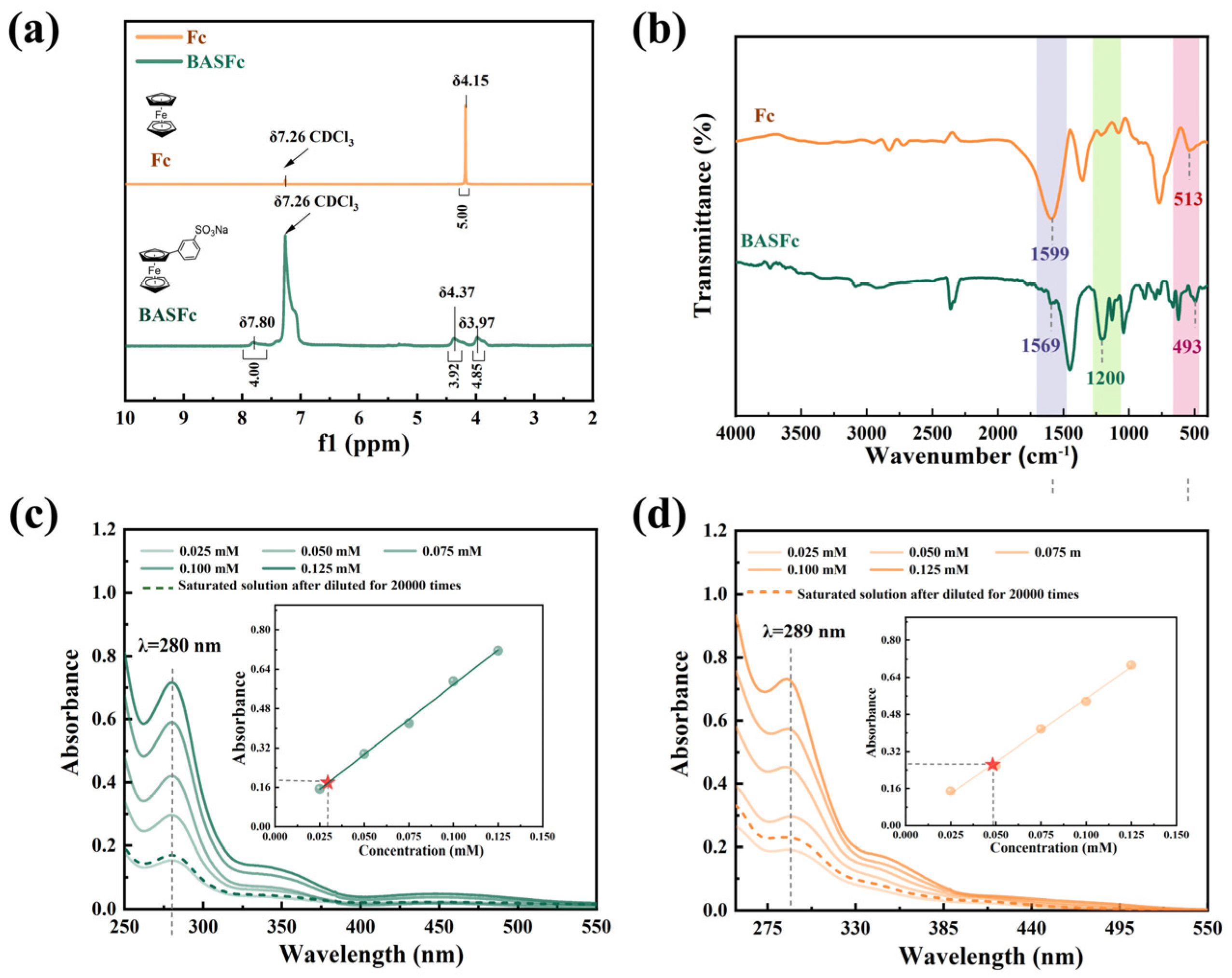
2.3. Physical Characterization

The structure and composition of the synthetic products were investigated systematically. 1H-NMR spectra were collected using a Bruker 500 MHz NMR spectrometer with deuterated chloroform (CDCl3) (7.26 ppm for 1H-NMR) as the internal standard. Fourier transform infrared spectroscopy spectra were tested on an IR-Prestige21 instrument in the range of 400~4000 cm−1 using a KBr pellet as the blank. The UV-vis absorption spectra were recorded on a Lambda 35 spectrophotometer to calculate the solubility of the synthetic products. The relationship between the concentration and absorbance was established at the wave peaks of 280 and 289 nm. The oversaturated solutions were achieved by adding excess BASFc into 500 μL water (or 0.5 M Na2SO4 or 1.0 M H2SO4); the upper clear liquid was sucked through a 100μL pipette gun to give a homogeneous saturated solution. Subsequently, the saturated solution was diluted and then tested by UV-vis; the saturated solution concentration could be calculated with the established standard curve. Each solution was measured at least three times. The surface morphology and element composition of the battery diaphragm before and after charging and discharging were investigated by SEM-EDS technology.

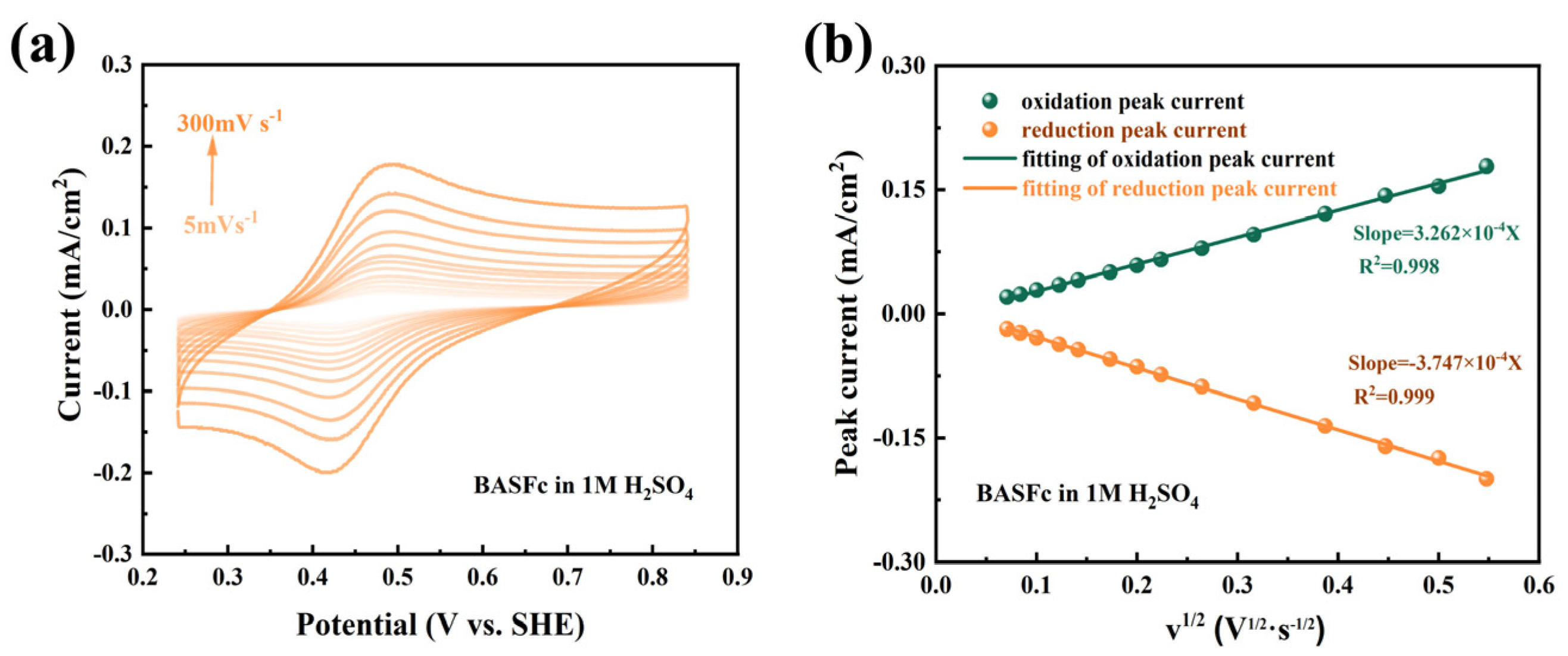
2.4. Electrochemical Characterization

CV measurements were conducted by a common three-electrode system, in which a saturated calomel electrode was used as the reference electrode, a platinum sheet (1.5 × 1.5 cm) was used as the assistant electrode and a glassy carbon electrode (GCE) (3 mm diameter) and graphite plate (1 × 1 cm) were used as the working electrode. Before each test, the GCE working electrode was polished with 0.05 um alumina powder, cleaned with ultrasonic washer in water, rinsed with ethanol and blow-dried with N2.

2.5. Flow Battery Tests

The half-cell and full-cell RFBs were constructed with a neutral electrolyte (0.5 M Na2SO4 as supporting electrolyte) or an acidic electrolyte (1 M H2SO4 as supporting electrolyte) by sandwiching a Nafion 212 membrane or a homemade PBI membrane [36] with two pieces of carbon felt electrodes (1.5 × 1.5 cm). The circulation of the electrolyte was controlled by a peristaltic pump at a flow rate of 24.26 mL/min.

3. Results and Discussions

First, the structures of the synthesized BASFc and the unsubstituted ferrocene were characterized by 1H-NMR spectra. As shown in Figure 1a, the peak at δ7.8 belonged to the hydrogen on the benzene ring. The peak at δ3.97 was attributed to the hydrogen on the unsubstituted cyclopentadiene ring of BASFc, while the δ value moved to the lower field (δ4.37) after the substitution of the benzene sulfonic acid group, which could be attributed to the reduced electron cloud density and the enhanced deshielded effect due to the electron absorption effect of the benzenesulfonate group. By comparison, there was only one type of H (δ4.15) on the pristine unsubstituted ferrocene, which was the H on the cyclopentadiene ring. The IR spectra of ferrocene and BASFc were as shown in Figure 1b. The absorption peak located at 513 cm−1 in the IR spectrum of the unsubstituted Fc corresponded to the coordination bond of FeII-Cp in ferrocene [33], which shifted to 493 cm−1 when the benzenesulfonic acid group was introduced on the Cp ring, indicating that the coordination intensity between FeII and the substituted Cp in BASFc was weaker than that of the unsubstituted Fc. This might be ascribed to the stronger electron-absorbing effect of the benzenesulfonic acid group and the conjugation extension of benzene, and Cp reducing the electron cloud density of the Cp and resulting in a weaker coordination bond with the central FeII. The stronger peak at 1200 cm−1 corresponded to the sulfonic group in BASFc. The peak at 1599 cm−1 corresponded to C=C of the Cp in ferrocene, while the peak position shifted to 1569 cm−1 after substitution in BASFc due to the extended conjugation effect. Figure 1c–d show the UV-vis spectra of BASFc in pure H2O and 1 M H2SO4 aqueous solution with different concentrations. The bands at 341 nm and 447 nm belonged to the two spin-allowed d-d transitions of the monosubstituted ferrocene in water [33], while the peak at 447 nm shifted to 422 nm in 1 M H2SO4, which might have been caused by the formed ion pairs and hydrogen bonding. The strong absorption around 289 nm could be assigned to the overlapped metal-to-ligand charge transfer (MLCT) and ligand-to-metal charge transfer (LMCT) [37]. Furthermore, the solubility of BASFc in various solutions was determined by UV-vis measurements, being 0.985 M in 1 M H2SO4 and 0.595 M in water. In addition, the solubility of BASFc in 0.5 M Na2SO4 aqueous solution was only 0.095 M (Figure S1). The storage stability of the solution at room temperature was poor; flocculent precipitation could be observed after two days at room temperature, which might have been due to the competitive mechanism generated by the same cation in BASFc and Na2SO4. The results suggest that the BASFc exhibited higher solubility and stability in H2SO4 aqueous solution, which might be related to the formed ion pairs in acid solution [38] and the sulfuric acid solution of BASFc being more suitable as the electrolyte in the AORFBs. Furthermore, the larger spatial structure of the organic electroactive molecules made it more difficult to pass through the diaphragm channels, effectively reducing the cross-contamination of the positive and negative electrolytes [27].
The electrochemical properties of 0.5 mM BASFc and saturated Fc in 1 M H2SO4 aqueous solution were investigated by CV tests at 100 mV/s. As shown in Figure 2a, the current response of the saturated solution of pristine ferrocene was very weak because of its extremely low solubility in water. Furthermore, the redox potential of BASFc shifted nearly 69 mV positively compared to that of ferrocene due to the electron-drawing effect of the benzene sulfonic group, which improved the potential window and energy density of the ferrocene-based AORFBs. Moreover, the stability of 5 mM BASFc in acidic electrolytes was investigated by 50 consecutive cyclic voltammetry scans at 100 mV/s. As shown in Figure 2b–c, no obvious current attenuation or peak shift occurred in the CV curves after 50 cycles of continuous scanning, suggesting good stability of BASFc in the acidic electrolyte. In Figure S2, the redox potential of 0.5 mM BASFc in 0.5 M Na2SO4 shifted 32 mV positively compared to that of the saturated ferrocene solution, and good electrochemical stability of BASFc in low concentration in 0.5 M Na2SO4 was also observed.
The electrochemical reaction kinetics of 0.5 mM BASFc in 1M H2SO4 were further investigated by cyclic voltammetry at different scan rates. As shown in Figure 3a, the peak position and peak separation were nearly unchanged as the scan rate increased from 5 mV·s−1 to 300 mV·s−1, suggesting fast electron transfer kinetics and excellent redox reversibility of BASFc. A linear relationship between the peak current and the square root of the scan rate was clearly observed in Figure 3b, which indicated that the electrochemical redox reactions were controlled by the diffusion process. The diffusion coefficient (D) and electrode reaction rate constant (k0) were also calculated by the Randles–Savcik Equation (1) and Nicholson’s Equation (2).
i p = 2.69 × 10 5 × n 3 2 × D 1 2 × v 1 2 × C × A
k 0 = π × D × f × v 1 2 × Ψ
where n is the electron transfer number, A is the electrode area (cm2), D is the diffusion coefficient (cm2·s−1), v is the scan rate (V·s−1) and Ψ is calculated by the well-known fitting Equation (3).
Ψ = 0.6288 + 0.0021 n Δ E p 1 0.017 n Δ E p
where ΔEp is the peak potential separation (V).
As a result, the diffusion coefficient D was calculated to be 2.64 × 10⁻⁶ cm2/s and the electrode reaction rate constant k0 to be 5.50 × 10⁻³ cm/s. The same experiment was carried out in 0.5 M Na2SO4; the results are shown in Figure S3. While the D value was 2.78 × 10⁻⁶ cm2/s and k0 was 5.64 × 10⁻³ cm/s in 0.5 M Na2SO4, both values were similar to those in 1M H2SO4. Comparison of the kinetic parameters in other work is provided and tabulated in Table S1 [12,27,29,30,32,39,40,41]. The BASFc synthesized in this work possessed satisfactory electrochemical reaction kinetics compared with other ferrocene derivatives, suggesting that the introduction of a large conjugated benzenesulfonic group had no obvious effect on the electrochemical reaction kinetics of ferrocene.
Furthermore, the feasibility of application of BASFc as the active electrolyte in acidic AORFBs was studied, firstly by constructing a symmetrical half-cell using 0.01 M BASFc(Fe(Ⅲ)/(Fe(Ⅱ)) and 1 M H2SO4 aqueous solution as both the cathodic and anodic electrolytes. Figure 4a shows the charge-discharge curves of the flowing half-cell at a current density of 60 mA/cm2 for the 2nd and 120th cycles. Figure 4b shows the discharge capacity during the 120 continuous charge and discharge cycles. The capacity attenuation was obvious in the first half of the 120 cycles, but flattened out during the last half of the cycles due to the equilibrium of the positive and negative electrolytes [42]. The discharge capacity attenuation rate was about 0.179% per cycle, which was a satisfactory attenuation rate for the ferrocene-based flow batteries. The same situation happened under pH-neutral conditions (Figure S4a,b), with the retention rate of the battery capacity being 0.121%. We tested the cyclic voltammetry of the electrolyte before and after charging-discharging. As shown in Figure 4c and Figure S4c, after the charge-discharge cycle, the peak position of the CV curve did not change significantly, and no other peaks appeared, but the current response slightly decreased, which might have been caused by the mass loss of active substances, such as irreversible deposition on the diaphragm and porous electrode.
Finally, a full-cell with 0.3 M BASFc as the cathode, 0.3 M V2+/V3+ as the anode and 1 M H2SO4 as the supporting electrolyte was constructed to preliminarily inspect the application potential of BASFc (Figure 5a). The theoretical voltage window of the acid BASFc/V AORFB was about 0.71 V, as shown in the CV curves of Figure 5b. Figure 5c shows the charging-discharging curves at current densities of 20, 40, 60 and 80 mA/cm2. With increase in the current density, the polarization overpotential obviously increased, and the corresponding charge-discharge capacity gradually decreased. The battery efficiencies under different current densities are shown in Figure 5d. The Coulomb efficiencies of the cell at different current densities were all nearly 100%. The EE and VE were both over 70% at a current density of 60 mA/cm2, which indicates the potential application performance of BASFc. However, the cell efficiencies were influenced by the combination of the key materials, such as the diaphragm, electrode and electrolyte—the new electrolyte needed to be matched with the appropriate electrode and diaphragm materials for better performance, which would be one of the future priorities to address. For comparison, a full-cell with 3 mM BASFc as the cathode, Zn2+/Zn as the anode and 0.5 M Na2SO4 as the supporting electrolyte was constructed to study the application performance of BASFc under neutral conditions (Figure S5a). It was found that the cell efficiency was relatively higher, and the capacity attenuation was mitigated, when the concentration of BASFc was lower in the pH-neutral electrolyte condition (Figure S5b–d).
In order to further investigate the cycling stability and the cause of capacity attenuation of the battery, 120 continuous charge and discharge tests at 60 mA/cm2 were carried out. As shown in Figure 6a, in the first dozen cycles, the discharge capacity attenuation showed a relatively flat trend, but then suddenly decreased significantly. The capacity nearly recovered after the addition of 0.2 mL (1.5 M V2++ 1M H2SO4) negative electrolyte, and then this situation appeared again when the charge and discharge had gone through about the 60th cycle. This indicated that the loss of reduced anodic electrolyte in the negative tank due to the chemical oxidation of V2+ by oxygen led to an imbalance in the positive and negative electrolytes, which was the main reason for the rapid capacity attenuation, while the positive BASFc electrolyte was relatively stable. As a result, a capacity retention of 87.64% after 120 cycles was obtained, suggesting satisfactory stability of the full-cell through appropriate control of the charge-discharge processes. Figure 6b shows the change trend in the battery efficiencies during 120 cycles. The CE was nearly 100% when the battery was in a stable state; thus, the values of VE and EE were almost the same. The VE and EE of the battery showed similar attenuation to the charging and discharge capacity, which recovered somewhat after the addition of the negative electrolyte, indicating again that the limiting side of the battery performance was the anode. However, even with the addition of the anodic electrolyte, the capacity and effi-ciency also declined, suggesting that the loss of the cathodic electrolyte was also on-going, though to a lesser extent than that of the anodic electrolyte.
In order to explore the degree of, and reason for, the cathodic and anodic attenuation, we investigated the CV of the electrolytes and the composition of the membrane before and after charging and discharging. As shown in Figure 6c, the current response of the BASFc cathode and the V anode both decreased to a certain extent. Moreover, the small redox peaks belonging to the opposite side were detected in both the positive and negative electrolytes, indicating that there was a crossover between the cathode and anode, but that the amount was quite small. SEM-EDS analysis was conducted on both sides of the PBI membrane after continuous charge and discharge. As shown in Figure 6d, vanadium was detected to a slight extent on the side in contact with the positive electrolyte, while both iron and vanadium were detected on the side in contact with the negative electrolyte, indicating that BASFc was more easily adsorbed and transmitted through the membrane than vanadium. The AORFB with 3 mM BASFc + 0.5 M Na2SO4 as the cathode and Zn plate + 1 M ZnSO4 as the anode showed decreased attenuation of the battery efficiencies and capacity due to the pH-neutral electrolyte and the lower concentration of electroactive material, as shown in Figure S5c,d. The CE and EE of the pH-neutral AORFB were about 99.8% and 83.3% at a current density of 20 mA/cm2, respectively. In future work, emphasis will be placed on research into matched anolyte, membrane and supporting electrolyte materials to further improve the practical application performance of BASFc.

4. Conclusions

In summary, a benzenesulfonic group with conjugated expansion and electron-absorbing effects was introduced into the Cp rings of the insoluble ferrocene by simple and mature diazotization. The obtained BASFc species possessed a higher solubility of 0.985 M in 1M H2SO4 and the redox potential shifted by nearly 69 mV compared to the unsubstituted ferrocene due to the strong polarity and electron-absorbing effect of the introduced benzenesulfonic group. In addition, BASFc exhibited comparable electrochemical reaction kinetics with other ferrocene-based active electrolytes. As a result, the full-cell, with 0.3 M BASFc as the cathode, 0.3 M V3+ as the anode and 1 M H2SO4 as the supporting electrolyte, could achieve a Coulomb efficiency of nearly 100% and an energy efficiency of more than 70% at 60 mA/cm2, with a capacity retention of about 87.64% after 120 cycles of continuous charging and discharging. Therefore, BASFc appears to be a novel type of cathode electrolyte for AORFBs due to its simple and safe synthesis method, cheap raw material price, high solubility and relatively positive potential. However, the attenuation mechanism of battery performance needs further study, and matching diaphragm and electrode materials need to be investigated in detail in future work to further improve battery performance.

Supplementary Materials

The following supporting information can be downloaded at: https://www.mdpi.com/article/10.3390/batteries9050285/s1. Figure S1. Photos of 10 mM BASFc in 0.5M Na2SO4 aqueous solution atfer 3 days(a) UV spectrum and concentration standard curve of BASFc in 0.5M Na2SO4 (b); Figure S2. CV curves of saturated Fc and 0.5 mM BASFc in 0.5 M Na2SO4 (a) CV curves for 50 consecutive cycles (b) and peak current attenuation with the number of scans in 0.5M Na2SO4 (c); Figure S3. CV curves at different scan rates(a) of 0.5 mM BASFc and the linear relationship between the peak current and the square root of scan rate in 0.5M Na2SO4 (b); Figure S4. Charge-discharge curves for the flow battery with 10 mM BASFc + 0.5 M Na2SO4 (10 mL) as cathode and anode at 5 mA cm−2 of 2nd and 150th cycles (a) Curve of charge-discharge capacitance attenuation of the cell at 1 mA cm−2 during 150 continuous charge and discharge cycles(b) CV curves of the positive BASFc electrolyte before and after charging-discharging(c); Figure S5. CV curves of 3 mM BASFc and zinc in 0.5M Na2SO4 (18 mL) (a) Charge-discharge curves for the flow battery with 3 mM BASFc + 0.5 M Na2SO4 (18mL) as cathode and Zn plate in 1M ZnSO4 (18 mL) as anode at 5 mA cm−2 of 2nd and 100th cycles (b) CE, VE and EE (c) of the cell at 10 mA cm−2 during 100 continuous charge and discharge cycles; CV curves of the positive BASFc electrolyte before and after charging-discharging; Table S1. Electrochemical kinetics data of BASFc and other ferrocene derivatives in aqueous solutions. References [12,27,29,30,33,38,39,40] are cited in the Supplementary Materials part.

Author Contributions

D.F.: conceptualization, resources, writing—original draft, funding acquisition; J.Z.: investigation, validation, writing—original draft; X.L.: investigation, validation; D.W.: validation, investigation, writing—original drafts; Y.Y.: investigation, validation; Z.L.: validation; Z.S.: funding acquisition; M.J.: conceptualization, resources; writing—review and editing, funding acquisition. All authors have read and agreed to the published version of the manuscript.

Funding

This research was funded by the Department of Science and Technology of Liaoning Province (CN) (No.2020-BS-079; No. 2022-BS-115), the Project of Education Department of Liaoning Province(LJKMZ20220445; LJKZZ20220018), the National Natural Science Foundation of China (No.22173039), the Liaoning BaiQianWan Talents Program (2017), the Liaoning Revitalization Talents Program (XLYC1807197), the Key Technologies R & D Program of the Liaoning Provincial Department of Education (LZD201906), the Program for Liaoning Innovative Research Team in University (LT2019006), and the Project of the Central Government in Guidance of Local Science and Technology Development (2020JH6/10500003).

Data Availability Statement

The data presented in this study are available on request from the corresponding author.

Conflicts of Interest

The authors declare no conflict of interest.

References

  1. Dunn, B.; Kamath, H.; Tarascon, J.M. Electrical energy storage for the grid: A battery of choices. Science 2011, 334, 928–935. [Google Scholar] [CrossRef] [PubMed]
  2. Goodenough, J.B.; Park, K.S. The Li-ion rechargeable battery: A perspective. J. Am. Chem. Soc. 2013, 135, 1167–1176. [Google Scholar] [CrossRef] [PubMed]
  3. Yang, Z.; Zhang, J.; Kintner-Meyer, M.C.; Lu, X.; Choi, D.; Lemmon, J.P.; Liu, J. Electrochemical Energy Storage for Green Grid. Chem. Rev. 2011, 111, 3577–3613. [Google Scholar] [CrossRef] [PubMed]
  4. Nguyen, T.; Savinell, R.F. Flow Batteries. Electrochem. Soc. Interface 2010, 19, 54–56. [Google Scholar]
  5. Skyllas-Kazacos, M.; Chakrabarti, M.H.; Hajimolana, S.A.; Mjalli, F.S.; Saleem, M. Progress in Flow Battery Research and Development. J. Electrochem. Soc. 2011, 158, R55. [Google Scholar] [CrossRef]
  6. Weber, A.Z.; Mench, M.M.; Meyers, J.P.; Ross, P.N.; Gostick, J.T.; Liu, Q.H. Redox flow batteries: A review. J. Appl. Electrochem. 2011, 41, 1137–1164. [Google Scholar] [CrossRef]
  7. Soloveichik, G.L. Flow Batteries: Current Status and Trends. Chem. Rev. 2015, 115, 11533–11558. [Google Scholar] [CrossRef]
  8. Winsberg, J.; Hagemann, T.; Janoschka, T.; Hager, M.D.; Schubert, U.S. Redox-Flow Batteries: From Metals to Organic Redox-Active Materials. Angew. Chem. Int. Ed. 2017, 56, 686–711. [Google Scholar] [CrossRef]
  9. Li, X.; Zhang, H.; Mai, Z.; Zhang, H.; Vankelecom, I. Ion exchange membranes for vanadium redox flow battery (VRB) applications. Energy Environ. Sci. 2011, 4, 1147–1160. [Google Scholar] [CrossRef]
  10. Jiang, H.; Sun, J.; Wei, L.; Wu, M.; Shyy, W.; Zhao, T. A High Power Density and Long Cycle Life Vanadium Redox Flow Battery. Energy Storage Mater. 2020, 24, 529–540. [Google Scholar] [CrossRef]
  11. Hu, B.; Debruler, C.; Rhodes, Z.; Liu, T. A Long Cycling Aqueous Organic Redox Flow Battery (AORFB) towards Sustainable and Safe Energy Storage. J. Am. Chem. Soc. 2017, 139, 1207–1214. [Google Scholar] [CrossRef] [PubMed]
  12. Chen, Q.; Li, Y.; Liu, Y.; Sun, P.; Yang, Z.; Xu, T. Designer Ferrocene Catholyte for Aqueous Organic Flow Batteries. ChemSusChem 2021, 14, 1295–1301. [Google Scholar] [CrossRef] [PubMed]
  13. Liu, W.; Liu, Y.; Zhang, H.; Xie, C.; Shi, L.; Zhou, Y.; Li, X. A highly stable neutral viologen/bromine aqueous flow battery with high energy and power density. Chem. Commun. 2019, 55, 4801–4804. [Google Scholar] [CrossRef]
  14. Jin, S.; Fell, E.M.; Vina-Lopez, L.; Jing, Y.; Michalak, P.W.; Gordon, R.G.; Aziz, M.J. Near Neutral pH Redox Flow Battery with Low Permeability and Long-Lifetime Phosphonated Viologen Active Species. Adv. Energy Mater. 2020, 10, 2000100. [Google Scholar] [CrossRef]
  15. DeBruler, C.; Hu, B.; Moss, J.; Liu, X.; Luo, J.; Sun, J. Designer Two-Electron Storage Viologen Anolyte Materials for Neutral Aqueous Organic Redox Flow Batteries. Chem 2017, 3, 961–978. [Google Scholar] [CrossRef]
  16. Huskinson, B.; Marshak, M.P.; Suh, C.; Er, S.; Gerhardt, M.R.; Galvin, C.J.; Cheng, X.; Aspuru-Guzik, A.; Gordon, R.G.; Aziz, M.J. A metal-free organic–inorganic aqueous flow battery. Nature 2014, 505, 195–198. [Google Scholar] [CrossRef] [PubMed]
  17. Lin, K.; Gomez-Bombarelli, R.; Beh, E.S.; Tong, L.; Chen, Q.; Valle, A.; Aspuru-Guzik, A.; Azjz, M.J.; Gordon, R.G. A redox-flow battery with an alloxazine-based organic electrolyte. Nat. Energy 2016, 1, 16102. [Google Scholar] [CrossRef]
  18. Orita, A.; Verde, M.G.; Sakai, M.; Meng, Y. A biomimetic redox flow battery based on flavin mononucleotide. Nat. Commun. 2016, 7, 13230. [Google Scholar] [CrossRef]
  19. Hollas, A.; Wei, X.; Murugesan, V.; Nie, Z.; Li, B.; Reed, D.; Liu, J.; Sprenkle, V.; Wang, W. A biomimetic high-capacity phenazine-based anolyte for aqueous organic redox flow batteries. Nat. Energy 2018, 3, 508–514. [Google Scholar] [CrossRef]
  20. Li, H.; Fan, H.; Hu, B.; Hu, L.; Chang, G.; Song, J. Spatial Structure Regulation: A Rod-Shaped Viologen Enables Long Lifetime in Aqueous Redox Flow Batteries. Angew. Chem. Int. Ed. 2021, 60, 26971–26977. [Google Scholar] [CrossRef]
  21. Zhao, Z.; Zhang, B.; Schrage, B.R.; Ziegler, C.J.; Boika, A. Investigations into Aqueous Redox Flow Batteries Based on Ferrocene Bisulfonate. ACS Appl. Energy Mater. 2020, 3, 10270–10277. [Google Scholar] [CrossRef]
  22. Zhang., C.; Niu, Z.; Peng, S.; Ding, Y.; Zhang, L.; Guo, X.; Zhao, Y. Phenothiazinebased organic catholyte for high-capacity and long-life aqueous redox flow batteries. Adv. Mater. 2019, 31, 1901052. [Google Scholar] [CrossRef] [PubMed]
  23. Park, M.; Beh, E.S.; Fell, E.M.; Jing, Y.; Kerr, E.F.; Porcellinis, D.D.; Goulet, M.; Ryu, J.; Wong, A.A.; Gordon, R.G.; et al. A high voltage aqueous zinc–organic hybrid flow battery. Adv. Energy Mater 2019, 9, 1900694. [Google Scholar] [CrossRef]
  24. Nambafu, G.S.; Siddharth, K.; Zhang, C.; Zhao, T.; Chen, Q.; Amine, K.; Shao, M. An organic bifunctional redox active material for symmetric aqueous redox. Nano Energy 2021, 89, 106422. [Google Scholar] [CrossRef]
  25. Miller, S.A.; Tebboth, J.A.; Tremaine, J.F. Dicyclopentadienyliron. J. Chen. Soc. 1952, 632–635. [Google Scholar] [CrossRef]
  26. Kealu, T.J.; Pauson, P.L. A new type of organo-iron compound. Nature 1951, 168, 1039. [Google Scholar] [CrossRef]
  27. Beh, E.S.; Porcellinis, D.D.; Gracia, R.L.; Xia, K.T.; Gordon, R.G.; Aziz, M.J. A Neutral pH Aqueous Organic/Organometallic Redox Flow Battery with Extremely High Capacity Retention. ACS Energy Lett. 2017, 2, 639–644. [Google Scholar] [CrossRef]
  28. Yang, H.; Chen, X.; Jiang, W.; Lu, Y. Convenient synthesis of new water-soluble monosubstituted functional ferrocene derivatives. Inorg. Chem. Commun. 2005, 8, 853–857. [Google Scholar] [CrossRef]
  29. Yu, J.; Salla, M.; Zhang, H.; Ji, Y.; Zhang, F.; Zhou, M.; Wang, Q. A robust anionic sulfonated ferrocene derivative for pH-neutral aqueous flow battery. Energy Storage Mater. 2020, 29, 216–222. [Google Scholar] [CrossRef]
  30. Yao, Y.; Xu, H.; Tian, Z.; Zhang, J.; Zhan, F.; Yan, M.; Jia, C. Simple-Synthesized Sulfonated Ferrocene Ammonium for Aqueous Redox Flow Batteries. ACS Appl. Energy Mater. 2021, 4, 8052–8058. [Google Scholar] [CrossRef]
  31. Liu, A.; Leese, D.N.; Swarts, J.C.; Sykes, A.G. Reduction of Escherichia coli ribonucleotide reductase subunit R2 with eight water-soluble ferrocene derivatives. Inorg. Chim. Acta 2002, 337, 83–90. [Google Scholar] [CrossRef]
  32. Martinez-Gonzalez, E.; Flores-Leonar, M.M.; Amador-Bedolla, C.; Ugalde-Saldivar, V.M. Concentration Effects on the First Reduction Process of Methyl Viologens and Diquat Redox Flow Battery Electrolytes. ACS Appl. Energy Mater. 2021, 4, 6624–6634. [Google Scholar] [CrossRef]
  33. Luo, J.; Hu, M.; Yuan, B.; Liu, T.L. Mechanistic insights of cycling stability of ferrocene catholytes in aqueous redox flow batteries. Energy Environ. Sci. 2022, 15, 1315–1324. [Google Scholar] [CrossRef]
  34. Zhang, B.; Schrage, B.R.; Frkonja-Kuczin, A.; Gaire, S.; Popov, I.A.; Ziegler, C.J.; Boika, A. Zwitterionic Ferrocenes: An Approach for Redox Flow Battery (RFB) Catholytes. Inorg. Chem. 2022, 61, 8117–8120. [Google Scholar] [CrossRef]
  35. Chanawanno, K.; Holstrom, C.; Crandall, L.A.; Dodge, H.; Nemykin, V.N.; Herrickd, R.S.; Ziegler, C.J. The Synthesis and Structures of 1,1′-Bis(sufonyl)ferrocene Derivatives. Dalton Trans. 2016, 45, 14320–14326. [Google Scholar] [CrossRef] [PubMed]
  36. Zhang, D.; Zhang, X.; Luan, C.; Tang, B.; Zhang, Z.; Pu, N.; Zhang, K.; Liu, J.; Yan, C. Zwitterionic interface engineering enables ultrathin composite membrane for high-rate vanadium flow battery. Energy Storage Mater. 2022, 49, 471–480. [Google Scholar] [CrossRef]
  37. Yamaguchi, Y.; Ding, W.; Sanderson, C.T.; Borden, M.L.; Morgan, M.J.; Kutal, C. Electronic Structure, Spectroscopy, and Photochemistry of Group 8 Metallocenes. Coord. Chem. Rev. 2007, 251, 515–524. [Google Scholar] [CrossRef]
  38. Uosaki, K.; Sato, Y.; Kita, H. Electrochemical Characteristics of a Gold Electrode Modified with a Self -Assembled Monolayer of Ferrocenylalkanethiols. Langmuir 1991, 7, 1510–1514. [Google Scholar] [CrossRef]
  39. Schrage, B.R.; Zhang, B.; Petrochko, S.C.; Zhao, Z.; Frkonja-Kuczin, A.; Boika, A.; Ziegler, C.J. Highly Soluble Imidazolium Ferrocene Bis(sulfonate) Salts for Redox Flow Battery Applications. Inorg. Chem. 2021, 60, 10764–10771. [Google Scholar] [CrossRef]
  40. Luo, J.; Bo, H.; Wu, W.; Hu, M.; Liu, T. An Energy Dense, Powerful, Robust Bipolar Zinc-Ferrocene Redox Flow Battery. Angew. Chem. Int. Ed. 2022, 61, e202204030. [Google Scholar] [CrossRef]
  41. Li, Y.; Xu, Z.; Liu, Y.; Jin, S.; Fell, E.M.; Wang, B.; Gordon, R.G.; Aziz, M.J.; Yang, Z.; Xu, T. Functioning water-insoluble ferrocenes for aqueous organic flow battery via host-guest inclusion. ChemSusChem 2021, 14, 745–752. [Google Scholar] [CrossRef] [PubMed]
  42. Wang, Z.; Guo, Z.; Ren, J.; Li, Y.; Liu, B.; Fan, X.; Zhao, T. An Electrolyte with Elevated Average Valence for Suppressing the Capacity Decay of Vanadium Redox Flow Batteries. ACS Cent. Sci. 2023, 9, 56–63. [Google Scholar] [CrossRef] [PubMed]
Scheme 1. Synthesis processes of BASFc.
Batteries 09 00285 sch001
Figure 1. Spectroscopic studies of BASFc. (a) 1H NMR in CDCl3; (b) IR spectra; UV spectra and concentration standard curve (inner illustration) of BASFc in (c) water and (d) 1M H2SO4.
Batteries 09 00285 g001
Figure 2. (a) CV curves of saturated Fc and 0.5 mM BASFc in 1 M H2SO4 at 100 mV/s, (b) CV curves of 5 mM BASFc in 1 M H2SO4 at 100 mV/s for 50 consecutive cycles, and (c) corresponding peak current attenuation with the scan number.
Batteries 09 00285 g002
Figure 3. (a) CV curves at different scan rates of 0.5 mM BASFc, and (b) the linear relationship between the peak current and the square root of scan rate in 1M H2SO4.
Batteries 09 00285 g003
Figure 4. (a) Charge-discharge curves for the symmetrical half-cell with 0.01 M BASFc + 1 M H2SO4 (10 mL) as cathode and anode at 60 mA/cm2; (b) discharge capacitance of the half-cell during 150 continuous charge and discharge cycles; (c) CV curves of the BASFc electrolyte before and after charging-discharging; scanrate: 100 mV/s.
Batteries 09 00285 g004
Figure 5. (a) Illustration of the AORFB cell with BASFc as the catholyte and V3+ as the anode; (b) CV curves of 0.3 M BASFc and 0.3 M V3+ in 1 M H2SO4 on graphite electrode, scanrate: 5 mV/s; (c) charge-discharge curves for the flow battery with 0.3 M BASFc + 1M H2SO4 (7 mL) as cathode and 0.3 M V3+ + 1 M H2SO4 (10 mL) as anode at different current densities, and (d) the corresponding battery efficiencies.
Batteries 09 00285 g005
Figure 6. Charging and discharging capacity variation curve of 120 cycles of continuous charging and discharging at a current density of 60 mA/cm2 (a), the battery efficiency (b), cyclic voltammetry curve on a graphite electrode before and after continuous charging and discharging, scanrate: 5 mV/s (c), SEM-EDS of the membrane after charging and discharging (d).
Batteries 09 00285 g006
Disclaimer/Publisher’s Note: The statements, opinions and data contained in all publications are solely those of the individual author(s) and contributor(s) and not of MDPI and/or the editor(s). MDPI and/or the editor(s) disclaim responsibility for any injury to people or property resulting from any ideas, methods, instructions or products referred to in the content.

