Article

On the Usage of Battery Equivalent Series Resistance for Shuntless Coulomb Counting and SOC Estimation

1
Department of Engineering, University of Perugia, 06125 Perugia, Italy
2
Sensichips s.r.l., 00042 Anzio, Italy
*
Author to whom correspondence should be addressed.
Batteries 2023, 9(6), 286; https://doi.org/10.3390/batteries9060286
Submission received: 6 March 2023 / Revised: 5 May 2023 / Accepted: 18 May 2023 / Published: 23 May 2023
(This article belongs to the Special Issue Recent Advances in Battery Measurement and Management Systems)

Abstract

:
In this paper, a feasibility study of a shuntless coulomb counting method for estimating the state of charge (SOC) of a battery is presented. Contrary to conventional coulomb counting, the proposed method does not require an external resistive shunt; it instead only requires voltage measurements performed on the battery under test while it is operating. The current is measured indirectly using the battery’s equivalent series resistance (ESR). The method consists of a preliminary calibration phase where the ESR and the open-circuit voltage of the battery are measured for different SOCs and stored in look-up tables (LUTs). Then, in the subsequent operational phase, the method uses these LUTs together with the measured voltage at the battery terminals to estimate the SOC. The performance of the proposed method is evaluated on a sample lithium polymer (LiPo) battery, using a realistic current profile derived from the Worldwide Harmonized Light-Duty Vehicles Test Procedure (WLTP). The results of this experimental evaluation demonstrate a SOC estimation root-mean-square error of 0.82% and a maximum SOC error of 1.45%. These results prove that the proposed method is feasible in a practical scenario.

1. Introduction

Measuring the state of charge (SOC) of batteries is a crucial task for battery management systems, as it is a key part of the more general problem of battery state estimation, including state of health, state of energy, and state of power [1]. Several classes of methods for SOC estimation are available in the literature [2]. These can be classified as: (i) direct methods, such as the open-circuit voltage (OCV) or impedance methods, which are based on a direct relationship between a battery parameter, e.g., the open-circuit voltage, and the SOC; (ii) coulomb-counting-based methods; (iii) tracking methods, such as Kalman-filter-based algorithms. Niri et al. [3,4] proposed a different approach for predicting the remaining energy of a battery in an electric vehicle using load analysis with Markov models. Moreover, Gallien et al. [5] described an alternative SOC estimation method based on the relationship between magnetic susceptibility and SOC for lithium iron phosphate (LiFePo) batteries. Machine learning methods for SOC estimation have also been proposed, which are based on a relationship between the measured input quantities, i.e., voltage and current, and the SOC [6].
Coulomb counting is one of the most widely used methods for practical online SOC measurements [7]. This method consists of measuring the current that flows in and out of a battery and then integrating the measurement results over time. Using this method, the SOC at time instant t is calculated as
S O C ( t ) = S O C ( t 0 ) + 1 C t 0 t I ( τ ) d τ ,
where S O C ( t 0 ) is the SOC at time instant t 0 with t 0 < t , I ( τ ) is the current through the battery measured at time τ , and C is the capacity of the battery. When starting from a known initial SOC, this method allows to compute the updated SOC at later time instants [8]. The main advantage of the coulomb counting method lies in its great practical value because it can be used in the operational phase while the current is flowing through the battery, e.g., while an electric vehicle is traveling. Conversely, direct methods such as that based on the open-circuit voltage cannot be used in the operational phase because in such a phase, it is not possible to disconnect the battery from the load to read the open-circuit voltage.
However, Movassagh et al. [8] showed that coulomb counting is affected by several uncertainty sources, namely the current measurement uncertainty, the approximation used for current integration, the uncertainty of the battery capacity, and the timing uncertainty of the current sampling. The presence of such uncertainty sources represents the main disadvantage of the coulomb counting method. To mitigate the impact of some of these uncertainty sources, Baccouche et al. [9] proposed an improved coulomb counting algorithm based on a piece-wise model of the OCV-vs.-SOC characteristic curve and a periodic recalibration of the capacity. The method is experimentally shown to provide 2% accuracy for SOC estimates. Liu et al. [10] described an alternate method for SOC estimation, which combines current integration and an adaptive extended Kalman filter, shown to provide accurate results with a reduced computational complexity. Furthermore, Wang et al. [11] used a deep learning method for SOC estimation, which integrates coulomb counting with cloud-based convolutional neural networks and results in a root-mean-square error lower than 1.5% with a maximum error of 5%. Miao et al. [12] demonstrated experimentally that the combination of machine learning with coulomb counting may decrease the error with respect to stand-alone coulomb counting in extreme temperature conditions. Moreover, the impedance track method described in [13] performs enhanced coulomb counting functionality by employing additional information, such as voltage and temperature measurements.
The coulomb counting methods described above require current measurement, e.g., by means of an external shunt resistor. However, in several high-power applications, such as electric vehicles and energy storage systems, the usage of a shunt resistor implies a loss in power and efficiency since considerable energy is dissipated when a large current flows through this resistor [14]. Moreover, safety and reliability issues can occur due to a device being placed in the path of high current flow. Therefore, SOC measurement solutions that do not require a shunt resistor would provide numerous benefits, including a reduction in power consumption, a smaller size, a reduction of cost and complexity associated with the calibration of the shunt, and mitigation of safety and reliability issues. Thus, the need for developing and characterizing the accuracy of simple methods for shuntless SOC measurements arises. In this context, current-sensorless methods for estimating the SOC were proposed by Chun et al. [15]. These methods are based on filtering the voltage measured at the battery terminals and on fitting equivalent circuit models, and a maximum error of 5% was reported.
In this paper, a novel SOC estimation method based on coulomb counting is introduced, where the current is measured using the internal resistance of the battery itself, rather than an external shunt resistor. Contrary to published coulomb counting methods, the proposed method requires only the measurement of battery voltage and the usage of look-up tables that are pre-generated during a calibration phase containing information about the internal resistance and open-circuit voltage of the battery. Differently from the current-sensorless approach in [15], the proposed method does not rely on a battery equivalent circuit model or on filtering techniques, thus resulting in a reduced complexity and wide applicability, since it is not necessary to assume a specific equivalent circuit. In this paper, the proposed method’s feasibility is verified by applying it to experimental data, which consist of current and voltage measurements obtained using a commercial source measure unit (SMU) lab instrument on a lithium polymer battery under test following a realistic operational profile for electric vehicles. Although the feasibility study of the proposed method is carried out using lab instrumentation, the technique can potentially enable online cell-level condition monitoring for in situ and in operando applications [16], made possible by integrated cell management units (CMUs), such as the one proposed by Manfredini et al. [17].
Therefore, the main technical contributions of this paper can be summarized as follows:
A shuntless SOC estimation method is proposed that exploits the knowledge of the internal resistance of the battery under test;
The proposed method is validated by experimental results performed on a lithium polymer (LiPo) rechargeable battery with a realistic current profile emulating an electrical vehicle scenario.
Further investigation into the achievable performance and reliability of the proposed method when applied to other batteries and different current profiles is beyond the scope of this paper and is the subject of future research directions.
The remainder of this paper is organized as follows. In Section 2, the proposed method is described. Then, in Section 3, the experimental setup used to validate the method is presented, followed by experimental results. In Section 4, a discussion of the results is provided. Finally, conclusions are summarized in Section 5.

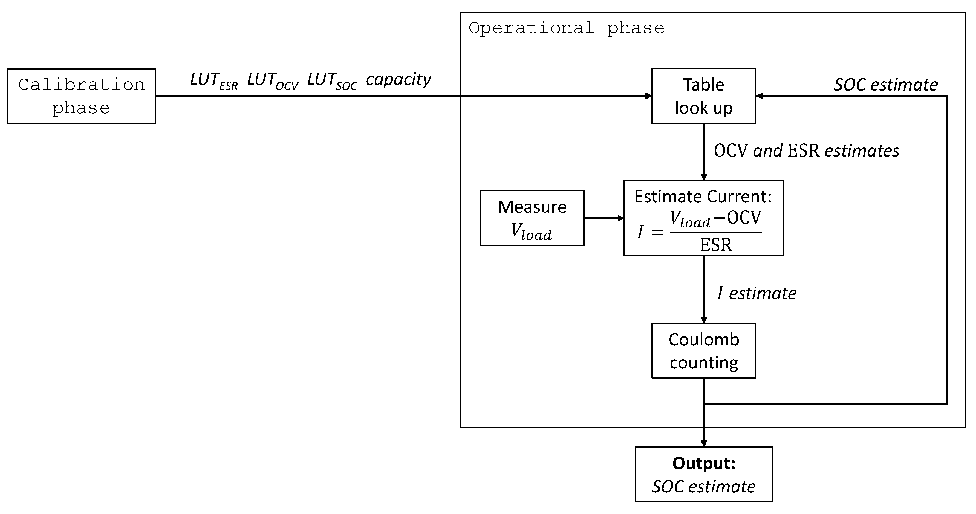
2. Proposed Shuntless SOC Measurement Method

The aim of the proposed method is to obtain an estimate of the SOC without using a shunt resistor to measure current. The only measurement that is required during operation is that of the battery voltage under load V l o a d 
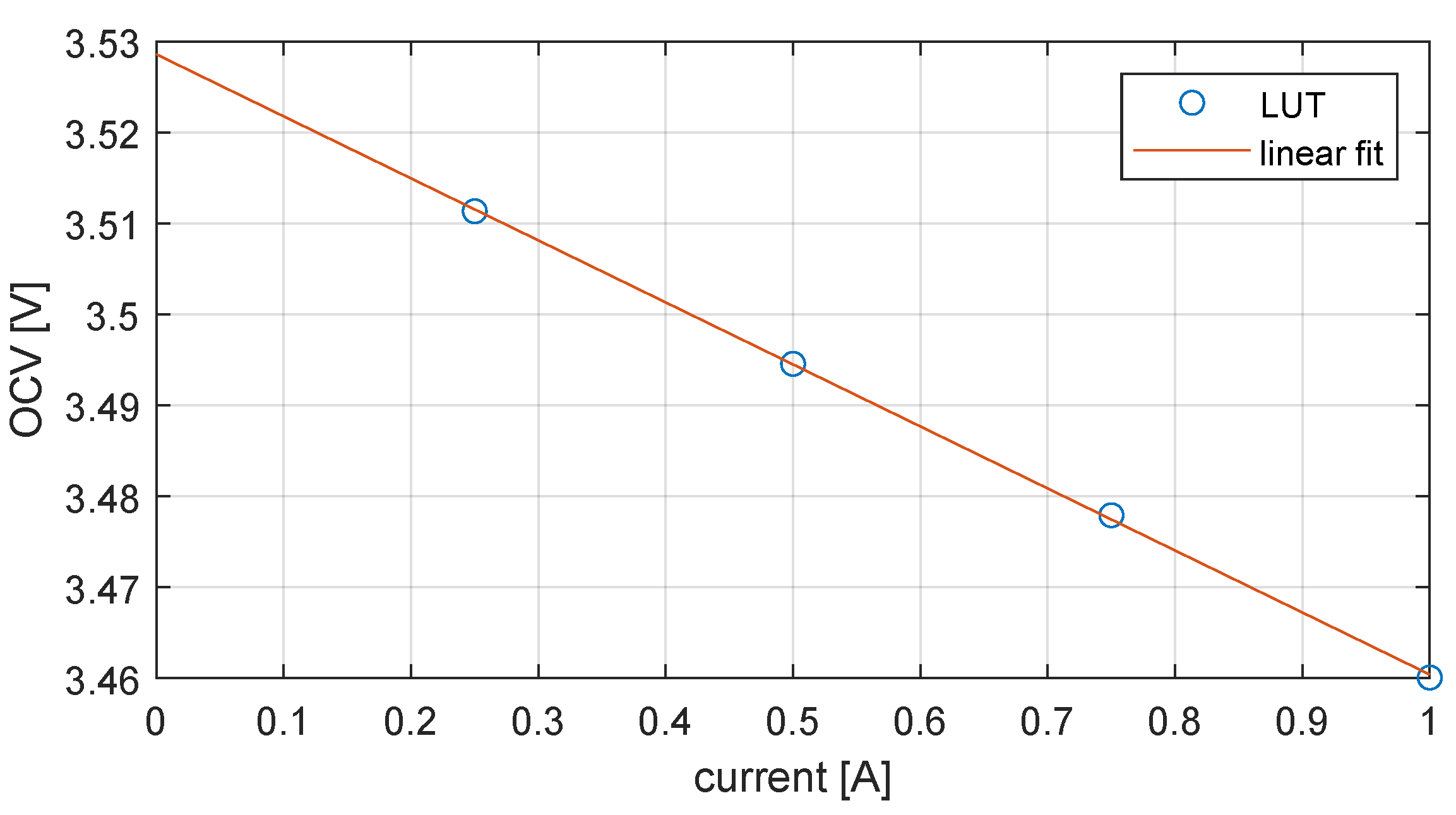
. Furthermore, look-up tables (LUTs), obtained during a preliminary calibration phase, are employed. These LUTs provide information about how the equivalent series resistance (ESR), i.e., the internal resistance of the battery, and the open-circuit voltage (OCV) vary for different values of SOC. These LUTs are built during the calibration phase by measuring the battery’s OCV, its voltage under load V l o a d , and the current for different SOC values with a reference instrument. A detailed description of the procedure to build the LUTs is given in Section 3.2.1. The ESR, coupled with the knowledge of the OCV, is used in place of the external shunt to estimate the current and perform coulomb counting in the operational phase. A block diagram illustrating the operation of the proposed method is shown in Figure 1.
The assumptions made for the proposed method are the following: (i) the capacity of the battery, the ESR-vs.-SOC, and the OCV-vs.-SOC relationships for the battery under test are known. These are measured in a preliminary offline calibration phase and encoded in LUTs; (ii) the SOC value at the initial time instant when the proposed method starts is known; (iii) measurements of the battery voltage are available during operation, while current is flowing through the battery.
The pseudo-code in Algorithm 1 describes in detail the operation of the proposed method. Specifically, this method takes as input the required LUTs that are pre-generated during a battery characterization phase. Specifically, L U T O C V contains the OCV-vs.-SOC relationship, L U T E S R contains the OCV-vs.-ESR relationship, and  L U T S O C serves as an index table. The method also requires an estimate of the battery capacity and returns as output an estimate of the SOC at every time step.
Algorithm 1 Estimate SOC.
Input: (obtained in the calibration phase) Look-up-tables L U T O C V , I 1 , , L U T O C V , I n , L U T E S R , I 1 , , L U T E S R , I n , L U T S O C , battery capacity C
Output: SOC estimate, denoted as S O C ^
 1: begin
 2:  Start condition: battery fully charged
 3:  Measure V l o a d ( 1 ) ▹ First voltage measurement
 4:   I ^ ( 1 ) V l o a d ( 1 ) L U T O C V ( 1 ) L U T E S R ( 1 ) ▹ Initial estimate of current
 5:   S O C ^ ( 1 ) 100 % ▹ Initial estimate of SOC
 6:   k 2
 7:  while True do
 8:    q ^ I ^ ( k 1 ) × ( t ( k ) t ( k 1 ) ) ▹ Charge increment (coulomb counting)
 9:    S O C ^ ( k ) S O C ^ ( k 1 ) + q ^ / C ▹ Estimate SOC at time step k
10:   return  S O C ^ ( k )
11:  Measure V l o a d ( k ) ▹ Voltage measurement at time step k
12:    j index of the entry of L U T S O C closest to S O C ^ ( k )
13:    O C V ^ linear fit of L U T O C V , I 1 ( j ) , , L U T O C V , I n ( j ) eval. at I ^ ( k 1 )
14:    E S R ^ linear fit of L U T E S R , I 1 ( j ) , , L U T E S R , I n ( j ) eval. at I ^ ( k 1 )
15:    I ^ ( k ) V l o a d ( k ) O C V ^ E S R ^ ▹ Estimate current at time step k
16:    k k + 1
17:  end while
18: end
Starting from a known initial SOC, which here is assumed to be 100%, the algorithm is first initialized by measuring V l o a d and obtaining an initial estimate of the current as I = ( V l o a d O C V ) / E S R , where OCV and ESR are given by the respective LUTs. Then, at each iteration, coulomb counting is performed using the previous estimate of I to obtain a SOC estimate, followed by an update procedure that uses the new measured value of V l o a d and table look-up operations to update the estimate of I.
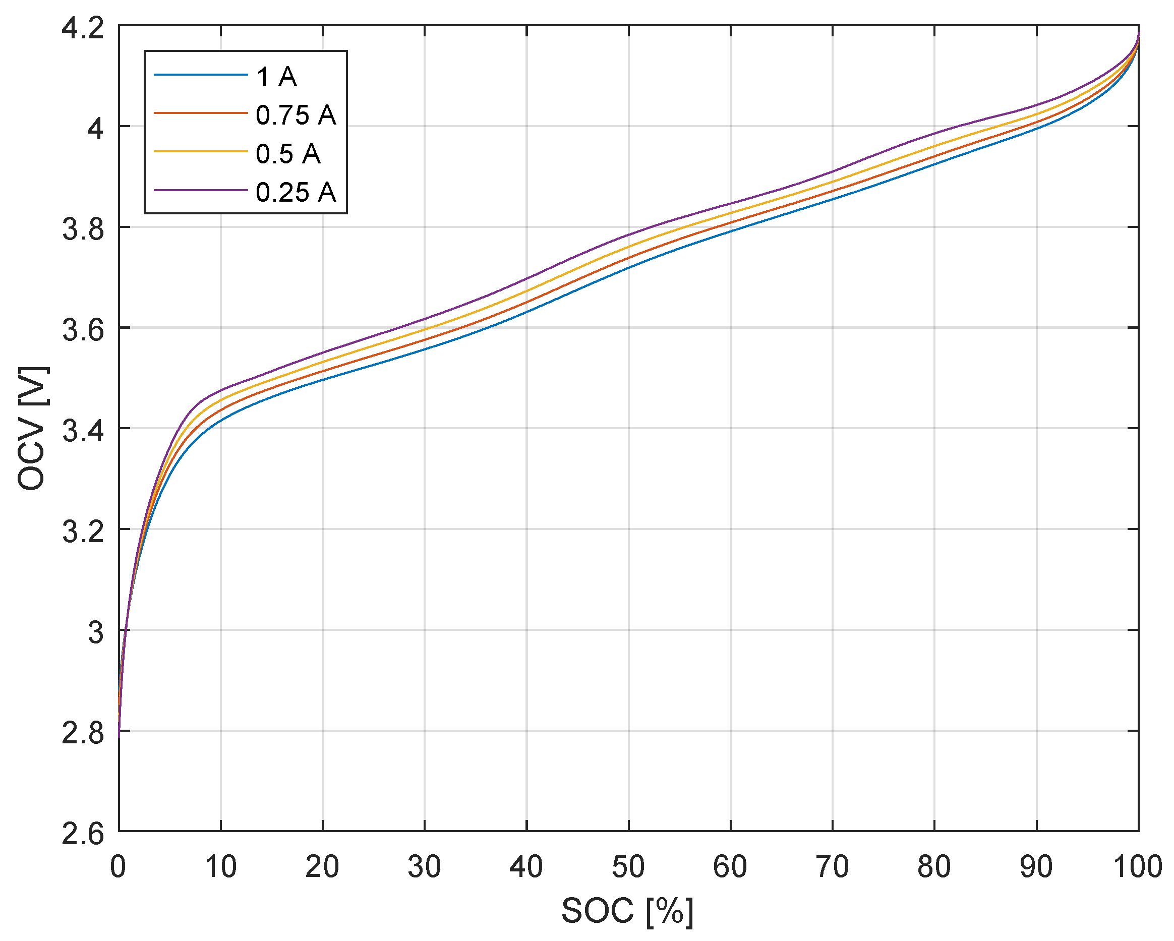
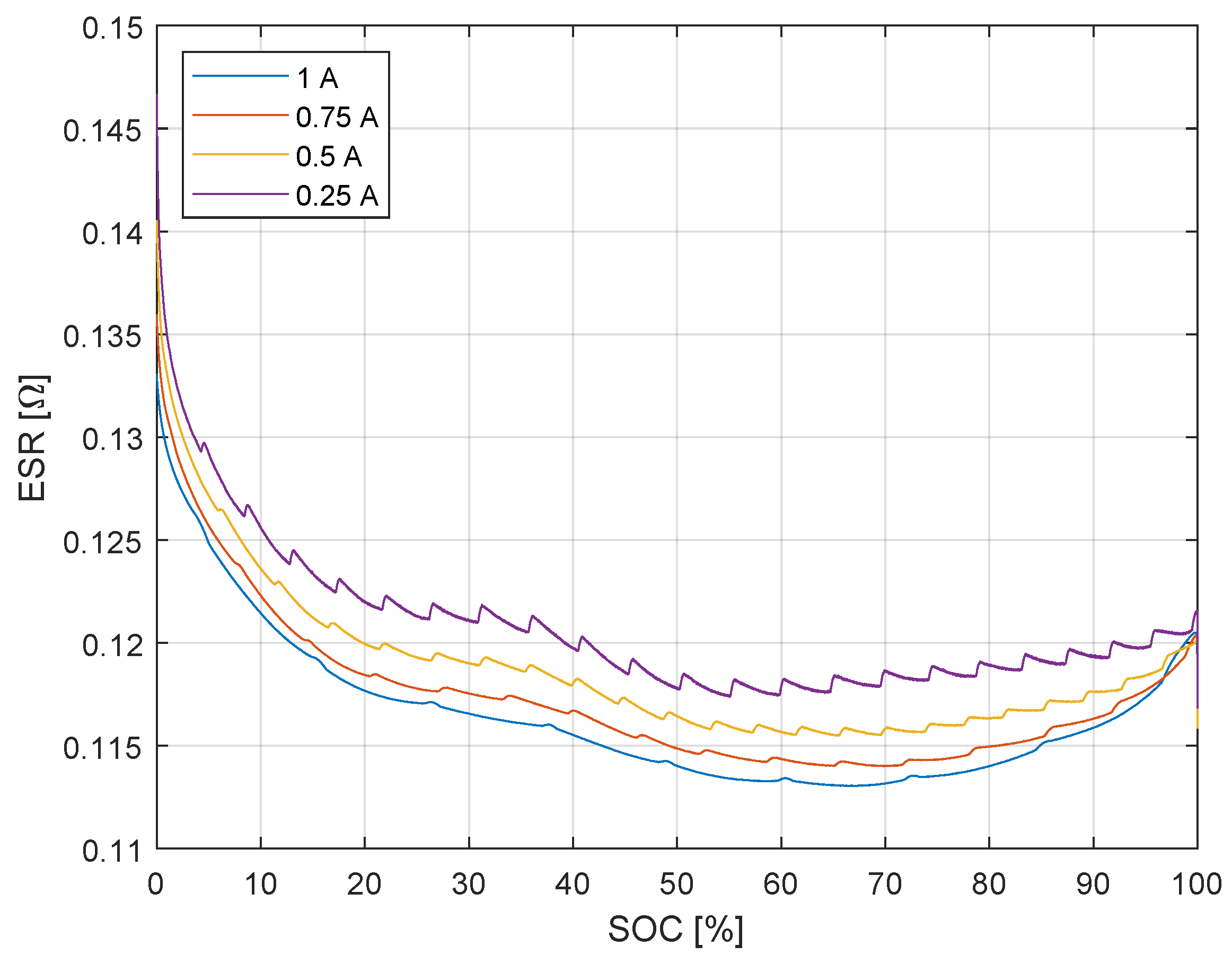
Since the OCV-vs.-SOC and ESR-vs.-SOC curves vary depending on the current flowing through the battery, in the calibration phase, the LUTs are built for n different values of the current I 1 , , I n , thus resulting in L U T O C V , I 1 , , L U T O C V , I n . Then, in the operational phase, at each time step k, the best-fit line (in a least-squares sense) on the data in L U T O C V , I 1 , , L U T O C V , I n is determined, thus obtaining a linear function f ( I ) relating current to OCV. This operation allows for using the LUTs for any generic current profile so that there is no need to use different LUTs for different current profiles. An estimate of OCV is then obtained by evaluating this function for the current estimated at the previous time step, i.e., O C V ^ = f I ^ ( k 1 ) . As described in Algorithm 1, the estimates of the ESR are obtained using the same linear regression technique as that used for the OCV.
Note that, in principle, the SOC may be estimated by simply inverting the OCV-vs.-SOC curve. However, this inversion requires that the OCV of the battery under test is measured after the relaxation period when the current is not flowing through the battery. This makes it unusable in online scenarios. Conversely, the proposed method can be employed online during battery operation.
A known initial SOC is a precondition for the proposed method. In a practical scenario, this precondition is satisfied when the battery is fully charged, i.e., after the standard charging procedure described by the manufacturer is completed. In this case, the known SOC is equal to 100%. Alternatively, when the battery is not used for a time interval longer than the relaxation period, the proposed method can still be used if the SOC is estimated using other methods, such as referring to the OCV-vs.-SOC curve or by electrochemical impedance spectroscopy.
Finally, in practical applications, the calibration procedure should be repeated periodically to account for the variations in the battery’s behavior due to aging.

3. Experimental SOC Estimation Results

To validate the proposed shuntless SOC estimation method, we performed experiments on a Mikroe SR674361P, 3.7 V LiPo pouch battery. As specified in the datasheet [18], this battery has a nominal capacity of 2000 mAh and a rated voltage of 3.7 V with a limited charge voltage of 4.2 V and a discharge cutoff voltage of 2.75 V. The specified internal resistance is less than 160 mΩ, as measured by the manufacturer at 1 kHz. In the following Section 3.1, the experimental setup is described, while the experimental procedure is detailed in Section 3.2. Then, the obtained results are presented in Section 3.3.

3.1. Experimental Setup

The experimental setup consisted of a bench-top instrument, the Keithley 2450 source measurement unit (SMU), which provides current signals and simultaneously measures current and voltage, connected via a 4-wire configuration to the battery under test. The SMU operation was timed and controlled by a custom-developed script written in the Test Script Processor (TSP) language. The measurement data acquired by the SMU were transferred to a PC, where they were processed by custom routines implemented in the MATLAB numerical computation environment.
During the experiments, the battery was placed in a small climate-controlled chamber with a temperature of 25 ± 1 °C. Prior to the experiments, the battery was preconditioned by cycling it five times at 1 A (0.5C). Note that similar preconditioning procedures are indicated by several standards for battery testing, e.g., the International Electrotechnical Commission (IEC) 62660-1 standard on “Secondary lithium-ion cells for the propulsion of electric road vehicles—Part 1: Performance testing” [19].

3.2. Experimental Procedure

Following the structure of the proposed method, described in Section 2, the measurement procedure used in the experiments was divided into two phases: the calibration phase and the operational phase, which are described in detail in the following.

3.2.1. Calibration Phase

During this preliminary phase, the LUTs were built. The LUTs consisted of the OCV-vs.-SOC and ESR-vs.-SOC curves, which were obtained by starting from a fully charged battery and discharging it with a constant current I 0 . During the discharge, V l o a d and I 0 were constantly measured by the SMU. Every two seconds, the current was also interrupted by the SMU in order to measure the open-circuit voltage (OCV) of the battery after a 10 ms transient period. Using the available measured quantities, the battery internal resistance was estimated as E S R = ( V l o a d OCV ) / I 0 , as in the widely adopted current-pulse method for battery internal resistance measurement [20].
The procedure was stopped when the voltage across the battery reached the cut-off value of 2.75 V specified by the manufacturer. The battery capacity was also measured during this stage by integrating the current. The discharging procedure was repeated four times, each time with a different value of the constant discharge current: 1 A, 750 mA, 500 mA, and 250 mA. These current values correspond to the following C-rates: 0.5C, 0.375C, 0.25C, and 0.125C.

3.2.2. Operational Phase

After the calibration phase, an experiment was performed to validate the proposed method in the operational phase. In this stage, the SMU generated a time-varying current that emulated the behavior of an electric vehicle as defined by the Worldwide Harmonized Light-Duty Vehicles Test Procedure (WLTP) [21]. In particular, this current profile is publicly available in [22], and it was obtained from the WLTP speed profile by simulating a light electric vehicle [23]. For practical reasons, in this work, the WLTP current profile in [22] was normalized so that its maximum absolute value was 1 A, which corresponds to the largest current that the SMU lab instrument can generate. The resulting WLTP current profile, which has a duration of 1800 s, is shown in Figure 2. The SMU was programmed to iteratively generate the WLTP current profile until the battery was fully discharged, which took approximately 13 h, corresponding to 25.8 iterations of the WLTP profile.
In the operational phase, the V l o a d measurement results, acquired by the SMU with a sampling period of 1 s, were fed to the proposed method in Algorithm 1, together with the LUTs from the previous calibration stage. This emulates a practical scenario where the only available measurements are those of the voltage at the battery terminals. The current measurements performed by the SMU were not used by the proposed method but were used to calculate the ground-truth reference in order to evaluate the performance of the proposed method. Therefore, the reference SOC at each time step was obtained by integrating the current measured by the SMU. The SOC estimation error e of the proposed method was calculated as the difference between the estimated SOC and the reference SOC, i.e.,
e ( k ) = S O C ^ ( k ) S O C ( k )
where k is the time step and N is the number of samples in the acquired record of the signals. The root-mean-square error (RMSE) of the SOC estimation is defined as
R M S E = 1 N k = 1 N S O C ^ ( k ) S O C ( k ) 2 .

3.3. Results

The results of the preliminary calibration phase are shown in Figure 3 and Figure 4, where the curves are measured for the following values of the current: 250 mA (0.125C), 500 mA (0.25C), 750 mA (0.375C), and 1000 mA (0.5C). Furthermore, the capacity measured during calibration with a C-rate of 0.5C is 1.94 Ah. The curves in Figure 3, showing the behavior of OCV for varying SOC, were used to build L U T O C V . Instead, the curves in Figure 4, showing the behavior of ESR for varying SOC, were used to build L U T E S R .
An example of the fitting operation performed at each time step in the operational phase is shown in Figure 5, where a linear function is fit to the OCV data measured at the same SOC for currents of 250 mA, 500 mA, 750 mA, and 1000 mA during the calibration phase and encoded in the LUTs. The good fit observed in this figure confirms that, for the purposes of the proposed method, the behavior of the OCV can be approximated to be linear with a varying current in the considered current range.
Furthermore, the results obtained in the operational phase with the realistic WLTP current profile are shown in Figure 6 and Figure 7. Figure 6 shows the estimated current as well as the reference current, i.e., that measured by the SMU. From Figure 6b, a good agreement between the estimated current and the reference current can be observed. The current error in Figure 6c is defined as the difference between the estimated current and the reference current according to the definition provided by the International Vocabulary of Metrology (VIM) [24]. Specifically, the root-mean-square difference between the estimated current and the reference current is approximately 64 mA, i.e., 6.4% of the maximum considered current. This error is relatively small, and the spike near the end of the cycle visible in Figure 6a, where the error reaches approximately 90% for a brief period of a few seconds, does not noticeably affect the RMSE computed over the entire cycle. Finally, the estimated SOC is shown in Figure 7, together with the corresponding error. The RMSE of the SOC estimation is 0.82%, and the maximum SOC estimation error is 1.45%.

4. Discussion

The results presented in 
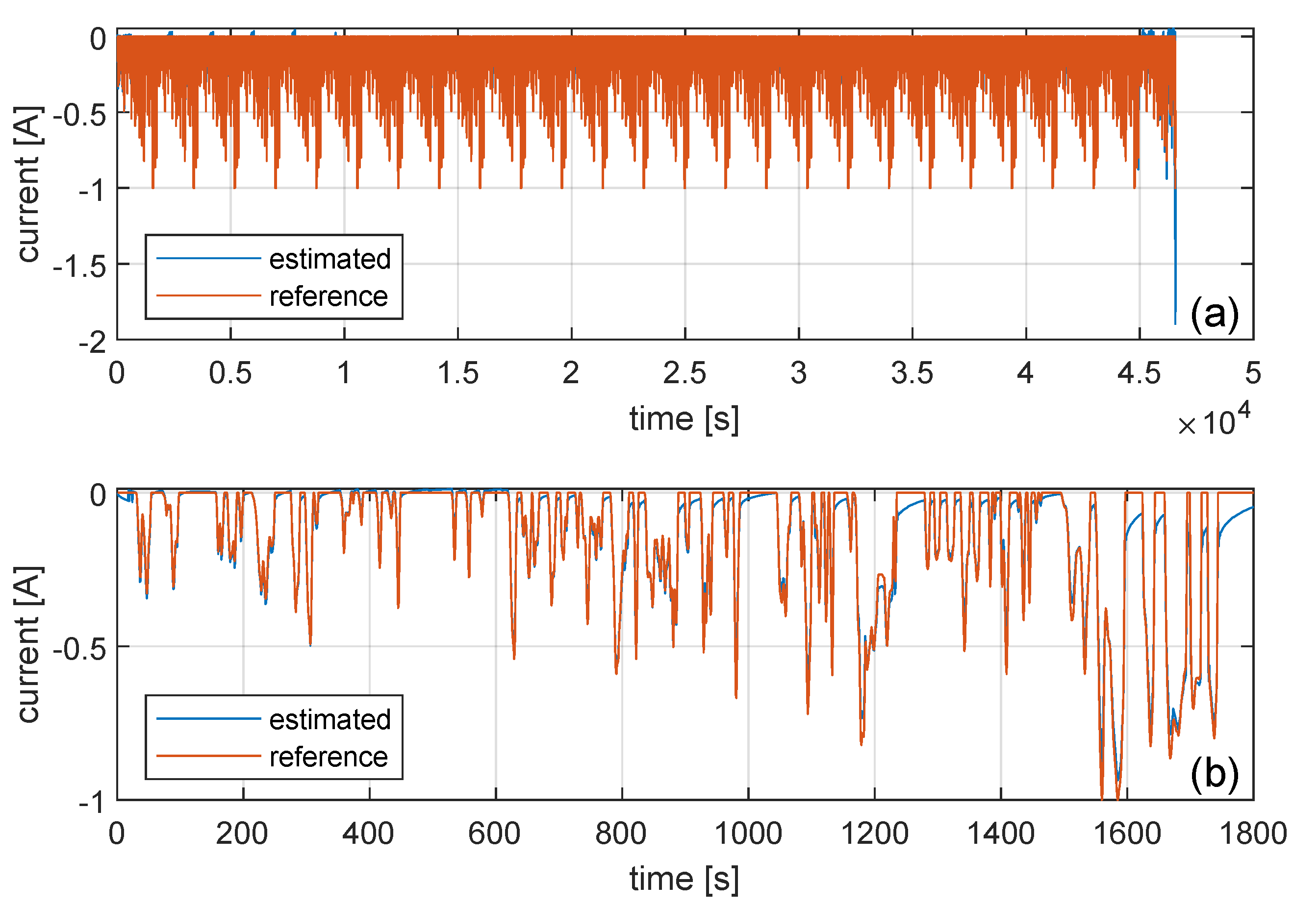
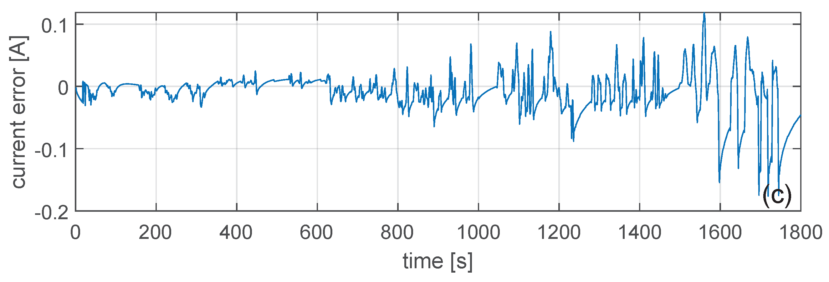
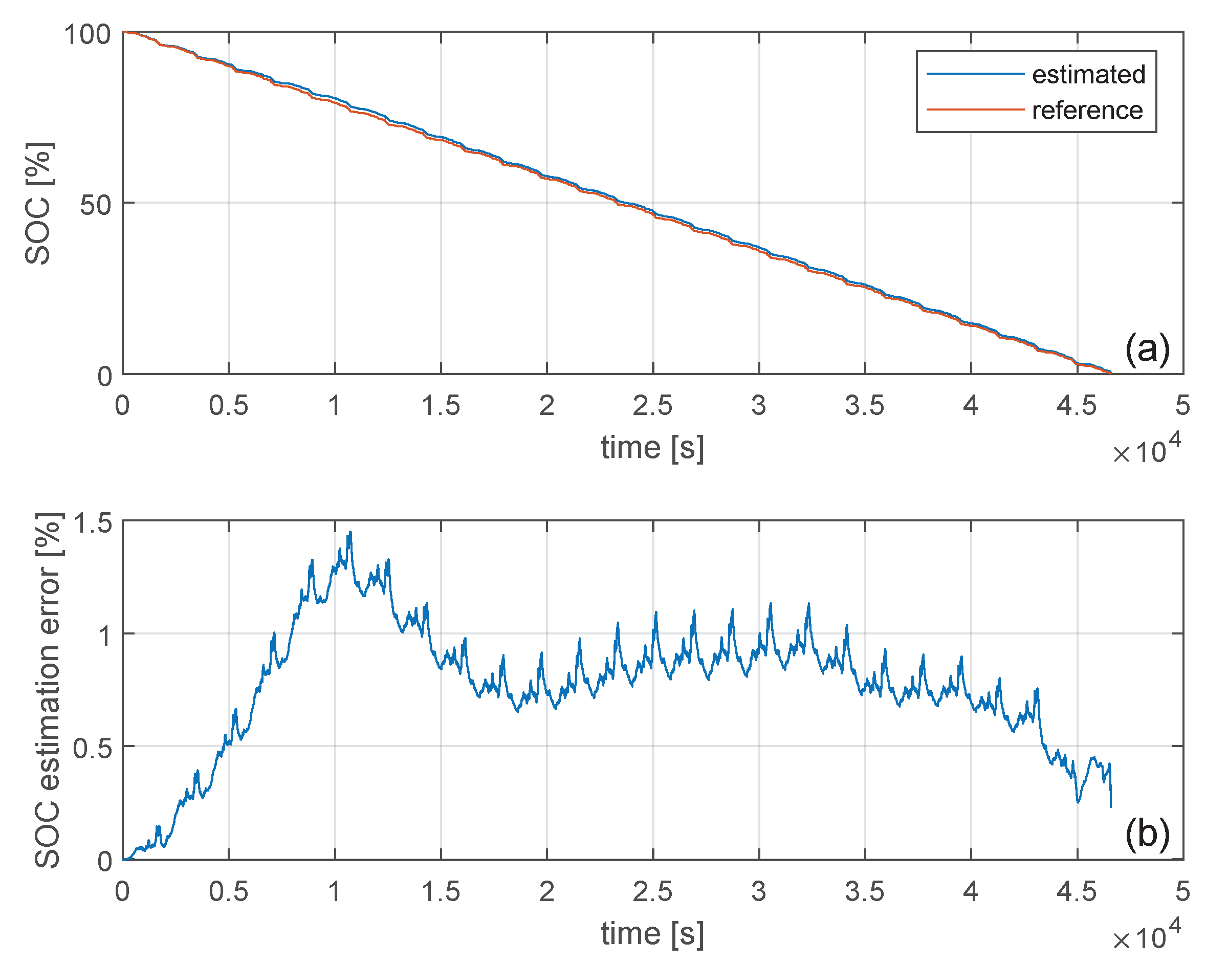
Section 3.3 prove the feasibility of the proposed shuntless SOC estimation method, with an accuracy that is sufficient for the most common battery monitoring applications (RMSE 0.82%). Such results were obtained by emulating a real-world scenario in the electrical vehicle field. Therefore, they indicate that the proposed shuntless method can be employed for in operando and in situ applications.
The SOC estimation literature contains other methods achieving errors of less than 1%, such as the proposed method, but most of these methods require the usage of an external shunt. Instead, the proposed method requires only the measurement of the voltage at the battery terminals and the usage of LUTs obtained via calibration. Therefore, it may overcome the energy consumption, reliability, and safety issues associated with the usage of an external-shunt-resistor-based current monitoring system. When comparing the results with the current-sensorless method presented in [15], the achieved SOC error is smaller. Specifically, a maximum error of 1.45% is observed in this paper, whereas a maximum error of 5% was reported in [15]. However, the proposed method follows a different approach as it does not rely on a battery equivalent circuit model and it does not use filtering techniques. Thus, it potentially has a smaller implementation complexity and wider applicability since it is not necessary to assume a specific equivalent circuit for the battery. Instead, it relies on a preliminary calibration of the battery under test. Therefore, it can be easily applied to different battery types and to various battery-powered systems.
Some factors that could potentially limit the applicability of the proposed method are the differences between specific battery samples, the influence of ageing, and the effect of the operating temperature. To compensate for the first factor, i.e., the variations in the OCV and ESR profiles between individual battery cells, the calibration procedure described in this paper should be applied individually to every battery of interest. Moreover, to mitigate the influence of battery aging, which modifies the OCV and ESR behavior with SOC, such calibrations should be repeated periodically as part of the maintenance process throughout the battery life-time, e.g., the battery should be re-calibrated after completing a certain number of operational cycles. Finally, temperature is another factor that affects the discharge profile of a battery by changing its internal resistance [25] and OCV characteristics [26]. A future development of the proposed method should therefore take into account the effect of temperature. This could potentially be done by acquiring the LUTs at several different temperatures during the calibration phase and then employing measurements from additional temperature sensors in the operational phase. Depending on the application, such sensors could already be present in the battery-powered system of interest.

5. Conclusions

In this paper, the possibility of using information about a battery’s equivalent series resistance to estimate its state of charge without directly measuring the current was investigated. In particular, a method for estimating the SOC of batteries without using a shunt for coulomb counting was presented, and its feasibility was investigated experimentally. The proposed method resulted in a SOC estimation RMSE of 0.82% in a realistic use case where a WLTP current profile was applied to a lithium polymer cell. Therefore, its feasibility was confirmed.
The described technique holds potential with the new cell-level sensors and distributed battery management systems (BMS), such as the ones proposed by the cell management unit (CMU) from Sensichips [17] since individual cell re-calibration and measurement are made possible. Potential industrial and practical applications of the proposed method are in the electric vehicle and stationary energy storage fields. In these fields, the absence of a shunt resistor would avoid the energy loss associated with large currents flowing through the shunt resistor and thus improve efficiency and safety.
Future developments include using electrochemical impedance spectroscopy (EIS) information for building OCV and ESR LUTs, which may provide benefits in terms of AC impedance characterization over a wide range of frequencies and allow the management of fast variations of the current. Additionally, applying the proposed technique to several cells connected in series, as in battery packs, may improve accuracy when estimating the SOC of the overall battery pack. Additional future perspectives include further tests using other current profiles and on different batteries, investigations on the effect of smoothing and compression of the LUTs, and the implementation of the proposed method in an embedded processor for real-time in situ applications.

Author Contributions

Conceptualization, A.D.A., P.C., F.S., M.V. and L.R.; methodology, A.D.A., P.C., F.S., M.V. and L.R.; software, A.D.A.; validation, A.D.A., P.C., F.S., M.V. and L.R.; formal analysis, A.D.A., P.C. and F.S.; investigation, A.D.A., P.C., F.S., M.V. and L.R.; resources, A.D.A., P.C., F.S., M.V. and L.R.; data curation, A.D.A., P.C. and F.S.; writing—original draft preparation, A.D.A., P.C., F.S., M.V. and L.R.; writing—review and editing, A.D.A., P.C., F.S., M.V. and L.R.; visualization, A.D.A., P.C. and F.S.; supervision, A.D.A. and P.C.; project administration, A.D.A. and P.C.; funding acquisition, A.D.A., P.C., F.S., M.V. and L.R. All authors have read and agreed to the published version of the manuscript.

Funding

This research was partially funded by the EU H2020 project SOLSTICE (GA number 963599) and by the University of Perugia “Ricerca di Base” Grant 2020.

Institutional Review Board Statement

Not applicable.

Informed Consent Statement

Not applicable.

Data Availability Statement

Not applicable.

Conflicts of Interest

The authors declare no conflict of interest. The funders had no role in the design of the study; in the collection, analyses, or interpretation of data; in the writing of the manuscript; or in the decision to publish the results.

Abbreviations

The following abbreviations are used in this manuscript:
SOCState of charge
ESREquivalent series resistance
LUTLook-up-table
OCVOpen-circuit voltage
SMUSource measurement unit
WLTPWorldwide Harmonized Light Vehicles Test Procedure

References

  1. Zhou, L.; Lai, X.; Li, B.; Yao, Y.; Yuan, M.; Weng, J.; Zheng, Y. State Estimation Models of Lithium-Ion Batteries for Battery Management System: Status, Challenges, and Future Trends. Batteries 2023, 9, 131. [Google Scholar] [CrossRef]
  2. Chang, W.Y. The state of charge estimating methods for battery: A review. Int. Sch. Res. Not. 2013, 2013, 953792. [Google Scholar] [CrossRef]
  3. Niri, M.F.; Bui, T.M.; Dinh, T.Q.; Hosseinzadeh, E.; Yu, T.F.; Marco, J. Remaining energy estimation for lithium-ion batteries via Gaussian mixture and Markov models for future load prediction. J. Energy Storage 2020, 28, 101271. [Google Scholar] [CrossRef]
  4. Niri, M.F.; Dinh, T.Q.; Yu, T.F.; Marco, J.; Bui, T.M.N. State of Power Prediction for Lithium-Ion Batteries in Electric Vehicles via Wavelet-Markov Load Analysis. IEEE Trans. Intell. Transp. Syst. 2021, 22, 5833–5848. [Google Scholar] [CrossRef]
  5. Gallien, T.; Krenn, H.; Fischer, R.; Lauterbach, S.; Schweighofer, B.; Wegleiter, H. Magnetism Versus LiFePO4 Battery’s State of Charge: A Feasibility Study for Magnetic-Based Charge Monitoring. IEEE Trans. Instrum. Meas. 2015, 64, 2959–2964. [Google Scholar] [CrossRef]
  6. Ni, Z.; Yang, Y. A Combined Data-Model Method for State of Charge Estimation of Lithium-ion Batteries. IEEE Trans. Instrum. Meas. 2021, 71, 1–11. [Google Scholar] [CrossRef]
  7. Movassagh, K.; Raihan, A.; Balasingam, B.; Pattipati, K. A Critical Look at Coulomb Counting Approach for State of Charge Estimation in Batteries. Energies 2021, 14, 4074. [Google Scholar] [CrossRef]
  8. Movassagh, K.; Raihan, S.A.; Balasingam, B. Performance Analysis of Coulomb Counting Approach for State of Charge Estimation. In Proceedings of the 2019 IEEE Electrical Power and Energy Conference (EPEC), Montreal, QC, Canada, 16–18 October 2019. [Google Scholar] [CrossRef]
  9. Baccouche, I.; Jemmali, S.; Mlayah, A.; Manai, B.; Amara, N.E.B. Implementation of an improved Coulomb-counting algorithm based on a piecewise SOC-OCV relationship for SOC estimation of li-IonBattery. arXiv 2018, arXiv:1803.10654. [Google Scholar]
  10. Liu, Z.; Li, Z.; Zhang, J.; Su, L.; Ge, H. Accurate and efficient estimation of lithium-ion battery state of charge with alternate adaptive extended Kalman filter and ampere-hour counting methods. Energies 2019, 12, 757. [Google Scholar] [CrossRef]
  11. Wang, W.; Ma, B.; Hua, X.; Zou, B.; Zhang, L.; Yu, H.; Yang, K.; Yang, S.; Liu, X. End-Cloud Collaboration Approach for State-of-Charge Estimation in Lithium Batteries Using CNN-LSTM and UKF. Batteries 2023, 9, 114. [Google Scholar] [CrossRef]
  12. Miao, J.; Tong, Z.; Tong, S.; Zhang, J.; Mao, J. State of Charge Estimation of Lithium-Ion Battery for Electric Vehicles under Extreme Operating Temperatures Based on an Adaptive Temporal Convolutional Network. Batteries 2022, 8, 145. [Google Scholar] [CrossRef]
  13. Fundaro, P. Impedance Track™ Based Fuel Gauging—White Paper; Technical Report; Texas Instruments: Austin, TX, USA, 2007. [Google Scholar]
  14. Zhu, K.; Liu, X.; Pong, P.W.T. Performance Study on Commercial Magnetic Sensors for Measuring Current of Unmanned Aerial Vehicles. IEEE Trans. Instrum. Meas. 2020, 69, 1397–1407. [Google Scholar] [CrossRef]
  15. Chun, C.Y.; Baek, J.; Seo, G.S.; Cho, B.; Kim, J.; Chang, I.K.; Lee, S. Current sensor-less state-of-charge estimation algorithm for lithium-ion batteries utilizing filtered terminal voltage. J. Power Source 2015, 273, 255–263. [Google Scholar] [CrossRef]
  16. Crescentini, M.; De Angelis, A.; Ramilli, R.; De Angelis, G.; Tartagni, M.; Moschitta, A.; Traverso, P.A.; Carbone, P. Online EIS and Diagnostics on Lithium-Ion Batteries by Means of Low-Power Integrated Sensing and Parametric Modeling. IEEE Trans. Instrum. Meas. 2021, 70, 1–11. [Google Scholar] [CrossRef]
  17. Manfredini, G.; Ria, A.; Bruschi, P.; Gerevini, L.; Vitelli, M.; Molinara, M.; Piotto, M. An ASIC-Based Miniaturized System for Online Multi-Measurand Monitoring of Lithium-Ion Batteries. Batteries 2021, 7, 45. [Google Scholar] [CrossRef]
  18. Mikroe. SR674361P Li-Polymer Battery Datasheet. 2022. Available online: https://www.mikroe.com/li-polymer-battery-37v-2000mah (accessed on 17 May 2023).
  19. 62660-1:2018; Secondary Lithium-Ion Cells for the Propulsion of Electric Road Vehicles—Part 1: Performance Testing. International Electrotechnical Commission (IEC): Geneva, Switzerland, 2018.
  20. Schweiger, H.G.; Obeidi, O.; Komesker, O.; Raschke, A.; Schiemann, M.; Zehner, C.; Gehnen, M.; Keller, M.; Birke, P. Comparison of Several Methods for Determining the Internal Resistance of Lithium Ion Cells. Sensors 2010, 10, 5604–5625. [Google Scholar] [CrossRef] [PubMed]
  21. Addendum 15: Global Technical Regulation No. 15—World-Wide Harmonized Light Vehicles Test Procedure; Technical Report; CE/TRANS/UNECE: Geneva, Switzerland, 2014.
  22. Kocsis Szürke, S.; Dineva, A.; Csomós, B. Dataset—Complex Testing Procedure for 18650 Batteries; IEEE DataPort: Piscataway, NJ, USA, 2021. [Google Scholar]
  23. Dineva, A.; Csomós, B.; Kocsis, S.; Vajda, I. Investigation of the performance of direct forecasting strategy using machine learning in State-of-Charge prediction of Li-ion batteries exposed to dynamic loads. J. Energy Storage 2021, 36, 102351. [Google Scholar] [CrossRef]
  24. JCGM 200:2012; International Vocabulary of Metrology—Basic and General Concepts and Associated Terms (VIM), 3rd ed. Joint Committee for Guides in Metrology (JCGM): Sèvres, France, 2012.
  25. Zhang, S.; Xu, K.; Jow, T. The low temperature performance of Li-ion batteries. J. Power Source 2003, 115, 137–140. [Google Scholar] [CrossRef]
  26. Gandoman, F.H.; El-Shahat, A.; Alaas, Z.M.; Ali, Z.M.; Berecibar, M.; Abdel Aleem, S.H.E. Understanding Voltage Behavior of Lithium-Ion Batteries in Electric Vehicles Applications. Batteries 2022, 8, 130. [Google Scholar] [CrossRef]
Figure 1. Operation of the proposed method, divided into two phases: calibration phase where the LUTs are built, and operational phase, where the LUTs are used together with voltage measurements to estimate the current and SOC.
Batteries 09 00286 g001
Figure 2. WLTP current profile used to validate the proposed method in the operational phase.
Batteries 09 00286 g002
Figure 3. Experimental data: OCV as a function of SOC. The curves were obtained in the calibration phase for different values of the discharging current.
Batteries 09 00286 g003
Figure 4. Experimental data: ESR as a function of SOC. The curves were obtained in the calibration phase for different values of the discharging current.
Batteries 09 00286 g004
Figure 5. An example of the best-fit line computed during the operational phase to obtain an estimate of OCV from an estimate of the current. The fit was performed on four data samples from the LUTs acquired at different currents: 250 mA, 500 mA, 750 mA, and 1000 mA.
Batteries 09 00286 g005
Figure 6. Experimental results in the operational phase. (a): Current estimated by the proposed shuntless method with a WLTP profile; (b): magnification of the curve in (a), showing a single repetition of the WLTP profile; (c): current estimation error, computed as the difference between the estimated and reference value of the current.
Batteries 09 00286 g006aBatteries 09 00286 g006b
Figure 7. Experimental results in the operational phase: (a) SOC estimated by the proposed shuntless method; (b) estimation error.
Batteries 09 00286 g007
Disclaimer/Publisher’s Note: The statements, opinions and data contained in all publications are solely those of the individual author(s) and contributor(s) and not of MDPI and/or the editor(s). MDPI and/or the editor(s) disclaim responsibility for any injury to people or property resulting from any ideas, methods, instructions or products referred to in the content.

