Article

Controlling the Molar Ratios of Cation to Anion of Precursors for High Performance Capacitive Properties of MnO2 Hybridized Carbon-Based Materials Electrode

Department of Chemical and Materials Engineering, College of Engineering, National Kaohsiung University of Science and Technology, Sanmin District, Kaohsiung City 807618, Taiwan
*
Author to whom correspondence should be addressed.
Batteries 2023, 9(5), 273; https://doi.org/10.3390/batteries9050273
Submission received: 30 March 2023 / Revised: 6 May 2023 / Accepted: 12 May 2023 / Published: 16 May 2023
(This article belongs to the Special Issue High-Performance Supercapacitors: Advancements & Challenges)

Abstract

:
Controlling the cation to anion (Mn2+/MnO4) molar ratios of the precursors was used to obtain a highly performance capacitive properties of nanostructural MnO2 hybridized carbon-based materials on nickel foam (NF) through successive ionic layer adsorption and reaction technology. SEM, XRD, BET, and XPS analyses are utilized to investigate the influence of cation/anion molar ratios of precursors on the as-obtained MnO2 electrode materials. At a lower molar ratio of cation/anion of 1, the prepared manganese oxide deposited on the NF with obvious δ-MnO2 phase. The average pore size distribution of BET analysis of the as-obtained δ-MnO2 is about 4.6 nm, the specific surface area is 155.7 m2 g−1, exhibiting a mesoporous structure. However, when the molar ratio of cation/anion is higher than 5, the deposited film produced by the reaction exhibits a γ-MnO2 crystal phase. The capacitance of δ-MnO2/NF electrode is 280 F g−1 at 1 A g−1 in a 1 M Na2SO4 aqueous electrolyte solution. In addition, reduced graphene oxide (rGO) mixed with multi-wall carbon nanotube (MWCNT) was added to synthesize γ-MnO2/rGO-MWCNT/NF electrode, which has a high capacitance of 377.4 F g−1 under the charge/discharge current density at 1 A g−1.

1. Introduction

Supercapacitors (SCs) possessing high power density demonstrate the benefits of fast charging rate and long service time, and are very important energy storage devices [1,2]. Among the SCs that have been developed, the Faraday reaction of redox is one of the most important electrode materials for charge storage. Because MnO2 possesses the advantages of cheap environmental affinity, good stability in alkaline electrolyte, and high theoretical capacitance, it is often used as the electrode of supercapacitors [3,4]. However, the general crystal phases of MnO2 are α, β, γ, δ, and λ types, each of which has a different pore structure. Among them, δ-MnO2 has a layered structure, which is suitable for intercalation and extraction of ions, and increases electrical properties. Amorphous MnO2 has a large specific capacitance; thus, in the process of charging and discharging, ion insertion and extraction will not destroy the structure of amorphous MnO2. Furthermore, γ-MnO2 has a one-dimensional tunnel structure. In addition to good capacitance performance, it also has good rate discharge performance and is suitable for high-current charging and discharging. Moreover, γ-MnO2 has excellent depolarization activity, which slows down the decay of the electrode [5]. Manganese dioxide in different crystalline states exhibits different properties such as transport, insertion, and extraction of electrolyte ions, affecting the specific capacitance value and capacitance retention performance of the electrode [6,7].
However, there are still some disadvantages in the application of high-capacity MnO2 electrodes. For example, low conductivity is one of the shortcomings of MnO2, which severely limits its application [8]. This deficiency can be made better by introducing conductivity carbon materials to the electrode materials [9,10]. Reduced graphene oxide (rGO), one of the carbon nanostructures, has exceptional capacitance, electronic, chemical stability, mechanical properties and high surface area, and has received great attention; therefore, it is also popularly applied as electrode materials for supercapacitors [11,12]. From another point of view, compounding reduced graphene oxide (rGO) with metal oxide can significantly enhance the electrical conductivity of the electrode [13]. The development of MnO2/rGO nanocomposite materials can complement each other’s shortcomings and enhance the application of the electrode materials.
Until now, many methods have been developed, such as the hydrothermal [14], liquid phase [15], solid reaction [16], and chemical precipitation methods [17,18] to prepare MnO2/rGO nanocomposites. In most methods, the product is composite powder. He et al. [19,20] published a series of reports on graphene/MnO2 hybrid electrodes. It was pointed out that nanocomposite electrodes composed of MnO2 and functionalized rGO exhibited a high specific capacitance. Mao et al. [21] utilized the precipitation method to synthesize nanostructural MnO2 compounded with tetrabutylammonium hydroxide to stabilize graphene in various mass ratios. The crystallinity, composition and morphology play crucial roles in the performance of the capacitor for the electrode material.
Successive ionic layer adsorption and reaction (SILAR) is a film coating process [22,23,24]. This method can be used to produce the required film material on the substrate, which is an easy way to achieve this. This process utilizes the substrate, repeatedly immersed it in a cation and anion solution of precursors to be deposited as a film on a substrate. The deposition time and the concentration and type of chemical reagents control the growth of the film [25,26]. Jana et al. [27] fabricated MnO2 on stainless steel substrates using hydrothermal technique or SILAR process, respectively. Moreover, graphene was coated on cloth composed of nanotube to obtain rGO/MnO2 supercapacitors. It revealed the rGO/MnO2 material prepared by hydrothermal technique consisted of serious agglomeration to decrease the specific surface area and electrical conductivity of the as-obtained electrode. In contrast, the electrode material fabricated by SILAR process possessed more surface area and demonstrate better diffusion speed of electrolyte [28]. Furthermore, the SILAR method can decrease the agglomeration of rGO and reduce the need of non-conductive binders and electrode material to decrease the fabricating cost of capacitive devices. The SILAR process is utilized to produce rGO-MnO2 composite films, which can prepare low-weight and ultra-small supercapacitors. Besides this, Jadhav et al. [29] investigated the SILAR process, finding that stainless steel was used as the base and immersed in solutions containing manganese ion to fabricate MnO2 and rGO hybrid electrode. It indicated that manganese oxide electrode film exhibited an amorphous phase, which demonstrated a facilely electrochemical redox reaction in the process of charging and discharging.
This study aims to address the necessary factors for developing a high-performance energy storage device–electrode material process for supercapacitors. Using the SILAR process, which is easy to scale industrially, we explore the crystal phase and morphology of the as-deposition MnO2 under various molar ratios of cation/anion (Mn2+/MnO4) of the precursors, and use a mixture of rGO and multi-wall carbon nanotube (MWCNT) carbon materials to hybridize with the as-deposited MnO2 for improving the conductivity of electrode, increasing the capacitance value and the charge–discharge capacitance retention rate. To the best of our knowledge, the cation/anion (Mn2+/MnO4) molar ratios of the precursors in the SILAR process effect on the electrode material characteristics, and in the electrochemical behaviors of the as-fabricated MnO2-based electrodes, is very rare.
In this study, controlling the cation to anion (Mn2+/MnO4) molar ratios of the precursors to obtain a highly performance capacitive properties for the fabrication of nanostructural MnO2 hybridized carbon-based electrode was investigated. A- 3D nickel foam was used as the substrate and the SILAR method utilized to prepare manganese dioxide-based electrode. The influences of the cation/anion molar ratio on the SILAR process for preparing MnO2/NF were investigated. Finally, the electrochemical properties of different crystal phases of MnO2-based on nickel foam electrode were characterized and investigated.

2. Materials and Methods

2.1. Synthesis of MnO2-Based Hybrid Electrode

About 0.25 g of graphene oxide (GO) sheet was taken and mixed with 50 mL deionized (DI) water. Then, stirring and mixing for 1 h, the mixed solution of pH at 10–11 was adjusted by ammonia water. After this, the GO suspension was placed in a Teflon lined autoclave and maintained at 180 °C for 12 h. Finally, after cooling, the GO suspension solution became rGO.
Before the preparation, bare NF was examined by SEM and indicated the smooth and flat surface, which can ensure the active electrode materials deposited with good uniformity (Figure S1, Supplementary Materials). The nickel foam (NF) (1 cm × 1 cm) was washed and cleaned by acetone and DI water, sequentially, then dried for the preparation of the MnO2/NF electrode by the SILAR process. The SILAR process was utilized to coat MnO2 onto the substrate. The NF was placed into various molar ratios of cation/anion, Mn2+/MnO4, to obtain MnO2 coated on NF. The cation (Mn2+) was oxidized by anion (MnO4−) and deposited layer by layer. Through the SILAR process, MnO2 was coated on the NF substrate. This electrode fabrication was repeated 5 times. Finally, the fabricated electrode was heat-treated at 200 °C for 1 h. In the experiment, different concentrations of MnSO4 (0.005 M~0.1 M) were reacted with 0.01 M KMnO4, under different molar ratios of cation/anion (Mn2+/MnO4, R represents the molar ratio of Mn2+/MnO4) to prepare the MnO2/NF electrode by the SILAR process. The fabrication of MnO2/NF electrode material is shown as Scheme 1.
The weight of rGO and MWCNT was at the ratio of 1:3 to prepare uniform suspension rGO-MWCNT mixed carbon material, which was used to deposit the electrode. The mixed carbon material contained rGO and MWCNT is represented as CM for simplification, and the MnO2/CM/NF electrode was performed under a different molar ratio of cation/anion. The detail preparation of MnO2/CM/NF hybrid electrode was described in previous research [30].

2.2. Characterization

Field emission scanning electron microscopy (FESEM) (JEOL JSM-7401F, Tokyo, Japan) was applied to characterize the microstructures of fabricated MnO2/NF electrode. X-ray diffraction (XRD) (Bruker, D8 ADVANCE, Karlsruhe, Germany) with a Cu Kα radiation at wavelength of 1.5406 Å was used to identify the crystal phases for the materials. The Brunauer-Emmett-Teller (BET) surface area data and N2 adsorption-desorption isotherms characteristics of the as-fabricated materials were characterized by a Micrometrics ASAP 2010 instrument (Micrometrics, Atlanta, GA, USA).
Furthermore, X-ray photoelectron spectroscopy (XPS) (PHI 5000 VersaProbe, Tokyo, Japan) was utilized to identify the surface composition and binding energy of the fabricated MnO2 were identified by. The binding energy of C at 284.6 eV was applied to calibrate the charge-shift of binding energy. Moreover, the XPS spectra were deconvoluted by 100% Gaussian peaks for chemical identification.

2.3. Electrochemical Properties of MnO2-Based/NF Electrodes

The electrochemical characteristics were revealed by employing a typical three-electrode electrochemical system, with a MnO2-based/NF hybrid electrode (1.0 cm × 1.0 cm) for the working electrode, an Ag/AgCl applied as reference electrode, and a Pt plate (1.0 cm × 1.0 cm) used as the against electrode, while 1.0 M Na2SO4 aqueous solution was applied as the electrolyte.
Cyclic voltammetry (CV) and galvanostatic charge/discharge (GCD) tests were applied to characterize the electrochemical properties by a CHI 760D electrochemical workstation.
The specific capacitance (Cm) was calculated on the basis of discharging curved line of the GCD examination by Equation (1):
C m = i × Δ t Δ V × m      
where i (A) represents the current of discharge, Δt (s) means the time of discharge, ΔV (V) expresses the change of discharging potential, and m (g) indicates MnO2 active material’s mass.

3. Results and Discussion

3.1. Physical Properties of the as-Prepared MnO2 Materials

Figure 1a reveals the morphology of the deposited MnO2, showing a flower-like cluster structure; the typical size of the clusters is 60–120 nm, and there is a large distance between the clusters. Furthermore, the structure of the clusters contains about 5 nm–15 nm elongated elliptical MnO2 particles. Figure 1b also shows the cluster structure (the typical cluster size is 50–80 nm), and the MnO2 particles are composed of near spherical and elliptical particles; the typical particle size is 8–15 nm. The prepared MnO2 material also has many pores between the clusters, but compared with Figure 1a, it is obvious that the MnO2 particles are denser and the distances between the clusters are smaller. In contrast, Figure 1c presents a morphology different from that of Figure 1a,b. The deposited MnO2 particles in Figure 1c are very compact and uniform; the shape is granular with a typical size of 10–15 nm; while in Figure 1d, the shape of the clusters is hardly observed, but the as-deposited MnO2 exhibits a uniform granular distribution. There are many pores between the particles in Figure 1d, and the typical particle size is 12–18 nm.
SEM images show that the deposited MnO2 exhibits different morphologies, presumably affected by the molar ratio of cation/anion in the SILAR process. It is initially found that the material shown in Figure 1a,b is MnO2 obtained from a lower molar ratio of cation/anion (R = cation/anion = 1/2, 1), while the morphology of MnO2 is similar; Figure 1c,d show MnO2 obtained from relatively higher molar ratio of cation/anion (R = cation/anion = 5, 10), while the morphology of MnO2 is similar. This may be related to the phase form of MnO2 (the XRD analysis will be described in detail later).
The XRD of bare NF was examined. The diffraction peaks of NF are approximated at 44.3°, 51.8° and 77.6° (Figure S2, Supplementary Materials). The peak at 44.3° with the strongest intensity corresponds to the (111) crystal plane of NF, so as to avoid overlapping with the (300) plane of γ-MnO2 at 42.7°. In this study, the as-synthesized MnO2 powders were used for XRD analysis. The XRD analysis of MnO2 prepared under different molar ratios of cation/anion is shown in Figure 2a. When the molar ratio of cation/anion was 1/2 to 1, XRD diffraction patterns were identified as δ-MnO2, and were consistent with JCPDS card number 18-0802 [31]. When the molar ratio of cation/anion is 5 to 10, XRD analysis shows that the deposited MnO2 is γ-MnO2 [32], corresponding to JCPDS card number 14-0644.
Nevertheless, the main diffraction peak at 2θ of 37.2° is visible, owing to the (111) crystal plane of δ-MnO2 (JCPDS 18-0802). Similarly, the main diffraction peak at 2θ of 37.1° contributes to the (131) plane of γ-MnO2. The deposited film prepared by various molar ratios of cation/anion by the SILAR process; no matter whether it is δ-MnO2 or γ-MnO2, its crystalline strength is not high. Bragg’s Law (nλ = 2d sinθ) is applied to estimate the interplanar spacing of the (111) plane in δ-MnO2 and the (131) plane in γ-MnO2; they are computed to 0.243 nm and 0.242 nm, respectively.
Figure 2b shows the analysis of the adsorption/desorption isotherms of MnO2 obtained under different reactant concentrations. The results indicate that all the obtained MnO2 show type IV adsorption/desorption isotherms, and the adsorption isotherm show a sharp rise at the position of higher relative pressure (P/Po). The adsorption/desorption curve of MnO2 prepared at molar ratio of cation/anion of 1/2 and 1, respectively, when the relative pressure (P/Po) is between approximately 0.4–0.8, there is a long and narrow desorption hysteresis loop, which is a slit-shaped pore. The adsorption/desorption curve reveals that the MnO2 prepared at molar ratio of cation/anion of 1/2 to 1 possesses a higher fraction of a lower size porous structure. Since the reactants and by-products can diffuse faster in the MnO2 with the mesoporous structure, it enhances the oxidation efficiency of electrode [33,34].
As the relative concentration of KMnO4 increases, the relative pressure (P/Po) exhibits at 0.8–1.0 of γ-MnO2, and a desorption hysteresis loop appears in the adsorption/desorption curve. The large hysteresis loop at higher P/Po in the curve of MnO2 prepared at a molar ratio of cation/anion of 5 to 10, and the curve area of the hysteresis loop decreases step by step, indicating that the pore diameter increases. This is because of the crystalline morphology transform from δ-MnO2 to γ-MnO2 [35]. BET analysis results show that the specific surface area of MnO2 obtained from molar ratio of cation/anion at 1/2, 1, 5, and 10 is 202.4 m2 g−1, 155.7 m2 g−1, 40.8 m2 g−1 and 40.5 m2 g−1, respectively; the average pore size distribution is about 6.2 nm, 4.6 nm, 29.6 nm and 28.6 nm, respectively, as shown in Figure 2c. Obviously, the increase in the molar ratio of cation/anion (Mn2+/MnO4) causes a reduction in the specific surface area of MnO2 and increases the average pore size.
To study the chemical composition of δ-MnO2 material, XPS analysis was performed as shown in Figure 3. Figure 3a shows the full range survey from 0–1200 eV of XPS analysis of the as-deposited MnO2 material. The results confirmed that only Mn, Ni, O, and C atoms exist on the surface of the product. Figure 3b shows the binding energy of Mn 2p by XPS analysis. It indicates that the two main peaks are centered at 642.2 eV and 654.0 eV, corresponding to the binding energy of Mn 2p3/2 and Mn 2p1/2 [36], compared with the difference of spin energy between Mn 2p3/2 and Mn 2p1/2, which is 11.8 eV, which is in good agreement with the reports of literature [37].
It is difficult to observe the oxidation state of Mn from the Mn 2p of XPS spectrum, and the valence states of Mn differs in the split spin energy gap. Therefore, the Mn 3s peak is split into two parts, and the binding energy difference of the two parts can be applied to clarify the oxidation state form of Mn. Figure 3c indicates that the binding energy of Mn 3s is 84.3 eV and 89.0 eV. The binding energy difference is 4.7 eV, which reveals that the manganese composition in the as-fabricated MnO2 is Mn4+ [38].
Figure 3d indicates the binding energy of O 1s in MnO2 material. After curve deconvolutional analysis, the peaks are at 529.9 eV and 531.6 eV, which corresponds to the binding energy peaks of Mn-O and Mn-OH bonding, individually. The observations are consistent with the results in the literatures [39,40].

3.2. Morphologies of the as-Deposited MnO2/CM/NF Hybrid Electrode

Figure 4a–d is the TEM images of the fabricated MnO2/CM/NF (the upper right corner of the figure is electron diffraction ring), respectively. From TEM analysis, it was clearly found that the material contained granular, thin laminar and hollow tubular structures, which are MnO2, rGO and MWCNT, respectively. Comparing the materials prepared under different molar ratios of cation/anion (Mn2+/MnO4), it is obvious that the mixed carbon material of rGO-MWCNT can effectively disperse the deposited MnO2 at low molar ratio of cation/anion (R = 1/2, 1, forming δ-MnO2). The deposition of MnO2 decreases the aggregation; as the molar ratio of cation/anion increases (R = 5, 10), the deposited MnO2 is denser, but rGO-CNT also has the effect of reducing the aggregation of the deposited particles. In addition, from the electron diffraction of TEM, there appear some ambiguous diffraction rings. It can be concluded that the prepared δ-MnO2 and γ-MnO2 have low crystallinity. This is consistent with the previous XRD analysis. During the SILAR preparation, graphene will rearrange, creating exorbitant surface aggregation; thus, it is not easy to obtain a better-ruled arrangement of MnO2 in the MnO2/CM/NF electrode.
HRTEM image of the MnO2/CM/NF from Figure 4c is indicated in Figure 4e,f. The lattice patterns of MnO2, rGO, and MWCNT were found. It exhibits the interplanar spacing of γ-MnO2, rGO and MWCNT to approximately 0.42 nm, 0.40 nm and 0.35 nm. The lattice spacing value is very close to the XRD analysis results reported in the above section. Furthermore, the MWCNTs adhere with MnO2 nanoparticle, which exhibits the structural stability for MnO2/CM/NF nanocomposite electrode. It means the microstructure can reduce the ion and electron transport length between electrolyte and MnO2/CM/NF electrode and also improve their contact surface area. In addition, the corresponding inverse fast Fourier transformation (IFFT) analysis of the lattice spacing on the HRTEM images was also performed. Again, their lattice spacings are consistent with the HRTEM analysis as shown in Figure 4g–i. During the IFFT analysis, the relevant information of FFT were also examined as shown in Figure S3 (Supplementary Materials). The fabricated MnO2/CM/NF can be expected to demonstrate extraordinary electrochemical characteristics. Furthermore, Mn, C and O elements dispersed well in the hybrid electrode (Figure 4j–l), revealing that MnO2 has fine dispersibility between the rGO and MWCNT mixed carbon material.

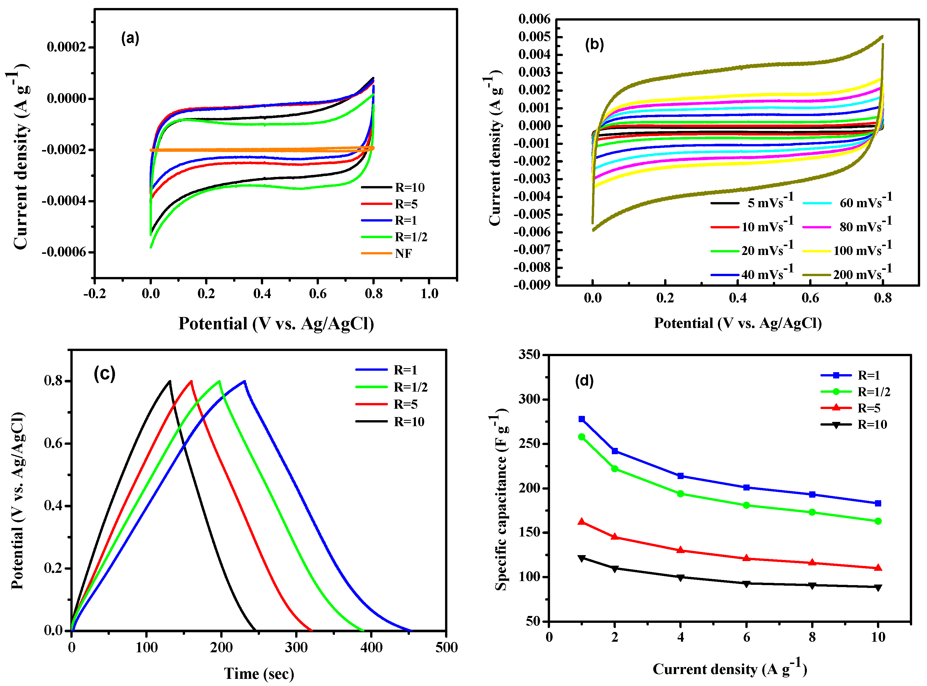
3.3. Electrochemical Properties Analysis of MnO2/NF Electrode

The MnO2/NF electrode prepared under different molar ratios of cation/anion over five cycles of the SILAR process was characterized by CV and GCD examination, respectively.
The CV characteristic of bare NF shows that at very low scan rates, the curve is very unstable. In contrast, at 50 mV s−1, it exhibits relatively stable CV characteristic (Figure S4, Supplementary Materials). Therefore, in this study, the CV characteristic of the electrode is generally performed at 50 mV s−1. Electrochemical properties of the fabricated MnO2/NF electrodes at various molar ratios of cation/anion are shown in Figure 5. As seen from Figure 5a, the bare NF with much lower area in CV curve; thus, it can be used as the base for the deposition of electrode material. The CV curves show that the MnO2/NF electrode was prepared from molar ratio of cation/anion at 1, the CV curve is quasi-rectangular and the curve area is the largest, indicating an excellent capacitance characteristic. Moreover, δ-MnO2/NF electrode prepared from R = 1, the CV curve at 20–100 m V s−1 presents a quasi-rectangular shape, exhibiting that the electrode is stable in this range (Figure 5b). Figure 5c,d show the GCD characteristics at 1 A g−1 for MnO2/NF electrode fabricated from various molar ratios of cation/anion, exhibiting that the MnO2/NF electrodes prepared from the cation/anion molar ratio at 1/2, 1, 5 and 10 have specific capacitances of 258 F g−1, 280 F g−1, 202 F g−1 and 146 F g−1, respectively. Combined with the previous XRD analysis, when the molar ratios of cation/anion increase from 1 to 5, the phase of the as-prepared MnO2 changed from δ-MnO2 to γ-MnO2 by the SILAR process. The previous BET analysis shown that δ-MnO2 revealed the largest specific surface area and demonstrated the largest specific capacitance, which can be conformed with each other. All samples showed symmetrical and nearly linear shape in the process of charge/discharge, and had longer discharge time, indicating that they have good pseudo-capacitance characteristics [41].
δ-MnO2 electrode obtained from R = 1 was subjected to various current densities for GCD performance examination at 1, 2, 4, 6, 8, and 10 A g−1; at such conditions, the capacitance values is 280, 242, 214, 201, 193 and 183 F g−1, respectively. The GCD curve almost shows the symmetry of charging and discharging. Moreover, with the increase of electrical current density, it causes to shorter charge and discharge time as shown in Figure 5d, because the rapid voltage rises at higher current density.
Comparing with the CV curve, GCD test and XRD analysis, it is proved that low-crystalline δ-MnO2 is produced at a molar ratio of cation/anion at 1, compared to the γ-MnO2 produced by molar ratio of cation/anion > 5, showed better electrochemical characteristics. However, as seen from Figure 5d it shows that the δ-MnO2/NF electrode has a high capacitance, but the capacitance stability under different current densities is less stable than that of γ-MnO2/NF electrode. Therefore, γ-MnO2 is most popularly applied in the electrodes of devices for energy storage, because the electrical activity decrease of γ-MnO2 is slower than other crystal phases of MnO2 during the electrochemical process [42].

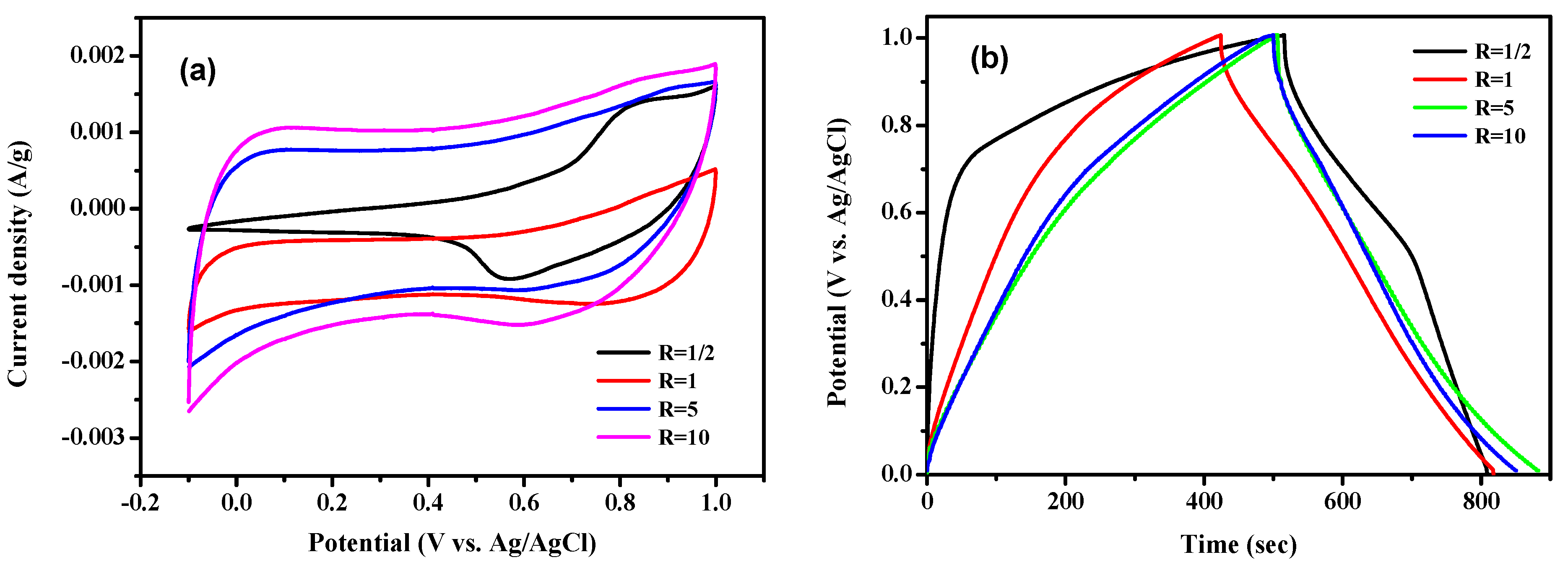
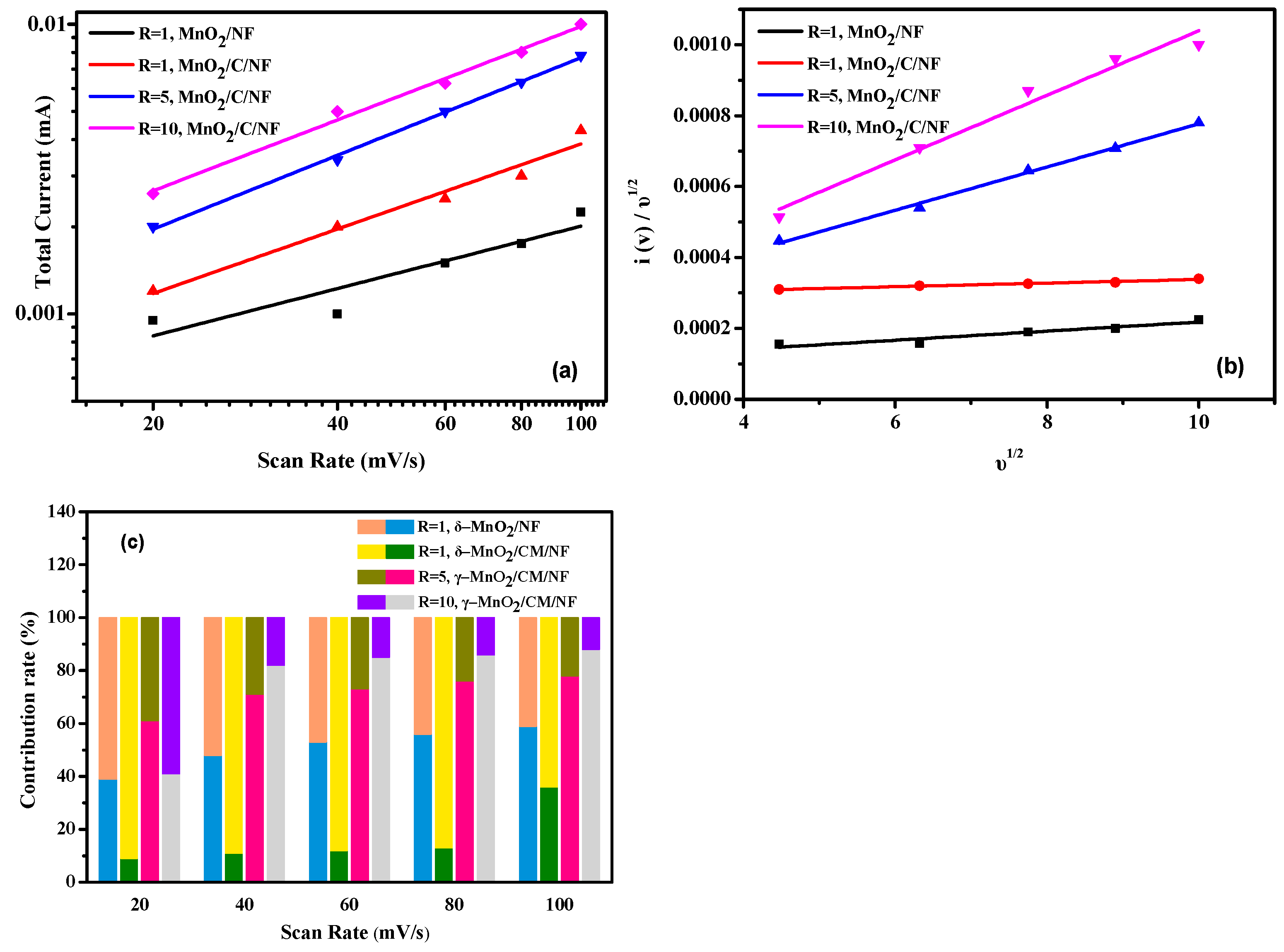
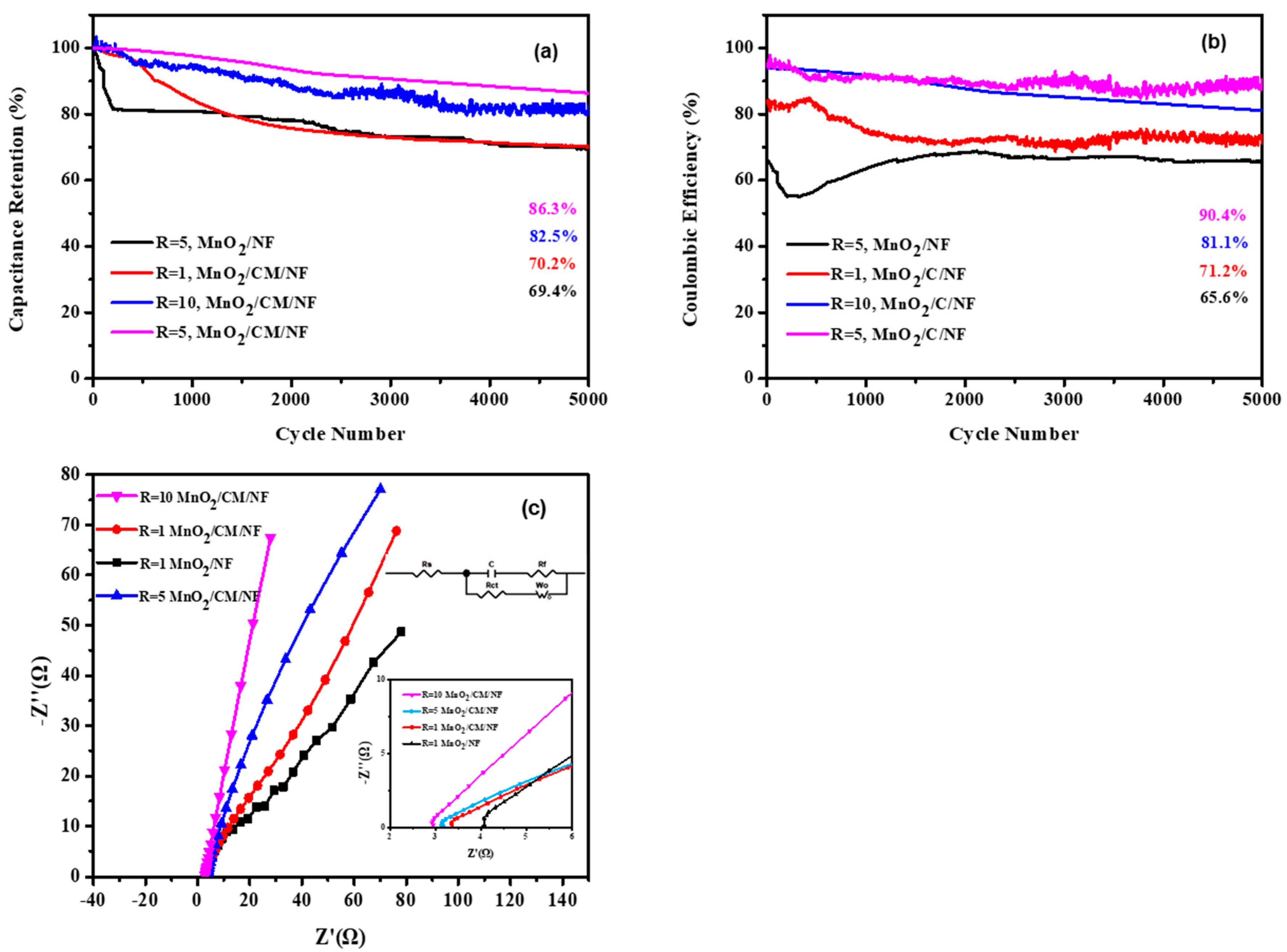
3.4. Electrical Analysis of MnO2/CM/NF Hybrid Electrode

The CV and GCD analyses were utilized to examine and reveal the electrochemical properties of the fabricated MnO2/CM/NF electrode as shown in Figure 6. Figure 6a shows the CV characteristic curves of different MnO2/CM/NF electrodes at 20 mV s−1. For the δ-MnO2/CM/NF electrode prepared at R = 1/2, the redox peak exhibits in the CV characteristic curve, and appears the smallest area of the CV curve. It means that the capacitance of this electrode is the lowest. For the δ-MnO2/CM/NF electrode prepared at R = 1, the CV characteristic curve presents a slightly quasi-rectangular shape, indicating that this electrode has a higher capacitive property than that of the electrode obtained at R = 1/2. This may be because the δ-MnO2/CM/NF electrode prepared by R = 1 is more densely deposited on CM than the electrode obtained by R = 1/2. In addition, the γ-MnO2/CM/NF electrode obtained when R is 5 and 10, respectively, and has ideal quasi-rectangular shape and a large CV curve area. It shows that the formation of γ-MnO2/CM/NF electrode has better capacitive properties.
Figure 6b shows the GCD characteristic of different MnO2/CM/NF electrodes at 1 A g−1. At the beginning of the discharging, the potential shows a sudden drop, which is caused by the inner electrical resistance of the electrode [43]. The smaller the potential drop of the electrode, the smaller the internal resistance. Comparing the different MnO2/CM/NF electrode prepared by various molar ratios of cation/anion. The GCD curve shows that for the δ-MnO2/CM/NF electrodes prepared by R = 1/2 and 1, the steep drop of the discharge curve is much lower than that prepared by R = 5 and 10. It is indicated that the electrode internal resistance of δ-MnO2/CM/NF is small, because the electrode possesses a layer structure for intercalation and extraction of ions, resulting in a smaller potential drop than that of γ-MnO2/CM/NF.
The second section of the discharge curve is a linear property of the potential dependence on time, representing the EDLC characteristic. The GCD test shows that these four curves all have the above-mentioned curve segments, and the curve of γ-MnO2/CM/NF (R = 5 or 10) has a higher slope and better linearity, which means γ-MnO2/CM/NF electrode material has strong EDLC characteristics; therefore, the electrode can present a relatively stable discharge performance.
The slope variation depended on the time is corresponding to the reaction of charge transfer of MnO2/NF electrode, which is pseudo-capacitance property. It is caused by the adsorption/desorption or oxidation/reduction occurring on the interface between electrolyte and electrode during the electrochemical reaction [44]. It indicates γ-MnO2/C/NF electrode prepared by R = 5 has obvious tailing phenomenon between 0–0.2 V, which means that it has more significant pseudo-capacitance behavior. Under R = 5 and 10, that is, at a higher concentration MnSO4 during the SILAR process, the dense γ-MnO2 can be produced on the mixed carbon material; therefore, the capacitance value of γ-MnO2/CM/NF electrode can be increased. In addition, a δ-MnO2/CM/NF electrode made by R = 1/2 shows a steep discharge curve in the low voltage region, demonstrating a strong Faraday effect [45]. The capacitance from a GCD test of the MnO2/CM/NF obtained from R = 1/2, 1, 5, and 10 is 291.3, 391.7, 377.4, and 351.7 F g−1, respectively
Figure 7 is the CV characteristic curve of MnO2/CM/NF electrode at different scan rates. From Figure 7a, the CV curve of the MnO2/CM/NF obtained under R = 1/2 has a redox peak, which is obviously different from other electrodes. Compared with the TEM analysis of the electrode, the as-deposited δ-MnO2 at R = 1/2 is prepared at a lower concentration of MnSO4, δ-MnO2 deposited is looser, and the CV curves of the electrode at different scan rates appear redox peak. In addition, the CV curves of the other three electrodes (Figure 7b–d), at low (5 mV s−1 and 10 mV s−1) and very high (200 mV s−1) scan speeds, exhibit deviations from quasi-rectangular shape, meaning that the CV characteristics of the electrode are unstable at very low and extremely high scan rates. Symmetrical CV curves are present during 20 mV s−1 to 100 mV s−1, which is a quasi-rectangular shape. Comparing Figure 7b–d, it is obvious that the δ-MnO2/CM/NF electrode prepared by R = 1, the CV curve is more easily influenced by the change of scan rate, and, relatively, for the γ-MnO2/CM/NF electrode prepared by R = 5 and 10, the CV curve is relatively stable under the change of scan rate, showing a more symmetrical quasi-rectangular shape curve.
The overall electrical current (i(v)) for CV characterization at various scan speeds of the electrode are composed with two parts as follows. One is the capacitance (icap) contribution and the other one is diffusion control (idiff) contribution. Both can be computed by Equation (2) [46].
i ( V ) = i c a p + i d i f f = a × v b
where ν represents the scan rate of CV measurement, i(V) delegates the overall electrical current for CV measurement, and “a” value and “b” value are parameters of Equation (2). The “b” value is the slope of a chart drawn by log(i(V)) vs. log(ν).
Figure 8a indicates the b-value of MnO2-based/NF electrodes. It reveals that the two γ-MnO2/CM/NF electrodes have b-value at “0.8 < b < 1”and correspond to pseudocapacitive material having a majority of capacitive storage behavior, while the other two δ-MnO2/NF electrodes exhibiting “0.5 < b < 0.8” are demonstrating a majority of Faraday mechanism. However, b = 1 is identified to be EDLC behavior, and b = 0.5 is judged to be a battery-type property [47].
Furthermore, to examine the diffusion controlled faradaic behavior (idiff) and capacitive current contribution process (icap) at a set potential with various scan speeds, Equations (3) and (4) were applied [48].
i ( V ) = a 1 v + a 2 v 1 2
i ( V ) / v 1 / 2 = a 1 v 1 / 2 + a 2
where, a1ν and a2ν1/2 attributes to icap and idiff, respectively. At a set potential of 0.5 V, a1 and a2 were calculated from Equation (4) as shown in Figure 8b. From Figure 8b, δ-MnO2/NF prepared by R = 1, a1 is 1.3 × 10⁻⁵, a2 is 9.0 × 10⁻⁵; the δ-MnO2/CM/NF prepared by R = 1, a1 is 5.1 × 10⁻⁶, a2 is 2.9 × 10⁻⁴; γ-MnO2/CM/NF prepared by R = 5, a1 is 6.1 × 10⁻⁵, a2 is 1.7 × 10⁻⁴; γ-MnO2/CM/NF prepared by R = 10, a1 is 9.1 × 10⁻⁵, a2 is 1.3 × 10⁻⁴. As seen from Figure 8c, it indicates that icap/idiff (current contribution rates) of each electrode increases with the increase of scan speed; it means that the scan speed in the stable CV state is beneficial to the improvement in capacitive process.
Comparing the relationship between scan rate and icap/idiff of δ-MnO2/NF electrode and δ-MnO2/CM/NF electrode, δ-MnO2/CM/NF electrode is due to the hybrid of rGO and MWCNT with δ-MnO2, possesses a lower icap/idiff value; that is, the icap of the δ-MnO2/CM/NF electrode is relatively small. This may be due to the insufficient concentration of δ-MnO2 deposited on the mixed carbon materials, resulting in icap cannot be increased, and the current is mainly contributed by the faradaic diffusion-controlled process.
In the γ-MnO2/CM/NF electrode (prepared by R = 5 and 10), icap/idiff value of the electrode is much higher than the value of δ-MnO2/NF. The γ-MnO2/CM/NF electrode presents a high proportion of icap, showing capacitive capacitance properties. This may be based on the electrode material prepared by SILAR process, sufficient MnSO4 concentration makes γ-MnO2 deposited on the mixed carbon materials much denser. Furthermore, rGO can make the conductivity of electrode much better, and MWCNT can effectively reduce the aggregation of γ-MnO2 deposited on carbon materials, which can improve the uniformity, and exhibit excellent capacitive values of the as-deposited material.
As to the electrode performances and impedance analysis of the as-fabricated MnO2-based/NF electrode, the capacitance retention rate of γ-MnO2/CM/NF electrode obtained from R = 5 and 10, respectively, is 86.3% and 82.5%, respectively, for 5000 cycles of charge/discharge at 1 A g−1; however, the retention is higher than that of the δ-MnO2/CM/NF electrode (70.2%). In particular, for the δ-MnO2/NF electrode (without hybridization of mixed carbon material), the specific capacitance has a serious attenuation after about 200 cycles of charge-discharge test (Figure 9a). This may be due to being without hybridization of the mixed carbon material of the electrode, resulting in partial shedding of the active material.
The Coulombic efficiency of electrode is popularly utilized to reveal the reversibility of the adsorbed and desorbed electrons on it; thus, it can be applied to understand the capacitance stability and electron transfer of electrode [49]. As seen from Figure 9b, the results show that the γ-MnO2/CM/NF hybrid electrode has excellent charge-discharge reversibility. Especially for the γ-MnO2/CM/NF hybrid electrode fabricated at R = 10, the charge–discharge process is very stable, while at R = 5 the Coulombic efficiency of the obtained γ-MnO2/CM/NF hybrid electrode is as high as 90.4%. Combining the capacitance retention and Coulombic efficiency, the high capacitance retention and excellent stability of the γ-MnO2 electrode can be revealed. This is also consistent with the existing literature [5,50].
Electrochemical impedance spectroscopy (EIS) was also examined for the as-fabricated MnO2-based/NF electrodes (δ-MnO2/NF (R = 1), δ-MnO2/CM/NF (R = 1), γ-MnO2/CM/NF (R = 5), γ-MnO2/CM/NF (R = 10)). The exhibiting Nyquist diagram is shown in Figure 9c.
At a high frequency region, interception of at the real axis (Z’) reveals the equivalent series resistance (ESR). This contains ionic electrical resistance of electrolyte, intrinsic resistance of the electrode, and contact electrical resistance between the active material and current collector interface [51]. During frequencies of 100 KHz to 10 MHz, the electrode γ-MnO2/CM/NF (R = 10), γ-MnO2/CM/NF (R = 5), δ-MnO2/CM/NF (R = 1) and δ-MnO2/NF (R = 1) exhibited ESR of 2.8 Ω, 3.2 Ω, 3.4 Ω, and 4.1 Ω, respectively. It means that the electrode using the rGO-MWCNT hybrid has a better contact behavior between the electrolyte and electrode, especially the electrode material of the γ-MnO2 crystal phase. In contrast, δ-MnO2/NF (R = 1) was fabricated without hybridization of mixed carbon materials, resulting in a higher resistance.
At high-medium frequency, the arc diameter of semicircle indicates the electrical resistance of charge transfer (Rct) at the contact interface of electrolyte and electrode. In this figure, γ-MnO2/CM/NF (R = 10) hybrid electrode shows an almost vanishing semicircular arc-shaped impedance, showing that the Rct for the electrode is very low. During the low-frequency region, γ-MnO2/CM/NF (R = 10) electrode indicates the steepest slope of straight line, meaning that the capacitive behavior is extremely near to that of an ideal supercapacitor [51]. Comparing the EIS analysis and electrode current contribution behavior (in the previous section), the electrodes exhibit capacitive behavior, which is consistent with each other. The γ-MnO2/CM/NF electrodes have a higher ratio of icap/idiff values. Most notably, the electrode prepared at the molar ratio of 10 (R = 10)) has a icap/idiff value at 88/12 under scan rate of 100 mV s−1.
The γ-MnO2/CM/NF (R = 10) electrode possesses the smallest ESR, the smallest Rct and steepest impedance relationship (capacitive behavior). This can probably be attributed to the fabricated conditions of a higher concentration of MnSO4 precursor, and can be hybridized with MWCNT, which is feasible for producing a denser and uniformly dispersed γ-MnO2 film and demonstrating more surface-active sites of the electrode material.
At the previous work, δ-MnO2 was grown on NF substrate to obtain δ-MnO2-based/electrode. It was found that the addition of rGO-MWCNT (mass ratio at 1:1) can effectively make the dispersion and conductivity of the fabricated electrode material better. The as-deposited δ-MnO2/rGO-MWCNT (1:1)/NF has an extraordinary capacitance of 416 F g−1 at 1 A g−1 [30]. In this study, electrode materials of different crystalline phases of δ-MnO2 and γ-MnO2 was deposited by controlling the molar ratios of cation/anion of the precursors in the SILAR process. Although δ-MnO2 exhibits a higher capacitance than γ-MnO2,, it is relatively unstable in GCD test. After γ-MnO2 was hybridized with rGO-MWCNT (mass ratio at 1:3), the capacitance of γ-MnO2/CM/NF can be greatly increased up to 377.4 F g−1, and it has excellent charge–discharge stability, which improves the application range of the γ-MnO2/CM/NF electrode.

4. Conclusions

MnO2 was grown on Ni foam by the SILAR method to successfully obtain MnO2/NF nanocomposite electrode. The influence of cation/anion (Mn2+/MnO4) molar ratios of the precursors on the electrochemical characteristics of MnO2/NF electrode were investigated and discussed.
When the molar ratio of cation/anion of the precursors was at 1, the resulting deposition is δ-MnO2; while the molar ratio is higher than 5, the deposited film is γ-MnO2. Molar ratio of cation/anion at 1, the as-prepared δ-MnO2/NF electrode possesses a capacitance of 280 F g−1 at 1 Ag−1. In contrast, rGO is mixed with MWCNT to synthesize γ-MnO2/CM/NF hybrid electrode, which demonstrates an extraordinary capacitance of 377.4 F g−1 at 1 A g−1. In particular, the capacitive behavior of electrodes is analyzed. Both the two γ-MnO2/CM/NF hybrid electrodes are considered to pseudo-capacitive material having a majority of capacitive storage behavior, while the other δ-MnO2 electrodes exhibiting the majority of Faraday behavior.

Supplementary Materials

The following supporting information can be downloaded at: https://www.mdpi.com/article/10.3390/batteries9050273/s1. Figure S1: SEM image of bare nickel foam. Figure S2: The XRD patterns of bare NF. Figure S3: The FFT information of lattice spacing on HRTEM image. (a,b) MnO2, (c,d) rGO, and (e,f) MWCNT. Figure S4: The low scan rate of CV curve for the bare NF substrate.

Author Contributions

W.-D.Y. wrote the paper, conceived and designed the experiments; Y.-R.C. performed the experiments; C.-C.K. analyzed the data; and Y.-M.K. analyzed the data. All authors have read and agreed to the published version of the manuscript.

Funding

Ministry of Science and Technology (Taiwan) for the funds support at grant No. MOST-110-2221-E-151-040. The APC was supported by the National Science and Technology Council (Taiwan) by the project of No. 111-2221-E-992-044.

Data Availability Statement

Not applicable.

Acknowledgments

The authors thank the Ministry of Science and Technology (Taiwan) for the grant No. MOST-110-2221-E-151-040 and the National Science and Technology Council (Taiwan) by the project of No. 111-2221-E-992-044 for the financial support.

Conflicts of Interest

The authors declare no conflict of interest.

References

  1. Peng, C.; Zhang, S.; Jewell, D.; Chen, G.Z. Carbon nanotube and conducting polymer composites for supercapacitors. Prog. Nat. Sci. 2008, 18, 777–788. [Google Scholar] [CrossRef]
  2. Augustyn, V.; Simon, P.; Dunn, B. Pseudocapacitive oxide materials for high-rate electrochemical energy storage. Energy Environ. Sci. 2014, 7, 1597–1614. [Google Scholar] [CrossRef]
  3. Ghodbane, O.; Pascal, J.L.; Fraisse, B.; Favier, F. Structural in situ study of the thermal behavior of manganese dioxide materials: Toward selected electrode materials for supercapacitors. Appl. Mater. Interfaces 2010, 2, 3493–3505. [Google Scholar] [CrossRef] [PubMed]
  4. Zhang, L.L.; Zhou, R.; Zhao, X. Graphene-based materials as supercapacitor electrodes. J. Mater. Chem. 2010, 20, 5983–5992. [Google Scholar] [CrossRef]
  5. Ghodbane, O.; Pascal, J.; Favier, F. Microstructural effects on charge-storage properties in MnO2-based electrochemical supercapacitors. ACS Appl. Mater. Interfaces 2009, 1, 1130–1139. [Google Scholar] [CrossRef]
  6. Devaraj, S.; Munichandraiah, N. Effect of crystallographic structure of MnO2 on its electrochemical capacitance properties. J. Phys. Chem. C 2008, 112, 4406–4417. [Google Scholar] [CrossRef]
  7. De Wolff, P.M. Interpretation of some γ-MnO2 diffraction patterns. Acta Crystallogr. 1959, 12, 341–345. [Google Scholar] [CrossRef]
  8. Jadhav, P.R.; Suryawanshi, M.P.; Dalavi, D.S.; Patil, D.S.; Jo, A.; Kolekar, S.S.; Wali, A.A.; Karanjkar, M.M.; Kim, J.P.; Patil, S. Design and electro-synthesis of 3-D nanofibers of MnO2 thin films and their application in high performance supercapacitor. Electrochim. Acta 2015, 176, 523–532. [Google Scholar] [CrossRef]
  9. Yang, M.H.; Choi, B.G. Rapid one-step synthesis of conductive and porous MnO2/graphene nanocomposite for high performance supercapacitors. J. Electroanal. Chem. 2016, 776, 134–138. [Google Scholar] [CrossRef]
  10. Deng, S.; Sun, D.; Wu, C.H.; Wang, H.; Liu, J.B.; Sun, Y.X.; Yan, H. Synthesis and electrochemical properties of MnO2 nanorods/graphene composites for supercapacitor applications. Electrochim. Acta 2013, 111, 707–712. [Google Scholar] [CrossRef]
  11. Zhai, D.; Li, B.; Du, H.; Gao, G.; Gan, L.; He, Y.; Yang, Q.; Kang, F. The preparation of graphene decorated with manganese dioxide nanoparticles by electrostatic adsorption for use in supercapacitors. Carbon 2012, 50, 5034–5043. [Google Scholar] [CrossRef]
  12. Zeng, W.; Zhang, G.; Hou, S.; Wang, T.; Duan, H. Facile synthesis of graphene@NiO/MoO3 composite nanosheet arrays for high-performance supercapacitors. Electrochim. Acta 2015, 151, 510–516. [Google Scholar] [CrossRef]
  13. Williams, G.; Seger, B.; Kamat, P.V. TiO2-graphene nanocomposites: UV-assisted photocatalytic reduction of graphene oxide. ACS Nano 2008, 7, 1487–1491. [Google Scholar] [CrossRef] [PubMed]
  14. Dong, J.; Lu, G.; Wu, F.; Xu, C.; Kang, X.; Cheng, Z. Facile synthesis of a nitrogen-doped graphene flower-like MnO2 nanocomposite and its application in supercapacitors. Appl. Surf. Sci. 2018, 427, 986–993. [Google Scholar] [CrossRef]
  15. Li, W.Y.; Xu, K.B.; An, L.; Jiang, F.R.; Zhou, X.Y.; Yang, J.M.; Yang, Z.G.; Chen, Z.G.; Zou, R.J.; Hu, J.Q. Effect of temperature on the performance of ultrafine MnO2 nanobelt supercapacitors. J. Mater. Chem. 2014, A2, 1443–1447. [Google Scholar] [CrossRef]
  16. Pang, M.J.; Long, G.H.; Jiang, S.; Ji, Y.; Han, W.; Wang, B.; Liu, X.L.; Xi, Y.L. One pot low-temperature growth of hierarchical δ-MnO2 nanosheets on nickel foam for supercapacitor applications. Electrochim. Acta 2015, 161, 297–304. [Google Scholar] [CrossRef]
  17. Xie, Y.J.; Yu, Y.Y.; Gong, X.Q.; Guo, Y.; Guo, Y.L.; Wang, Y.Q.; Lu, G.Z. Effect of the crystal plane figure on the catalytic performance of MnO2 for the total oxidation of propane. CrystEngComm 2015, 17, 3005–3014. [Google Scholar] [CrossRef]
  18. Sun, X.; Wang, H.; Lei, Z.; Liu, Z.; Wei, L. MnO2 nanoflakes grown on 3D graphite network for enhanced electrocapacitive performance. RSC Adv. 2014, 4, 30233–30240. [Google Scholar] [CrossRef]
  19. He, Y.; Chen, W.; Li, X.; Zhang, Z.; Fu, J.; Zhao, C.; Xie, E. Freestanding three-dimensional graphene/MnO2 composite networks as ultralight and flexible supercapacitor electrodes. ACS Nano 2013, 7, 174–182. [Google Scholar] [CrossRef]
  20. You, B.; Li, N.; Zhu, H.; Zhu, X.; Yang, J. Graphene oxide-dispersed pristine CNTs support for MnO2 nanorods as high performance supercapacitor electrodes. ChemSusChem 2013, 6, 474–480. [Google Scholar] [CrossRef]
  21. Mao, L.; Zhang, K.; Chan, H.S.O.; Wu, J. Nanostructured MnO2/graphene composites for supercapacitor electrodes: The effect of morphology, crystallinity and composition. J. Mater. Chem. 2012, 22, 1845–1851. [Google Scholar] [CrossRef]
  22. Ding, Y.; Zhang, N.; Zhang, J.; Wang, X.; Jin, J.; Zheng, X.; Fang, Y. The additive-free electrode based on the layered MnO2 nanoflowers/reduced, graphene oxide film for high performance supercapacitor, Ceram. Int. 2017, 7, 5374–5381. [Google Scholar]
  23. Dai, K.; Lu, L.; Liang, C.; Dai, J.; Liu, Q.; Zhang, Y.; Zhu, G.; Liu, Z. In situ assembly of MnO2 nanowires/graphene oxide nanosheets composite with high specific capacitance. Electrochim. Acta 2014, 116, 111–117. [Google Scholar] [CrossRef]
  24. Kovacı, H.; Akaltun, Y.; Yetim, A.F.; Çelik, Y.U.A. Investigation of the usage possibility of CuO and CuS thin films produced by successive ionic layer adsorption and reaction (SILAR) as solid lubricant. Surf. Coat. Technol. 2018, 344, 522–527. [Google Scholar] [CrossRef]
  25. Liu, Y.; Luo, D.; Shi, K.; Michaud, X.; Zhitomirsky, I. Asymmetric supercapacitor based on MnO2 and Fe2O3 nanotube active materials and graphene current collectors. Nano-Struct. Nano-Objects 2018, 15, 98–106. [Google Scholar] [CrossRef]
  26. Jana, M.L.; Saha, S.J.; Samanta, P.N.; Murmu, N.C.; Kim, N.H.; Kuila, T.; Lee, J.H. A successive ionic layer adsorption and reaction (SILAR) method to fabricate a layer-by-layer (LbL) MnO2-reduced graphene oxide assembly for supercapacitor application. J. Power Sources 2017, 340, 380–392. [Google Scholar] [CrossRef]
  27. Das, M.R.; Mukherjee, A.; Maiti, P.; Das, S.; Mitra, P. Studies on multifunctional properties of SILAR synthesized CuO thin films for enhanced supercapacitor, photocatalytic and ethanol sensing applications. J. Electron. Mater. 2019, 48, 2718–2730. [Google Scholar] [CrossRef]
  28. Jadhav, P.R.; Shinde, V.V.; Navathe, G.J.; Karanjkar, M.M.; Patil, P.S. Manganese oxide thin films deposited by SILAR method for supercapacitor application. AIP Conf. Proc. 2013, 1536, 679–680. [Google Scholar]
  29. Hung, S.-C.; Chou, Y.-R.; Dong, C.-D.; Tsai, K.-C.; Yang, W.-D. Enhanced Activity of Hierarchical Nanostructural Birnessite-MnO2-Based Materials Deposited onto Nickel Foam for Efficient Supercapacitor Electrodes. Nanomaterials 2020, 10, 1933. [Google Scholar] [CrossRef]
  30. Ji, C.; Ren, H.; Yan, S. Control of manganese dioxide crystallographic structure in the redox reaction between graphene and permanganate ions and their electrochemical performance. RSC Adv. 2015, 5, 21978–21987. [Google Scholar] [CrossRef]
  31. Yang, W.; Zhang, J.H.; Ma, Q.X.; Zhao, Y.; Liu, Y.C.; He, H. Heterogeneous reaction of SO2 on manganese oxides: The effect of crystal structure and relative humidity. Sci. Rep. 2017, 7, 4550. [Google Scholar] [CrossRef] [PubMed]
  32. Chen, Y.J.; Dionysiou, D.D. A comparative study on physicochemical properties and photocatalytic behavior of macroporous TiO2-P25 composite films and microporous TiO2 films coated on stainless steel substrate. Appl. Catal. A Gen. 2007, 317, 129–137. [Google Scholar] [CrossRef]
  33. Chodankar, N.R.; Dubal, D.P.; Gund, G.S.; Lokhande, C.D. Flexible all-solid-state MnO2 thin films based symmetric supercapacitors. Electrochim. Acta 2015, 165, 338–347. [Google Scholar] [CrossRef]
  34. Jiang, S.; Yang, B.; Lu, Y.; Xia, R.; Yu, T.; Gao, M. An aqueous symmetrical supercapacitor with high bulk pseudocapacitance induced by phase transformation of MnO2. J. Alloys Compd. 2021, 876, 160148. [Google Scholar] [CrossRef]
  35. Xiao, K.; Li, J.-W.; Chen, G.-F.; Liu, Z.-Q.; Li, N.; Su, Y.-Z. Amorphous MnO2 supported on 3D-Ni nanodendrites for large areal capacitance supercapacitors. Electrochim. Acta 2014, 149, 341–348. [Google Scholar] [CrossRef]
  36. Li, S.H.; Qi, L.; Lu, L.H.; Wang, H.Y. Facile preparation and performance of mesoporous manganese oxide for supercapacitors utilizing neutral aqueous electrolytes. RSC Adv. 2012, 2, 3298–3308. [Google Scholar] [CrossRef]
  37. Wang, J.G.; Yang, Y.; Huang, Z.H.; Kang, F.Y. Rational synthesis of MnO2/conducting polypyrrole@carbon nanofiber triaxial nano-cables for high-performance supercapacitors. J. Mater. Chem. 2012, 22, 16943–16949. [Google Scholar] [CrossRef]
  38. Palaniyandy, N.D.; Nkosi, F.P.; Raju, K.; Ozoemena, K.I. Conversion of electrolytic MnO2 to Mn3O4 nanowires for high-performance anode materials for lithium-ion batteries. J. Electroanal. Chem. 2019, 15, 79–92. [Google Scholar] [CrossRef]
  39. Le, T.H.; Yang, Y.; Yu, L.; Huang, Z.H.; Kang, F.Y. In-situ growth of MnO2 crystals under nanopore-constraint in carbon nanofibers and their electrochemical performance. Sci. Rep. 2016, 6, 37368. [Google Scholar] [CrossRef]
  40. Bai, H.; Liang, S.; Wei, T.; Zhou, Q.; Shi, M.; Jiang, Z.; Feng, J.; Zhang, M.; Fan, Z. Enhanced pseudo-capacitance and rate performance of amorphous MnO2 for supercapacitor by high Na doping and structural water content. J. Power Sources 2022, 523, 231032. [Google Scholar] [CrossRef]
  41. Zhu, Y.; Xu, H.; Chen, P.; Bao, Y.; Jiang, X.; Chen, Y. Electrochemical performance of polyaniline-coated γ-MnO2 on carbon cloth as flexible electrode for supercapacitor. Electrochim. Acta 2022, 413, 140146. [Google Scholar] [CrossRef]
  42. Sayyed, S.G.; Pathan, H.M.; Shaikh, A.V.; Shaikh, S.F.; Al-Enizi, A.M. Investigation of electrochemical performance and stability of electrodeposited Mn3O4 thin films in different aqueous electrolytes for its application in flexible supercapacitors. J. Energy Storages 2021, 33, 102076. [Google Scholar] [CrossRef]
  43. Lin, T.; Lin, J.; Wei, X.; Lu, L.; Yin, X. Hydrothermal synthesis of nano-sized MnO2 supported on attapulgite electrode materials for supercapacitors. Int. J. Hydrogen Energy 2023, 48, 10765–10777. [Google Scholar] [CrossRef]
  44. Lin, Y.-Y.; Wang, T.-L.; Li, D.-H.; Yang, C.-H. High performance of chemically-modified graphene-based supercapacitor using an effective redox active binder. J. Energy Storage 2022, 55, 105693. [Google Scholar] [CrossRef]
  45. Okhay, O.; Tkach, A. Graphene/reduced graphene oxide-carbon nanotubes composite electrodes: From capacitive to battery-type behaviour. Nanomaterials 2021, 11, 1240. [Google Scholar] [CrossRef] [PubMed]
  46. Liu, R.; Jiang, R.; Chu, Y.-H.; Yang, W.-D. Facile fbrication of MnO2/graphene/Ni foam composites for high-performance supercapacitors. Nanomaterials 2021, 11, 2736. [Google Scholar] [CrossRef]
  47. Tomar, A.K.; Singh, G.; Sharma, R.K. Charge storage characteristics of mesoporous strontium titanate perovskite aqueous as well as flexible solid-state supercapacitor cell. J. Power Sources 2019, 426, 223–232. [Google Scholar] [CrossRef]
  48. Han, M.Y.; Brant, J.C.; Kim, P. Electron transport in disordered graphene nanoribbons. Phys. Rev. Lett. 2010, 104, 056801. [Google Scholar] [CrossRef]
  49. Wu, J.; Liu, B.; Shen, F.; Chen, Y.; Li, D.; Liu, W.; Fan, J.; Chao, Z. MnO2 modified reduced graphene oxide for lithium–sulfur batteries with Improved high-rate cycling stability. Sci. Adv. Mater. 2019, 11, 1093–1099. [Google Scholar] [CrossRef]
  50. Kumar, A.; Sanger, A.; Kumar, A.; Kumar, Y.; Chandra, R. Sputtered synthesis of MnO2 nanorods as binder free electrode for high performance symmetric supercapacitors. Electrochim. Acta 2016, 222, 1761–1769. [Google Scholar] [CrossRef]
  51. Du, L.H.; Yang, P.H.; Yu, X.; Liu, P.Y.; Song, J.H.; Mai, W.J. Flexible supercapacitors based on carbon nanotube/MnO2 nanotube hybrid porous films for wearable electronic devices. J. Mater. Chem. A 2014, 2, 17561–17567. [Google Scholar] [CrossRef]
Scheme 1. The schematic of fabrication of MnO2/NF electrode material.
Batteries 09 00273 sch001
Figure 1. SEM images of the as-deposited MnO2/NF electrode material obtained from different molar ratios of cation/anion (R). (a) R = 1/2, (b) R = 1, (c) R = 5, and (d) R = 10.
Batteries 09 00273 g001
Figure 2. The properties of MnO2 prepared by SILAR process under different molar ratios of cation/anion. (a) XRD analysis, (b) adsorption/desorption isotherms, and (c) BET analysis.
Batteries 09 00273 g002aBatteries 09 00273 g002b
Figure 3. The XPS analysis of δ-MnO2 obtained at R = 1. (a) The full range survey of 0–1200 eV, (b) the binding energy of Mn 2p by XPS analysis, (c) the binding energy of Mn 3s, and (d) the O 1s binding energy.
Batteries 09 00273 g003
Figure 4. TEM image of the fabricated MnO2/CM/NF electrode material. (a) Obtained from R = 1/2, (b) obtained from R = 1, (c) obtained from R = 5, (d) obtained from R = 10, (e,f) HRTEM analysis of the MnO2/CM/NF of Figure 4c; (gi) the IFFT analysis of interplanar spacing of MnO2, rGO and MWCNT, respectively, on a HRTEM image; (jl) the Mn, C and O elements in the electrode.
Batteries 09 00273 g004
Figure 5. The electrochemical properties characterization of MnO2/NF electrodes. (a) CV curves at 50 mV s−1 of electrode fabricated from various molar ratios of cation/anion, (b) CV curves under various scan rates of MnO2/NF obtained from R = 1, (c) the GCD characteristics at 1 A g−1, and (d) the specific capacitance vs. current density of MnO2/NF electrodes.
Batteries 09 00273 g005
Figure 6. Electrochemical examinations of the fabricated MnO2/CM/NF electrode. (a) CV characteristic examination at 20 mV s−1 and (b) GCD characteristic of MnO2/CM/NF electrodes at 1 A g−1.
Batteries 09 00273 g006
Figure 7. The CV characteristic curves of MnO2/CM/NF electrodes at various scan speeds. (a) Electrode prepared from R = 1/2, (b) electrode prepared from R = 1, (c) electrode prepared from R = 5, and (d) electrode prepared from R = 10.
Batteries 09 00273 g007
Figure 8. Electrochemical investigations of the MnO2-based/NF electrodes. (a) The b parameter of the electrodes, (b) a plot between i(V)/ν1/2 versus ν1/2, and (c) contribution rates of capacitance (icap) and diffusion control (idiff) processes at various scan rates (in each bar chart, the lower section is the contribution rate of icap, and the upper section is the contribution rate of idiff).
Batteries 09 00273 g008
Figure 9. The electrode performances and Impedance analysis of the as-fabricated MnO2-based/NF electrode. (a) The capacitance retention of MnO2-based/NF electrodes at 1 A g−1, (b) the Coulombic efficiency of MnO2-based/NF electrodes at 1 A g−1, (c) the Nyquist diagram of fabricated MnO2-based/NF electrodes. (In the equivalent circuit diagram, C: electric double layer capacitance; Rs: internal resistance of electrolyte and electrode material; Rct: charge transfer resistance; Rf: film resistance of electrode; Rct: charge transfer resistance; Wo: diffusion resistance).
Batteries 09 00273 g009
Disclaimer/Publisher’s Note: The statements, opinions and data contained in all publications are solely those of the individual author(s) and contributor(s) and not of MDPI and/or the editor(s). MDPI and/or the editor(s) disclaim responsibility for any injury to people or property resulting from any ideas, methods, instructions or products referred to in the content.

