Article

Degradation-Conscious Multiobjective Optimal Control of Reconfigurable Li-Ion Battery Energy Storage Systems †

1
School of Electrical and Robotics, Queensland University of Technology, 2 George St., Brisbane City, QLD 4000, Australia
2
School of Mathematics, Queensland University of Technology, 2 George St., Brisbane City, QLD 4000, Australia
*
Author to whom correspondence should be addressed.
This paper is an extended version of our paper published in the 2020 IEEE 29th International Symposium on Industrial Electronics (ISIE), Delft, The Netherlands, 17–19 June 2020, pp. 997–1002.
Batteries 2023, 9(4), 217; https://doi.org/10.3390/batteries9040217
Submission received: 18 February 2023 / Revised: 12 March 2023 / Accepted: 30 March 2023 / Published: 4 April 2023
(This article belongs to the Special Issue Advanced Lithium-Ion Battery Management in Renewable Energy Systems)

Abstract

:
Lithium-ion battery energy storage systems are made from sets of battery packs that are connected in series and parallel combinations depending on the application’s needs for power. To achieve optimal control, advanced battery management systems (ABMSs) with health-conscious optimal control are required for highly dynamic applications where safe operation, extended battery life, and maximum performance are critical requirements. The majority of earlier research assumed that the battery cells in these energy storage systems were identical and would vary uniformly over time in terms of cell characteristics. However, in real-world situations, the battery cells might behave differently for a number of reasons. Overcharging and over-discharging are caused by an electrical imbalance that results from the cells’ differences in properties and capacity. Therefore in this study, a stratified real-time control scheme was developed for the dual purposes of minimizing the capacity fade and the energy losses of a battery pack. Each of the cells in the pack is represented by a degradation-conscious physics-based reduced-order equivalent circuit model. In view of the inconsistencies between cells, the proposed control scheme uses a state estimator such that the parametric values of the circuit elements in the cell model are determined and updated in a decentralized manner. The minimization of the capacity fade and energy losses is then formulated as a multiobjective optimization problem, from which the resulting optimal control strategy is realized through the switching actions of a modular multilevel series-parallel converter which interconnects the battery pack to an external AC system. A centralized controller ensures optimal switching sequence of the converter leading to the maximum utilization of the capacity of the battery pack. Both simulation and experimental results are used to verify the proposed methodologies which aim at minimizing the battery degradation by reconfiguring the battery cells dynamically in accordance with the state of health (SOH) of the pack.

1. Introduction

Battery energy storage systems (BESSs) can provide an effective way to improving the utilization of uncertain renewable energy resources in power systems [1]. Li-ion batteries are considered to be an ideal candidate for such an application due to their high energy/weight ratio, lack of memory effect, and low self-discharge, among many others advantages [2]. However, Li-ion battery cells are subjected to degradation due to ageing or cycling. One main cause of the degradation is the formation of solid electrolyte interphase (SEI) in the anode electrodes. These irreversible side reactions have adverse impacts on the Li-ion’s availability. Furthermore, the SEI tends to increase the internal resistance and self-discharge of cells among other undesirable effects [3]. As a result, conventional battery management systems are often designed to provide estimates of the state of charge (SOC) and state of health (SOH) of the cells so that proper control actions can be taken to prevent damage or catastrophic failures of the BESS. More advanced battery management systems (ABMSs) use mathematical cell models to undertake the state estimation and control strategy design [2]. The models can usually handle the nonlinear behaviour and electrochemical constraints within the cells [4].
BESS used in low, medium, and high-voltage power applications would involve the management and control of many cells with appropriate cell configurations. Conventionally, the cells are connected in fixed wiring arrangements in the form of battery packs. Often all the cells in a pack are assumed to be identical throughout their operating life [5]. In practice, however, this assumption is hardly valid due to imperfections in the cell manufacturing process [6], and the inconsistencies between cells are exacerbated as the BESS operates. For application to single batteries, recently proposed control-oriented, health-aware charging strategies are promising; however, they are typically set up offline, do not take into account battery parameter variations or ageing mechanisms, and may require a significant amount of computational work when applied to large battery packs with cell inconsistencies [7]. Due to the limited information on the batteries’ operational states, the battery packs are operated in a narrow operating band and not at their actual achievable capacity [8,9,10]. Therefore, the performance of a battery pack very much depends on that of the weakest cell [11]. The imbalance in cells leads to lower reliability and efficiency and failure tolerance of the pack [12]. To mitigate cell imbalance, passive and active balancing techniques have been used extensively. Some power converters can be used not only as an interface but also as an SOC and SOH balancer. For example, modular multilevel converters (MMCs) and cascaded H-bridge modular multilevel converters (CHMMC) used to interface batteries into mains grid can bypass or series connect cells due to their increased degree of freedom but without having full balancing capabilities. To realize comprehensive cell balancing, additional power electronic circuits or/and more complex control strategies are required [13,14]. Towards achieving effective balancing of cells in a BESS, an extended version of MMC called MMSPC was proposed in [15] which has a parallel connectivity feature with full bridge modules. Although the MMSPC would entail a higher number of semiconductor switches and complexity in the associated control strategies, these disadvantages are readily offset by the many desirable improvements, such as higher efficiency, more flexible balancing, and low source impedance apart from general advantages common to MMCs, such as output voltage quality, higher reliability, and the cost-effective use of low-voltage switches [16,17,18].
The next-generation reconfigurable battery pack (RBP) is a state-of-the-art battery interfacing technique that combines CHMMC and ABMS [19]. The RBP can be used to enhance the BESS energy utilization efficiency [20,21]; acquire balanced system operation [22]; increase charge delivery over a longer operating time [21,23]; increase in life span; and customize terminal ranges for voltage, power, and current [20,24,25]; and balance charge and temperature [26,27,28]. To achieve these benefits, several optimization algorithms have been reported in the literature. In [21], for example, the total power converter losses are minimized during one control period using online and offline algorithms to maximize the energy conversion efficiency. However, these methods do not take into account cell degradation and inconsistencies. Dynamic programming is reported in [29,30] to solve the multistage optimization problem and to minimize total energy loss during charge balance and total capacity loss. Even in these studies, the age-dependent electrochemical parameter variations during the cell lifetime are not taken into consideration. Moreover, these methods suffer from high computational burden, infeasible hardware design, limited cell configuration, and difficulty in achieving global optimality [31].
In view of the above identified shortcomings, an RBP is proposed which utilizes a control mechanism that identifies the optimal cell configuration by taking cell inconsistencies and electrochemical parameter variations into account. The monitoring and control of individual cells is achieved by using a modular multilevel series parallel converter (MMSPC) which has the ability to dynamically switch battery cells into series, parallel, or a combination of these connections. The proposed ABMS can minimize the cell degradation and energy losses in the converter leading to a reduction in the rate of capacity loss in the battery pack and the maximum battery pack utilization. Towards achieving ABMS in this work, a multiobjective optimization (MOO) strategy and a modified hierarchical optimization (MHO) strategy are introduced.
While MOO tries to determine the optimal switching configuration over a quarter cycle, by minimizing battery capacity and converter losses, MHO attempts to find the switching configuration command for each time-step by considering instantaneous battery capacity and converter losses. The main contribution of this paper is the reconfiguration of cells with consideration given to the inconsistencies due to degradation.
Accordingly, this paper is organized as follows: Li-ion battery models are briefly discussed, and the physics-based reduced-order equivalent circuit model (ROECM) is presented in Section 2; RBP with MMSPC topology and converter losses are presented in Section 3; the proposed control mechanisms is presented in Section 4; the ABMS design is presented in Section 5; simulation and experimental results are presented in Section 6; the results are discussed in the Section 7; and the main findings of this work are summarized in Section 8.

2. Li-Ion Battery Cell Models

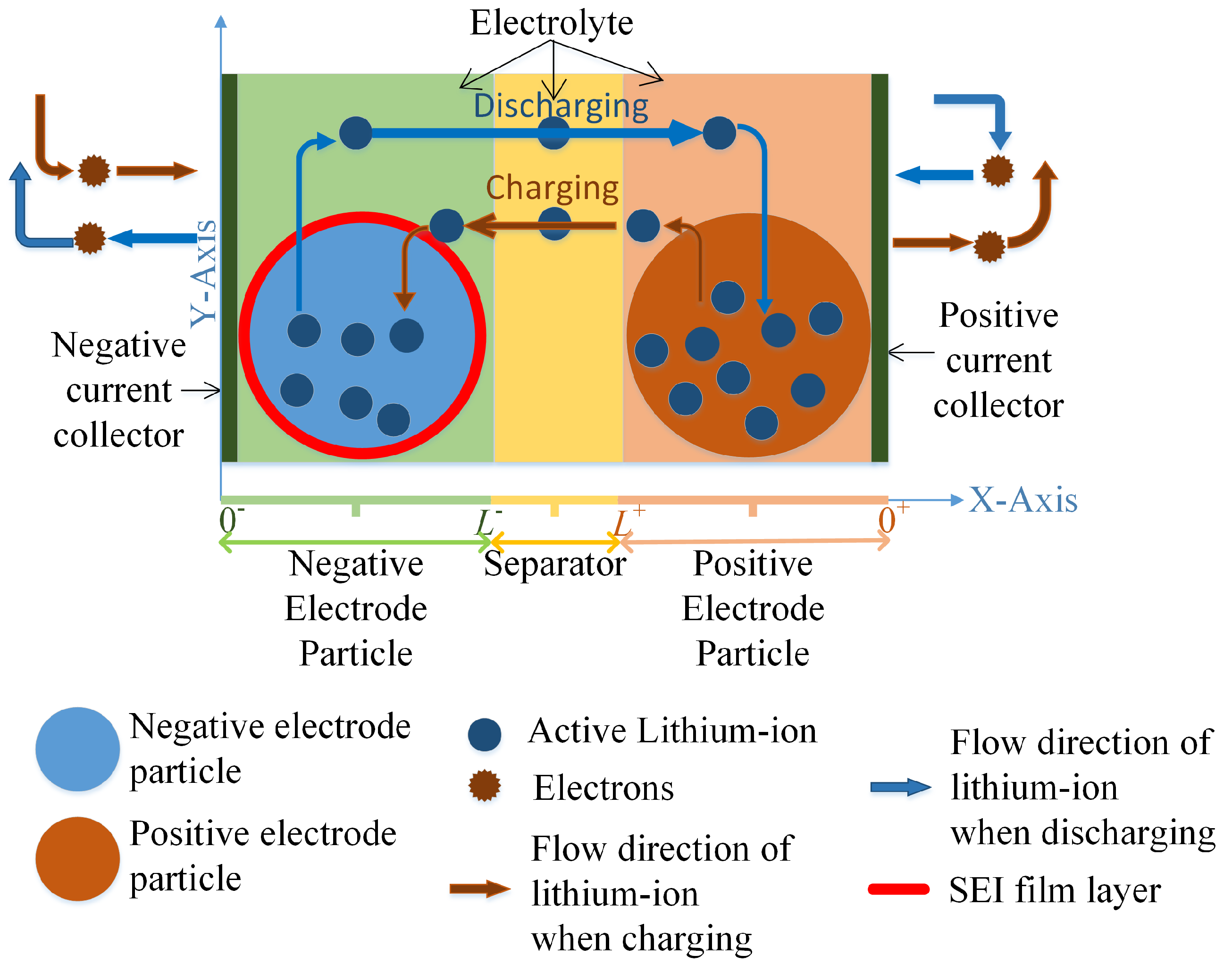
2.1. Electrochemical Models

Due to their relative simplicity, ease of implementation, and low computational overhead, empirical and equivalent circuit models (ECMs) of battery cells have often been adopted in commercial BMSs. However, these models often do not consider the changing operating conditions of the cells and the nonlinearities of the electrochemical processes occurring within the cells. Such operating conditions and nonlinearities will in turn result in changes in the parametric values of the model parameters. Therefore, a BMS incorporating these models can lead to reduced reliability and safety of the BESS operations [2].
In contrast, the electrochemical battery models provide detailed insights into the cell’s internal dynamics, enabling the internal battery states such as the battery SOC and SOH to be estimated accurately. Doyle et. al. has developed the physics-based two-dimensional (P2D) model based on the concentrated solution and the porous electrode theories to describe the dynamics of the electrochemical reactions inside the battery cells [32]. However, the coupled nonlinear partial differential and algebraic equations in the P2D model increase the model complexity and hence the computational burden, making it unsuitable for use in the real-time control application of the battery [33].
In view of the modelling difficulty, considerable efforts have been applied to simplifying the P2D model further. Towards this end, novel models such as the reduced-order electrochemical physics-based equivalent circuit models have been developed and have been shown to be able to replicate the behaviour of the cell’s internal dynamics with sufficient accuracy but at much lower computational effort than the P2D model [8,34].

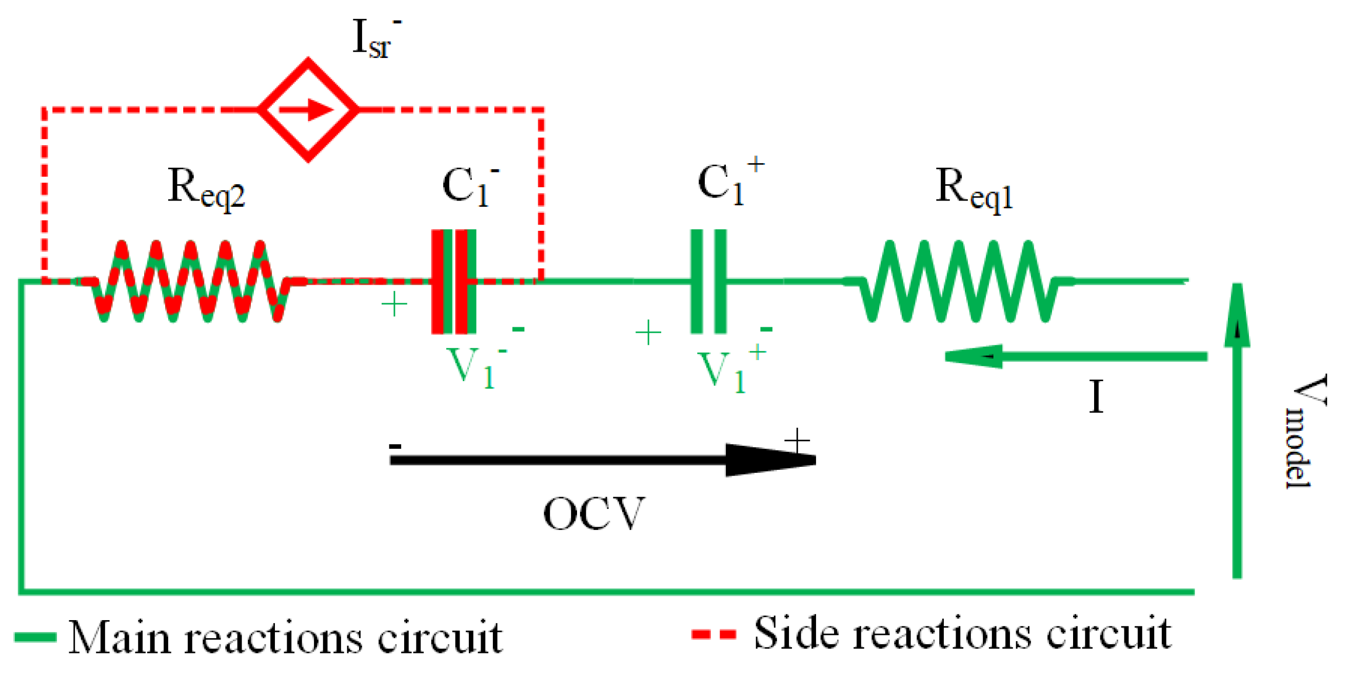
2.2. Reduced-Order Equivalent Circuit Model

The reduced-order equivalent circuit model (ROECM) developed in [8] is derived from the single particle model (SPM), a simplified version of the electrochemical battery model. ROECM takes advantage of well-established electric circuit theory and the strength of cell electrochemical model. It is scalable and sufficiently accurate for up to a 1C rate operating condition. With the assumed negligible spatial variations in the Li-ion concentration, ROECM is computationally efficient because the partial differential equations contained in the P2D model can be replaced by ordinary differential equations. Moreover, a most attractive feature of the ROECM is that it provides physical interpretation to the circuit parameters and the internal state variables. Readers are invited to read [8] for further information.
According to the literature, the side reactions in the positive electrode are usually negligible compared to the side reactions in the negative electrode [3]. Hence, the cell resistance ( R eq ) increases with the degradation due to the increase in SEI film resistance ( R f ) in the negative electrode. The ROECM allows estimation of the battery SOC and SOH to be readily obtainable, as detailed in [8]. Please refer Appendix A for SPM and ROECM schematic diagrams and governing equations.

3. A Reconfigurable Li-Ion Battery Pack

3.1. Topology

As explained in Section I, MMSPC [15] provides a battery pack the ability to dynamically switch battery cells into series, parallel, bypass, or a combination of these connections [18]. It thus increases the degree of freedom to rearrange the cell configurations in the battery pack in real time [35]. Figure 1 shows the proposed three-phase BESS with a five-layer battery pack arrangement. The five layers are in order of cell, block, sub-bank, bank, and phase. MMSPC is implemented at block level to achieve cell level management. Table 1 shows the parameters of the proposed three-phase BESS. Figure 2 shows a block of cells with N number of modules. Each module is shown to contain a battery cell and an MMSPC converter. Through the open-and-close combination of the switches S 1 S 8 , there are seven possible interconnection states between the modules M k and M k + 1 such that a short circuit between the k t h and k + 1 t h cells can be avoided [18,35]. It is through this flexibility in the interconnections between the modules that one can control the loss of energy storage capacities and the increase in the SEI film resistances in the cells. The corresponding ON and OFF position for the seven interconnections are provided in Figure 2 and are as follows: series positive (s+), series negative (s−), bypass positive (b+), bypass negative (b−), parallel positive (p+), parallel negative (p−), and zero (0).
In this work, the phase shift-pulse width modulation (PS-PWM) scheme is used to determine the switching command in configuring the module interconnection states. In Figure 2, L k is the intermediate interconnection state between the M k and M k + 1 modules, whereas L N is the termination interconnection. A triangular carrier waveform W k is assigned to k t h module, and the phase shift between the adjacent carrier waveform is Φ k = ( 360 / ( 2 N ) ) ( k 1 ) , k = ( 1 , 2 , , N ) as shown in Figure 5a. The sinusoidal reference signal, V ref , is compared against ± C k to obtain L k or L N . The logical rules used to determine L k and L N are as follows:
L k = s + ; V ref ( t ) | C k ( t ) | s ; V ref ( t ) | C k ( t ) | p + ; C k ( t ) < V ref ( t ) C k ( t ) p ; C k ( t ) < V ref ( t ) C k ( t ) .
L N = s + ; V ref ( t ) | C n ( t ) | s ; V ref ( t ) | C n ( t ) | b + ; C n ( t ) < V ref ( t ) C n ( t ) b ; C n ( t ) < V ref ( t ) C n ( t ) .
For example, s+ is activated for interconnect L k when V ref is higher in magnitude than both the C k and C k . Other switching patterns can be similarly obtained by following (1) and (2), as shown in Figure 5b–e.

3.2. Energy Losses in the Pack

The power switches in the MMSPC are nonideal, as they have limited power-handling capacity, finite on/off-state resistance, and limited switching speed. Hence, during the MMSPC operation, these will lead to switching, conduction, and parallelization losses and the consequent temperature increase in the modules, as well as voltage and charge imbalances in the battery pack. As a result, cells in a battery pack are subjected to varied operating conditions, leading to uneven degradation between the cells. Therefore, the losses are important considerations, and they need to be minimized.
Switching losses ( E loss , sw ) are proportional to the switching frequency and to the number of switching transitions [15]. Switching losses per module can be determined using (3).
E loss , sw , t = ( 1 / 2 ) δ k V k I k ( t on + t off )
where, δ k is the number of switching transitions, V k and I k are the voltage and current of the k t h module, t on and t off are the turn-on and turn-off times of the semiconductor switch, respectively, over the time period Δ t .
Conduction losses ( E loss , cd ) are due to the voltage drop across the power switches and the cell’s internal resistance. Over time interval Δ t , E loss , cd is calculated using the forward voltage drop V ce , u and current I u of the u t h semiconductor switch, the equivalent resistance R EQ of the pack, and the current I load as in (4).
E loss , cd = u V ce , u I u + R EQ I load 2 Δ t
With the total resistances of the series- and parallel-connected modules denoted as R s and R p , respectively, R EQ can be obtained from the following:
R EQ = ( R p + R s )
R p = g = 1 n p ( 1 / j n g p 1 / R j )
R s = j = 1 n s R j
Here, n p and n s are the number of parallel- and series-connected sets of modules in the pack, whereas n g p is the g t h parallel-connected set of modules in the pack where g 1 , 2 , 3 , , n p . R j is the cell resistance of the j th module.
Parallelization losses ( E loss , pr ) are due to unequal initial open-circuit voltages between two or more parallel-connected modules [15]. It is calculated using the equivalent capacitance ( C eq ) and the voltage difference ( Δ V ) for a parallel connected set of modules, as shown in (8). The sets of modules with the smallest voltage difference should be connected in parallel to minimize parallelization losses. However, the individual module capacitance C tends to decrease with the degradation due to the capacity loss in the cell [8].
E loss , pr = ( 1 / 2 ) C eq Δ V 2
Δ V 2 = g = 1 n p j n g p a n g p : j < a ( V cell , j V cell , a ) 2
where V cell , j and V cell , a are the measured voltages of cells in modules j th and a th which are elements of the set of parallel-connected modules n p g .

4. Control Mechanism

Control and management of the BESS is governed by its ABMS, the high level schematic diagram of which is shown on Figure 3. The ABMS is composed of an electrochemical battery model, i.e., the ROECM described in Section 2.2 and a scheduler. Based on the measured cell input current, temperature, and cell electrochemical parameters, the ROECM allows the cell voltage and other state variables, including the S O C ( t ) and S O H ( t ) to be determined. In this work, the cell S O C ( t ) and S O H ( t ) are defined in the same manner as in [8], i.e., the ratio between the cell’s positive electrode available capacity to the cell capacity at beginning of life (BOL) and the ratio between the cell’s remaining capacity to the cell capacity at BOL, respectively viz:
S O C ( t ) = ( q + ( t ) q loss ( t ) ) / q max , 0
S O H ( t ) = ( q max , 0 q loss ( t ) ) / q max , 0
where q + ( t ) is the positive electrode capacity, q loss ( t ) is the capacity loss, and q max , 0 is the cell capacity at BOL.
Next, the scheduler identifies the optimal cell arrangement intended to minimize both the capacity and energy losses of the pack. In this work, two possible approaches to the scheduler design are considered and compared. These approaches are based on the multiobjective and hierarchical optimization procedures and are described in Section 4.1.1 and Section 4.1.2, respectively.
At the input of the ABMS, a phase-locked loop (PLL) and a current controller are used to synchronize the battery pack terminal voltage to the grid voltage. The voltage reference waveform is then fed to the PS-PWM modulator in which the output level command is obtained using the logical rules (1) and (2). The obtained output level command (OLC) is sent to the scheduler to identify the required number of modules that need to be connected in the series to produce the power/voltage requirement. The estimated SOC, SOH, and the energy loss information are also fed to the scheduler to perform the optimization, and as a result, the optimal configuration command is identified among all the possible connection arrangements. In this way, the battery block reconfigures the cell arrangement so that the required block terminal voltage and power are met.

4.1. Scheduler Functionality

4.1.1. Multiobjective Optimization-Based Scheduler

Multiobjective optimization (MOO) can be used to determine the optimal switching configuration commands to reconfigure cells in the battery block. The two main objectives are to minimize capacity loss and energy loss across a given time horizon t { 1 , 2 , , T } .
The decision variable in this multiobjective optimization is the choice of switching configuration command sequence ξ = ( ξ 1 , ξ 2 , , ξ T ) from the set of all possible command sequences ϕ . An element ξ t of the command sequence ξ represents a module configuration command at time step t, with ξ t , i { s + , s , p + , p , b + , b } giving the individual interconnection command for cell i { 1 , 2 , , N } . ξ t , i represents how cell i connects to cell i + 1 or the termination interconnection for cell N. Thus, the minimization of the total capacity loss of the battery pack ( Q loss ) over a time step t can be expressed by the following function:
min Q loss = min ξ ϕ t = 1 T i = 1 N q loss , i ( t | ξ t )
In (12), q loss , i ( t | ξ t ) is the capacity loss of the i t h cell over time step t when operating under module configuration command ξ t .
The total energy loss of the battery pack ( E loss ) can be obtained by adding the switching loss (3), conduction loss (4), and parallelization loss (8) of all the modules. The objective of minimizing the total energy loss can be expressed as follows:
min E loss = min ξ ϕ t = 1 T ( k = 1 N ( 1 / 2 ) δ k , t ( ξ t 1 , ξ t ) V k , t ( ξ t , I load , t ) I k , t ( ξ t , I load , t ) ( t on + t off ) + R EQ , t ( ξ t ) I load , t 2 Δ t + g = 1 n p ( ξ t ) ( 1 / 2 ) C eq , g ( ξ t ) Δ V 2 ( ξ t ) )
In this optimization process, I load , t for t = 1 , , T is the input parameter. Any variable which can be calculated for a given ξ t is represented as a function of ξ t . ξ 0 is the initial state where all the switches are turned open. It is assumed that the cell voltages are always maintained within the respective upper/lower cutoff voltages. This is done in order to prevent the over-charging/discharging of the cells and to ensure the safe operation of the cells. It is also assumed that the input current to each module is maintained at less than 1C because for grid-connected battery banks, their input current tends to be below this level.
Therefore, the minimization of the total capacity loss and energy loss of the pack depends on ξ t . In this work, ξ t is determined by applying MOO and subsequent use of its Pareto front. In general, the technique combines two or more independent objective functions and identifies a set of nondominated solutions from the search space, termed the Pareto frontier. The Pareto frontier set consists of all solutions for which one objective cannot be improved without detriment to the other objective. In the context of the present investigation, the Pareto frontiers are identified by considering the Equations (12) and (13) as the main objectives. All possible connectivity arrangements between the modules and over a quarter cycle of the sinusoidal reference waveform are considered in the search space ϕ . Let N denote the number of modules and n the number of cell voltage levels needed to obtain the required voltage output. Then, the total number of sequences are equal to Π r = 0 n N C r .
The step-by-step procedure for the MOO-based scheduler is shown in Figure 4. First, the scheduler gathers the data required for execution. The modes of operations are charging and discharging, and four modules are considered in this study. For such an arrangement and over a complete mains frequency cycle, ( Π r = 0 4 4 C r ) 4 = 84 , 934 , 656 , different switching sequences can be identified to produce a nine-level sinusoidal waveform with the maximum allowable peak-to-peak voltage that the four cells can generate. Therefore, to reduce the curse of dimensionality, a quarter cycle is chosen as the time horizon. Hence, with Π r = 0 4 4 C r = 96 , different switching sequences can be identified, as shown in Figure 5, and constitute ϕ . According to the voltage levels, Figure 5 shows the MMSPC cell arrangement with the interconnections introduced in Section 3.1. To present a better visualization, cell configuration schematics for sequence 96 are shown in the figure. In Figure 5f, the graph shows the nine-level waveform generated by the modulator and the pack output voltage. As mentioned in Section 1, the capacity fade is primarily due to the SEI film formation in the negative electrode during charging. Therefore, for each ξ , when the mode of operation is charging, both capacity and energy losses are to be minimized. Hence, both (12) and (13) objectives need to be satisfied. Whereas, when the mode of operation is discharging, only (13) needs to be satisfied as only the energy losses are presented in the pack. For objective (12), the total capacity of the pack is found for the considered time horizon. Similarly, for objective (13), the total energy loss is found by the addition of switching, conduction, and parallelization losses using (3), (4), and (8). Once the total capacity loss and energy losses are calculated for all ϕ , the dual objective data matrix ( 96 × 2 ) is created. In this way, the Pareto frontier set is identified, and the switching sequence which gives the minimum capacity and energy losses is chosen as the Pareto optimal solution. If there is no obvious solutions in the identified Pareto frontier set, the dual objective data matrix is normalized, and the switching sequence which has the minimum normalized Euclidean distance from the utopia point (i.e., a hypothetical solution where the optimal value for each objective can be achieved concurrently) is chosen as the Pareto optimal switching sequence. Then, this sequence is used as the optimal switching configuration command.

4.1.2. Modified Hierarchical Optimization-Based Scheduler

As the Li-ion battery’s capacity fading is a relatively slow process, unlike the MOO approach described earlier, a hierarchical optimization procedure could be a possible alternative approach to determine ξ t . In the hierarchical approach, the capacity loss minimization is to be performed over a predefined time horizon while the minimization of the pack energy losses is to be carried out over every switching time step. Although a hierarchical optimization for energy loss minimization has been proposed in [18], in the present work, the hierarchical optimization procedure has been modified to include the capacity loss minimization as the first objective in the hierarchy.
An example flow diagram for hierarchical optimization is shown in Figure 6. In the figure, SOH levels and cell resistances from the battery model and the measured cell voltages are taken as inputs for the scheduler. Then, hierarchically, cell configurations identified as possibly not satisfying the corresponding criteria are eliminated. The eliminated sequences are outlined in red, and the sequences that are carry forward to the next level are outlined in green in the decisions column.
In level 1, to minimize capacity loss, the scheduler observes the output level command from the modulator and the battery pack’s present SOH. By analysing these inputs, at first, the scheduler sorts the individual cells by their SOH. Then, it generates all possible switching configuration commands by rearranging the modulator output level command (OLC) for time step t: θ t 1 = { ψ t : ψ ξ } . Next, the scheduler identifies a set of feasible switching configurations from θ t 1 and gives priority to higher SOH cells to be connected in series. Suppose the modulator OLC is (p+, s+, p+, s+) as in Figure 6. For the aforementioned OLC, there are six possible switching configuration commands for θ t 1 (S1, S2, S3, S4, S5, S6), and three of them are selected as θ t 2 (S1, S2, S3) based on the individual cell SOH within level 1 of the hierarchy.
In level 2, to minimize switching loss, the number of switch transitions per changing state needs to be minimized within time step t [18]. The number of switch transitions per change in interconnection δ ( ξ t 1 , i , ψ t , i ) is given in (14).
δ ( ξ t 1 , i , ψ t , i ) = 0 , no change in states from L 8 , s + s o r s s + 4 , all other possible transitions .
Here, ξ t 1 , i is the previous switching state of the i th cell configuration command and ψ t , i is the i th feasible switching state of the switching configuration commands in θ t 2 where ξ t 1 , i { s + , s , p + , p , b + , b } and ψ t , i { s + , s , p + , p , b + , b } . Since the total number of switch transitions for the battery pack is to be minimised, the scheduler observes ξ t 1 , i and carries forward the switching configurations in θ t 2 , which satisfy the following objective function (15).
min S l o s s , t = min ψ t θ t 2 i = 1 N δ ( ξ t 1 , i , ψ t , i )
Therefore, S1 and S2 are carried forward to the next level, and S3 is eliminated as it contributes to the highest switching transitions.
In level 3, cell resistances are taken as the inputs to minimize the conduction loss. As the voltage drop due to the power switches cannot be avoided, the only way to achieve minimum impedance is to select an optimal configuration of the series-parallel combinations of the modules within the pack [15]. Based on this, the scheduler selects configurations in θ t 3 which have the least equivalent resistance R E Q , as expressed by the objective function (16).
min C l o s s , t = min ψ t θ t 3 R E Q ( ψ t )
In the final level, to minimize parallelization loss, the scheduler similarly selects the module configuration which has the least voltage difference between the parallel-connected cells in θ t 4 . The objective function for parallelization loss is expressed as (17).
min P l o s s , t = min ψ t θ t 4 Δ V 2 ( ψ t )
Finally, the configuration which is not eliminated is chosen as the module configuration command. Therefore, out of S1 and S2, S1 is selected as ξ t , as it contributes least to the parallelisation losses.

5. Advanced Battery Management System Design

The proposed system utilises the MMSPC topology to interconnect multiple storage elements and change their connection configuration regularly. The chosen storage elements were connected to a MMSPC built using MOSFETs. The proposed solution ensures a physically small and modular design focusing on scalability. The control system was designed on a layered master–slave arrangement where each layer controller is responsible for a number of slave controllers. At the block level, a motherboard manages N daughterboards that were wired together and regulated in order to supply the MOSFET drivers with communication, power, and switching sequence. Each cell needs a converter module; thus, the daughterboards were built with a compact footprint to ensure dense storage capacity matching the small format Li-ion package (18650) [36].
Figure 7 outlines the design overview and responsibilities of the daughterboard and motherboard modules in order of priority with physical connections and mappings outlined by the connecting traces. The motherboard was assigned to perform modulation, scheduling, and optimisation algorithms. The modulator uses the the phase shifted PWM and the reference voltage waveform generated by the phase-locked loop (PLL) and the current controller to generate the output level command (OLC), and the scheduler uses the OLC to generate the module configuration command after taking the proposed optimization technique into consideration. To guarantee that the computational challenges of the optimisation methods are solved locally in an acceptable amount of time, the motherboard was fit with a high-performance processor. The daughterboard controller was assigned to switching MOSFETS; sensing the voltage, current, and, temperature of the cells; identifying parameters; and estimating states using the cell electrochemical model. The interintegrated circuit (I2C) protocol was chosen as the primary communication method between the motherboard and daughterboards. The communication is conducted in the form of data packets by sending a general all-call command to all daughterboard modules to update the switching states. Due to the inherent delay in receiving the general all-call by the daughterboards, a fixed time delay was included to compensate for the delay and ensure MOSFETs’ consistent switching. State estimation completed in daughterboards uses the amount of time left between switching state updates [36].

6. Simulation and Experimental Validation

Simulations were conducted in MATLAB Simulink simulation environment on a PC with an Intel Core i7-8700 CPU @ 3.2 GHz and 16 GB RAM with a continuous solver selected. For the experiments, the test setup shown in Figure 8 was used with four 18650 L i F e P O 4 cells with 1.6 Ah capacity. Other properties of the cells are listed in Table A3 in the Appendix A.
The hardware circuit design was simulated in LTspice and designed using KiCAD software. The boards were hand assembled and individually tested for mechanical and electrical failures. The system was tested with four Li-ion cells with each cell connected to a daughterboard accompanied by a motherboard as shown in Figure 8. ARM cortex M4 STM32 microcontrollers were used for the motherboard and daughterboard processors which have multiple ADC’s, GPIOs, and hardware abstract layer (HAL) drivers for rapid prototyping. In each daughterboard, two sets of full-bridge MOSFET arrays are used for MMSPC. The MOSFET switching is handled by the MIC4606-2YTS-TR driver IC with 4 kHz switching frequency. The PCB traces of the MOSFET driver circuits were optimised for a shorter distance, cross-talk avoidance, and high current capability. Hall effect current sensors, a voltage divider, and a low pass filter are used to measure the cell currents and voltages respectively. To achieve a small footprint and a low-cost design, surface-mounted devices are used in the boards. The circuits are protected using 3A slow-blow fuses and current sensors with an inbuilt re-settable 5A fuse for overload conditions.
The system firmware was designed using low-level HAL and an interrupt-driven system for optimal performance and actuation timing. In the motherboard, the switching states are sent via an I2C interrupt which utilises a buffer storage system. The I2C state estimation data request uses direct memory access to reduce the CPU processing time. The remaining time is utilised by the optimization algorithm which is run in a real-time operating system, allowing for coherent and multitasking functionality for real-time response and long-term background processing. The daughterboards use an interrupt priority control scheme to update the switching states accurately, calculate the cell states, and estimate the parameters. A failure detection function was established which is able to identify the failure type, such as battery over/under voltage/current or communication failure, and execute the respective action to fix or prevent further damage to the system.
The battery block output voltage and current were observed across a resistive load, as shown in Figure 9. The output voltage of the block clearly shows the nine switching-state voltage levels produced by four cells, similar to that of Figure 5f, with pack output voltage indicating the preciseness of the motherboard and daughterboard functionalities.
For the simulation and experimental studies, a medium voltage BESS which is used to smoothen the output power of a hypothetical 300 kW wind farm was considered. The objective of the study was to check the proposed ABMS and control strategy’s performance under varying current profiles. Therefore, a set of wind speed data over an hour was taken from [37] to generate the hypothetical wind farm data. The output power of the wind farm data was smoothened with the BESS and dispatched to the grid. The difference between the generated wind power and the dispatched power to the grid was considered to be the input power to the BESS, as shown in Figure 10.

6.1. Electrochemical Battery Model Validation

In this subsection, the MATLAB simulated ROECM is compared with the actual cell terminal voltage and daughterboard embedded cell model. Relatedly, the 1500 s long power profile can be seen in Figure 10. Accordingly, the current profile is obtained for a monolithic BESS assuming all the cells are identical and are connected in fixed series configuration, with each cell represented by a ROECM. Figure 11c shows that the actual cell measurement is in excellent agreement with the ROECM simulated in MATLAB and embedded in the daughterboard. Moreover, the simulated state estimation and capacity loss estimation were compared with those of the daughterboard estimations and match excellently, as shown in Figure 11d,e. Therefore, the implemented cell state estimation algorithm in the daughterboard is identical to MATLAB’s simulated ROECM and in better agreement with the actual cell measurements.

6.2. Scheduler Performances

In this subsection, experimental and simulated studies are presented for the proposed RBP with MOO based scheduler. It is compared against RBP with a Modified Hierarchical Optimization (MHO) based scheduler and also with a Monolithic Battery Pack (MBP). The RBP is considered as a four module battery block with MMSPC and MBP is considered as a fixed series connected four cell battery block. The cells in these battery packs are assumed to be identical initially and their losses are compared in Figure 12a,c. It can be seen that the MOO and MHO based schedulers give minimum capacity loss, however the MBP losses are comparatively high. Moreover, the MOO based scheduler gives less energy loss compared to RBP with MHO. In Figure 12b,d, the cells are assumed non-identical. The cell 1 is set to degrade faster than the other three cells. In that scenario, the effectiveness of the MOO and MHO strategies are significant compared to that of MBP. Significant reduction in battery pack energy loss can be observed in MOO strategy.
Figure 13 shows the experimentally obtained cell voltages for identical cells. According to the results, cell voltages were well balanced through out the test period.

7. Discussion

The integration of the scheduler function improves the battery SOH and decreases the converter losses. The scheduler with MOO identifies the most appropriate switching sequence according to the health and the converter losses in the battery pack, and therefore provides more optimal results compared to the other two mechanisms. This shows the effectiveness of the reconfiguration of the battery pack in managing the inherent cell inconsistencies in applications such as using second life batteries in BESS.
The selection of switching sequences in MHO strategy was compared with the proposed MOO strategy for the first 1500 s. It can be seen that the switching sequence chosen by MHO strategy is different from the Pareto optimal switching sequence obtained using MOO, as shown in Figure 14. In Figure 14a,b, the switching sequence change over a 1500 s operation period and its extraction of 250 s are presented, respectively. As mentioned in Section 1, the capacity fade is primarily due to the SEI film formation in the negative electrode during charging. Therefore, during charging, the distribution of sequences in the Pareto analysis is two-dimensional, as shown in Figure 14c,d, whereas during discharging, it is one-dimensional, as shown in Figure 14e,f.
In Figure 14c,e, the Pareto analysis is shown for identical cells under charging and discharging modes, respectively. When cells are in charging mode, the set of Pareto frontiers are identified as in Figure 14c. Therefore, sequence 37 is chosen as the Pareto optimal configuration command, as it has the minimum Euclidean distance from the utopia point. When cells are in discharging mode, sequence 1 is identified as the only Pareto optimal sequence which provides the minimum energy loss. However, in both cases, sequence 92 is identified as the optimal switching sequence by the MHO scheduler. In Figure 14d,f, the Pareto analysis is shown for nonidentical cells under charging and discharging modes, respectively. Similarly, a set of Pareto frontiers are identified, as shown in Figure 14d. In this scenario, sequence 1 is chosen as the Pareto optimal configuration command by the MOO scheduler while sequence 25 is identified by the MHO scheduler. In Figure 14f, it can be seen that sequence 1 is identified by both schedulers as the optimal configuration command under discharging mode. Even if the sequence was the same according to both schedulers in this case, it is apparent that this is not always the case. The distance between the chosen sequences by the two schedulers and the accumulated difference in the respective losses result in the deviation in capacity and energy losses in the proposed optimization methods.
The advantage in MOO is that the switching sequence for the next quarter cycle is identified at the beginning of the quarter cycle, but in MHO, the switching command is identified for each switching step at the beginning of the step. Therefore, as MOO provides a larger search space for optimization over MHO, it naturally presents a switching sequence producing an improved outcome. It is interesting to observe how the battery pack reconfigures its arrangement with respect to current operating conditions to deliver a better performance.
The efficiency analysis for the proposed two optimization methods are presented for identical and nonidentical cell scenarios in Table 2. Accordingly, the MOO scheduler provides higher efficiency compared to the MHO scheduler in all scenarios.
The proposed degradation and energy loss conscious ABMS with the MOO-based scheduler provides following advantages:
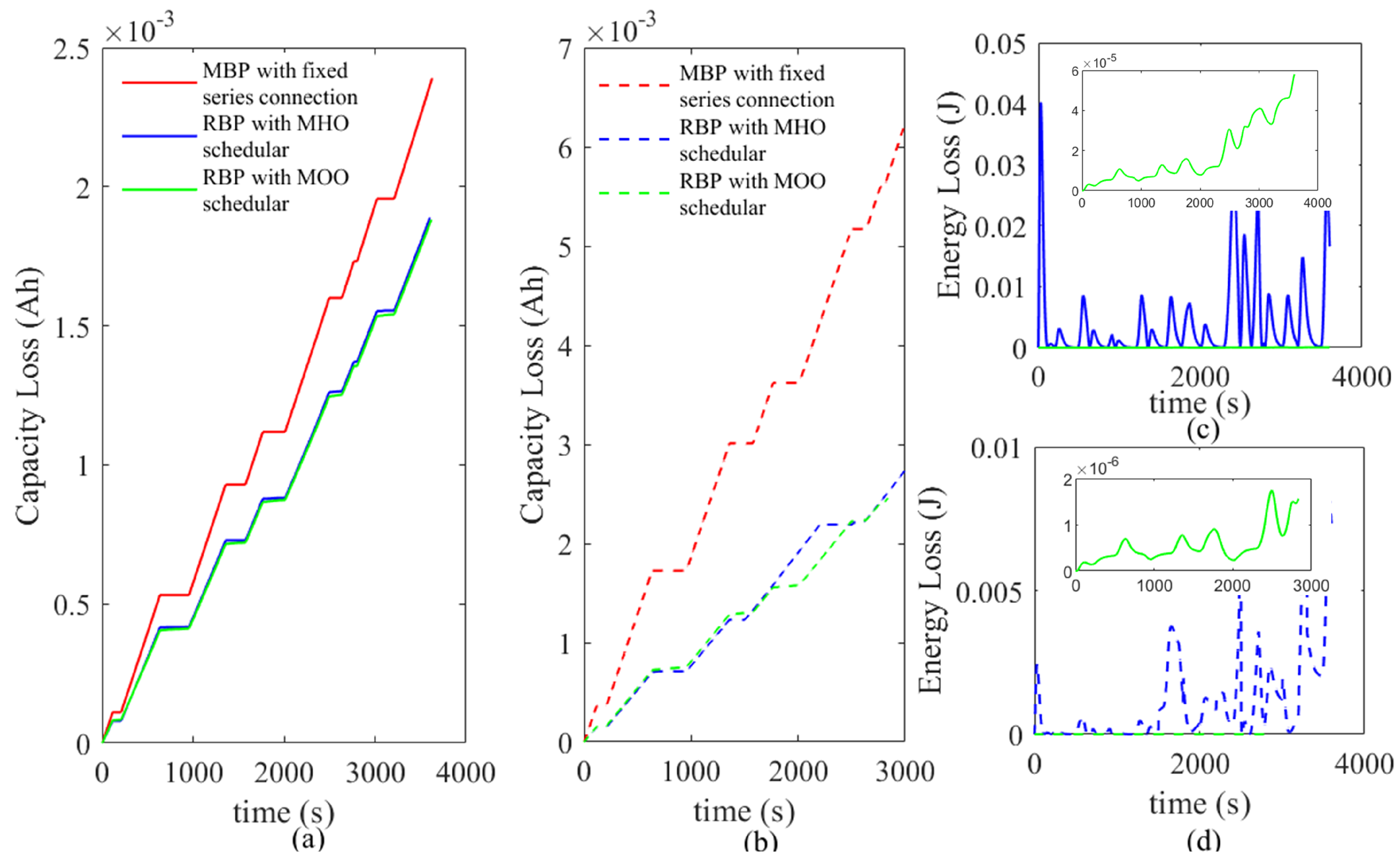
  • The pack capacity loss is reduced by 28% and 58% for identical and nonidentical scenarios, respectively, compared to MBP, suggesting that the proposed method is ideal for battery packs with cell inconsistencies.
  • The energy loss in the converter is reduced by 98% while efficiency is increased by nearly 5% for identical and nonidentical scenarios, respectively, compared to the MHO scheduler.
  • The SOC balancing is achieved with a maximum difference of 0.01, indicating that the maximum cell utilization can be achieved without limiting the pack’s performance to its weakest cell due to the adaptive nature of the control mechanism to the changes in the cell condition and dynamic reconfiguration.
  • The distribution of computational requirements between the daughterboard and motherboard allows for reduced cost, less time, and increased accuracy. State estimation and ADPE are performed by the daughterboard within 200 μ s and 0.4902 s, respectively. The scheduler function is performed by the motherboard within 0.005 s.
  • A feasible hardware design is proposed which ensures a physically small and modular design with a focus on scalability. The daughterboard modularity allows for the system to scale according to the application requirement.

8. Conclusions

In this paper, a degradation and energy loss control mechanism with MOO and MHO strategies is proposed to reduce the rate of capacity loss and energy loss of an RBP-fed grid interfacing with MMSPC. These decentralized and layered control mechanisms were developed for cell-level management to maximize cell utilization through dynamic reconfiguration of the modules. The following crucial outcomes were attained since, as the primary contribution of this study is to suggest a reconfiguration of cells that can account for inconsistencies caused by degradation:
  • The proposed RBP utilizes a control mechanism that identifies the optimal cell configuration by taking cell inconsistencies and electrochemical parameter variations into account.
  • The utilized physics-based battery model is computationally efficient and provides physical interpretation to the circuit parameters and the internal state variables. It allows for the accurate estimation of the battery SOC and SOH.
  • The monitoring and control of individual cells is achieved by using MMSPC, which has the ability to dynamically switch battery cells into series, parallel, or a combination of these connections.
  • The ABMS proposed has the ability to incorporate cell inconsistencies, accurate online estimation of cell states, and electrochemical parameters.
  • A feasible hardware design for the control scheme is presented, and the comparison of the proposed strategies, with simulation and experimental results, is reported and discussed.
Future work will be focused on integrating the temperature dependency with the proposed MOO scheduler to minimize heat generation and temperature increase in the battery pack via reconfiguration. For this purpose, a thermal management system needs to be incorporated to the proposed ABMS to estimate the internal temperature of the cells using minimum cell measurements.

Author Contributions

Conceptualization, D.K., M.V., Y.M. and P.C.; methodology, D.K.; software, D.K.; validation, D.K.; formal analysis, D.K.; investigation, D.K., M.V. and P.C.; resources, M.V., Y.M., T.F. and P.C.; data curation, D.K.; writing—original draft preparation, D.K.; writing—review and editing, M.V., Y.M., P.C., T.F. and S.S.C.; visualization, D.K.; supervision, M.V., Y.M., P.C., T.F. and S.S.C. All authors have read and agreed to the published version of the manuscript.

Funding

This research received no external funding.

Data Availability Statement

Data will be available upon request.

Conflicts of Interest

The authors declare no conflict of interest.

Abbreviations

The following abbreviations are used in this manuscript:
ABMSadvanced battery management system
BESSbattery energy storage system
BOLbeginning of life
BMSbattery management system
CHMMCcascaded H-bridge modular multilevel converter
I2Cinterintegrated circuit
Li-ionLithium-ion
MMCmodular multilevel converter
MMSPCmodular multilevel series parallel converter
MOOmultiobjective optimization
MHOmodified hierarchical optimization
MBPmonolithic battery pack
OCPopen circuit potential
OCVopen circuit voltage
OLCoutput level command
PLLphase-locked loop
PS-PWMphase-shifted pulse width modulation method
P2Dpseudo-two-dimensional
RBPreconfigurable battery pack
ROECMreduced order equivalent circuit model
SEIsolid electrolyte interface
SOEstate of energy
SOHstate of health
SPMsingle particle model
SEIsolid electrolyte interface
SOCstate of charge

Appendix A

Appendix A.1. Electrochemical Models and Governing Equations

Figure A1. Single particle model (SPM) cell anatomy of the Li-ion battery.
Batteries 09 00217 g0a1
Figure A2. Reduced-order equivalent circuit model (ROECM) of the Li-ion battery showing the main and the side reactions circuits [8].
Batteries 09 00217 g0a2
Table A1. Model Equations.
SPMROECM
Potential in the solid phaseEquivalent resistance of the cell
Φ s + ( t ) = 2 R T F s i n h 1 ( I ( t ) 2 a + L + r eff + ( c e 0 c ss + ( t ) ( c s , max + c ss + ( t ) ) ) + U ( c ss + ( t ) ) + R f + I ( t ) ) ( a + L + ) R eq = R col + 7 R 1 + + R η + + R f + + R e + R f + 7 R 1 + R η
SEI film resistance
R f ( t ) = M f ρ f κ f F a 0 t J sr ( τ ) d ( τ ) + r f , 0
Φ s ( t ) = 2 R T F s i n h 1 ( I ( t ) 2 a L r eff ( c e 0 c ss ( t ) ( c s , max c ss ( t ) ) ) + U ( c ss ( t ) ) + R f I ( t ) ) ( a L ) Capacity of the positive electrode
q + ( t ) = A L + F ϵ s + c s , max + ( θ 0 % + θ s , avg + ( t ) ) 3600
Lithium ion concentration in the solid particlesCapacity of the negative electrode
c s + ( r , t ) t = 1 r 2 r ( D s + r 2 c s + ( r , t ) r ) , c s ( r , t ) t = 1 r 2 r ( D s r 2 c s ( r , t ) r ) q ( t ) = A L F ϵ s c s , max ( θ 100 % θ s , avg ( t ) ) 3600
Boundary conditions andCapacity loss of the cell
c s r | r = 0 = 0 , c s r | r = 0 = 1 D s j n , c s ( x , r , 0 ) = c s 0 q loss ( t ) = 1 3600 0 t I sr ( τ ) d τ + q loss , 0
Molar flux
j n + = I ( t ) F a + L + , j n = I ( t ) F a L
Output voltage of the cell
V ( t ) = Φ s + ( t ) Φ s ( t ) I ( t ) R col
Table A2. List of Symbols.
Φ s Electric potential in the solid phase
RUniversal gas constant
TCell temperature
aSpecific interfacial area
r eff Reaction rate constant
c e 0 Lithium ion concentration in the electrolyte at t = 0
c ss Lithium ion concentration in the solid phase particle surface
UEquilibrium potential of the reaction
c s Lithium ion concentration in the solid phase
rRadial dimension of the particle
D s Solid phase diffusion coefficient
j n Molar ion fluxes between the active material in the electrodes and the electrolyte
I sr Irreversible side-reaction current
R eq Equivalent resistance of the cell
R col Current collectors resistance
R 1 Resistance of solid phase over-potential due to Li-ion diffusion
R η Resistance due to the activation over-potential of the side reactions
R f Resistance due to the SEI-film formation
R e Electrolyte resistance
+Positive electrode
Negative electrode
ACross-sectional area of the cell
LWidth of the cell
FFaraday constant
ϵ s Volume fraction of the electrode
c s , max Theoretical maximum Li-ion concentration
θ s , avg ( t ) = c s , avg ( t ) / c s , max Volume-averaged stoichiometry at time t
θ 0 % Battery volume-averaged stoichiometry of the battery when it is fully discharged
θ 100 % Battery volume-averaged stoichiometry of the battery when it is fully charged
q loss , 0 Capacity loss of the battery at the beginning of life (BOL)
M f Average molecular weight of the electrode
ρ f Density of the electrode
κ f Conductivity of the electrode
r f , 0 Initial resistance of the SEI film of the electrode
J sr Irreversible side-reaction current density
Table A3. Battery Parameters.
Physical Meaning (Unit)Positive ElectrodeNegative Electrode
Particle radius (m) 2 × 10 6 2 × 10 6
Solid phase diffusion coefficient ( m 2 / s ) 1 × 10 14 3.9 × 10 14
Specific surface area of electrode ( m 1 ) 8.85 × 10 5 7.236 × 10 5
Length of the electrode (m) 80 × 10 6 88 × 10 6
Volume fraction of the solid phase 0.59 0.49
Theoretical maximum concentration in the solid phase ( mol · m 3 )51,55530,555
Stoichiometry for an empty battery at BOL0.950.03
Stoichiometry for a full battery at BOL0.48700.8851
Electrode rate constant ( A · m 2.5   · mol 1.5 ) 2.252 × 10 6 4.854 × 10 6
SEI film resistance at BOL ( Ω · m 2 )00.01
Effective electrolyte conductivity ( S · m 1 )0.00450.0113
Faraday constant (s· A/mol)96,487
Temperature (K)298.15
Universal gas constant [J/(K· mol)]8.314
Current collector resistance ( Ω · m 2 )0
Average Li-ion concentration in the electrolyte ( mol / m 3 )1000
Electrode plate area ( m 2 )0.05961
Average molecular weight of the SEI film (kg/mol) 7.3 × 10 4
SEI film density ( kg / m 2 ) 2.1 × 10 3
Exchange current density for side reaction ( A / m 2 ) 2.8 × 10 8   * / 2.8 × 10 7   !
Equilibrium potential of the side reaction (V)0.4
Charge capacity at BOL (Ah)1.6
Length of the separator (m) 20 × 10 6
Effective electrolyte conductivity of the separator ( S · m 1 )0.0563
* Value for all cells in identical cell scenario and value for cells 2, 3, and 4 for nonidentical cell scenario; ! Value for cell 1 in the nonidentical cell scenario.

References

  1. De Sisternes, F.J.; Jenkins, J.D.; Botterud, A. The value of energy storage in decarbonizing the electricity sector. Appl. Energy 2016, 175, 368–379. [Google Scholar] [CrossRef] [Green Version]
  2. Chaturvedi, N.A.; Klein, R.; Christensen, J.; Ahmed, J.; Kojic, A. Algorithms for advanced battery-management systems. IEEE Control. Syst. Mag. 2010, 30, 49–68. [Google Scholar]
  3. Vetter, J.; Novák, P.; Wagner, M.R.; Veit, C.; Möller, K.C.; Besenhard, J.; Winter, M.; Wohlfahrt-Mehrens, M.; Vogler, C.; Hammouche, A. Ageing mechanisms in lithium-ion batteries. J. Power Sources 2005, 147, 269–281. [Google Scholar] [CrossRef]
  4. Lawder, M.T.; Suthar, B.; Northrop, P.W.; De, S.; Hoff, C.M.; Leitermann, O.; Crow, M.L.; Santhanagopalan, S.; Subramanian, V.R. Battery energy storage system (BESS) and battery management system (BMS) for grid-scale applications. Proc. IEEE 2014, 102, 1014–1030. [Google Scholar] [CrossRef]
  5. Li, Y.; Vilathgamuwa, M.; Choi, S.; Xiong, B.; Tang, J.; Su, Y.; Wang, Y. Design of minimum cost degradation-conscious lithium-ion battery energy storage system to achieve renewable power dispatchability. Appl. Energy 2020, 260, 114282. [Google Scholar] [CrossRef]
  6. Hadigol, M.; Maute, K.; Doostan, A. On uncertainty quantification of lithium-ion batteries: Application to an LiC6/LiCoO2 cell. J. Power Sources 2015, 300, 507–524. [Google Scholar] [CrossRef] [Green Version]
  7. Meng, J.; Yue, M.; Diallo, D. Nonlinear extension of battery constrained predictive charging control with transmission of Jacobian matrix. Int. J. Electr. Power Energy Syst. 2023, 146, 108762. [Google Scholar] [CrossRef]
  8. Li, Y.; Vilathgamuwa, M.; Choi, S.; Farrell, T.W.; Tran, N.T.; Teague, J. Development of a degradation-conscious physics-based lithium-ion battery model for use in power system planning studies. Appl. Energy 2019, 248, 512–525. [Google Scholar] [CrossRef]
  9. Lucia, S.; Torchio, M.; Raimondo, D.M.; Klein, R.; Braatz, R.D.; Findeisen, R. Towards adaptive health-aware charging of li-ion batteries: A real-time predictive control approach using first-principles models. In Proceedings of the 2017 American Control Conference (ACC), Seattle, WA, USA, 24–26 May 2017; pp. 4717–4722. [Google Scholar]
  10. Lin, X.; Hao, X.; Liu, Z.; Jia, W. Health conscious fast charging of Li-ion batteries via a single particle model with aging mechanisms. J. Power Sources 2018, 400, 305–316. [Google Scholar] [CrossRef]
  11. Daowd, M.; Omar, N.; Van Den Bossche, P.; Van Mierlo, J. Passive and active battery balancing comparison based on MATLAB simulation. In Proceedings of the 2011 IEEE Vehicle Power and Propulsion Conference, Chicago, IL, USA, 6–9 September 2011; pp. 1–7. [Google Scholar]
  12. Chatzinikolaou, E.; Rogers, D.J. A comparison of grid-connected battery energy storage system designs. IEEE Trans. Power Electron. 2016, 32, 6913–6923. [Google Scholar] [CrossRef]
  13. Ahmad, A.B.; Ooi, C.A.; Ishak, D.; Teh, J. State-of-charge balancing control for On/OFF-line internal cells using hybrid modular multi-level converter and parallel modular dual L-bridge in a grid-scale battery energy storage system. IEEE Access 2018, 7, 131–147. [Google Scholar] [CrossRef]
  14. Quraan, M.; Tricoli, P.; D’Arco, S.; Piegari, L. Efficiency assessment of modular multilevel converters for battery electric vehicles. IEEE Trans. Power Electron. 2016, 32, 2041–2051. [Google Scholar] [CrossRef]
  15. Goetz, S.M.; Peterchev, A.V.; Weyh, T. Modular multilevel converter with series and parallel module connectivity: Topology and control. IEEE Trans. Power Electron. 2014, 30, 203–215. [Google Scholar] [CrossRef]
  16. Chatzinikolaou, E.; Rogers, D.J. Hierarchical distributed balancing control for large-scale reconfigurable AC battery packs. IEEE Trans. Power Electron. 2017, 33, 5592–5602. [Google Scholar] [CrossRef]
  17. Baruschka, L.; Mertens, A. Comparison of cascaded H-bridge and modular multilevel converters for BESS application. In Proceedings of the 2011 IEEE Energy Conversion Congress and Exposition, Phoenix, AZ, USA, 17–22 September 2011; pp. 909–916. [Google Scholar]
  18. Goetz, S.M.; Li, Z.; Liang, X.; Zhang, C.; Lukic, S.M.; Peterchev, A.V. Control of modular multilevel converter with parallel connectivity—Application to battery systems. IEEE Trans. Power Electron. 2016, 32, 8381–8392. [Google Scholar] [CrossRef]
  19. Chatzinikolaou, E.; Rogers, D.J. Cell SoC balancing using a cascaded full-bridge multilevel converter in battery energy storage systems. IEEE Trans. Ind. Electron. 2016, 63, 5394–5402. [Google Scholar] [CrossRef]
  20. He, L.; Kim, E.; Shin, K.G. A case study on improving capacity delivery of battery packs via reconfiguration. ACM Trans.-Cyber-Phys. Syst. 2017, 1–23. [Google Scholar] [CrossRef]
  21. Kim, Y.; Park, S.; Wang, Y.; Xie, Q.; Chang, N.; Poncino, M.; Pedram, M. Balanced reconfiguration of storage banks in a hybrid electrical energy storage system. In Proceedings of the 2011 IEEE/ACM International Conference on Computer-Aided Design (ICCAD), San Jose, CA, USA, 7–10 November 2011; pp. 624–631. [Google Scholar]
  22. He, L.; Kong, L.; Lin, S.; Ying, S.; Gu, Y.; He, T.; Liu, C. Reconfiguration-assisted charging in large-scale Lithium-ion battery systems. In Proceedings of the 2014 ACM/IEEE International Conference on Cyber-Physical Systems (ICCPS), Berlin, Germany, 14–17 April 2014; pp. 60–71. [Google Scholar]
  23. Kumar, P.; Visairo-Cruz, H.; Noble, S. Reconfigurable Battery Pack. U.S. Patent US20090085553A1, 11/906,177, 2 April 2009. [Google Scholar]
  24. Steinhorst, S.; Shao, Z.; Chakraborty, S.; Kauer, M.; Li, S.; Lukasiewycz, M.; Narayanaswamy, S.; Rafique, M.U.; Wang, Q. Distributed reconfigurable battery system management architectures. In Proceedings of the 2016 21st Asia and South Pacific Design Automation Conference (ASP-DAC), Macao, China, 25–28 January 2016; pp. 429–434. [Google Scholar]
  25. He, L.; Gu, L.; Kong, L.; Gu, Y.; Liu, C.; He, T. Exploring adaptive reconfiguration to optimize energy efficiency in large-scale battery systems. In Proceedings of the 2013 IEEE 34th Real-Time Systems Symposium, Vancouver, BC, Canada, 3–6 December 2013; pp. 118–127. [Google Scholar]
  26. Ci, S.; Lin, N.; Wu, D. Reconfigurable battery techniques and systems: A survey. IEEE Access 2016, 4, 1175–1189. [Google Scholar] [CrossRef]
  27. Morstyn, T.; Momayyezan, M.; Hredzak, B.; Agelidis, V.G. Distributed control for state-of-charge balancing between the modules of a reconfigurable battery energy storage system. IEEE Trans. Power Electron. 2015, 31, 7986–7995. [Google Scholar] [CrossRef]
  28. Frost, D.F.; Howey, D.A. Completely decentralized active balancing battery management system. IEEE Trans. Power Electron. 2017, 33, 729–738. [Google Scholar] [CrossRef]
  29. Bouchhima, N.; Schnierle, M.; Schulte, S.; Birke, K.P. Active model-based balancing strategy for self-reconfigurable batteries. J. Power Sources 2016, 322, 129–137. [Google Scholar] [CrossRef]
  30. Lin, N.; Ci, S.; Wu, D.; Guo, H. An optimization framework for dynamically reconfigurable battery systems. IEEE Trans. Energy Convers. 2018, 33, 1669–1676. [Google Scholar] [CrossRef]
  31. Han, W.; Wik, T.; Kersten, A.; Dong, G.; Zou, C. Next-generation battery management systems: Dynamic reconfiguration. IEEE Ind. Electron. Mag. 2020, 14, 20–31. [Google Scholar] [CrossRef]
  32. Doyle, M.; Fuller, T.F.; Newman, J. Modeling of galvanostatic charge and discharge of the lithium/polymer/insertion cell. J. Electrochem. Soc. 1993, 140, 1526. [Google Scholar] [CrossRef]
  33. Luo, W.; Lyu, C.; Wang, L.; Zhang, L. A new extension of physics-based single particle model for higher charge–discharge rates. J. Power Sources 2013, 241, 295–310. [Google Scholar] [CrossRef]
  34. Li, Y.; Vilathgamuwa, M.; Choi, S.; Farrell, T.; Tran, N.T.; Teague, J. A physics-based distributed-parameter equivalent circuit model for lithium-ion batteries. Electrochim. Acta 2019, 299, 451–469. [Google Scholar] [CrossRef]
  35. Karunathilake, D.; Vilathgamuwa, M.; Mishra, Y.; Farrell, T.W. Capacity Loss Reduction using Smart-Battery Management System for Li-ion Battery Energy Storage Systems. In Proceedings of the 2020 IEEE 29th International Symposium on Industrial Electronics (ISIE), Delft, The Netherlands, 17–19 June 2020; pp. 997–1002. [Google Scholar]
  36. Konidaris, N.; Karunathilake, D.; Vilathgamuwa, M.; Mishra, Y. Modular Multilevel Series Parallel Converter Prototype Design for Li-ion Battery Management Systems. In Proceedings of the 2021 IEEE PES Innovative Smart Grid Technologies-Asia (ISGT Asia), Brisbane, Australia, 5–8 December 2021; pp. 1–5. [Google Scholar]
  37. Available online: https://mesonet.agron.iastate.edu/request/awos/1min.php (accessed on 28 September 2021).
Figure 1. Proposed three-phase BESS arrangement.
Batteries 09 00217 g001
Figure 2. Battery block consisting of N modules; module k consisting of a cell and an MMSPC, along with switches S 1 S 8 to effect the interconnection between modules k and k + 1. The table shows the seven possible combination of the switching states of S 1 S 8 and their turned ON and turned OFF switches, respectively.
Batteries 09 00217 g002
Figure 3. The schematic diagram of the proposed ABMS, BESS grid connectivity, and synchronization.
Batteries 09 00217 g003
Figure 4. Flowchart for the proposed MOO-based scheduler for charging and discharging.
Batteries 09 00217 g004
Figure 5. (a) PS-PWM sinusoidal reference waveform and carrier waveform, k t h interconnection (b) series positive and negative interconnection command, (c) parallel positive and negative interconnection command, N t h interconnection (d) series positive and negative interconnection command, (e) bypass positive and negative interconnection command, (f) nine level waveform generated by the modulator and the pack output voltage, (g) 96 sequences of possible cell configurations with respect to the voltage levels and cell configuration schematics for some selected switching arrangements for a battery pack with four cells.
Batteries 09 00217 g005
Figure 6. An example flow diagram for the proposed hierarchical optimization.
Batteries 09 00217 g006
Figure 7. Design overview of the converter system with the motherboard and daughterboard functions ordered in priorities.
Batteries 09 00217 g007
Figure 8. Test setup: battery pack with Li-ion batteries connected to an inductive load. The front and end views of the motherboard and four daughterboards.
Batteries 09 00217 g008
Figure 9. Fourcell battery block output voltage and current when connected to a resistive load.
Batteries 09 00217 g009
Figure 10. Generated wind power, power dispatched to the grid and BESS input power profiles for a one-hour period.
Batteries 09 00217 g010
Figure 11. Experimental and MATLAB simulation results of battery state estimation in the daughterboard-embedded battery model.
Batteries 09 00217 g011
Figure 12. Experimental results of (a) the capacity loss with identical cells, Simulation results of (b) capacity loss with nonidentical cells, (c) energy loss with identical cells, (d) and energy loss with nonidentical cells.
Batteries 09 00217 g012
Figure 13. Experimental results of the battery block cell voltage variation.
Batteries 09 00217 g013
Figure 14. (a) Sequence change over a selected time of operation for the MOO- and MHO-based schedulers in the presence of identical and nonidentical cells. (b) An extraction of the same (c). Pareto analysis for identical cells under charging at t = 108 s. (d) Nonidentical cells under charging at t = 108 s. (e) Pareto analysis for identical cells under discharging at t = 200 s. (f) Nonidentical cells under discharging at t = 200 s.
Batteries 09 00217 g014
Table 1. Proposed three-phase BESS parameters.
ParameterSymbol
Phase voltageV p h a s e
Energy per cellE c e l l
No of cells per blockN
Number of blocksM
Number of sub-bankK
Number of bankJ
Total cells3NMKJ
Energy3NMKJ E c e l l
Table 2. Efficiency analysis of the proposed optimization methods.
Optimization MethodsCell CharacteristicEfficiency (%)
MOOIdentical cells99
Nonidentical cells99
MHOidentical cells94.5
Nonidentical cells94.2
Disclaimer/Publisher’s Note: The statements, opinions and data contained in all publications are solely those of the individual author(s) and contributor(s) and not of MDPI and/or the editor(s). MDPI and/or the editor(s) disclaim responsibility for any injury to people or property resulting from any ideas, methods, instructions or products referred to in the content.

