Next Article in Journal
Metal Substitution versus Oxygen-Storage Modifier to Regulate the Oxygen Redox Reactions in Sodium-Deficient Three-Layered Oxides
Next Article in Special Issue
Upgrading the Properties of Ceramic-Coated Separators for Lithium Secondary Batteries by Changing the Mixing Order of the Water-Based Ceramic Slurry Components
Previous Article in Journal
Water-Soluble Conductive Composite Binder for High-Performance Silicon Anode in Lithium-Ion Batteries
 
 
Correction published on 8 March 2023, see Batteries 2023, 9(3), 161.
Article

Production and Characterisation of Fibre-Reinforced All-Solid-State Electrodes and Separator for the Application in Structural Batteries

1
Cluster of Excellence SE2A—Sustainable and Energy-Efficient Aviation, Technische Universität Braunschweig, Hermann-Blenk-Str. 42, 38108 Braunschweig, Germany
2
Institute for Particle Technology (IPAT), Technische Universität Braunschweig, Volkmaroder Str. 5, 38104 Braunschweig, Germany
*
Author to whom correspondence should be addressed.
Batteries 2022, 8(6), 55; https://doi.org/10.3390/batteries8060055
Submission received: 14 April 2022 / Revised: 25 May 2022 / Accepted: 6 June 2022 / Published: 11 June 2022 / Corrected: 8 March 2023
(This article belongs to the Collection Advances in Battery Materials)

Abstract

:
The electrification of the air transport sector demands for an energy storage that adds as little volume and weight to the overall system as possible. Regarding this so-called structural battery, composites enable the storage of electrical energy in commonly used load bearing fibre composite structures. A structural battery composite can store electrical energy while bearing mechanical loads, thus reducing parasitic mass and volume. In this study, structural cathodes were prepared by slurry coating carbon fibres with lithium iron phosphate (LFP), polyethylene oxide (PEO), lithium bis(trifluoromethanesulfonyl)imide (LiTFSI) and carbon black. For the structural anodes, the carbon fibres were utilised as active material and slurry coated with PEO and LiTFSI. These structural electrodes as well as a structural separator were characterised by electrochemical cycling. With 139 mAh g AM 1 , the structural cathodes demonstrated good utilisation of the active material. The carbon fibres used in the anode exhibited capacities of up to 92 mAh g AM 1 . High irreversible lithium losses were observed, which are attributed to the poor electrolyte wetting behaviour of the carbon fibres. A structural battery demonstrator with a lithium metal anode was realised and reached a maximum specific energy of 64 Wh kg 1 with respect to electrode and separator weight.

1. Introduction

Lithium-ion batteries play a major role in enabling mobile applications that are now commonly used in daily life. Those applications would not have been possible without decreasing the size and increasing the capacity of electrical energy storage devices. The same is true for today’s efforts to electrify the mobility sector, driven by the rising consciousness for environmental protection. With Flightpath2050, the European Commission set the goal to drastically reduce the environmental footprint of the airtransport sector. Among others, a 75% reduction of CO2 emissions per passenger kilometre and a 90% reduction in NOx emissions until 2050 is desired [1]. This demands for new technologies such as electric propulsion. One of the main challenges for the electrification of aircraft is the electrical energy storage itself. Bills et al. [2] estimated that a battery pack energy density of 600 Wh kg 1 is necessary for a small regional aircraft, which is more than three times the energy density of current state-of-the-art battery packs with energy densities up to 175 Wh kg 1 [3]. For larger and longer-range aircraft, even higher energy densities are necessary. To meet these requirements and improve the operational capabilities of electric aircraft, it is critical not only to improve battery chemistry and performance, but also to integrate electrical energy storage into the aircraft by adding as little additional mass or volume to the overall system as possible.
The new class of so-called structural battery composites can achieve mass and volume reduction by applying the principle of multifunctionality [4,5]. A structural battery composite is a multi-functional material that can store electrical energy while bearing mechanical loads. These multifunctional composites can replace conventional fibre composites commonly used in aircraft design. The energy storing capabilities are enabled in the fibre-reinforced composites by substituting the epoxy resin for multifunctional materials, which contribute to mechanical as well as electrochemical properties. Figure 1 depicts an exemplary design of such a structural battery composite.
Pioneering work in the field of structural battery composites was conducted at the Army Research Laboratory (ARL) [6,7,8,9,10]. A first prototype utilised carbon fibres as the active material for the negative electrode. Lithium iron phosphate (LFP) was coated on a stainless steel mesh as a positive electrode. Both were separated with a glass fibre ply and infiltrated with a solid state electrolyte consisting of methoxy polyethylene glycol monoacrylate and ethoxylated pentathyritol tetraacrylte. Due to the lack of sufficient electrical insulation, the specimens were only tested mechanically and could not be cycled electrochemically [8].
A similar approach was followed by Ekstedt et al. [11]. Structural batteries were built from an aluminium mesh coated with LFP, carbon fibres as the anode and a glass fibre separator. A commercial solid electrolyte and a poly(methyl methacrylate) based gel electrolyte were investigated. The specific charge capacity was theoretically calculated to 116.6 mAh g 1 for the redox reaction of the participating species; however, no cycling data were presented.
Structural batteries made from carbon fibre weaves coated with LFP as the cathode and graphite as the anode were presented by Moyer et al. [12,13]. In both studies, a commercial separator for lithium-ion batteries and a liquid electrolyte were used. However, no sealing in a pouch bag was required, as the carbon fibres weaves were infiltrated with an epoxy resin after cell assembly. With respect to active and inactive battery materials, a specific energy of more than 35 Wh kg 1 was demonstrated.
Very recently, Asp et al. [14] prepared structural batteries with a carbon fibre anode, a glass fibre separator, and a commercial LFP cathode coated on aluminium foil. The assembled electrodes and separator were infiltrated with an bicontinuous electrolyte based on bisphenol A ethoxylate dimethacrylate and EC:PC in a 1:1 ratio by weight with 0.4 mol L 1 Lithiumbis(oxalato)borat and 0.6 mol L 1 Lithiumtrifluormethansulfonat. Upon the curing phase, the separation is induced. The bisphenol A ethoxylate dimethacrylate forms a mechanically stable porous solid phase, which contains the ion-conducting liquid phase [14,15,16]. With electrochemical cycling at 0.05C, a specific energy of 24 Wh kg 1 was reached.
Additional research is being conducted to utilise sodium and potassium instead of lithium for structural and flexible batteries, because they are cheaper and more abundantly available. However, in general, lithium and lithium-based active materials enable higher cell voltages and higher specific energy; therefore, sodium- and potassium-based systems are not further considered in this study [17,18,19,20,21,22].
All the presented structural battery composites that were electrochemically cycled, have in common the fact that they apply liquid constituents for the conduction of lithium ions, either directly as a liquid electrolyte or in the form of a gel or a bicontinuous electrolyte. In this work, an all-solid-state-based approach is followed. A solid polymer electrolyte with no liquid constituents is applied. The structural anode, cathode, and separator are manufactured by a slurry casting process. The structural anode is made from a carbon fibre textile coated with a poly(ethylene oxide) (PEO) and lithium bis(trifluoromethanesulfonyl)imide (LiTFSI) based electrolyte. The coating of the cathode furthermore includes LFP as the active material and carbon black as the conductive agent. The structural separator is made from a glass fibre textile coated with the electrolyte. The performance of the structural electrodes is individually assessed in coin cells as half cells against lithium metal and in full cells with the structural anode and cathode. For the half cell tests, a polymer film separator as well as the structural separator are used. A structural battery demonstrator is prepared from the structural cathode, structural separator, and lithium metal.

2. Materials and Methods

2.1. Materials

Style 462 2/2 twill weave carbon fibre from C.Cramer GmbH & Co.KG (Heek, Germany) with an areal weight of 245 g m−2 and a nominal thickness of 400 μm was used as the fibre reinforcement for the electrodes. The carbon fibre textile is woven out of Teijin Carbon Tenaxtm-E HTA40 200 tex filament yarn. A standard modulus yarn with 3000 filaments sized with 1.3 wt.% epoxy-based coating. For the structural separator, glass fibres of the type Interglass 02034 plain weave with an areal weight of 25 g m−2 and a thickness of 30 μm were used. For the structural battery composite demonstrator, Interglas 91111 plain weave with an areal weight of 105 g m−2 was used as the outer layer. Epoxy resin L, hardener EPH 161, and supporting materials for the composite integration (fleece, peel ply, vacuum bagging film, vacuum sealing tape, tubing, and tape) were obtained from R&G Faserverbundwerkstoffe GmbH (Waldenbuch, Germany). Chemlease 255 release agent was obtained from Chem-Trend L.P. (Maisach Gernlinden, Germany), Lifepower P2 LFP with a nominal capacity of 156 mA h g−1 from Johnson Matthey (London, UK), Polyoxtm WSR 205 PEO with a molecular weight of 600 kg mol−1 from DOW (Midland, MI, USA), Lithium bis(trifluoromethanesulfonyl)imide 99.9% Extra-Dry with 20 ppm maximum water content, from Solvionic SA (Toulouse, France), and a conductive carbon C-NERGY SUPER C65 from Imerys Graphite & Carbon Belgium SA (Willebroek, Belgium). A polybutylene terephthalate (PBT)—PEO block copolymer from DSM Engineering Materials (Geleen, Netherlands) was used for the preparation of a polymer film separator. Acetonitrile with a water content less than 10 ppm was obtained from Carl Roth GmbH + Co. KG (Karlsruhe, Germany), copper foil with a 60 μm lithium coating from Goodfellow Cambridge Ltd. (Huntingdon, UK), and a 10 μm thick copper foil from Carl Schlenk AG (Roth, Germany). Coin cell cases, a stainless steel spacer, and wave springs were acquired from Shandong Gelon Lib Co., Ltd. (Linyi, China). All materials, with the exception of the acetonitrile, were dried at 40 °C in a vacuum chamber for at least 4 h.

2.2. Preparation of Structural Electrodes and Separator

A slurry coating process with a doctor blade was used to coat carbon and glass fibres for the production of cathodes and separators, respectively. All work was conducted in a dry room with a dew point below than −40 °C at a temperature of 20 °C. The cathode is composed of 72.3 wt . % LFP, 16.4 wt . % PEO, 7.6 wt . % LiTFSI, and 3.7 wt . % carbon black. This corresponds to an EO:Li ratio of 14 in the cathode. LFP, PEO, and carbon black were premixed in a Turbula 3D shaker mixer (Willy A. Bachofen AG, Muttenz, Switzerland) for 15 min at a rotational speed of 49 s 1 . At the same time the LiTFSI was dissolved in 500 mL of acetonitrile. The premixed powders were dispersed in the LiTFSI acetonitrile solution using a dissolver (Dispermat LC2, VMA-GETZMANN GmbH, Reichshof, Germany). The dispersion time was set to 1 h and a dissolver disk with a diameter of 50 mm at a tip speed of 9 m s 1 was used. The slurry with a solids content of 20 wt . % was coated on carbon fibres using a ZAA 2300 film applicator (Screening Eagle Technologies AG, Zurich, Switzerland). For the coating procedure, the carbon weaves were fixated on a polytetrafluoroethylene substrate on the film applicator, which was heated to 40 °C. The gap of the doctor blade was set to 750 μ m and moved with a speed of 5 mm s 1 . In total, three layers of the slurry were applied in succession, each after the previous layer had dried. The three layers of coating equaled a final loading of approximately 2.5 mAh cm 2 . After drying of the last layer, the coated carbon fibres were removed from the substrate and were allowed to rest under a dry room atmosphere to remove any residual solvent. At last, the coated carbon fibres were compressed in a Labopress P200S (VOGT Labormaschinen GmbH, Berlin, Germany) hot press at 80 °C and 500 N cm 2 or 5000 N cm 2 for 5 min to ensure a more homogeneous coating and surface. The thicknesses of the cathodes after the compression step with 500 N cm 2 or 5000 N cm 2 are approximately 383 μ m and 375 μ m , respectively. In principle, the preparation of the structural anodes and separator followed the same procedure with the following differences: For the preparation of the slurry for anode and separator 68.2 wt . % PEO and 31.8 wt . % LiTFSI were dissolved in acetonitrile, reaching a solids content of 10 wt . % . Because of the reduced solids content, five layers of the slurry were applied on the carbon fibres. For the structural separator, two layers of the PEO LiTFSI slurry were applied on Interglass 02034 glass fibres. The thickness of the structural anode is approximately 383 μ m after the compression step with 500 N cm 2 and the thicknesses of the structural separators are approximately 90 μ m and 83 μ m after the compression step with 500 N cm 2 or 5000 N cm 2 , respectively.

2.3. Preparation of Polymer Film Separator

For the preparation of the polymer film separator, the PEO block copolymer and LiTFSI were granuled in a L5 ploughshare mixer from Lödige Maschinenbau GmbH (Paderborn, Germany). The polymer conducting salt granules were then processed at 180 °C in a ZSK 18 twin screw extruder from Coperion GmbH (Stuttgart, Germany). The extrudate was then calendered at 170 °C to the desired thickness of 100 μ m using a GK 300L calender from Saueressig Engineering (Vreden, Germany). A detailed description of the process for the preparation of the polymer film separator has been previously published by Wiegmann et al. [23].

2.4. Cell Preparation

With the coated fibre materials, different kinds of half and full cells were assembled for electrochemical cycling. The cells have been built using either the structural glass fibre separator or the polymer film separator. For the half cell tests lithium on copper foil was used as the counter electrode. Working electrodes, counter electrodes, and separators were punched out with diameters of 14 mm, 15 mm, and 16 mm, respectively. For better adhesion, the electrodes and the separator were either laminated in a hot press at 80 °C and 530 N cm 2 for 15 s or laminated by hand. Lamination by hand was conducted by manually applying a slight pressure to the cell stack on a hot plate at 80 °C. CR2032 coin cells were built with the laminated cell stacks. To ensure proper contact inside the coin cells, the free volume was filled with stainless steel spacers and a wave spring. The cell stack with the spacers and without the spring had a thickness of approximately 1.9 mm. Finally, the coin cells were sealed with a MSk-160D crimper from the MTI Corporation (Richmond, CA, USA). The detailed process of the build-up of the structural battery demonstrator is described in Section 3.4.

2.5. Electrochemical Cycling

The different half and full cells were cycled with a Basytec (Asselfingen, Germany) cell test system. All cycling experiments were conducted at an elevated temperature of 80 °C. The full cells and cathode half cells were cycled at a rate of 0.1C in a voltage window from 2.8 V to 3.7 V. For charging, a constant current step at a defined rate followed by a constant voltage step was applied. The charging was either terminated by the current decreasing below 50% of the nominal current or after the nominal charging time plus 10%. For discharging, only a constant current step was used. Initially, a formation cycle at a rate of 0.02C was performed. The cells were discharged to the lower cutoff potential, then charged to 5% of the theoretical capacity and discharged again before the actual cycling was conducted. The anode half cells showed a open circuit voltage close to 0 V after manufacturing; therefore, no discharge was performed during formation. Rather, the cells were charged to 5% of the theoretical capacity at a rate of 0.02C and then charged with 0.1C to the lower cutoff voltage of 2.8 V. For the structural battery demonstrator, the voltage window was adapted to 2.5 V to 4 V and the rate to 0.02C. The carbon fibre anode half cells were cycled at a rate of 0.01C with respect to the theoretical graphite capacity of 372 mAh g 1 . A voltage window from 0.025 V to 1.5 V was applied. The carbon fibres were lithiated in a constant current step. For delithiation, the constant current step was followed by a constant voltage step to assess the maximum capacity of the carbon fibres. The delithiation was terminated by the current dropping below 50% of its nominal value.

2.6. Impedance Spectroscopy

Electrochemical impedance spectroscopy (EIS) was carried out to measure the ionic conductivity of the separators. 16 mm disks were punched out and laminated with copper foil on both sides. To ensure sufficient alignment, the two copper disks were punched out to diameters of 14 mm and 15 mm, respectively. The structural separator was laminated with the copper foils in the hot press at 80 °C and 530 N cm 2 for 15 s. For the polymer film separator, the temperature was changed to 120 °C and the pressing time to 1 min. The thickness of the polymer film separator was approximately 126 μ m and that of the structural separator approximately 82 μ m after lamination of the copper foils. With the copper separator sandwich, coin cells were assembled analogous to the ones for electrochemical cycling. Potentiostatic EIS was conducted with a Gamry E 5000 potentiostat (Gamry Instruments, Warminster, PA, USA) and an excitation voltage of 5 mV. The frequency range was set from 10 Hz to 1 MHz. EIS was conducted at 80 °C. Before the measurement, the coin cells were given 15 min to adapt to the measurement temperature. The bulk resistance of the material was obtained by fitting the data with an equivalent circuit. The measurements were fitted with an ohmic resistance R in series with a constant phase element (CPE). In theory, the bulk resistance and double-layer capacitance can be described by a parallel connection of R and CPE element, but this part of the spectra is only visible at frequencies higher than the maximum measurement frequencies [24]. Therefore, the bulk resistance was approximated with a single resistance. With the bulk resistance R, the sample thickness δ and the sample area A, the ionic conductivity is determined as σ i o n = δ / ( R · A ) . Further galvanostatic EIS measurements were performed on the different kinds of cathode half cells described in Section 2.4 to analyse the interface resistance with the two separators after manual lamination and lamination in the hot press. The used structural cathodes and structural separators were compressed at 500 N cm 2 , as described in Section 2.2. The EIS measurements were performed in a frequency range from 0.1 Hz to 1 MHz at a temperature of 80 °C and with an excitation amplitude of 0.15 mA. The cathode half cells were stored for 60 h at 80 °C before the measurements were conducted.

2.7. Optical Analysis

A Helios G4 CX DualBeam scanning electron microscope (SEM) from Thermo Fisher Scientific (Waltham, MA USA) was used to take pictures and analyse the cross-section of the structural anodes. The samples have been cut with a rolling blade from the uncoated side of the carbon fibre weaves. A thin layer of platinum was deposited on the samples by sputtering to increase the resolution and prevent melting of the polymer coating. In addition, a Phenom XL table SEM from Thermo Fisher Scientific was used to analyse the cross section of the structural battery demonstrator. The demonstrator was cut under ambient atmosphere with a scroll saw.

3. Results

3.1. Cathode Half Cells

Structural cathodes were prepared as described in Section 2.2. After coating, drying, and compression of the structural cathodes, the mass fraction of the carbon fibre in the cathode is approximately 53 wt . % . Taking into account the density of the carbon fibres and the coated cathode materials, this corresponds to a fibre volume content of 64%. No difference of the fibre volume content could be detected between the cathodes compressed at 500 N cm 2 and 5000 N cm 2 . According to 
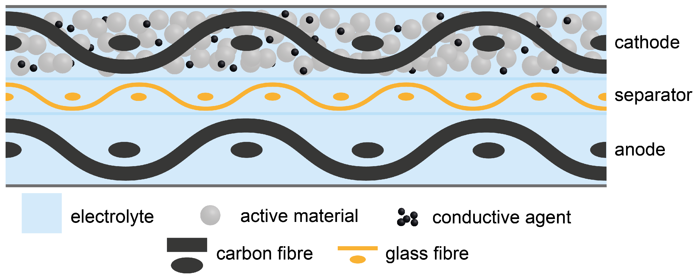
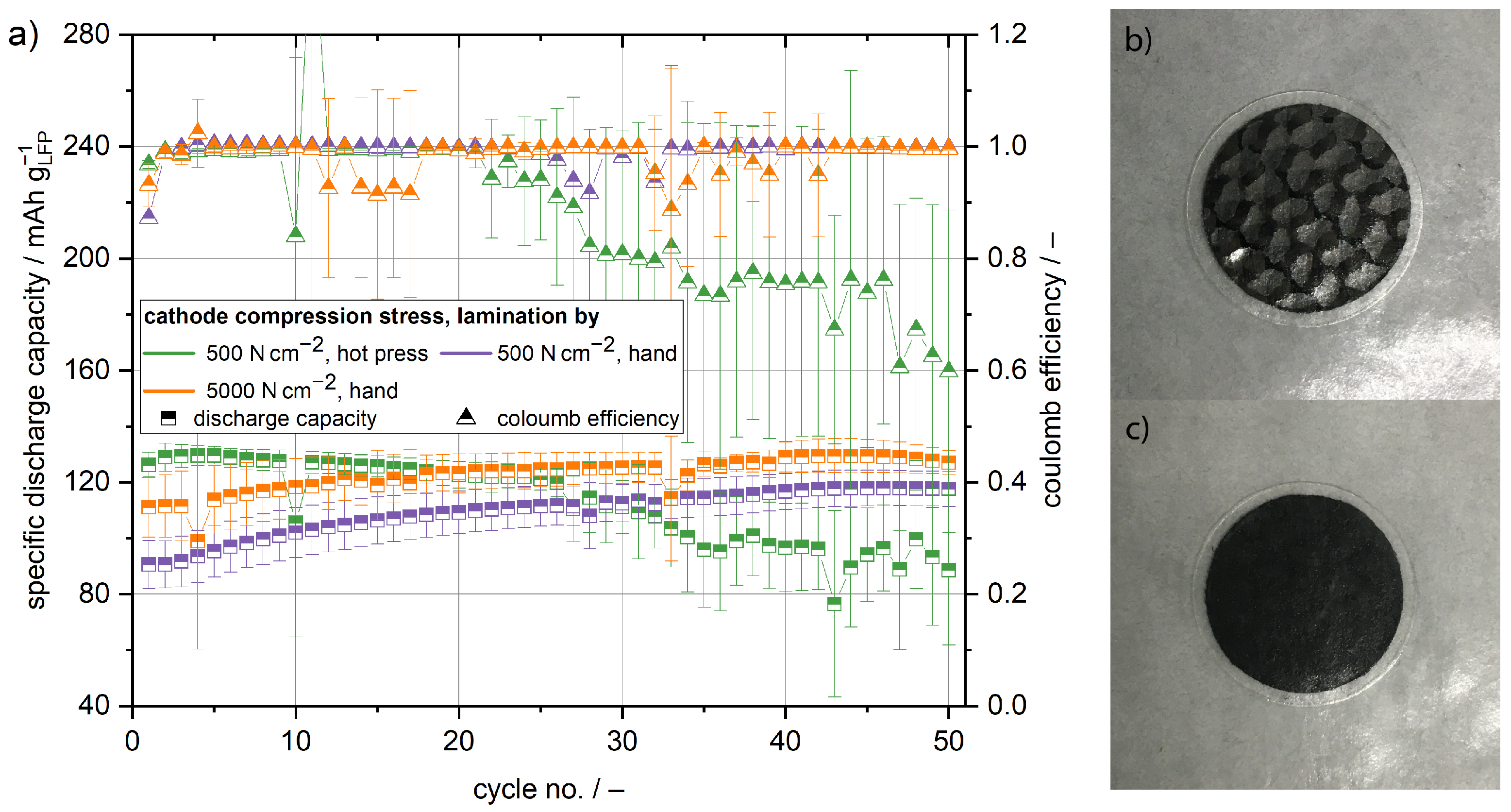
Section 2.2 cathode half cells have been built using a polymer film separator and lithium metal anode, to evaluate the electrochemical performance of the structural cathodes. The specific discharge capacity of the cathode half cells is presented in Figure 2. Lamination and compression pressure directly influence the cycling capacity of the cathode half cells. Comparing the initial cycle of the manually laminated cells, the cathodes compressed with 5000 N cm 2 exhibit higher capacities than the cathodes compressed at 500 N cm 2 ( 113 mAh g LFP 1 compared to 91 mAh g LFP 1 ). With the increasing cycle number the capacity of both cathodes increases. After 50 cycles, a capacity of 125 mAh g LFP 1 and 118 mAh g LFP 1 was reached for the cathode compressed at 5000 N cm 2 and 500 N cm 2 , respectively. The increasing capacity is most probably a result of better active material utilisation due to the improved contact of the cathode and the polymer film separator. From 
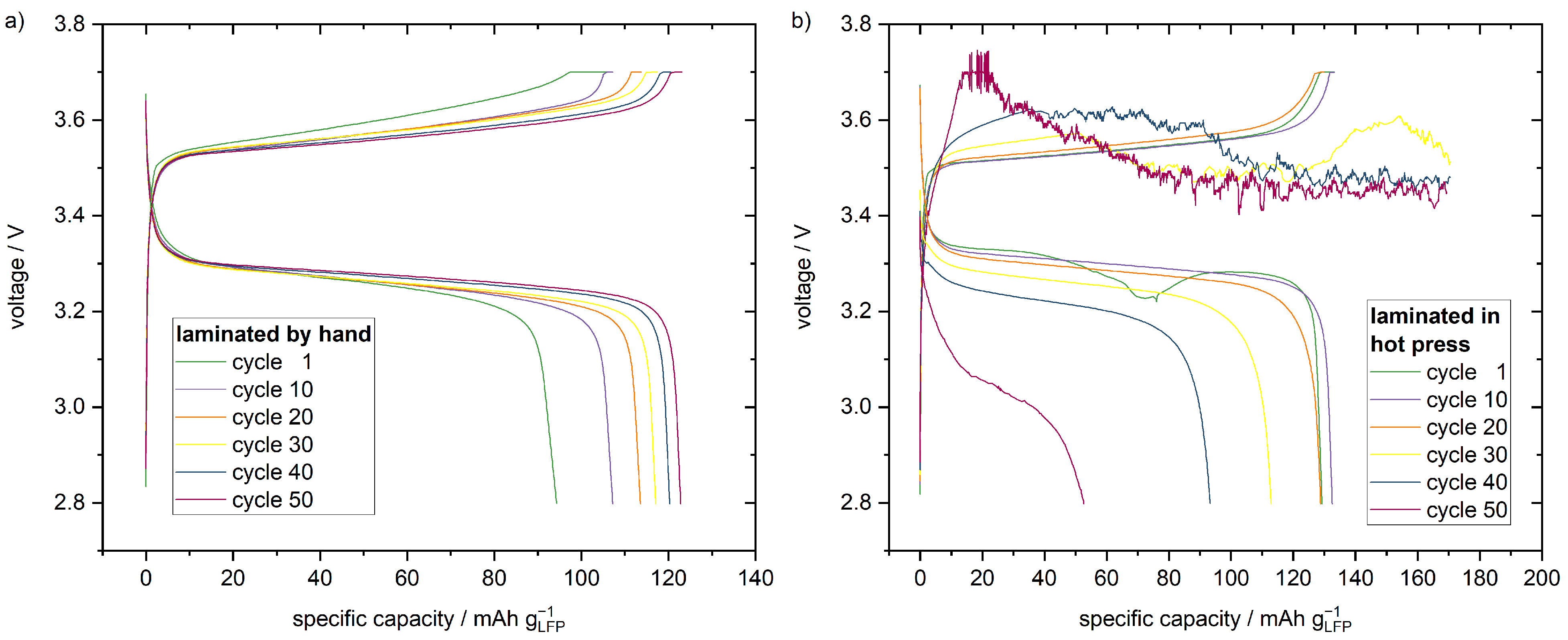
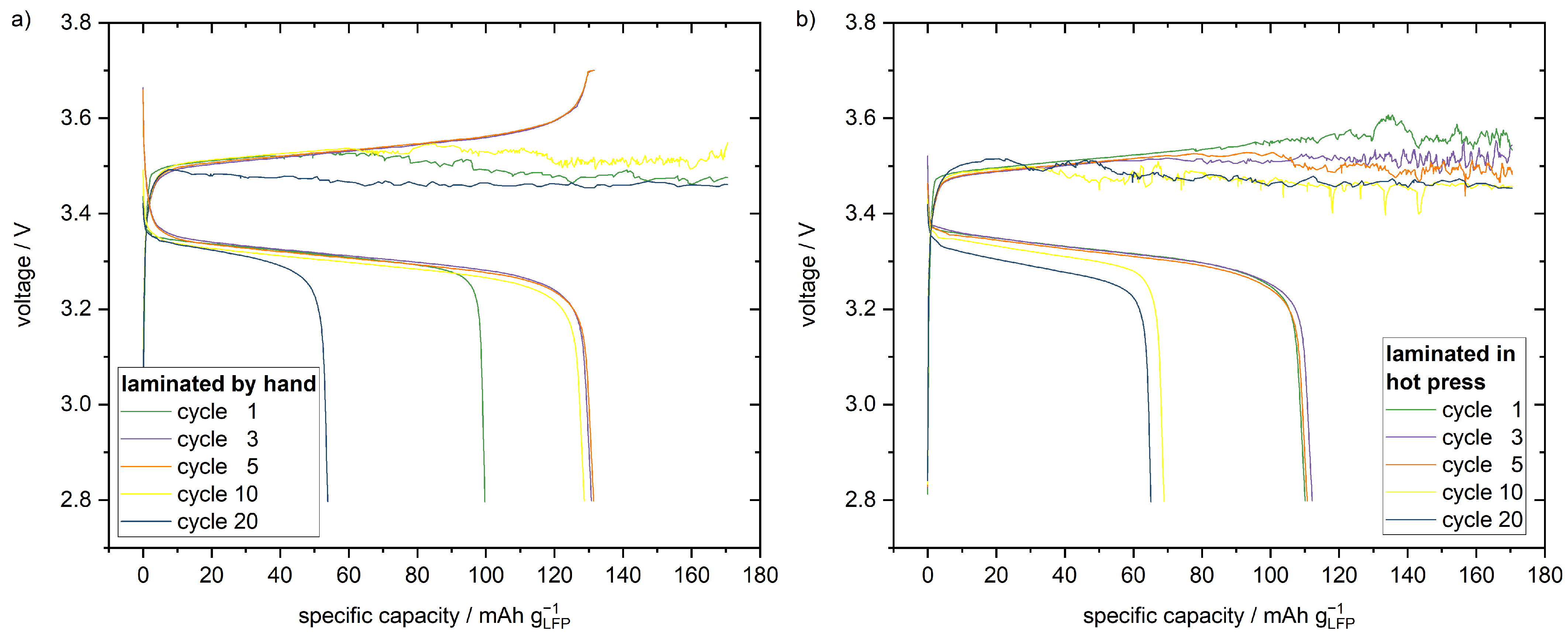
Figure 2b,c, it is obvious that the manual lamination results in insufficient contact between the structural cathode and the polymer film separator. The regions of insufficient contact are visible as brighter spots. Due to the pressure in the coin cell housing and the cyclisation temperature of 80 °C, the contact between the structural cathode and polymer film separator improves over time. This is seconded by the voltage profiles of different cycles shown in Figure 3. The specific charge that is extracted at the plateau voltage of around 3.3 V during discharge increases with the increasing cycle number and, therefore, the active material utilisation increases, as well. Furthermore, the plateau voltage during charging slightly decreases and increases during discharging with increasing cycle number. This is another indicator for a reduction of the cell resistance, due to the improved contact between cathode and separator.
In order to achieve better initial active material utilisation, cells were produced by using a hot press to laminate the electrodes and separator. In Figure 2c, no brighter spots are visible, indicating proper contact between the cathode and the separator. This is supported by the polarisation of the cells during cycling. At a state of charge equalling to 20 mAh g LFP 1   , the cells laminated in the hot press exhibit a cell polarisation of 210 mV in the first cycle, which is smaller compared to the 300 mV polarisation of the manually laminated cells, as shown in Figure 3. Therefore, the inner resistance of the cells laminated in the hot press is smaller. It is reasonable to assume the decrease in cell resistance is a result of better interface contact after hot pressing in comparison to manual lamination. Due to the initially better interface contact, the cells laminated in the hot press exhibit with 126 mAh g LFP 1 the highest capacity in the first cycle. However, in contrast to the manually laminated cells, the capacity fades with increasing cycle number, but during the first 25 cycles only slightly. This observed small capacity fading is in good agreement with previous studies researching solid state batteries with LFP as a cathode active material and a PEO based polymer electrolyte [25,26,27]. In the later cycles, much more pronounced capacity fading occurs. In general, the coulomb efficiency is well above 99% during the first 20 cycles, but subsequently decreases rapidly. Until cycle 50, the coulomb efficiency drops to around 60%. The accelerated decrease of the capacity and the coulomb efficiency can not be explained by the usual degradation of the material system. A likely explanation for the faster degradation are micro short circuits over the separator due to lithium dendrite growth. The voltage profile reveals that the cells do not reach their cutoff potential in the region of rapid capacity fading and most probably, the current is conducted over the separator. This explanation is in accordance with to Homann et al. [28], who reported noisy voltages during the galvanostatic cycling of LFP-based cathodes with a PEO-based separator. In the case of the structural cathodes, the lamination process plays a critical role for this behaviour. During the lamination in the hot press, higher pressure is applied to the cathode compared to the lamination by hand. Because of the inhomogeneous thickness of woven carbon textiles, the separator is locally subject to even higher pressure during the lamination in the hot press, which results in weak points vulnerable to dendrite growth and short circuits.
The cathodes were further cycled with a structural separator, which is a glass fibre textile that is impregnated with a electrolyte composed of PEO and LiTFSI. The mass fraction of the glass fibres in the structural separator is found to be approximately 17 wt . % . Therefore, the fibre volume content is 10% and, thus, much lower than in the cathode. The reduced fibre volume content corresponds to a lower amount of filler material in the separator and ensures good ionic conductivity, which significantly decreases with the increasing volume of non-conducting phases [29]. The structural separator has a thickness of approximately 90 μ m , which is slightly thinner than the polymer film separator. Measured by electrochemical impedance spectroscopy (EIS) at a temperature of 80 °C, the structural and polymer film separator exhibit comparable ionic conductivities of 0.46 mS cm 1 and 0.44 mS cm 1 
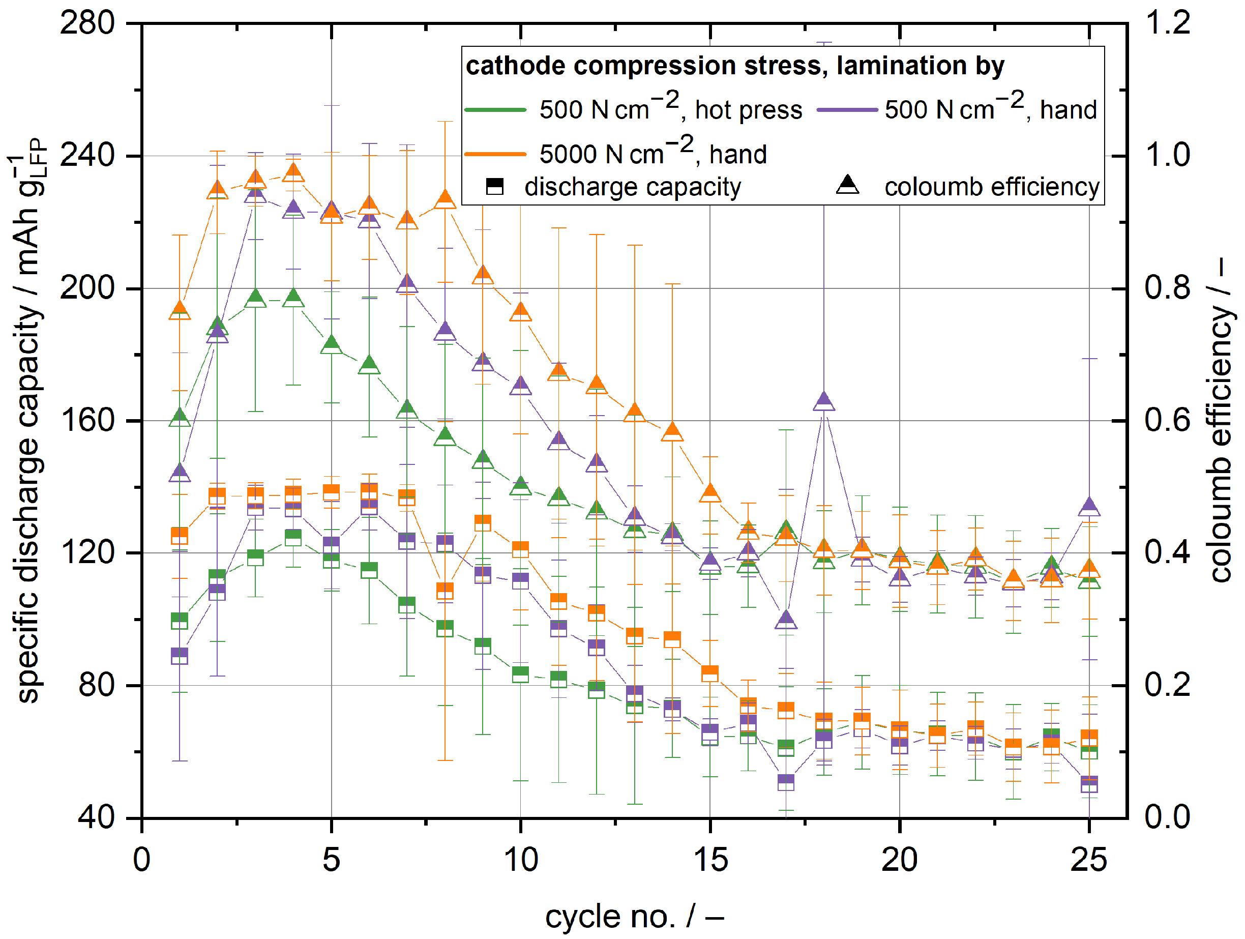
, respectively. Nevertheless, the cycling behaviour of the cathode half cells with the structural separator is found to be very different compared to cells with the polymer film separator. The cells with the cathode and separator compressed at a higher pressure achieve capacities of maximum 139 mAh g LFP 1 and, therefore, the best capacities of all investigated cells, see 
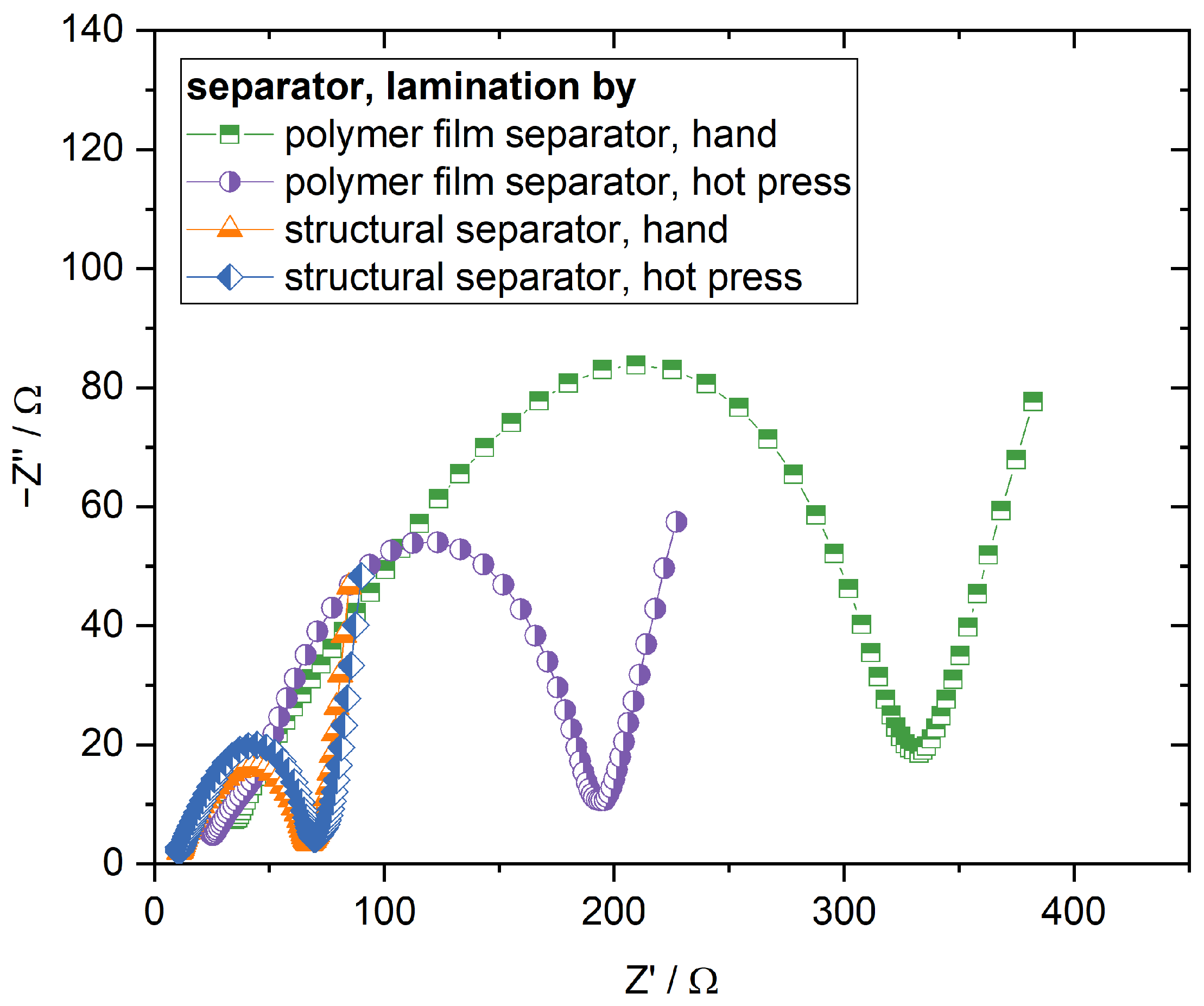
Figure 4. Because the ionic conductivity of the structural and polymer film separator are similar, the higher initial capacity in comparison to the cells with the polymer film separator can be mainly accounted for better contact between structural separator and cathode and the slightly lesser thickness of the structural separator. The discharge capacity of the manually laminated cells approaches its maximum after the first or second cycle, respectively, and remains stable for a few cycles thereafter. If one also takes into account that the maximum capacity is higher in comparison to the cells with the polymer film separator laminated in the hot press, it becomes clear that manual lamination leads to sufficient contact between the structural cathode and separator. This is verified by the EIS measurements of the cathode half cells shown in Figure 5. While there is a significant difference in cell impedance for the cells with the polymer film separator between the manual lamination and lamination in the hot press, there is no meaningful difference when the cells with the structural separator are compared against each other. The impedance of the different cells with the structural separator is smaller than the impedance of the cells with the polymer film separator laminated in the hot press, further supporting that better interface contact is the main reason for the observed higher capacities. Moreover, the polarisation of the manually laminated cells with the structural separator at a state of charge equalling to 20 mAh g LFP 1 is with 200 mV smaller than the polarisation of the cells with the polymer film separator laminated in the hot press, as well. The comparison of the different lamination techniques shows again that lamination in the hot press does not have any beneficial influence in comparison to the cells with the polymer film separator. While the cell polarisation slightly decreases to 170 mV, the initial capacity is even worse compared to the manually laminated cells. Unlike for the cells with the polymer film separator, it is evident that the capacity already degrades after a few cycles significantly, independent of the lamination process. The pronounced capacity fading is accompanied by a decrease in coulomb efficiency. After 15 cycles, no coulomb efficiency higher than 50% was observed. The decrease in capacity and coulomb efficiency can be explained by micro short circuits caused by lithium dendrite growth similar to the polymer film separator [28]. It can be concluded that the structural separator does not withstand lithium dendrite growth as well as the polymer film separator, because the degradation happens much faster and is more pronounced. This is supported by a maximum coulomb efficiency of only 97% observed for the manually laminated cells, which is relatively poor for this type of system [26,30]. The coulomb efficiency of the hot press-laminated cells does not reach any values above 78%. This indicates that the structural separator is like the polymer film separator locally weakened by the lamination in the hot press, because of the inhomogeneous pressure distribution due to the inhomogeneous thickness of the fibre textiles. Therefore, micro short circuits as a result of lithium dendrite growth occur even faster in the cells laminated in the hot press. This is supported by the voltage profiles depicted in Figure 6. The manually laminated cells reach the cut-off voltage for the charging step in the first cycles, but during the successive cycles the voltage becomes noisy in the charging step. Similar to the cathode half cells with the polymer film separator, which have been laminated in the hot press, the voltage noise is accompanied by a degradation of the discharge capacity. The cells that have been laminated in the hot press never reach the cut-off voltage in the charging step and exhibit even faster capacity degradation.

3.2. Anode Half Cells

In order to assess the specific capacity of the carbon fibre anode, half cells have been built. The fibre mass fraction of the structural anode is approximately 62 wt . % . This is equivalent to a fibre volume content of 67%. From 
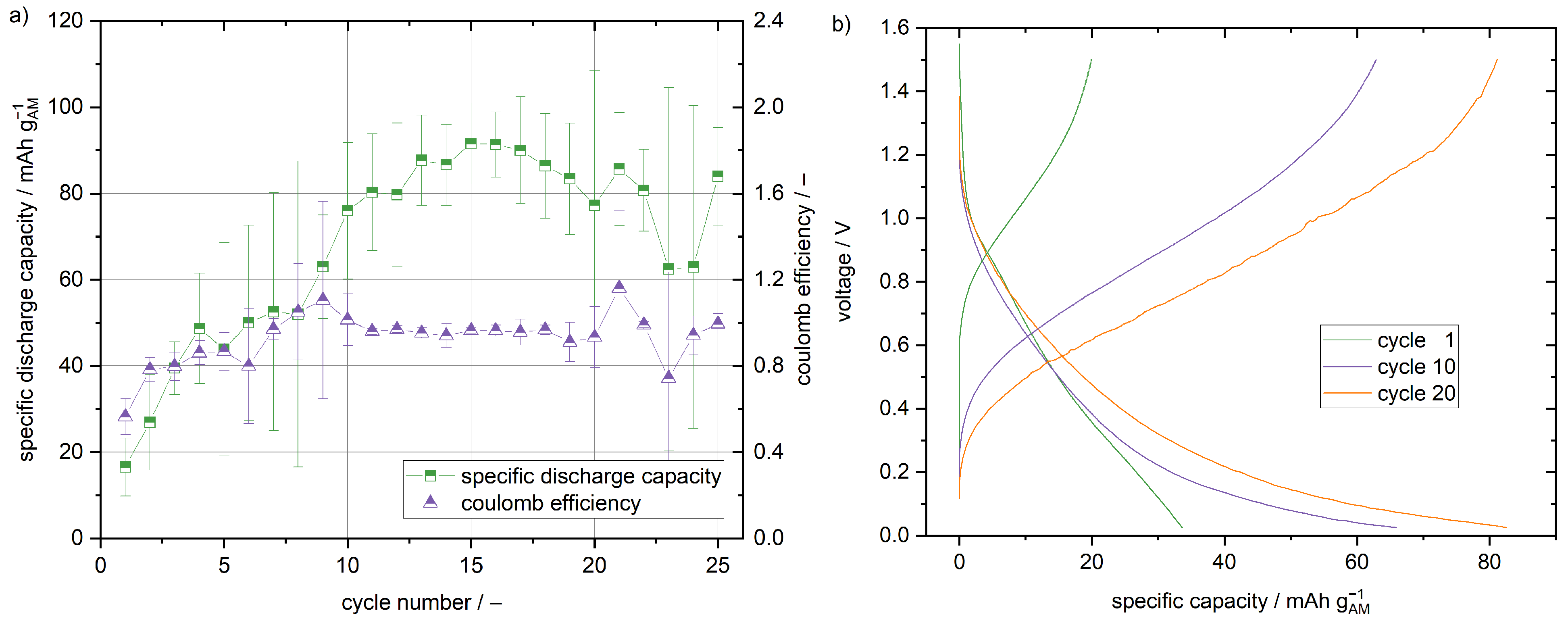
Figure 7, it is evident that the capacity changes significantly with the cycle number. During the first fifteen cycles, the capacity increases from 17 mAh g AM 1 to 92 mAh g AM 1 . During further cycling, the capacity decreases again. The anode half cells have been laminated in the hot press. Therefore, the increasing capacity is not related to an improvement of the interface contact, but must be explained by structural changes of the carbon fibres and, thus, the structural anode. In accordance to Snyder et al. [10] the formation of small fractures during the cycling is suspected to be the reason for the increasing capacity. Small fractures result in the partial exfoliation of some graphene sheets and locally damaged sizing of the carbon fibres. Both make the carbon fibres more accessible for the intercalation of lithium ions. With 92 mAh g AM 1 , the maximum discharge capacity is quite poor compared to the cycling data of carbon fibres found in the literature, especially considering the rate of 0.01C with respect to the 372 mAh g AM 1 capacity of graphite [10,31,32,33,
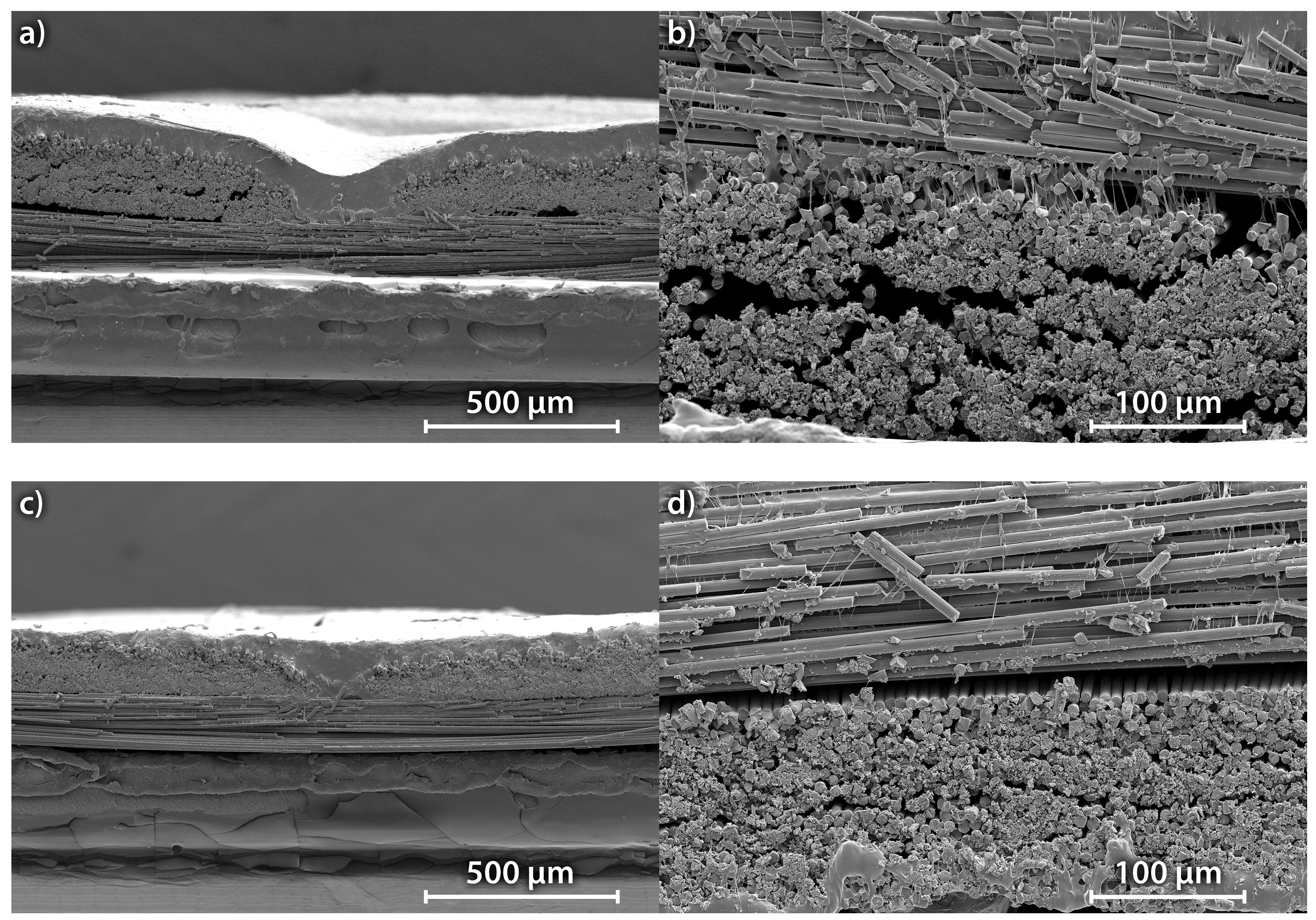
34]. No further anode half cell tests with the structural separator have been conducted, because significant problems with lithium dendrite formation were observed in the cathode half cell tests. In contrast to the findings known in literature, the carbon fibres were coated with an all-solid-state electrolyte. The wetting of the carbon fibres with an all-solid-state electrolyte seems to be insufficient compared to an electrolyte with liquid components. The cross section of a structural anode is depicted in Figure 8. The electrolyte is visible as small white filaments connecting the carbon fibres. It is obvious that the wetting of the carbon fibres is insufficient, because the electrolyte covers only a small fraction of the carbon fibre surface. A large part of the electrolyte is located on top of the carbon fibre weave, especially before compression in the hot press. The compression reduces the roughness of the surface, but does not improve the wetting of the carbon fibres. Even after compression, big pores can be detected in the scanning electron microscope (SEM) images. Therefore, the accessibility of the available carbon is worse compared to the usage of a liquid electrolyte, which perfectly wets all the carbon fibres. Serious improvements of the distribution of the solid electrolyte in the carbon fibres are necessary to make a viable carbon fibre-based all-solid state anode.
The small coulomb efficiency of 56% in the first cycle reveals that a significant amount of lithium ions is irreversibly lost. Previous studies have revealed that even with the liquid electrolyte, significant amounts of lithium are irreversibly trapped in the carbon fibres [31,32,33]. It is reasonable to assume that the lithium diffuses into the deeper layers of the carbon fibres and cannot be accessed anymore upon discharge. This is a major issue in this study, because of the poor wetting of the structural anodes with the solid electrolyte. The carbon fibres are only partially in contact with the electrolyte and are, therefore, only partially lithiated during charging. The partial lithiation results in a concentration gradient of lithium within the fibres and, therefore, in the diffusion of lithium within the fibres. Improving the wetting of the carbon fibres with the solid electrolyte is crucial to improve the capacity and coulomb efficiency of structural anodes. As lithium is trapped too, when a liquid electrolyte is used, further prelithiation of the carbon fibres might be necessary to reduce initial lithium losses and achieve sufficient capacities in the future. With the increasing cycle number, the coulomb efficiency increases as more of the theoretical capacity of the carbon fibres can be accessed. From Figure 7, it is evident that the overpotentials decrease and the plateau region increases with the increasing cycle number. During the first charge cycle (intercalation of lithium into the carbon fibre), a small second plateau region around 0.8 V is visible. This vanishes in the consecutive cycles and, thus, is a result of irreversible processes contributing to the poor coulomb efficiency, especially in the first cycle.

3.3. Full Cells

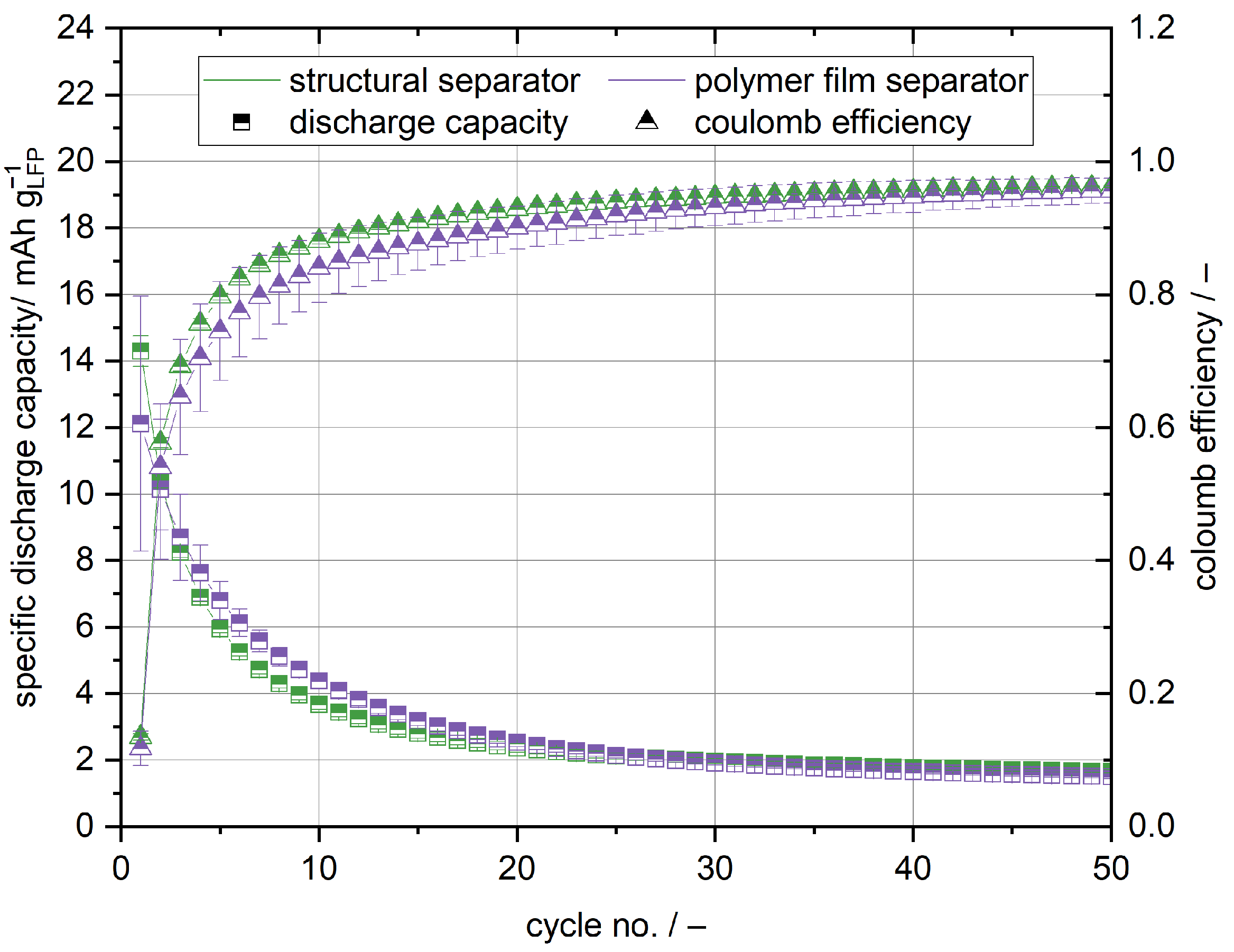
The cells with the structural cathode and anode exhibit no significant capacity regardless of the used separator, as shown in Figure 9. The highest capacity of 14 mAh g LFP 1 can be accessed in the initial cycle. In the later cycles, the capacity significantly drops to below 2 mAh g LFP 1 . Similarly to the anode half cells, the coulomb efficiency is very low in the initial cycle, but increases to over 95% after 50 cycles. The general trend of capacity and coulomb efficiency is in accordance with the cycling data of the anode half cells. Especially in the first cycles, lithium is trapped in carbon fibres and is lost due to irreversible side reactions [31,32,33]. However, in contrast to the half cell setup, only the lithium in the active material is available for the energy storage and conversion, so that the lithium supply is limited. Lithium depletes and the capacity decreases with increasing cycle number.
On the contrary to the cathode half cell setup, no decrease of the coulomb efficiency with cycle life is apparent even though the cell stacks have been laminated in the hot press and regardless of the used separator. This supports the hypothesis that in the cathode half cell setup lithium dendrite growth is responsible for capacity fading and the decrease of the coulomb efficiency. Lithium dendrites are much less of an issue in the full cell setup, as no lithium metal anode is used [35].
In summary, the anode is the bottle neck of this structural battery setup. In order to increase the capacity, it is necessary to prevent the high initial lithium losses and, therefore, to increase the lithium availability. To cope with this issue, the wetting of the carbon fibres in the structural anode needs to be improved to reduce the diffusion of lithium into non-contacted areas of the carbon fibre due to concentration gradients arising from inhomogeneous lithiation, as shown in Section 3.2. However, since initial lithium losses can even be observed with liquid electrolyte, which perfectly wets the carbon fibres, prelithiation of the carbon fibres might additionally be necessary to increase the lithium availability. This issue needs to be addressed in further research.

3.4. Structural Battery Demonstrator

In addition to the previously described coin cells, a structural battery in the pouch cell format (cathode: 5   cm × 5   cm , separator: 6.5   cm × 6.5   cm , anode: 5.5   cm × 5.5   cm 
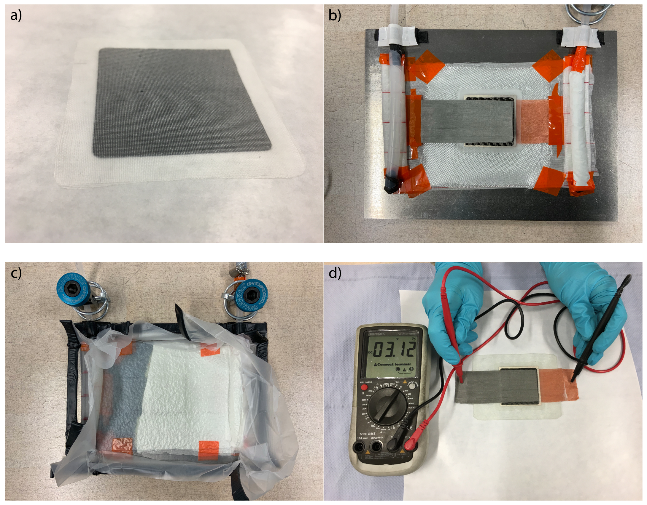
) was built. For the structural battery demonstrator, a lithium metal anode was used, because, as discussed before, lithium depletion is an issue when using the presented structural carbon fibre anode. The preparation of the demonstrator is shown in Figure 10. All constituents were dried for at least 4 h at 40 °C in a vacuum climate chamber before use. All work was conducted in a dry room with a dew point better than −40 °C. Structural cathode, structural separator, and lithium metal have been laminated in a hot press applying a pressure of 100 N cm 2 at 80 °C. The lay up for the composite integration was prepared on a metal plate coated with chemlease 255 release agent. The laminated cell stack was sandwiched between four sheets of Interglas 91111 glass fibre. A nickel mesh was used as current collector for the cathode and a copper mesh was used for the anode. Additional layers of peel ply and fleece have been used, to ensure a good vacuum and homogeneous epoxy infiltration. On two opposing sides, spiral tubes were fixated, one for the connection to the vacuum pump and one for the supply of epoxy resin. The whole set up was sealed airtight with vacuum bagging film and sealing tape. After the evacuation of residual air, the set up was infiltrated with epoxy resin L and the hardener EPH 161 in a 100:25 mixture by weight. After 24 h curing at 20 °C, the structural battery was demolded.
Initially, the same cycling protocol as for the cathode half cells and full cells was tested for the demonstrator. Because of the very high overpotentials, the demonstrator could not be charged, as the charging step was instantly terminated in Section 2.5, by the described voltage and current criteria. Therefore, the potential window for the cycling procedure had to be increased. The cutoff voltage for charging was increased to 4 V and the cut off voltage for discharging was decreased to 2.5 V. Furthermore, the charge and discharge rate were reduced to 0.02C in an effort to cope with the high overpotentials and the dendrite growth observed during the cycling of the cathode half cells with the structural separator. From 
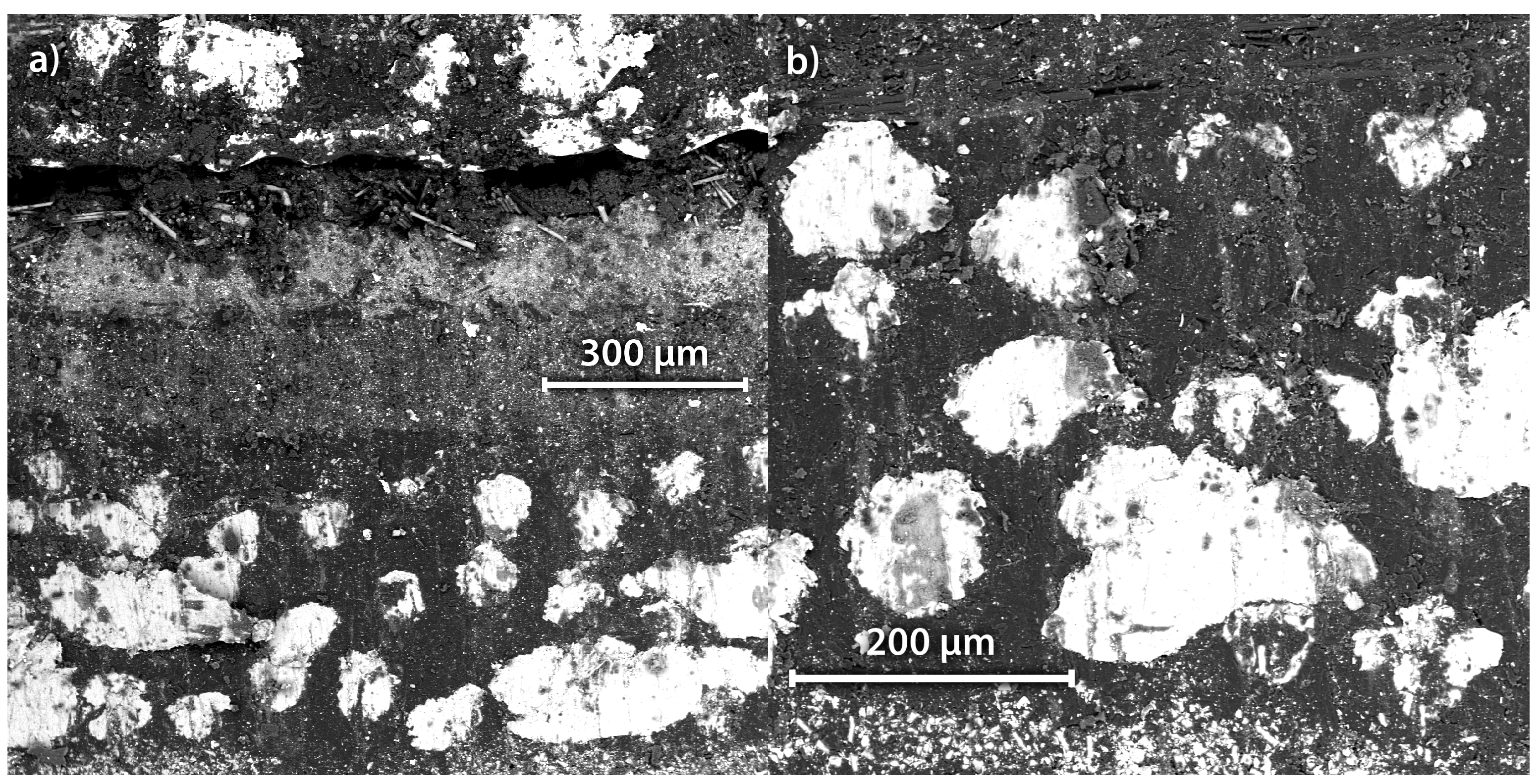
Figure 11, it is obvious that the cell voltage nearly instantly reaches the cut off voltage of 4 V during the charge and decreases to approximately 2.9 V during discharge. For comparison with the corresponding cathode half cell setup, the voltage plateaus were found to be around 3.5 V for the charge and 3.3 V for discharge. A likely reason for the observed overpotentials is found in the infiltration procedure with the epoxy resin. It cannot be ruled out that epoxy resin leaked in between some of the functional components, although the electrodes and separator have been laminated before the infiltration. A higher inner resistance and, therefore, overpotential would be the logical consequence. As the metal meshes used as a current collector were only mechanically connected to the electrodes due to the vacuum applied during infiltration, it is highly reasonable that epoxy resin partially isolated both from each other. To further investigate this issue, the demonstrator was cut under ambient atmosphere with a scroll saw and SEM pictures of the cut were taken. In Figure 12, the different functional layers of the structural battery demonstrator can be clearly identified. The visible layers are from top to bottom: the copper mesh current collector, a fracture as a consequence of the degradation of the lithium metal anode during the cutting under ambient atmosphere, the structural separator, the structural cathode, and the nickel mesh current collector. It is clearly visible that epoxy resin is partially isolating the strands of the metal mesh current collectors from each other. It is suspected that the connection of the metal mesh current collectors can be optimised by the use of an electrical conducting silver glue.
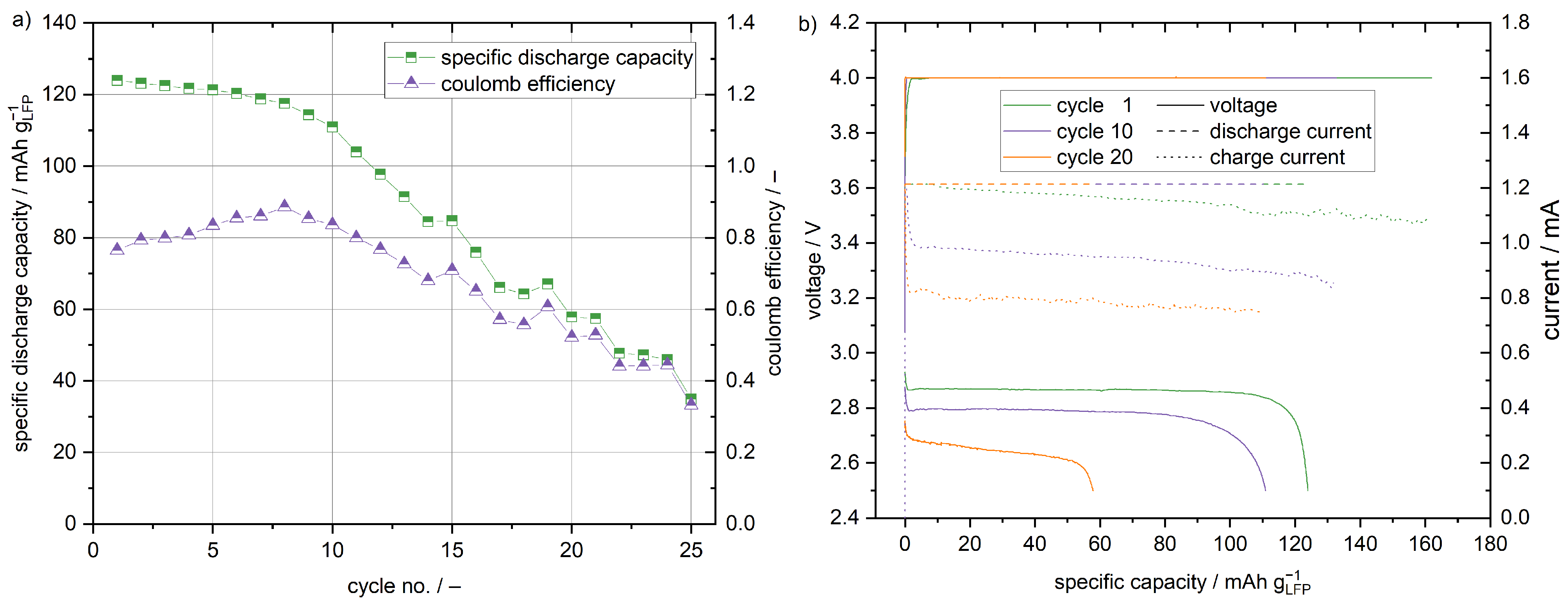
As shown in Figure 11, the maximum specific capacity of 124 mAh g LFP 1 is reached in the first cycle. Considering the weight of the electrodes and the separator, a maximum specific energy of 64 Wh kg 1 is achieved. The metal mesh current tab, surrounding the glass fibres and epoxy resin, have been neglected in this calculation. Similar to the cathode, half cells with a glass fibre separator capacity fading occurs. After 10 cycles, the capacity decreased to 111 mAh g LFP 1 . Much more pronounced is the capacity fading visible for the later cycles. The coulomb efficiency reaches no value higher than 89%. In accordance with the cathode half cells with the glass fibre separator, dendrite growth is the suspected reason for poor coulomb efficiency and pronounced capacity fading. The current profiles in Figure 11 support that micro short circuits occur in the structural battery demonstrator, as well. Since the charging is reduced to the constant voltage step due to the high overpotentials, the characteristic noise is visible in the current during charging and not the voltage. Moreover, it is obvious that the resistance of the structural battery demonstrator increases with the cycle life as the current decreases. Most likely different polarisation processes such as concentration-, activation- and interface-polarisation contribute to the increase in cell resistance. To quantify the contribution of the different processes, in-depth EIS and distribution of relaxation times (DRT) analyses would be necessary, but this is beyond the scope of this study. The current decreases with cycle life, but, because of the micro short circuits, it is never below 50% of its nominal value, which is one the cutoff criteria of the charging step; therefore, the charging step is always terminated by the time criterion described in Section 2.5. As a result, the absolute charge capacity decreases with the decreasing current. To overcome the issue of dendrite formation, it is necessary to improve the mechanical properties of the solid state electrolyte [35]. For the current system, a reduction of the cyclisation temperature could improve the mechanical properties. The mechanical properties of polymers are strongly dependant on the temperature [36]. In general, it is desirable to reduce the temperature requirements of the structural battery composites to enable a less restricted use. However, in contrast to the mechanical properties, the ionic conductivity of a polymer electrolyte decreases with decreasing temperature [37]. To date, there is no all-solid-state electrolyte that fully satisfies the requirements of structural battery composites with respect to the mechanical properties, ionic conductivity, stability, and processability. Once new polymer electrolyte generations become available, the described fabrication processes can be easily adapted to greatly enhance the properties of the proposed structural battery composites.

4. Conclusions

Various configurations of half and full cells with structural electrodes and separator have been cycled. With 139 mAh g LFP 1 , the half cells with the structural cathode and structural separator reach the highest capacities, but exhibit rapid capacity fading due to the lithium dendrite growth. Depending on the utilised separator, the lamination of the electrodes and separator has a crucial influence on the cycling performance. Using the polymer film separator, lamination in a hot press can significantly improve the interface contact and, therefore, decrease cell impedance and the observed polarisation, and increase the initial capacity of the cells. For the all-solid-state carbon fibre anode, the wetting of the carbon fibres with the electrolyte is found to be crucial. In the current study, the electrolyte was largely present at the surface, but not within the carbon fibre textile. The insufficient wetting contributes to high irreversible lithium losses during cycling. Because of these losses, cells with the structural anode and cathode are deplete of lithium and only show capacities lower than 14 mAh g LFP 1 . However, using a lithium foil-based anode, a structural battery demonstrator reaching 124 mAh g LFP 1 has been presented. With respect to the electrodes and the separator, this is equivalent to a specific energy of 64 Wh kg 1 . For the future application of structural batteries utilising only all-solid-state battery components, it is especially necessary to improve the distribution of the electrolyte and cathode materials within the carbon fibre textiles and to improve the interface of the cell stack. While this work focused on production processes and the electrochemical properties of structural battery composites, the mechanical properties of this material class are equally important and need to be addressed in future research. Especially the mechanical as well as the electrochemical properties of the utilised all-solid-state electrolyte are crucial and need to be optimised to build viable structural battery composites that can be operated at an ambient temperature. Once new electrolyte generations become available, the presented processes can be easily adapted. Furthermore, the electrochemical performance under load-bearing conditions and the influence of the electrochemical cycling on the mechanical properties need to be addressed in future research.

Author Contributions

Conceptualisation, D.V., P.M. and A.K.; methodology, D.V.; software, D.V.; validation, D.V., P.M. and A.K.; formal analysis, D.V.; investigation, D.V.; resources, A.K.; data curation, D.V.; writing—original draft preparation, D.V.; writing—review and editing, D.V., P.M. and A.K.; visualisation, D.V.; supervision, P.M. and A.K.; project administration, A.K.; funding acquisition, A.K. All authors have read and agreed to the published version of the manuscript.

Funding

We would like to acknowledge the funding by the Deutsche Forschungsgemeinschaft (DFG, German Research Foundation) under Germany’s Excellence Strategy—EXC 2163/1—Sustainable and Energy Efficient Aviation—Project-ID 390881007, the financial support of the project Mobilise (grant number ZN3247) by the Ministry for Science and Culture of the State of Lower Saxony (MWK). Moreover, the first steps of this work were supported (support code 50RP1720) by the Federal Ministry for Economic Affairs and Energy on the basis of a decision by the German Bundestag. The authors would like to also thank the INNOspace Masters DLR challenge.

Acknowledgments

Moreover, we would like to thank our colleagues Mozaffar Abdollahifar, Heather Cavers, Julian Mayer, Milena Perović, and Dominik Steckermeier for our fruitful discussions.

Conflicts of Interest

The authors declare no conflict of interest.

Abbreviations

The following abbreviations are used in this manuscript:
AMActive material
DRTDistribution of relaxation times
EISElectrochemical impedance spectroscopy
LFPLithium iron phosphate
LiTFSILithium bis(trifluoromethanesulfonyl)imide
PEOPolyethylene oxide
PBTPolybutylene terephthalate
SEMScanning electron microscope

References

  1. Flightpath 2050: Europe’s Vision for Aviation; Maintaining Global Leadership and Serving Society’s Needs; report of the High-Level Group on Aviation Research; Policy/European Commission, Publ. Off. of the Europ. Union: Luxembourg, 2011.
  2. Bills, A.; Sripad, S.; Fredericks, W.L.; Singh, M.; Viswanathan, V. Performance Metrics Required of Next-Generation Batteries to Electrify Commercial Aircraft. ACS Energy Lett. 2020, 5, 663–668. [Google Scholar] [CrossRef]
  3. Löbberding, H.; Wessel, S.; Offermanns, C.; Kehrer, M.; Rother, J.; Heimes, H.; Kampker, A. From Cell to Battery System in BEVs: Analysis of System Packing Efficiency and Cell Types. World Electr. Veh. J. 2020, 11, 77. [Google Scholar] [CrossRef]
  4. Snyder, J.F.; Gienger, E.B.; Wetzel, E.D. Performance metrics for structural composites with electrochemical multifunctionality. J. Compos. Mater. 2015, 49, 1835–1848. [Google Scholar] [CrossRef]
  5. Thomas, J.P.; Qidwai, M.A. Mechanical design and performance of composite multifunctional materials. Acta Mater. 2004, 52, 2155–2164. [Google Scholar] [CrossRef]
  6. Wong, E.L.; Baechle, D.M.; Xu, K.; Carter, R.H.; Snyder, J.F.; Wetzel, E.D. Design and Processing of Structural Composite Batteries. In Proceedings of the Society for the Advancement of Materiel and Process Engineering (SAMPE) 2007 Symposium and Exhibition, Baltimore, MD, USA, 3–7 June 2007. [Google Scholar]
  7. Wetzel, E.D. Reducing Weight: Multifunctional Composites Integrate Power, Communications, and Structure. AMPTIAC Q. 2004, 8, 91–95. [Google Scholar]
  8. Snyder, J.F.; Carter, R.H.; Wong, E.L.; Nguyen, P.A.; Xu, K.; Ngo, E.H.; Wetzel, E.D. Multifunctional Structural Composite Batteries. In Proceedings of the Society for the Advancement of Materiel and Process Engineering (SAMPE) 2006 Fall Technical Conference, Dallas, TX, USA, 6–9 November 2006. [Google Scholar]
  9. Snyder, J.F.; Carter, R.H.; Wetzel, E.D. Electrochemical and Mechanical Behavior in Mechanically Robust Solid Polymer Electrolytes for Use in Multifunctional Structural Batteries. Chem. Mater. 2007, 19, 3793–3801. [Google Scholar] [CrossRef]
  10. Snyder, J.F.; Wong, E.L.; Hubbard, C.W. Evaluation of Commercially Available Carbon Fibers, Fabrics, and Papers for Potential Use in Multifunctional Energy Storage Applications. J. Electrochem. Soc. 2009, 156, A215. [Google Scholar] [CrossRef]
  11. Ekstedt, S.; Wysocki, M.; Asp, L.E. Structural batteries made from fibre reinforced composites. Plast. Rubber Compos. 2010, 39, 148–150. [Google Scholar] [CrossRef]
  12. Moyer, K.; Boucherbil, N.A.; Zohair, M.; Eaves-Rathert, J.; Pint, C.L. Polymer reinforced carbon fiber interfaces for high energy density structural lithium-ion batteries. Sustain. Energy Fuels 2020, 4, 2661–2668. [Google Scholar] [CrossRef]
  13. Moyer, K.; Meng, C.; Marshall, B.; Assal, O.; Eaves, J.; Perez, D.; Karkkainen, R.; Roberson, L.; Pint, C.L. Carbon fiber reinforced structural lithium-ion battery composite: Multifunctional power integration for CubeSats. Energy Storage Mater. 2020, 24, 676–681. [Google Scholar] [CrossRef]
  14. Asp, L.E.; Bouton, K.; Carlstedt, D.; Duan, S.; Harnden, R.; Johannisson, W.; Johansen, M.; Johansson, M.K.G.; Lindbergh, G.; Liu, F.; et al. A Structural Battery and its Multifunctional Performance. Adv. Energy Sustain. Res. 2021, 2, 2000093. [Google Scholar] [CrossRef]
  15. Ihrner, N.; Johannisson, W.; Sieland, F.; Zenkert, D.; Johansson, M. Structural lithium ion battery electrolytes via reaction induced phase-separation. J. Mater. Chem. A 2017, 5, 25652–25659. [Google Scholar] [CrossRef]
  16. Schneider, L.M.; Ihrner, N.; Zenkert, D.; Johansson, M. Bicontinuous Electrolytes via Thermally Initiated Polymerization for Structural Lithium Ion Batteries. ACS Appl. Energy Mater. 2019, 2, 4362–4369. [Google Scholar] [CrossRef]
  17. Zhao, C.D.; Guo, J.Z.; Gu, Z.Y.; Wang, X.T.; Zhao, X.X.; Li, W.H.; Yu, H.Y.; Wu, X.L. Flexible quasi-solid-state sodium-ion full battery with ultralong cycle life, high energy density and high-rate capability. Nano Res. 2022, 15, 925–932. [Google Scholar] [CrossRef]
  18. Li, H.; Zhang, X.; Zhao, Z.; Hu, Z.; Liu, X.; Yu, G. Flexible sodium-ion based energy storage devices: Recent progress and challenges. Energy Storage Mater. 2020, 26, 83–104. [Google Scholar] [CrossRef]
  19. Harnden, R.; Peuvot, K.; Zenkert, D.; Lindbergh, G. Multifunctional Performance of Sodiated Carbon Fibers. J. Electrochem. Soc. 2018, 165, B616–B622. [Google Scholar] [CrossRef]
  20. Harnden, R.; Zenkert, D.; Lindbergh, G. Potassium-insertion in polyacrylonitrile-based carbon fibres for multifunctional energy storage, morphing, and strain-sensing. Carbon 2021, 171, 671–680. [Google Scholar] [CrossRef]
  21. Danzi, F.; Camanho, P.P.; Braga, M.H. An All-Solid-State Coaxial Structural Battery Using Sodium-Based Electrolyte. Molecules 2021, 26, 5226. [Google Scholar] [CrossRef]
  22. Ransil, A.; Belcher, A.M. Structural ceramic batteries using an earth-abundant inorganic waterglass binder. Nat. Commun. 2021, 12, 6494. [Google Scholar] [CrossRef]
  23. Wiegmann, E.; Helmers, L.; Michalowski, P.; Kwade, A. Highly scalable and solvent-free fabrication of a solid polymer electrolyte separator via film casting technology. Adv. Ind. Manuf. Eng. 2021, 3, 100065. [Google Scholar] [CrossRef]
  24. Macdonald, J.R. Impedance spectroscopy. Ann. Biomed. Eng. 1992, 20, 289–305. [Google Scholar] [CrossRef] [PubMed]
  25. Cheng, S.H.S.; He, K.Q.; Liu, Y.; Zha, J.W.; Kamruzzaman, M.; Ma, R.L.W.; Dang, Z.M.; Li, R.K.; Chung, C.Y. Electrochemical performance of all-solid-state lithium batteries using inorganic lithium garnets particulate reinforced PEO/LiClO4 electrolyte. Electrochim. Acta 2017, 253, 430–438. [Google Scholar] [CrossRef]
  26. Cheng, J.; Hou, G.; Sun, Q.; Liang, Z.; Xu, X.; Guo, J.; Dai, L.; Li, D.; Nie, X.; Zeng, Z.; et al. Cold-pressing PEO/LAGP composite electrolyte for integrated all-solid-state lithium metal battery. Solid State Ionics 2020, 345, 115156. [Google Scholar] [CrossRef]
  27. Zhang, J.; Zhao, N.; Zhang, M.; Li, Y.; Chu, P.K.; Guo, X.; Di, Z.; Wang, X.; Li, H. Flexible and ion-conducting membrane electrolytes for solid-state lithium batteries: Dispersion of garnet nanoparticles in insulating polyethylene oxide. Nano Energy 2016, 28, 447–454. [Google Scholar] [CrossRef]
  28. Homann, G.; Stolz, L.; Nair, J.; Laskovic, I.C.; Winter, M.; Kasnatscheew, J. Poly(Ethylene Oxide)-based Electrolyte for Solid-State-Lithium-Batteries with High Voltage Positive Electrodes: Evaluating the Role of Electrolyte Oxidation in Rapid Cell Failure. Sci. Rep. 2020, 10, 4390. [Google Scholar] [CrossRef]
  29. Froboese, L.; van der Sichel, J.F.; Loellhoeffel, T.; Helmers, L.; Kwade, A. Effect of Microstructure on the Ionic Conductivity of an All Solid-State Battery Electrode. J. Electrochem. Soc. 2019, 166, A318–A328. [Google Scholar] [CrossRef]
  30. Xu, H.; Chien, P.H.; Shi, J.; Li, Y.; Wu, N.; Liu, Y.; Hu, Y.Y.; Goodenough, J.B. High-performance all-solid-state batteries enabled by salt bonding to perovskite in poly(ethylene oxide). Proc. Natl. Acad. Sci. USA 2019, 116, 18815–18821. [Google Scholar] [CrossRef]
  31. Hagberg, J.; Leijonmarck, S.; Lindbergh, G. High Precision Coulometry of Commercial PAN-Based Carbon Fibers as Electrodes in Structural Batteries. J. Electrochem. Soc. 2016, 163, A1790–A1797. [Google Scholar] [CrossRef]
  32. Jacques, E.; Kjell, M.H.; Zenkert, D.; Lindbergh, G.; Behm, M.; Willgert, M. Impact of electrochemical cycling on the tensile properties of carbon fibres for structural lithium-ion composite batteries. Compos. Sci. Technol. 2012, 72, 792–798. [Google Scholar] [CrossRef]
  33. Jacques, E.; Kjell, M.H.; Zenkert, D.; Lindbergh, G. The effect of lithium-intercalation on the mechanical properties of carbon fibres. Carbon 2014, 68, 725–733. [Google Scholar] [CrossRef]
  34. Kjell, M.H.; Jacques, E.; Zenkert, D.; Behm, M.; Lindbergh, G. PAN-Based Carbon Fiber Negative Electrodes for Structural Lithium-Ion Batteries. J. Electrochem. Soc. 2011, 158, A1455. [Google Scholar] [CrossRef]
  35. Cao, D.; Sun, X.; Li, Q.; Natan, A.; Xiang, P.; Zhu, H. Lithium Dendrite in All-Solid-State Batteries: Growth Mechanisms, Suppression Strategies, and Characterizations. Matter 2020, 3, 57–94. [Google Scholar] [CrossRef]
  36. Koltzenburg, S.; Maskos, M.; Nuyken, O.; Mülhaupt, R.; Matyjaszewski, K. Polymer Chemistry; Springer: Berlin/Heidelberg, Germany, 2017. [Google Scholar]
  37. Chen, B.; Huang, Z.; Chen, X.; Zhao, Y.; Xu, Q.; Long, P.; Chen, S.; Xu, X. A new composite solid electrolyte PEO/Li10GeP2S12/SN for all-solid-state lithium battery. Electrochim. Acta 2016, 210, 905–914. [Google Scholar] [CrossRef]
Figure 1. Schematic of a structural battery composite. The epoxy resin used in conventional fibrereinforced composites is substituted for multifunctional materials, enabling the storage of electric energy. Carbon fibres act as mechanical reinforcement as well as anode active material.
Batteries 08 00055 g001
Figure 2. (a) Specific discharge capacity of cathode half cells with polymer film separator cycled at 80 °C and 0.1C. The cathodes have been compressed at different pressures and the cell assembly has been either laminated manually or in a hot press. Photographs of structural cathodes laminated with the polymer film separator before cycling was conducted: (b) Laminated manually, the components show bright spots. (c) Laminated in the hot press, proper contact is ensured.
Batteries 08 00055 g002
Figure 3. Voltage profiles of cathode half cells with polymer film separator cycled at 80 °C and 0.1C. The cathodes have been compressed at 500 N cm 2 . (a) Manually laminated. (b) Laminated in a hot press.
Batteries 08 00055 g003
Figure 4. Specific discharge capacity of cathode half cells with a structural separator cycled at 80 °C and 0.1C. The cathodes and structural separators have been compressed at different pressures and the cell stacks have been either laminated by hand or in a hot press.
Batteries 08 00055 g004
Figure 5. Comparison of representative Nyquist plots acquired by galvanostatic EIS at 80 °C of cathode half cells with polymer film and structural separator laminated either by hand or in a hot press. The cells were stored for 60 h at 80 °C, but have not been cycled before the EIS measurements were conducted.
Batteries 08 00055 g005
Figure 6. Voltage profiles of cathode half cells with structural separator cycled at 80 °C and 0.1C. The cathodes have been compressed at 500 N cm 2 . (a) Manually laminated. (b) Laminated in a hot press.
Batteries 08 00055 g006
Figure 7. (a) Specific discharge capacity of anode half cells with polymer film separator cycled at 80 °C and 0.01C. (b) Voltage profile of an anode half cell. The cell stacks have been laminated in a hot press with a pressure of 500 N cm 2 .
Batteries 08 00055 g007
Figure 8. Cross-section SEM pictures of structural anodes before cyclisation.(a,b) Uncompressed. (c,d) Compressed in a hot press with a pressure of 500 N cm 2 .
Batteries 08 00055 g008
Figure 9. Specific discharge capacity full cells with the structural anode, cathode, and structural, respectively, polymer film separator cycled at 80 °C and 0.1C. The structural electrodes and separators have been compressed at 500 N cm 2 before cell assembly. Lamination of the cell stacks was conducted in a hot press with a pressure of 530 N cm 2 .
Batteries 08 00055 g009
Figure 10. Preparation of the structural battery demonstrator. (a) Laminated structural cathode and separator. (b) Fully laminated cell stack with metal mesh conducting tabs on top glass fibre ply. (c) The cell assembly is fully sealed and infiltrated with epoxy resin from left to right. (d) Measuring the open circuit voltage of the demolded structural battery demonstrator.
Batteries 08 00055 g010
Figure 11. (a) Specific discharge capacity of the structural battery demonstrator cycled at 80 °C and 0.02C. (b) Voltage and current profiles of the structural battery demonstrator. The cell stack has been laminated in a hot press with a pressure of 100 N cm 2 .
Batteries 08 00055 g011
Figure 12. SEM pictures of a cut through the structural battery demonstrator. (a) Cut through the whole demonstrator. (b) Magnification of the nickel mesh current collector showing the nickel strands partially insulated with epoxy resin.
Batteries 08 00055 g012
Publisher’s Note: MDPI stays neutral with regard to jurisdictional claims in published maps and institutional affiliations.

